

Page 1
LITEMAX
SSD3840-V2
Local Dimming
Spanpixel
Sunlight Readable 38" LCD Display
(1st Edition 4/24/2013 )
All information is subject to change without notice.
LITEMAX Electronics Inc.
7F, No.137, Lane 235, Bau-Chiau Rd.,
Xindian Disty, New Taipei City, Taiwan R.O.C.
Tel : 886-2-8919-1858
Fax: 886-2-8919-1300
Homepage: http://www.litemax.com/
Page 1
Page 2

Ap
RECORD OF REVISION
Version Date Description Remark
V1.0
r/19/2013 Initial Release
Page 2
Page 3

CONTENTS
RECORD OF REVISION .................................................................................................. 2
1.0 GENERAL DESCRIPTION .......................................................................................... 4
OVERVIEW ................................................................................................................ 4
FEATURES ................................................................................................................ 4
Slim Bezel Slim Bezel APPLICATION ........................................................................ 4
GENERAL SPECIFICATI0NS .................................................................................... 4
LOCAL DIMMING BLOCK DIAGRAM ........................................................................ 5
2.0 ABSOLUTE MAXIMUM RATINGS .............................................................................. 6
ABSOLUTE RATINGS OF ENVIRONMENT .............................................................. 6
ELECTRICAL ABSOLUTE RATINGS ........................................................................ 7
3.0 ELECTRICAL CHARACTERISTICS ........................................................................... 8
TFT LCD MODULE .................................................................................................... 8
LED Driving Board .................................................................................................... 11
4.0 INPUT TERMINAL PIN ASSIGNMENT ..................................................................... 18
TFT LCD MODULE .................................................................................................. 18
5.0 INTERFACE TIMING ................................................................................................ 24
INPUT SIGNAL TIMING SPECIFICATIONS (Ta = 25 ± 2 ºC) .................................. 24
POWER ON/OFF SEQUENCE ................................................................................ 27
6.0 OPTICAL CHARACTERISTICS ................................................................................ 28
TEST CONDITIONS ................................................................................................ 28
Optical Specifications ............................................................................................... 28
7.0 MECHANICAL CHARACTERISTICS ........................................................................ 30
SSD3840-V2 MECHANICAL SPECIFICATION ........................................................ 30
8.0 PRECAUTIONS ........................................................................................................ 31
HANDLING PRECAUTIONS .................................................................................... 31
STORAGE PRECAUTIONS ..................................................................................... 31
OPERATION PRECAUTIONS ................................................................................. 31
THERMAL PRECAUTIONS ..................................................................................... 31
9.0 AD2662GDVAR Board & OSD Functions .................................................................. 32
AD BOARD GENERAL SPECIFICATIONS .............................................................. 32
SUPPORTED TIMING (*by your panel resolution) ................................................... 32
AD BOARD OUTLINE DIMENSION ........................................................................ 34
MEMBRANE CONTROL BUTTOM .......................................................................... 35
OSD FUNCTIONS ................................................................................................... 36
Page 3
Page 4
1.0 GENERAL DESCRIPTION
OVERVIEW
The SSD3840-V2 is a 38 inch color TFT-LCD display with special aspect ratio 16:4.2 and wide resolution
1920 x 502 (1920 horizontal by 502 vertical pixel array). It is Litemax’s Spanpixel series product which
designed for high brightness 2000 nits display, power efficiency LED backlight system and fanless display.
The SSD3840-V2 build in AD board supports input ports VGA and DVI-D, optional ports are component
(YCbCr), composite (AV) and S-video input.
Each pixel is divided into Red, Green and Blue sub-pixels or dots which are arranged in vertical stripes.
Gray scale or the brightness of the sub-pixel color is determined with 8-bit gray scale signal for each dot.
It is intended to support display where wide viewing angle, high color saturation, and high color depth.
FEATURES
Resizing LCD
Ultra Wide Screen (16 : 4.2)
Sunlight Readable
LED Backlight
Ultra High Brightness 2000 nits
Local Dimming
Low Power Consumption
Wide Dimming
Slim Bezel Slim Bezel APPLICATION
- Out/Indoor Display
- Out/Indoor Digital Signage
- Quick Service Restaurant Display Product
- Transportation
GENERAL SPECIFICATI0NS
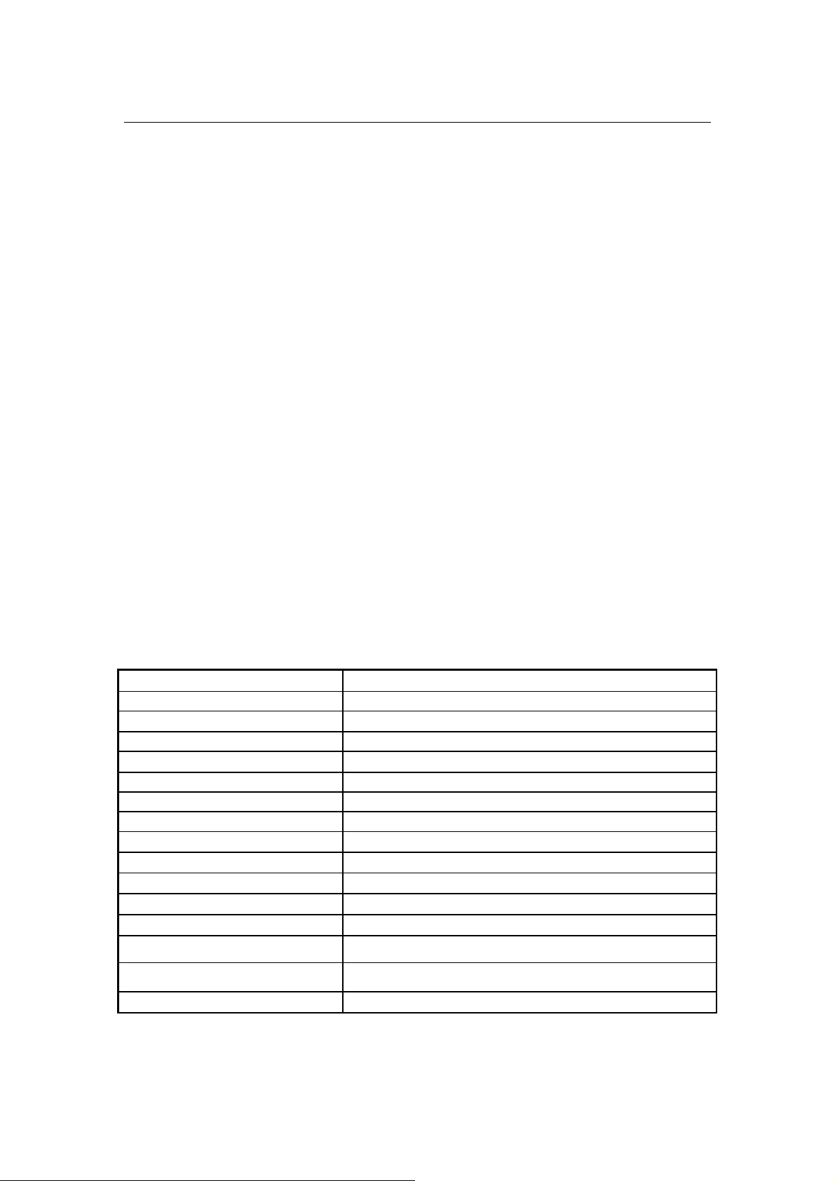
Model No. SSD3840-V2
LCD Display 38" Resizing LCD, Local Dimming Display
Display Area (mm) 930.2 (H) x 243.2 (V)
Display Surface Anti-Glare hard coated
Luminance 2000 cd/m2
Resolution 1920 x 502
Contrast Ratio 5600 : 1 (Typ)
Display Colors 16.7M colors
Pixel Arrangement RGB (Red, Green, Blue) vertical stripe
Pixel Pitch (mm) 0.4845 x 0.4845 mm
Response Time 6.5ms (Typ.)
Signal Connector 15 Pin D-sub, 29 Pin DVI
F/R Control Button Power Switch, Menu, Select (+,-)
OSD Menu
Power Consumption
Brightness, Contrast, H/V Position, Color, Phase, Clock, Language,
Management
Black(100%)=>23W,White(100%)=>130W
Black(50%)&White(50%)=>75W
Option Touch for customize (Resistive/ Capacitive)
※ Specifications subject to change without notice.
SSD= Panel+ LED Driving Board + Control Board
Page 4
Page 5
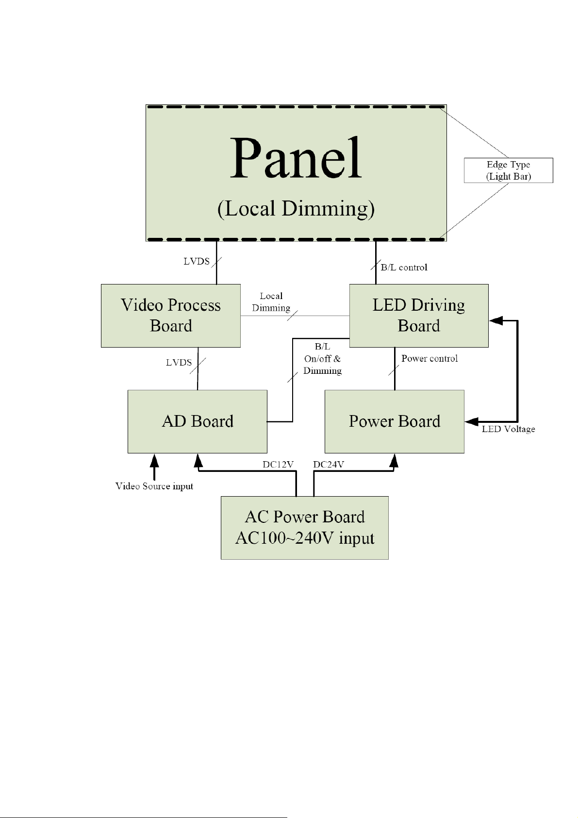
LOCAL DIMMING BLOCK DIAGRAM
Page 5
Page 6
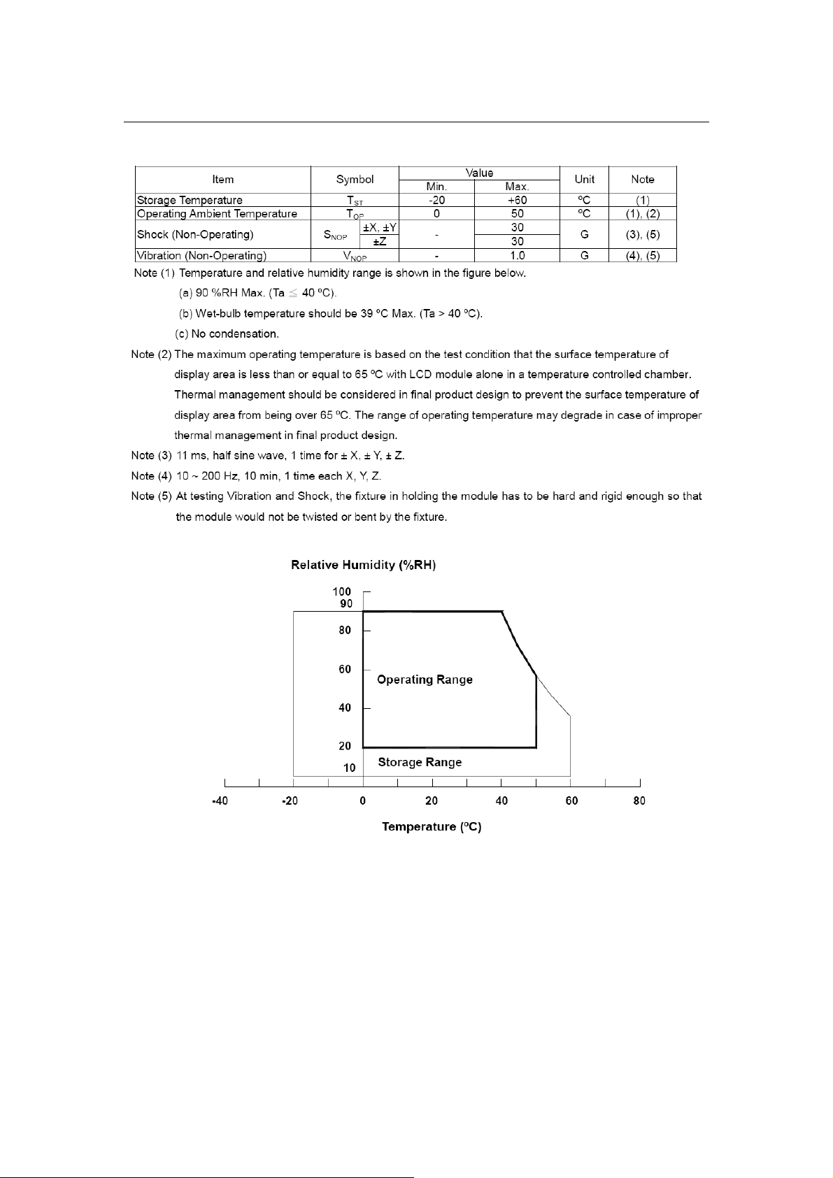
2.0 ABSOLUTE MAXIMUM RATINGS
ABSOLUTE RATINGS OF ENVIRONMENT
Page 6
Page 7
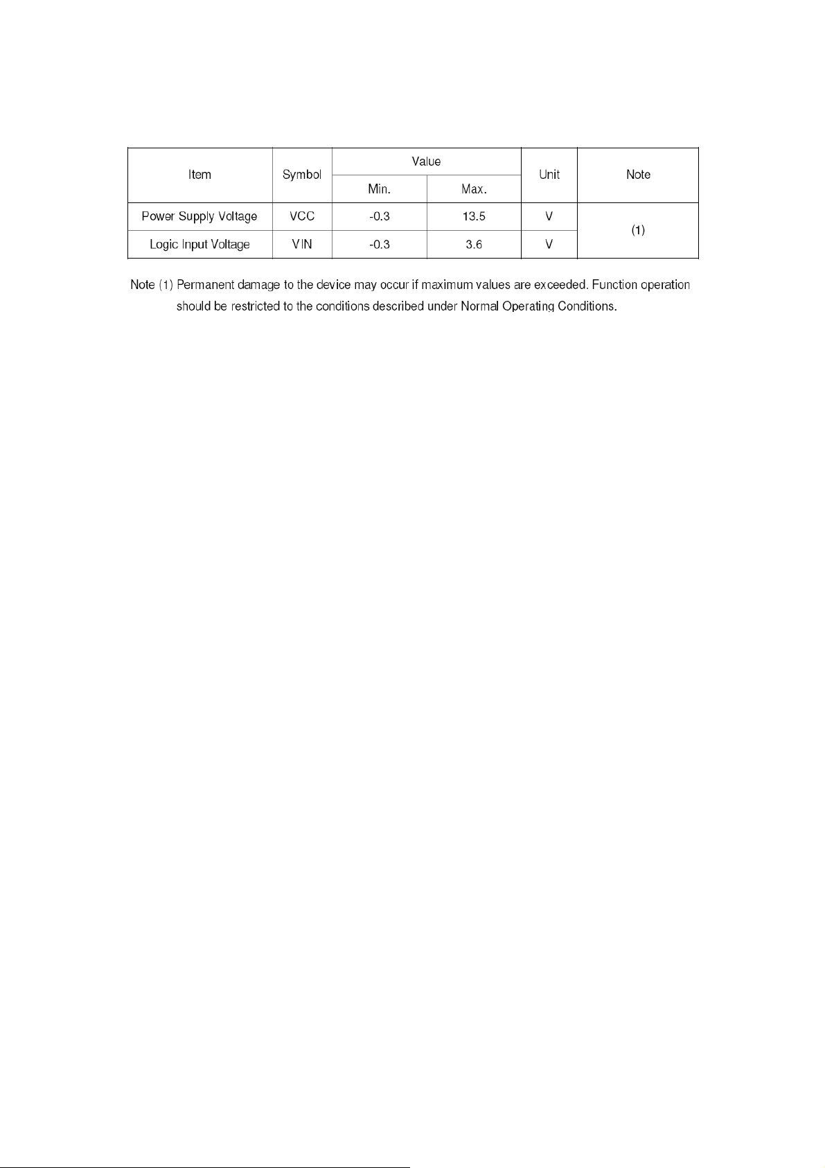
ELECTRICAL ABSOLUTE RATINGS
Page 7
Page 8
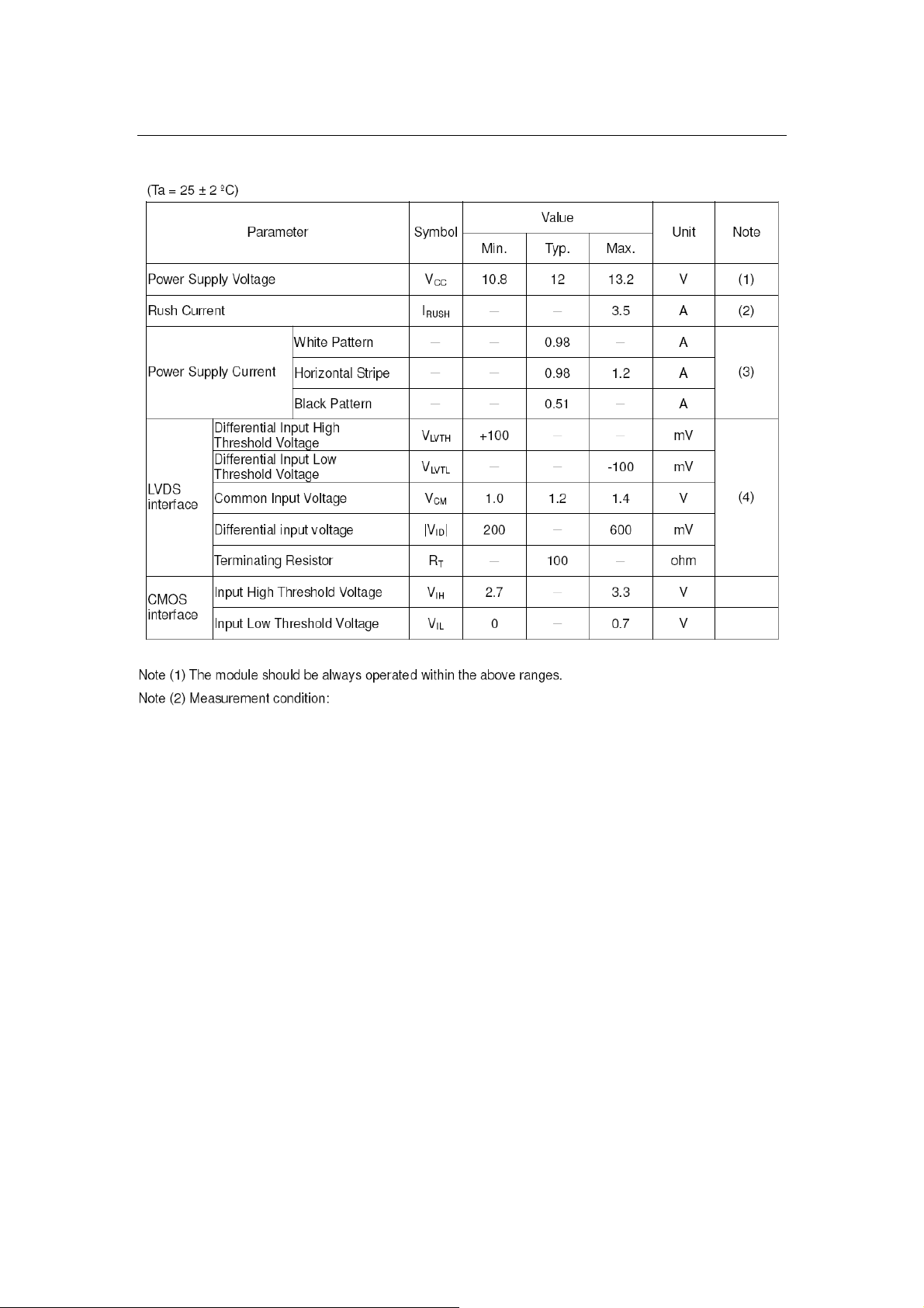
3.0 ELECTRICAL CHARACTERISTICS
TFT LCD MODULE
Page 8
Page 9
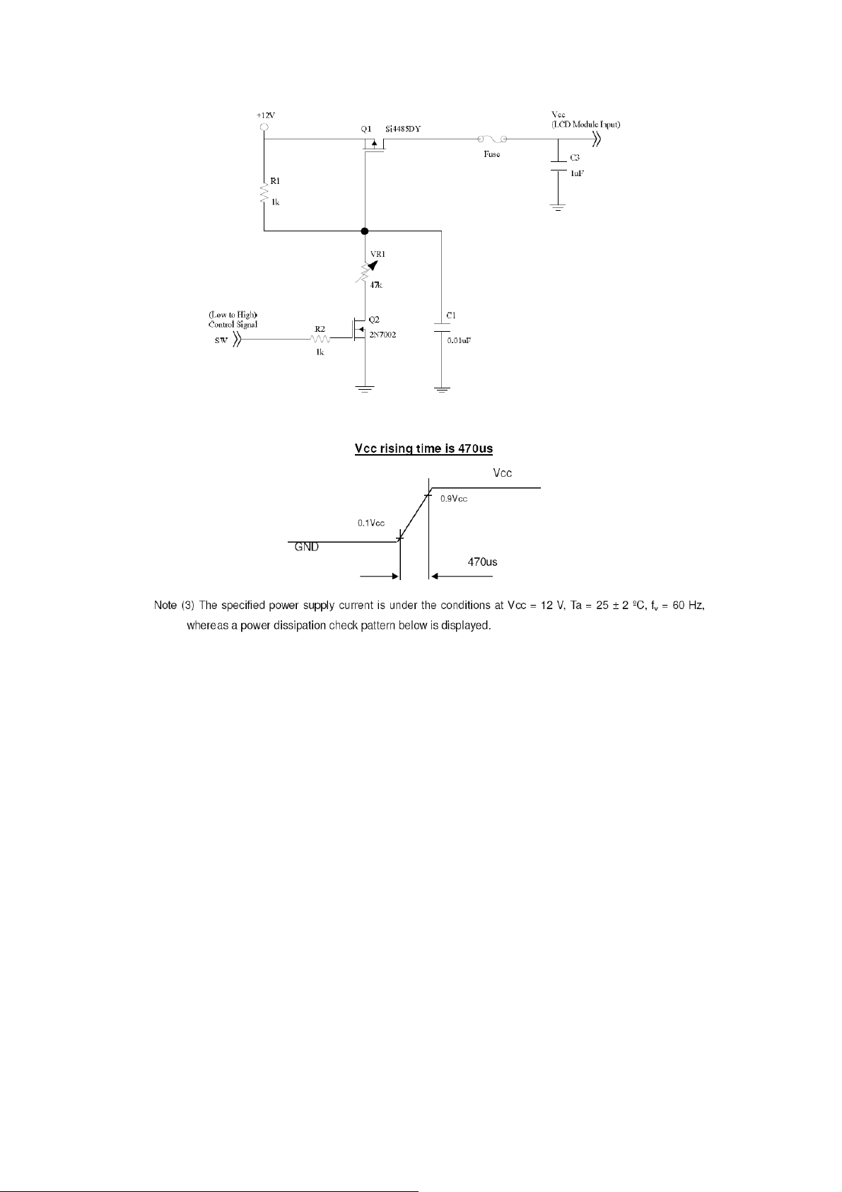
Page 9
Page 10
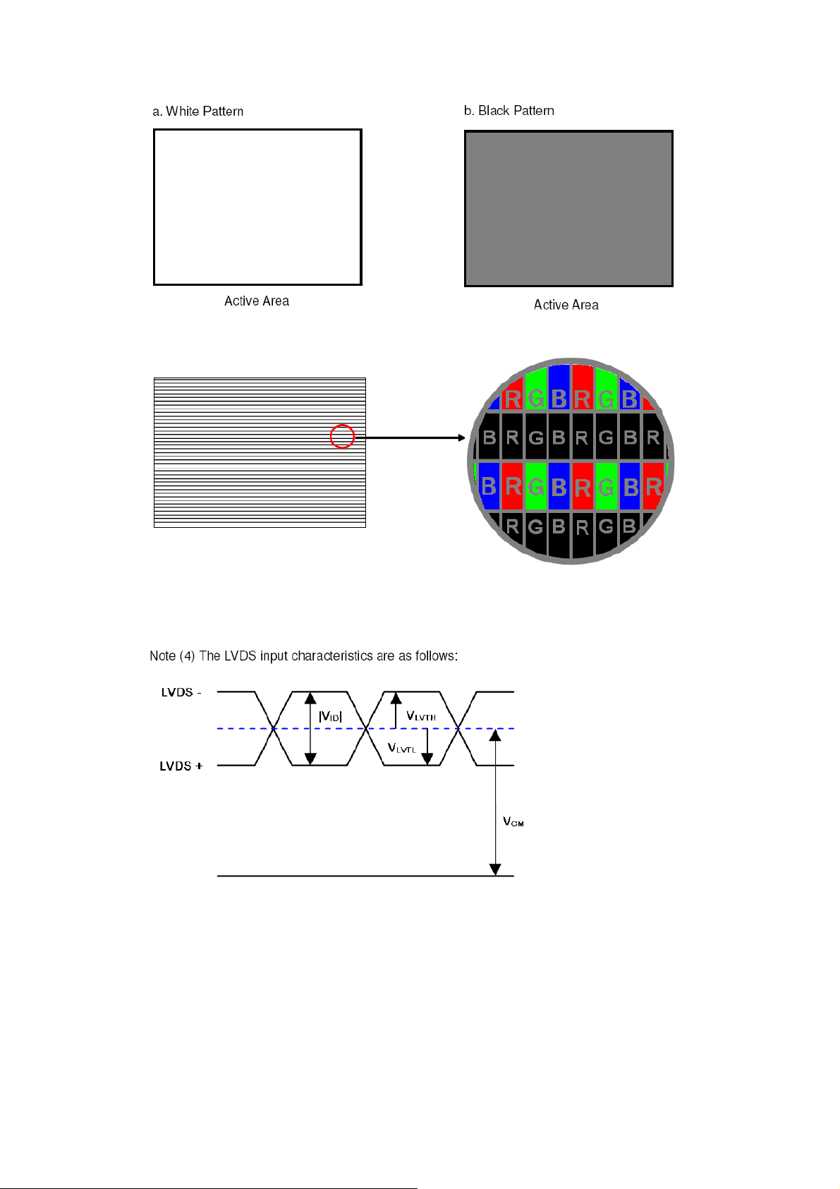
Page 10
Page 11
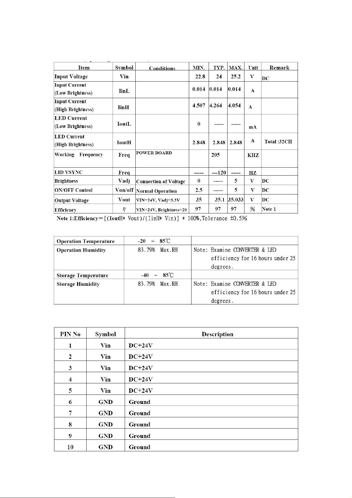
LED Driving Board
Operating Characteristics
Environment
POWER BOARD
CON1: JST S10B-PH-SM3-TB or Compatible
Page 11
Page 12

J1: JST S8B-PH-SM3-TB or Compatible
J2: JST S8B-PH-SM3-TB or Compatible
Page 12
Page 13
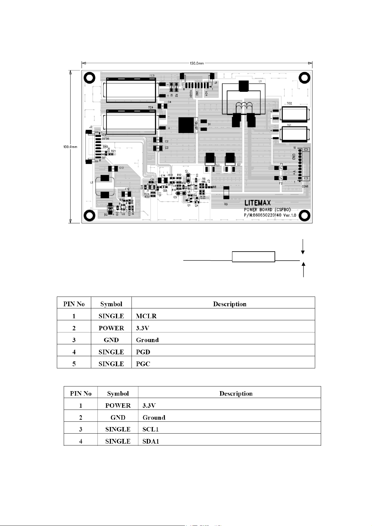
Mechanical Characteristics
Dimension: 150mm*100mm*16mm
16mm
MAIN BOARD
J1 RECORD MCU: 1.25mm,5P
J2 I2C:1.25mm
Page 13
Page 14
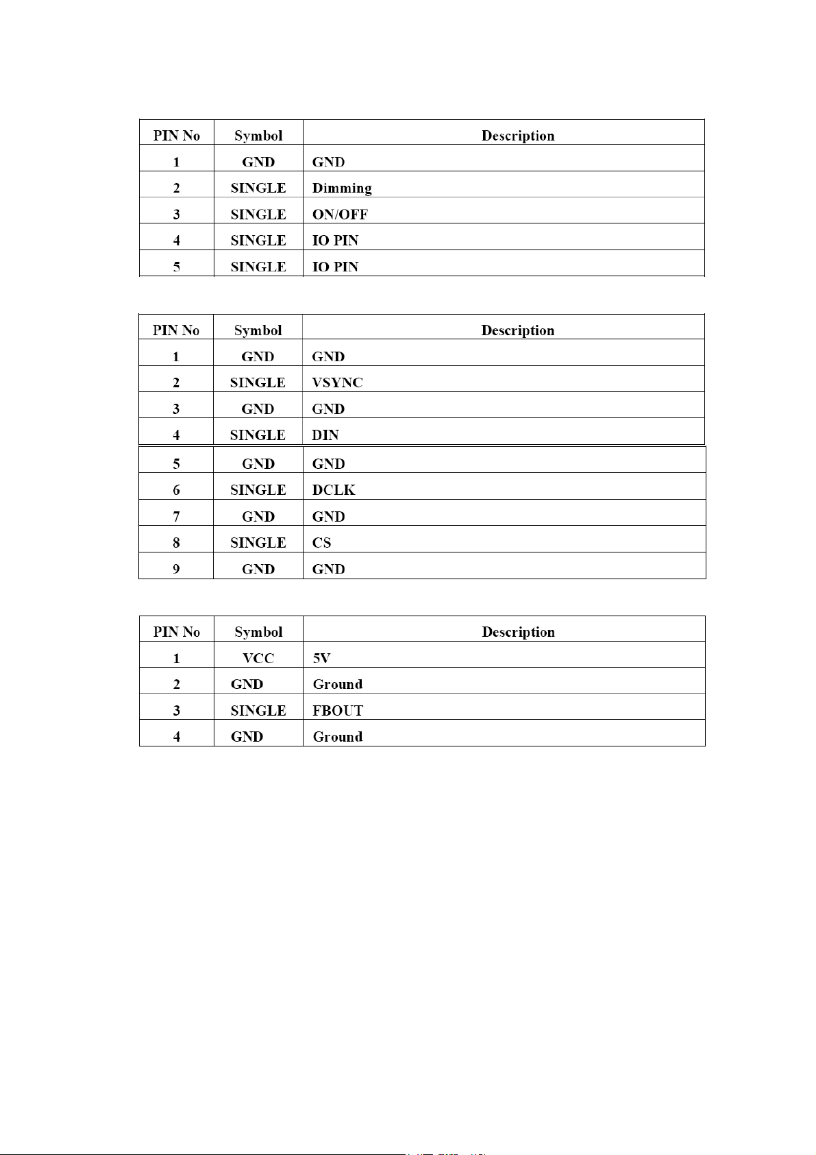
J3 TO AD BOARD:2.0mm
J4 SPI INTERFACE: 1.25mm
J5 2.0mm 4p
Page 14
Page 15
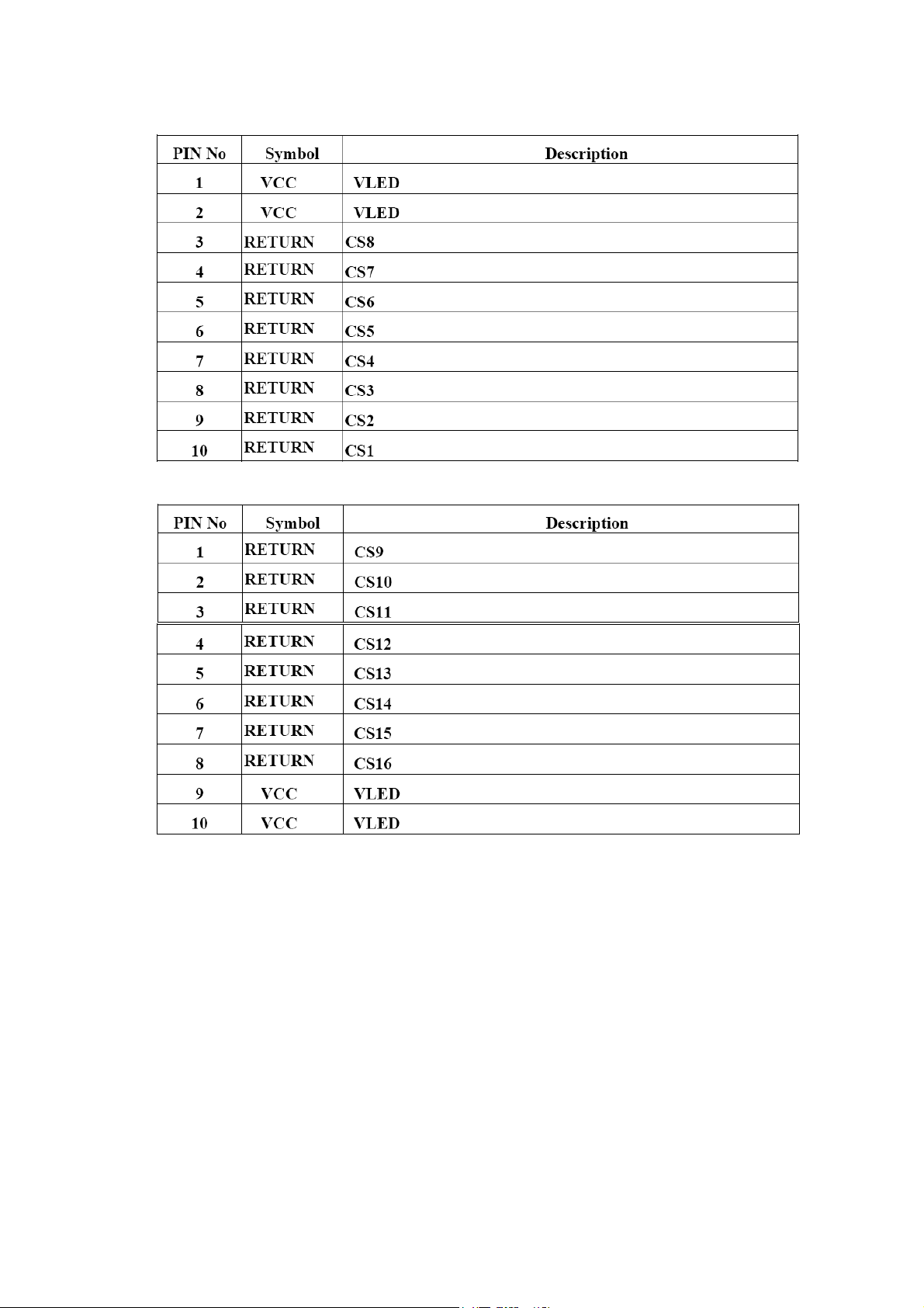
J6 TO BACKLIGHT:1.0mm
J7 TO BACKLIGHT:1.0mm
Page 15
Page 16
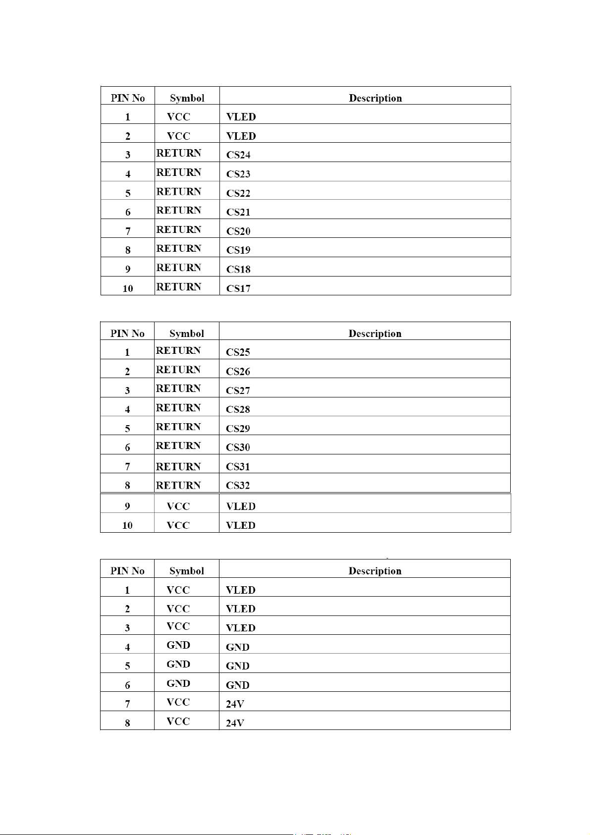
J8 TO BACKLIGHT:1.0mm
J9 TO BACKLIGHT:1.0mm
J10 TO POWER BOARD:JST S8B-PH-SM3-TB or Compatible
Page 16
Page 17
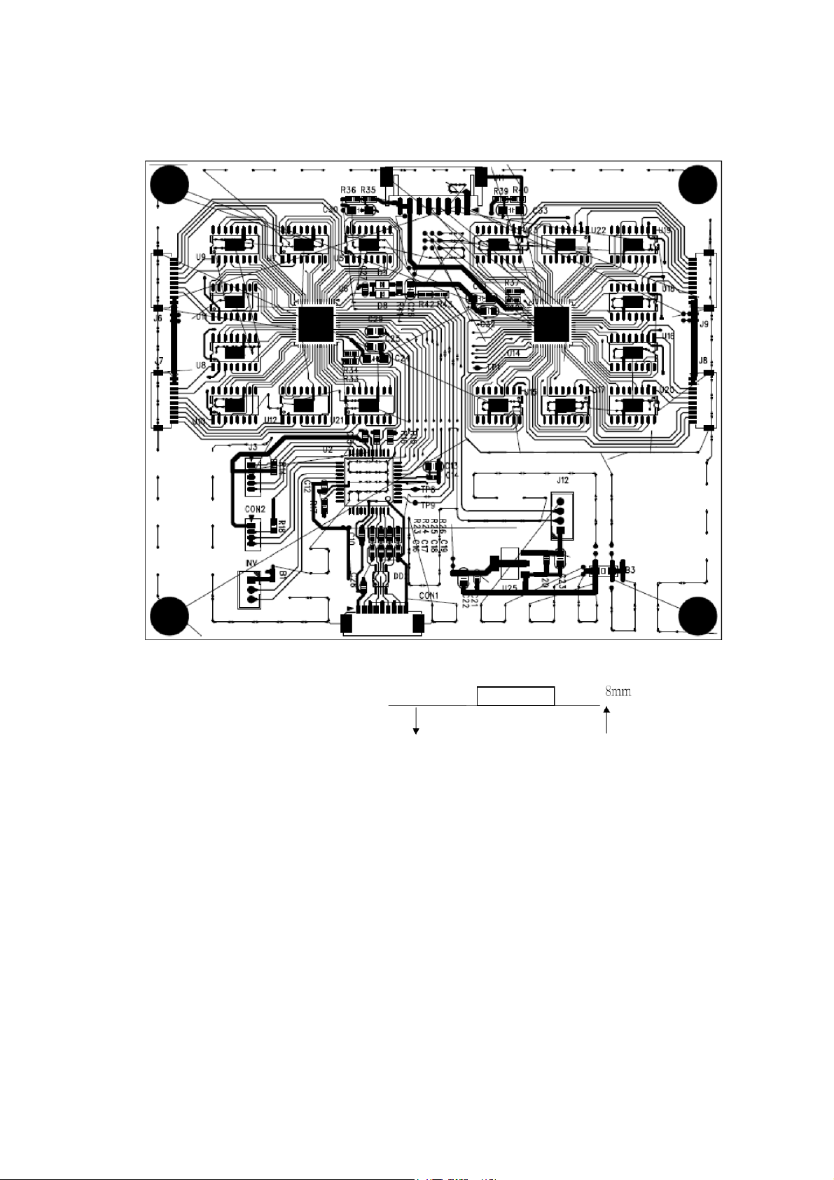
Mechanical Characteristics
Dimension: 120mm*100mm*8mm
Page 17
Page 18
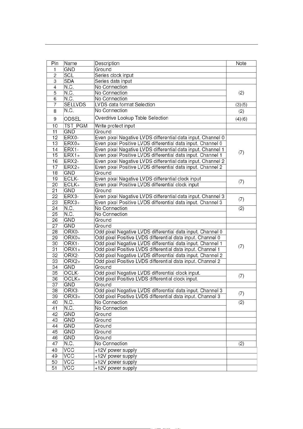
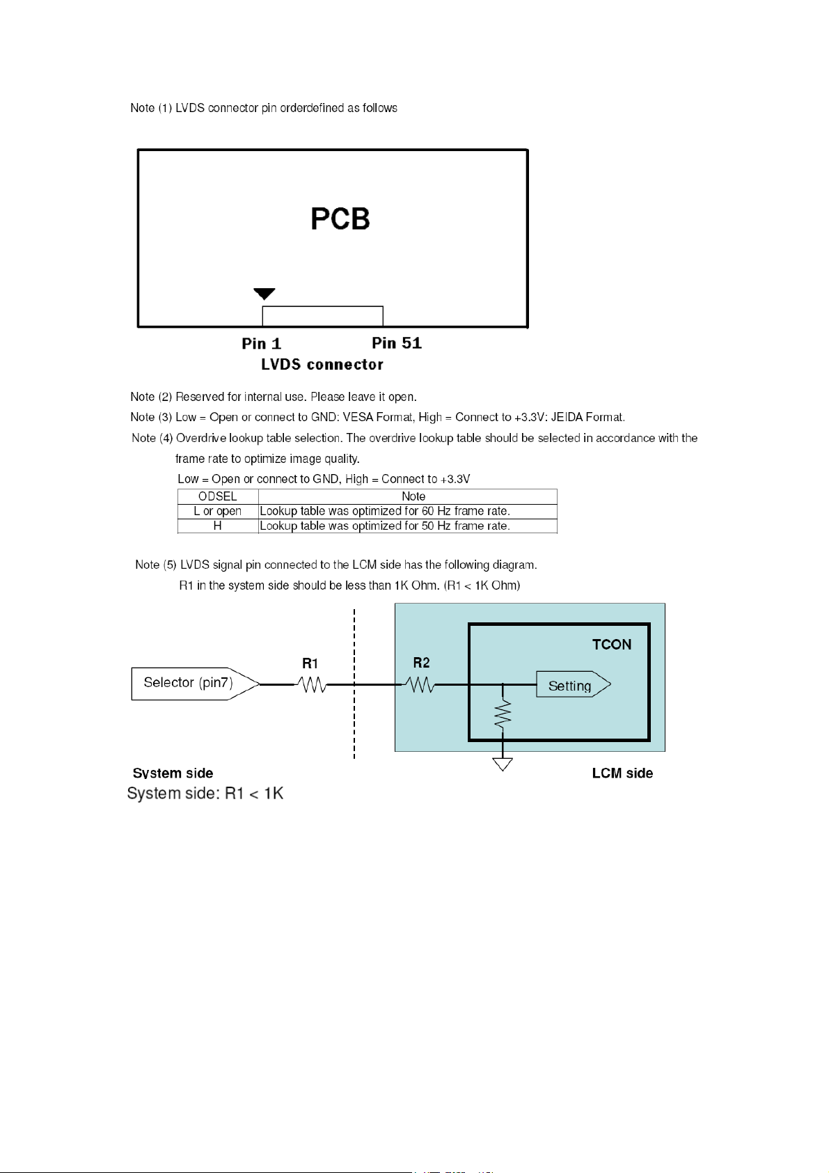
4.0 INPUT TERMINAL PIN ASSIGNMENT
TFT LCD MODULE
Page 18
Page 19
Page 19
Page 20
Page 20
Page 21
Page 21
Page 22
Page 22
Page 23
Page 23
Page 24
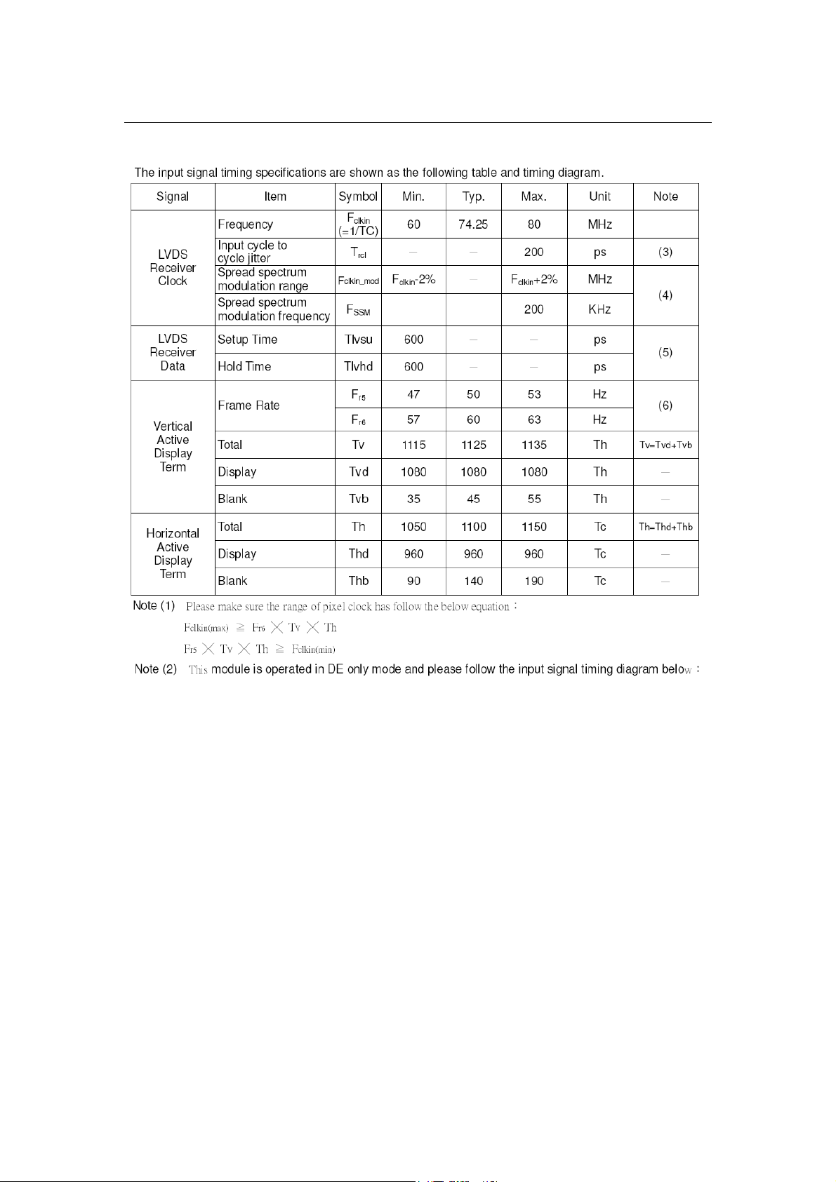
5.0 INTERFACE TIMING
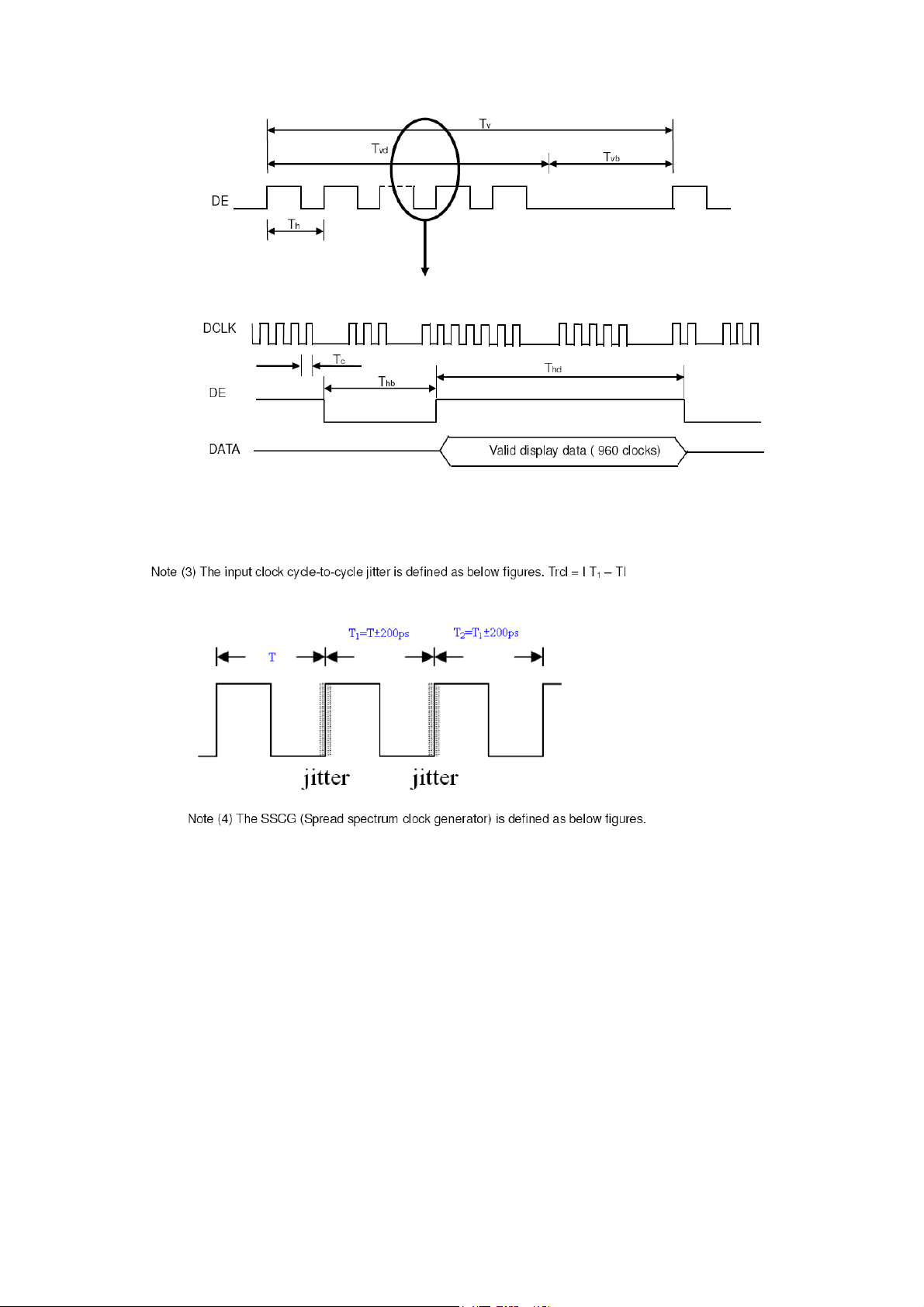
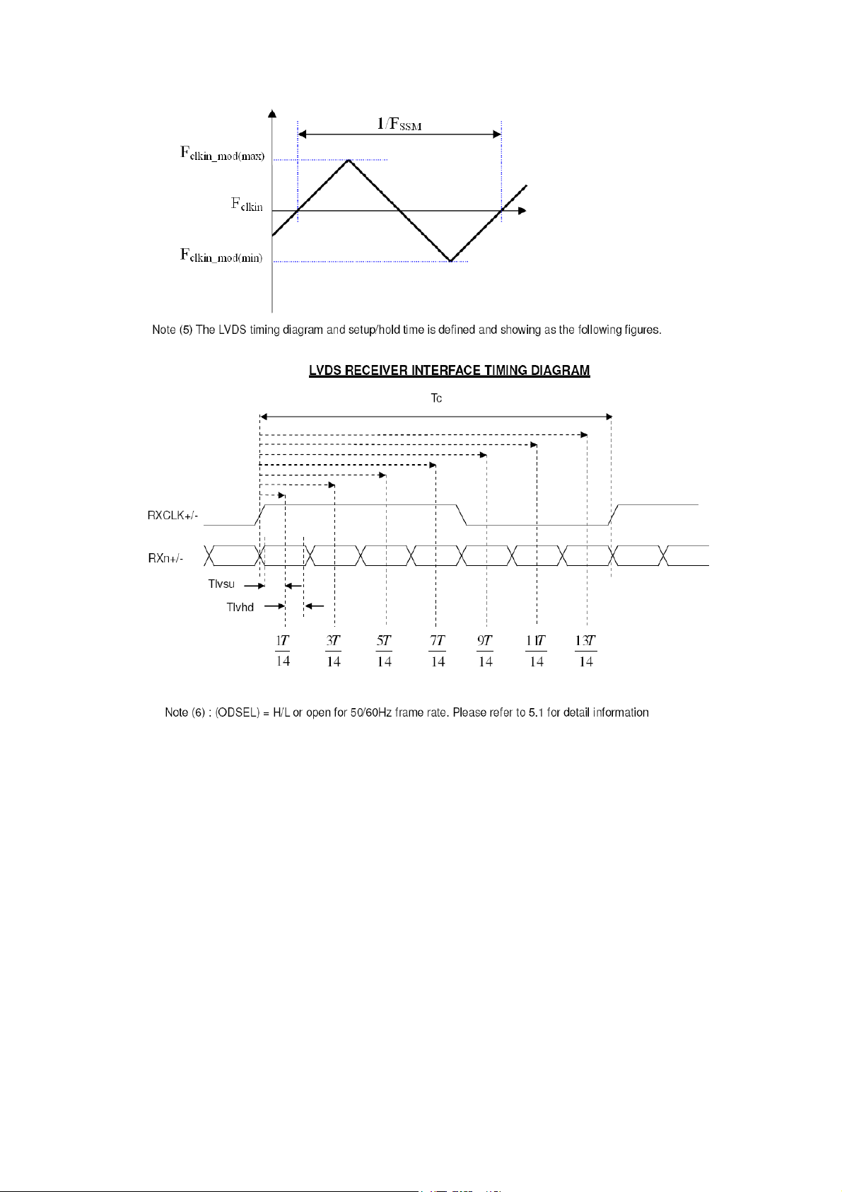
INPUT SIGNAL TIMING SPECIFICATIONS (Ta = 25 ± 2 ºC)
Page 24
Page 25
Page 25
Page 26
Page 26
Page 27
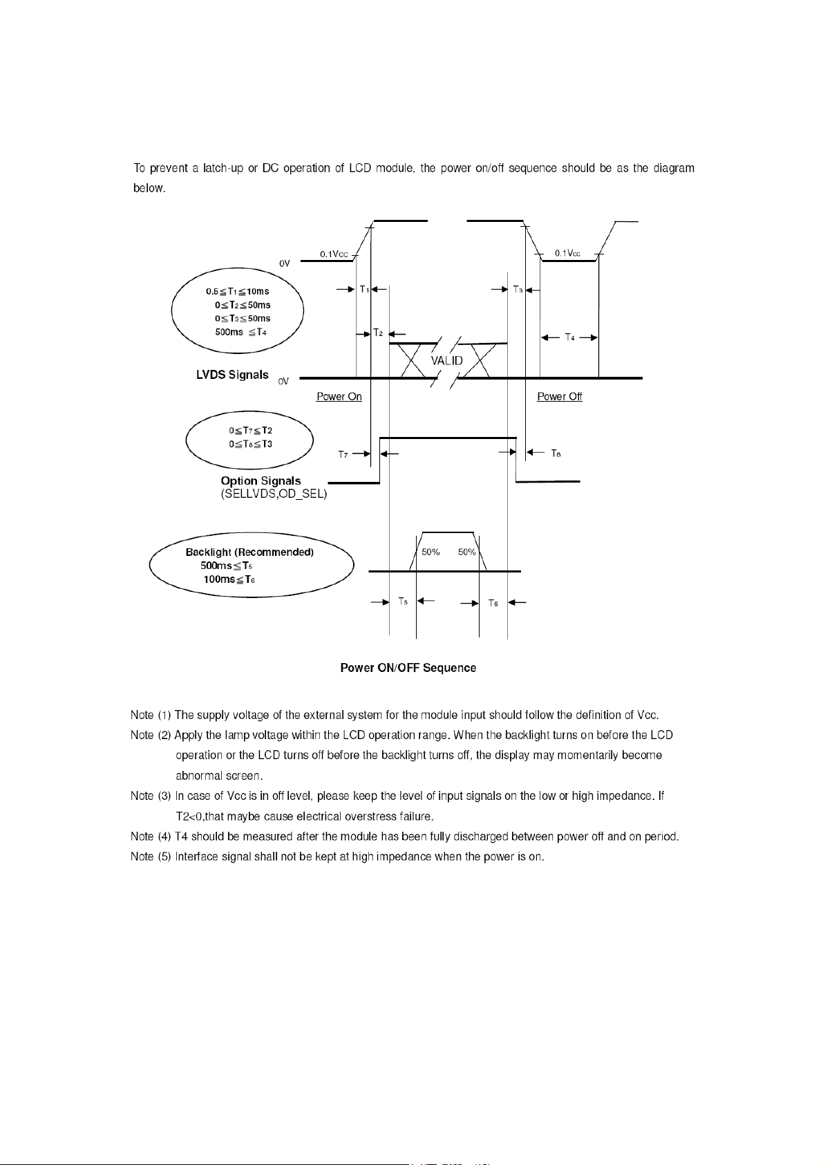
POWER ON/OFF SEQUENCE
(Ta = 25 ± 2 ºC)
Page 27
Page 28
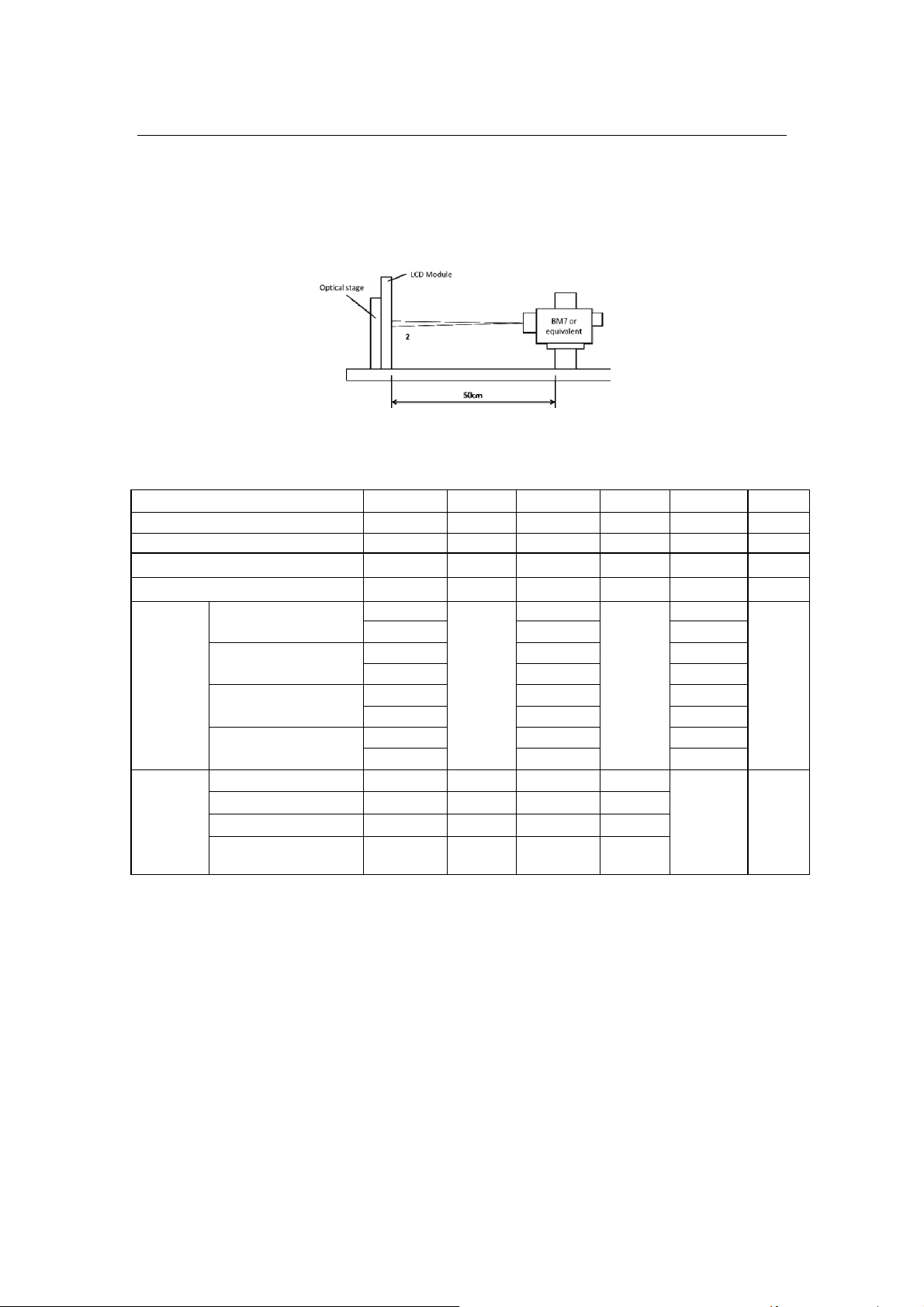
6.0 OPTICAL CHARACTERISTICS
TEST CONDITIONS
Optical characteristics are determined after the unit has been ‘ON’ and stable for approximately 45
minutes in a dark environment at 25. The values specified are at an approximate distance 50cm ℃ from
the LCD surface at a viewing angle of Φ and θ equal to 0°.
FIG. 1 Measurement Set Up
Optical Specifications
Item Symbol Min. Typ. Max. Unit Note
Contrast Ratio CRn - 5600 - - [1]
Luminance of White LAVE 1800 2000 - cd/m2 [2]
Uniform Lu - 80 - %
Response Time τDRV - 6.5 - ms [3]
Chroma
ticity
Viewing
Angle
Red
Green
Blue
White
x axis, right(φ=0°) θ
Rx
Ry 0.330 Gx 0.316 Gy 0.634 Bx 0.147 -
Typ.-0.
03
By 0.047 Wx 0.314 Wy 0.348 -
r - 88 -
x axis, left(φ=180°) θl - 88 -
y axis, up(φ=90°) θu - 88 -
y axis, down
(φ=0°)
d - 88 -
θ
0.640
Typ.+0
.03
-
[4]
Degree -
Note:
1. Contrast Ratio(CR) is defined mathematically as :Surface Luminance at all white pixels CR
= Surface Luminance at all black pixels. It is measured at center 1-point.
2. Surface luminance are determined after the unit has been ‘ON’ and 1Hourafterlighting the
backlight in a dark environment at 25±2°C. Surface luminance is the luminance value at
center 1-point across the LCD surface 50cm from the surface with all pixels displaying white.
For more information see the FIG. 2.
3. The output signals of photo detector are measured when the input signals are changed for
“White” to “Black” (falling time) and form “Black” to “White” (rising time), respectively. The
response time Interval is between 10% and 90% of amplitudes, see the FIG.3.
4. Viewing angle is the angle at which the contrast ratio is greater than 10. The angles are
determined or the horizontal or x axis and the vertical or y axis with respect to the z axis
which is normal to the LCD module surface. For more information, seethe FIG. 4.
Page 28
Page 29
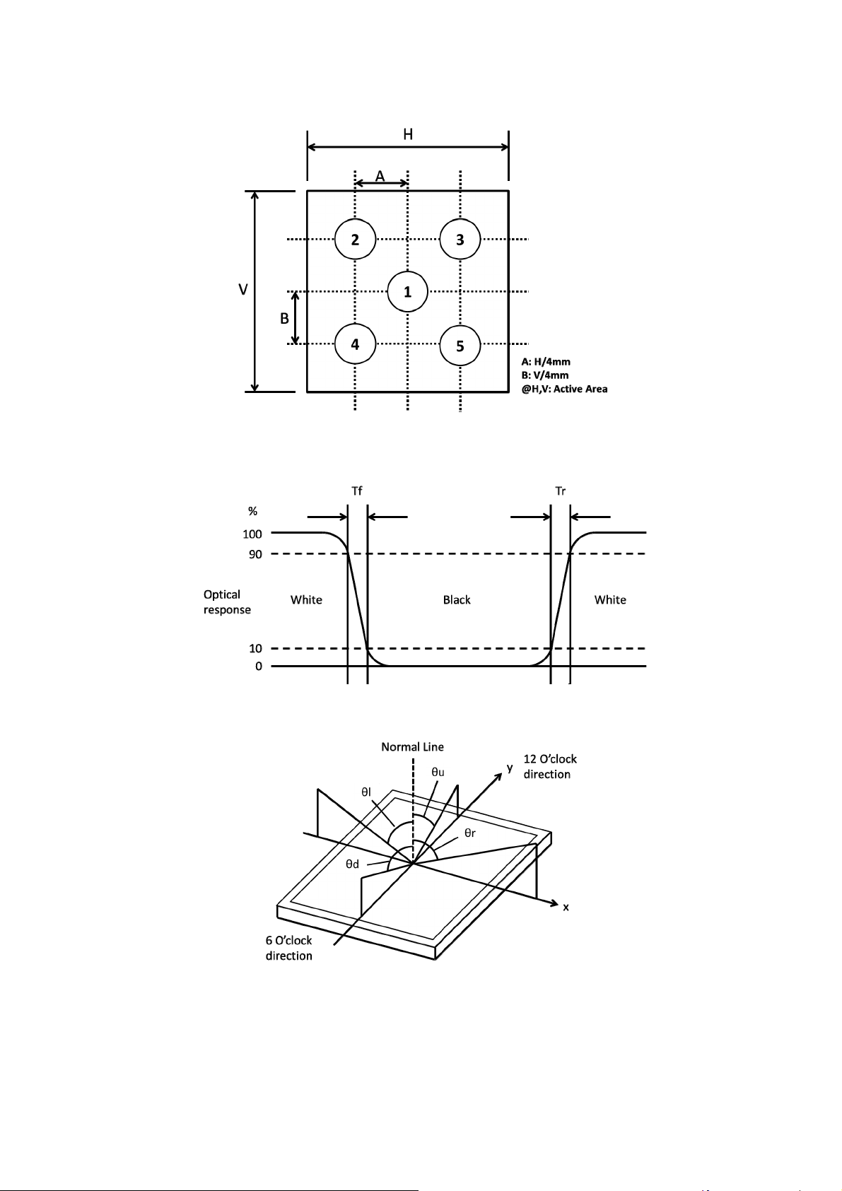
Measuring point for surface luminance & measuring point for luminance variation.
FIG. 2 5 Points for Luminance Measure
Response time is defined as the following figure and shall be measured by switching the input
signal for “White” and “Black”.
FIG. 3 Response Time
Definition for viewing angle
FIG. 4 Viewing Angle
Page 29
Page 30
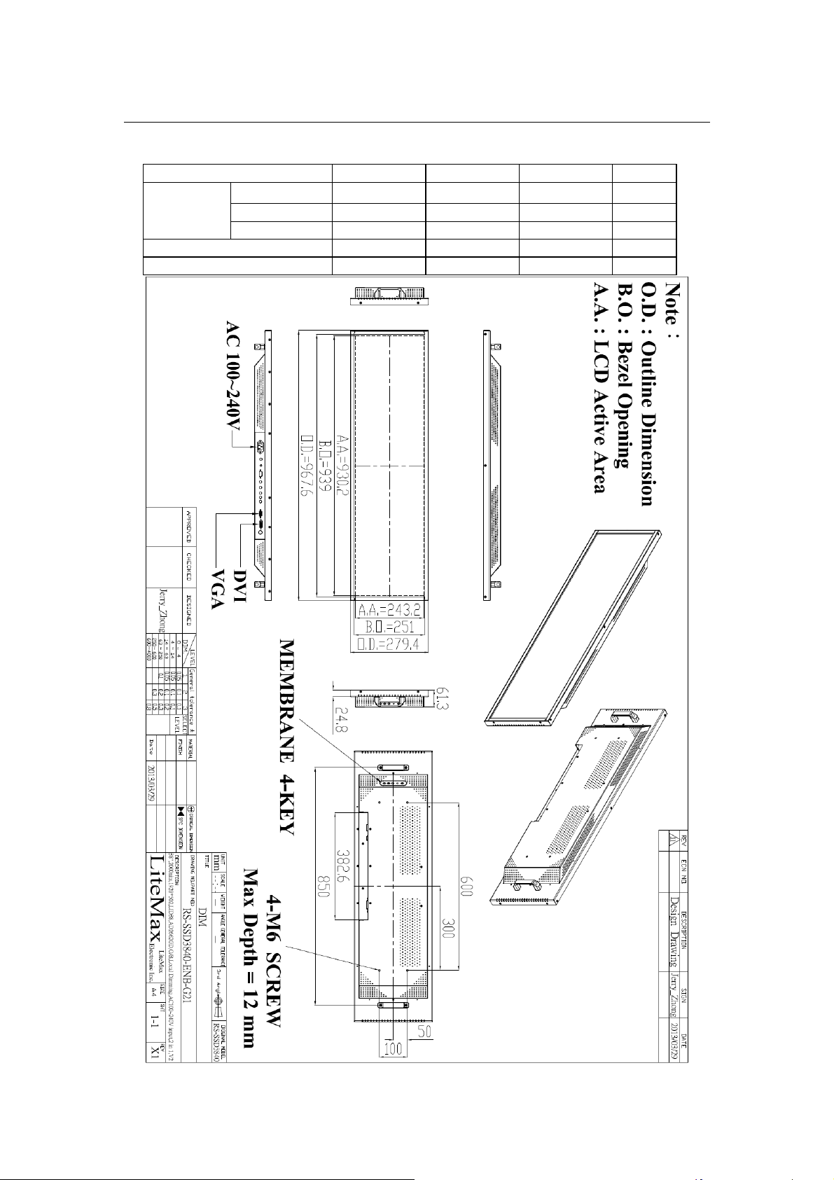
7.0 MECHANICAL CHARACTERISTICS
SSD3840-V2 MECHANICAL SPECIFICATION
Item Min. Typ. Max. Unit
Module
Size
Weight (Module only) - 10.5 - kg
Weight (1 module per box) - 21 - kg
Horizontal(H) - 967.6 - mm
Vertical(V) - 279.4 - mm
Depth(D) - 61.3 - mm
Page 30
Page 31
8.0 PRECAUTIONS
HANDLING PRECAUTIONS
(1) The module should be assembled into the system firmly by using every mounting hole.
Be careful not to twist or bend the module.
(2) While assembling or installing modules, it can only be in the clean area. The dust and oil
may cause electrical short or damage the polarizer.
(3) Use fingerstalls or soft gloves in order to keep display clean during the incoming
inspection and assembly process.
(4) Do not press or scratch the surface harder than a HB pencil lead on the panel
because the polarizer is very soft and easily scratched.
(5) If the surface of the polarizer is dirty, please clean it by some absorbent cotton or soft
cloth. Do not use Ketone type materials (ex. Acetone), Ethyl alcohol, Toluene, Ethyl acid
or Methyl chloride. It might permanently damage the polarizer due to chemical reaction.
(6) Wipe off water droplets or oil immediately. Staining and discoloration may occur if
they left on panel for a long time.
(7) If the liquid crystal material leaks from the panel, it should be kept away from the eyes or
mouth. In case of contacting with hands, legs or clothes, it must be washed away
thoroughly with soap.
(8) Protect the module from static electricity, it may cause damage to the C-MOS Gate Array
IC.
(9) Do not disassemble the module.
(10) Do not pull or fold the lamp wire.
(11) Pins of I/F connector should not be touched directly with bare hands.
STORAGE PRECAUTIONS
(1) High temperature or humidity may reduce the performance of module. Please store
LCD module within the specified storage conditions.
(2) It is dangerous that moisture come into or contacted the LCD module, because the
moisture may damage LCD module when it is operating.
(3) It may reduce the display quality if the ambient temperature is lower than 10 ºC. For
example, the response time will become slowly, and the starting voltage of lamp will be
higher than the room temperature.
OPERATION PRECAUTIONS
(1) Do not pull the I/F connector in or out while the module is operating.
(2) Always follow the correct power on/off sequence when LCD module is connecting and
operating. This can prevent the CMOS LSI chips from damage during latch-up.
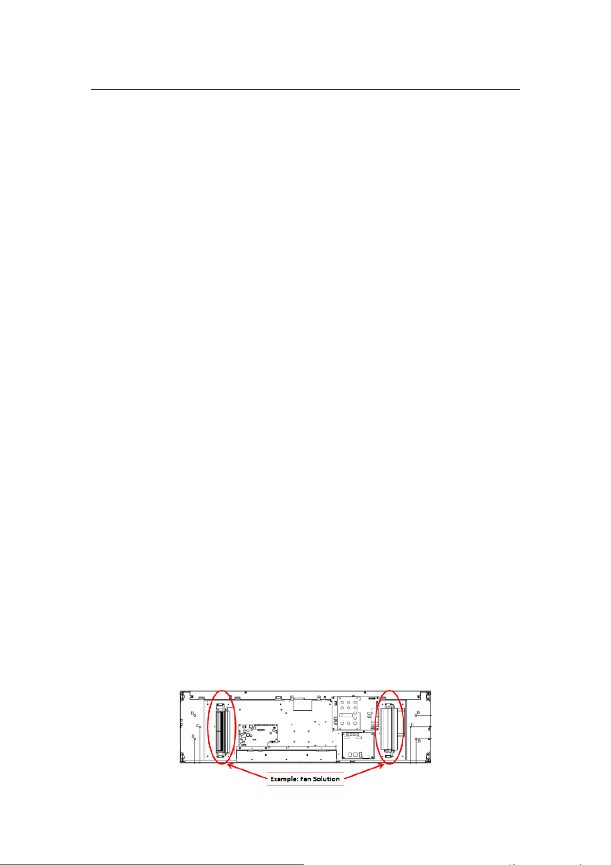
THERMAL PRECAUTIONS
(1) SSF/SSH3840 with 2000nits is LCD SKD without cooling system, and it’s easy to cause
overheating. If you ordered SSF/SSH3840, please devices good ventilation inside your
enclosure for fear of damaging by overheating.
Page 31
Page 32
9.0 AD2662GDVAR Board & OSD Functions
AD BOARD GENERAL SPECIFICATIONS
● Max Resolution Up To Full HD 1920x1080
● Analog RGB Input
● ULTRA-RELIABLE DVI INPUT
● CBVS, S-VIDEO, Ycbcr INPUT (optional)
● 1.5Wx2 Audio Out
● Dual/single LVDS interface
● Support Panel DC5V or 3.3V, 12V Output
● Automatic External Fan Control
● OSD Control
● Inverter 0~5V Dimming Control
● *External V.R. brightness control (optional)
● *External light sensor brightness control (optional)
● *External RS232 control (optional)
● Input Power 12Vdc
SUPPORTED TIMING (*by your panel resolution)
The following table displays optimum quality modes that the LCD monitor provides. If the other
video modes are used, the monitor will stop working or display a poor quality picture.
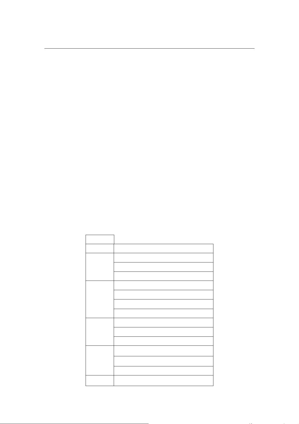
TIMMING
MODE RESOLUTION
VGA 640x480@60Hz
SVGA 800x600@56Hz
XGA 1024x768@60Hz
640x480@72Hz
640x480@75Hz
800x600@60Hz
800x600@72Hz
800x600@75Hz
1024x768@70Hz
1024x768@75Hz
SXGA 1280x1024@60Hz
1280x1024@70Hz
1280x1024@75Hz
WXGA 1366x768@60Hz
Page 32
Page 33

WSXGA+ 1680x1050@60Hz
SXGA+ 1400x1050@60Hz(Pixel f 101.000MHz)
1400x1050@60Hz(Pixel f 121.750MHz)
1400x1050@75Hz
UXGA 1600X1200@60Hz
1600x1200@65Hz
1600x1200@75Hz
FHD 1920X1080@60Hz
1920X1080@65Hz
1920X1080@75Hz
Page 33
Page 34
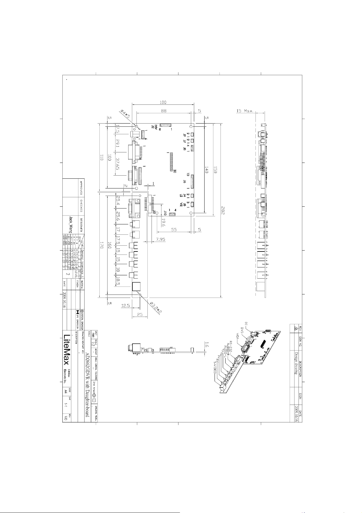
AD BOARD OUTLINE DIMENSION
unit: mm
Page 34
Page 35

MEMBRANE CONTROL BUTTOM
POWER SWITCH: Pushing the power switch will turn the monitor on. Pushing it again to
turn the monitor off.
Power LED: Power ON-Green / Power off-No.
Up Key >: Increase item number or value of the selected item.
Menu Key: Enter to the OSD adjustment menu. It also used for go back to previous menu
for sub-menu, and the change data don’t save to memory.
Down Key <: Decrease item number or item value when OSD is on.
When OSD is off, it is hot key for input switch between VGA, AV,
and S-video.
Screen Adjustment Operation Procedure
1. Entering the screen adjustment
The setting switches are normally at stand-by. Push the Menu Key once to display the
main menu of the screen adjustment. The adjustable items will be displayed in the main
menu.
2. Entering the settings
Use the Down Key < and Up Key > buttons to select the desired setting icon and push
the SELECT button to enter sub-menu.
3. Change the settings
After the sub-menu appears, use the Down Key < and Up Key > buttons to change the
setting values.
4. Save
After finishing the adjustment, push the SELECT button to memorize the setting.
5. Return & Exit the main menu
Exit the screen adjustment; push the “MENU” button. When no operation is done
around 30 sec (default OSD timeout), it goes back to the stand-by mode and no more
switching is accepted except MENU to restart the setting.
Page 35
Page 36
OSD FUNCTIONS
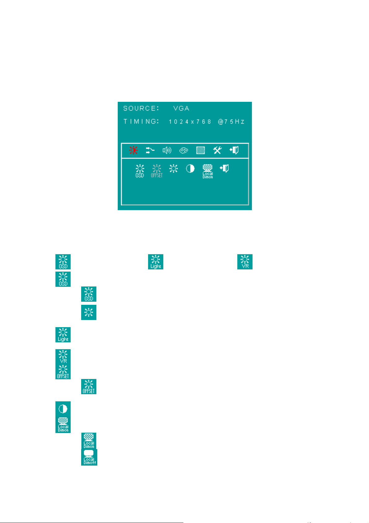
Here are some instructions for you to use the OSD (On Screen Display). By pressing the
“menu”, you will see the below picture.
Timing shows resolution, H-frequency,and V-frequency of the panel.Version shows the
firmware control version. This 2 information is not changeable by user.
There are 7 sub pages inside the OSD manual, Brightness, Signal select, Sound, Color,
Image, Tools, and Exit.
When you press “menu” button, you enter the “Brightness” sub page. You will see 5
selections:
press ’’menu’’ press ’’menu press ’’menu’’
OSD Brightness:
press ’’right’’ key
press “menu” once, you can go into adjust the brightness. Press “left”
you can dim down the brightness to “0”, while press “right” you can
increase the brightness to “100”.
Ambient light sensor: press this Icon, must to accompany with Litemax
ambient light sensor to auto dimming.(OPTION)
Potentiometer: press this icon, adjust VR function.(OPTION)
Ambient light sensor with OSD offset: press this Icon
Press ’menu’’ once, you can adjust min. luminance to fit your
application (OPTION)
Contrast: Press “menu” and “right” you can adjust the contrast from “0” to “100” by
pressing the “left” and “right”.
LocalDimming function
LocalDimming On : default is LocalDimming On,this is to open
backlight become dynamic adjust.
LocalDimming Off : close LocalDimming function.
Page 36
Page 37
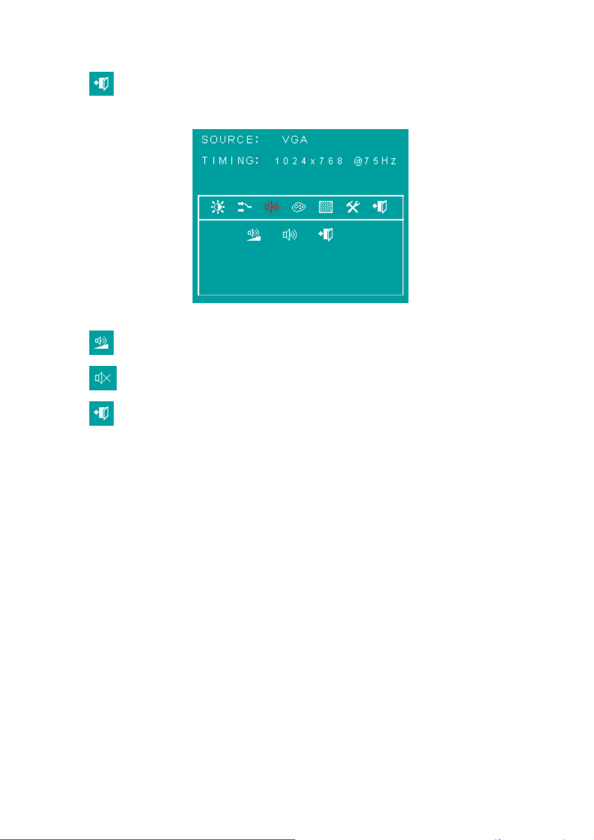
Exit: You can exit this sub menu back to normal screen.
Sound :
There are 3 options for “Sound” sub page.
Audio Volume: Audio volume adjustment.
Mute: You can mute the speakerby pressing this option.
Exit: back to the normal screen.
Page 37
Page 38
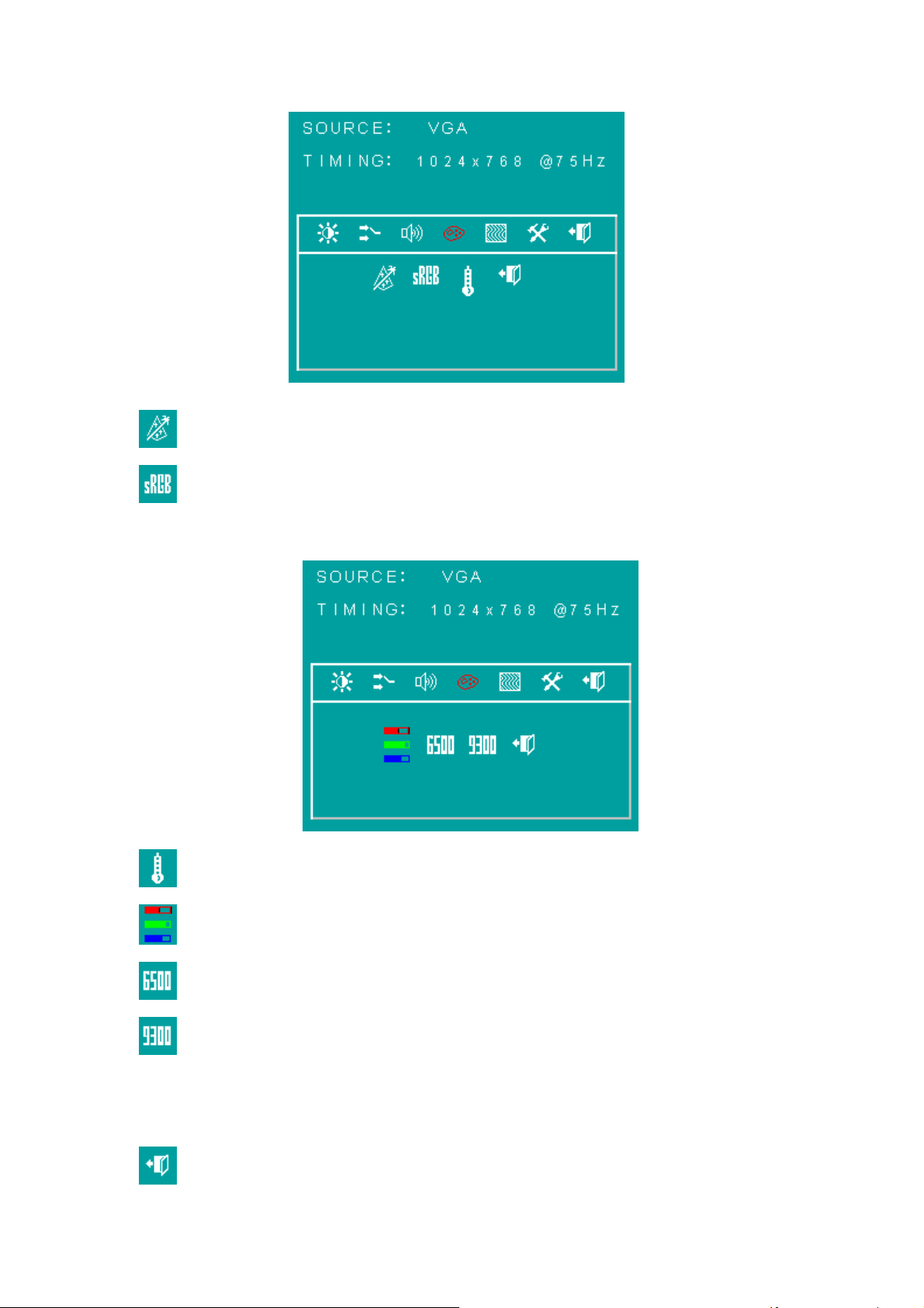
r
Auto Color: by press this “Auto Color” option, you can get the optimal color
performance.
SRGB: Windows standard color setting.
Color Tempture: You can have 3 options in this selection.
Color Tempture Use
Color Tempture_6500K
Color Tempture_93OOK
“user mode”, “6500K” (Warm color scheme), “9300K (Cold color scheme).
Def ault is “user”, and inside all “R”, “G”, and “B” are set “100”
Exit: back to the normal screen.
Page 38
Page 39
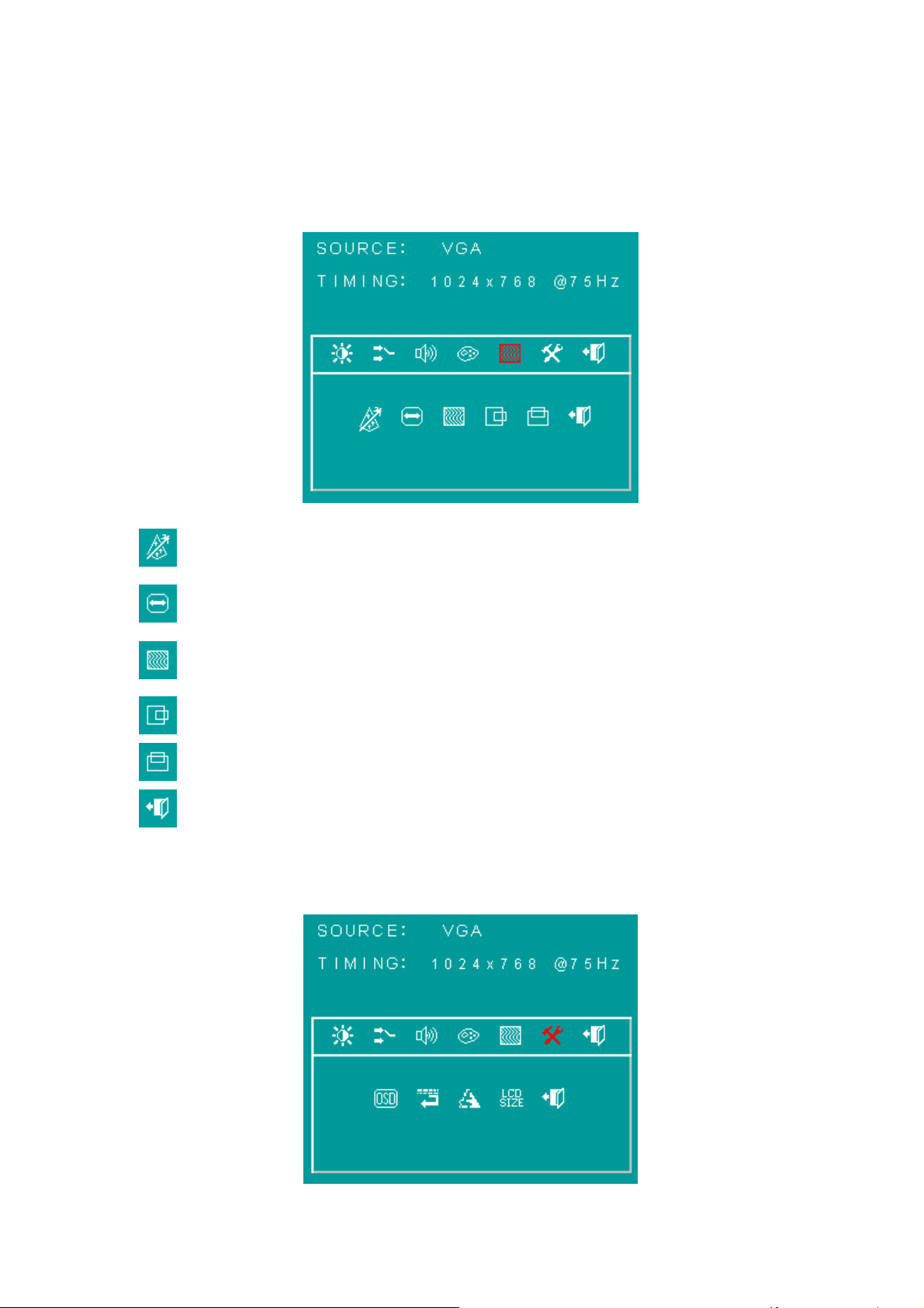
Image :
Go into the “Image” page, you can see below picture.
Auto just: Pressing this option, the AD5621 will adjust the optimal frequency of
horizontal and vertical. You will see “Auto tune….” On the screen for around
3 seconds.
Clock: If you are not satisfied about the Autotune result, you can adjust
manually by “Clock”.
The screen will be “wider” if you adjust this function.
Phase: If you see “double image” on characters, you can adjust “Phase” to
make it perfect image.
HPos: You can shift the screen horizontally by this function.
Vpos: You can shift the screen vertically by this function.
Exit: Back to normal screen.
TOOLS :
On the “Tools” sub menu, you will see 5 icons.
Page 39
Page 40
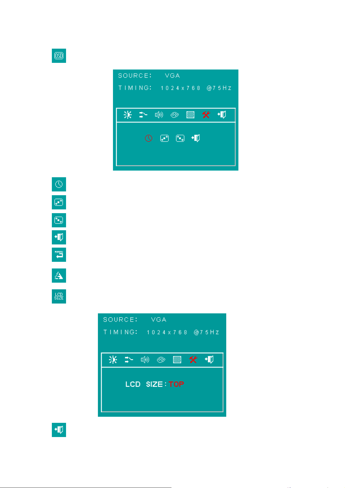
Osd Control: Select this option, you will see 4 more options:
D
Osd_time: You can selection the time of OSD from 2 sec. to 16 sec.
Osd_HPos: You can move the OSD horizontally over the screen.
Osd_VPos: You can move the OSD Vertically over the screen.
Exit: back to main menu.
Factory_Reset: By pressing this, the screen will be back to the factory setting
on very beginning and lost all the personal settings.
Sharpness: You can make the characters looks sharper.
LCD SIZE: Select this option, you can control LCD size 3 type,1.Bottom mode ,
2.Top mode,3.Compress mode.
Exit
Page 40
Page 41
BURNIN MODE :
Factory Burn-in mode: While your VGA cable is connected on the monitor, press “Menu”
and Left and Right <” simultaneously, you will see “BURN IN MODE” on the center of the
screen for 3 sec. Then unplug the VGA cable, the screen will show Red, Green, Blue,
White, and Black in sequence automatically.
You can plug in the VGA signal cable, and re-plug the power connector to exit the
burn-in mode.
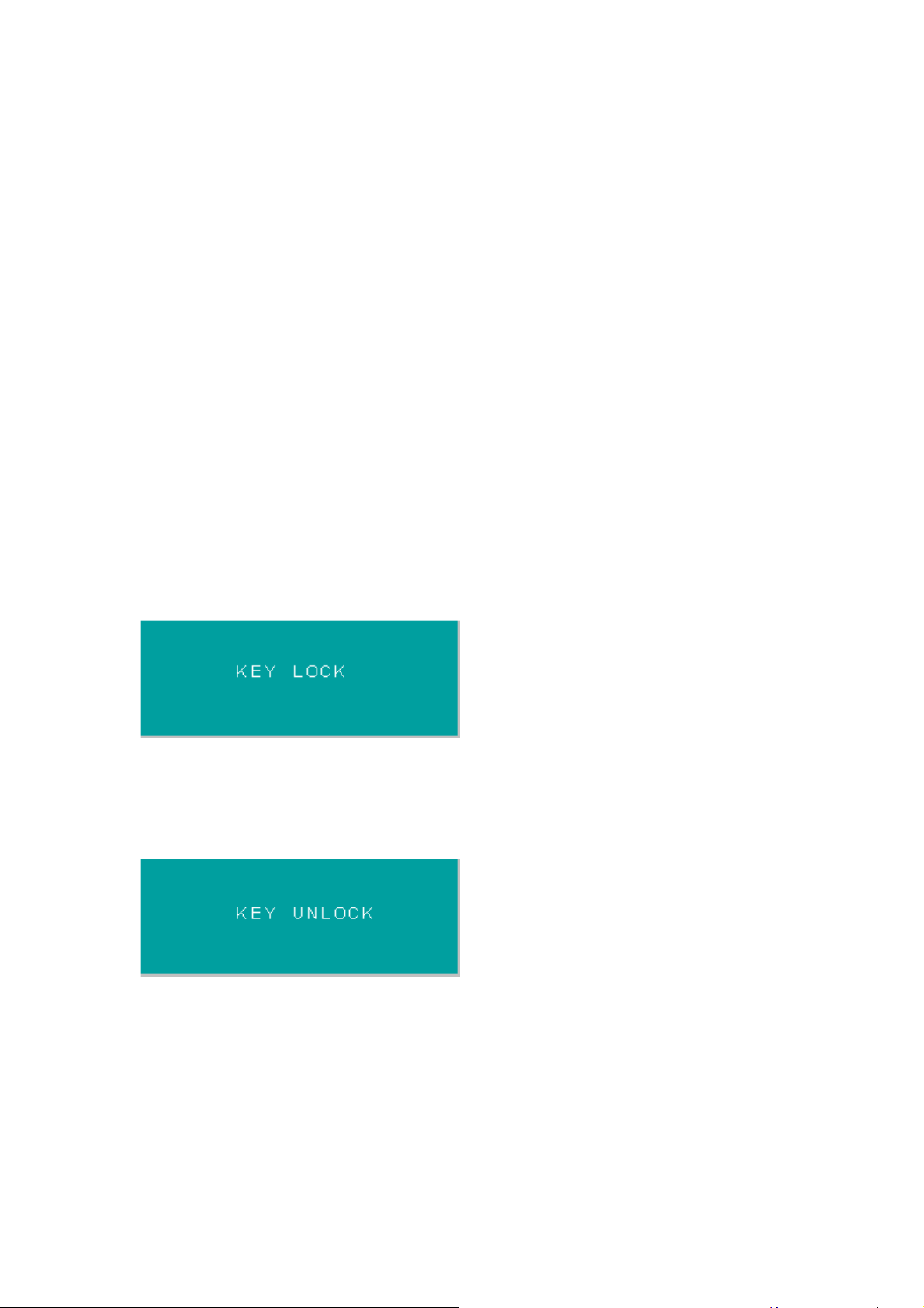
KEY LOCK MODE :
OSD Lock Function: It is possible to lock all the OSD buttons to prevent unauthorized
changes to occur by pressing “Menu” and “right >” buttons simultaneously. You will see
the “lock” icon below on the center of the screen for 3 seconds. If any button is pushed
after the lock function is initiated, the below icon will appear on the screen.'
To release the OSD lock, press “Menu” and “Right >”. The below icon will appear on the
center of the screen for 3 seconds. Now all OSD keys are active again.
Page 41
 Loading...