


Op er a tor's Guide Warnings
W
arnings
WARNING! THE RADIO CONTROLLED MODEL HELICOPTER BUILT FROM THIS KIT IS
NOT A TOY, AND IS NOT MEANT FOR CHILDREN. IT IS A FLYING MACHINE
CAPABLE OF CAUSING PROPERTY DAMAGE AND SERIOUS BODILY HARM
TO THE OPERATOR AND SPECTATORS IF NOT BUILT AND OPERATED
CORRECTLY AND RESPONSIBLY. ROTATING COMPONENTS, ESPECIALLY
THE MAIN ROTOR BLADES, ARE AN EVER-PRESENT DANGER.
WARNING! Helicopters, by their nature, are not positively stable. Even if assembled and
adjusted properly, helicopters will not hold a particular flight position without constant
control inputs from the pilot, and will not automatically recover from an unwanted
flight attitude without pilot intervention.
WARNING! It is your exclusive responsibility to correctly and responsibly build, maintain and
operate this helicopter. Lite Machines has spent considerable time making this
product reliable and easy to build, but only the operator can ensure that it is safe.
Because the safe operation of this helicopter is beyond the control of the
manufacturer and distributor, the owner/operator assumes all risk of use.
WARNING! THIS PRODUCT CONTAINS CHEMICALS WHICH ARE KNOWN BY THE STATE
OF CALIFORNIA TO CAUSE CANCER, BIRTH DEFECTS AND/OR OTHER
REPRODUCTIVE HARM. Many common materials, such as metals, plastics, glues,
fuels, lubricants and coatings contain chemicals in varying amounts and
concentrations which will cause harm if introduced into the human body. Lite
Machines strives to produce safe and reliable products, and is interested in the
well-being of every user of its products. For more information on chemicals contained
in Lite Machines’ products, please contact Lite Machines Corporation. For further
information on toxic or dangerous chemicals, please refer to California’s health and
safety codes sections 25249.5-13.
LITE MA CHINES

Op er a tor's Guide Acknowledgments
A
cknowledgments
We thank all of those people who helped make Lite Machines Corporation possible.
We especially thank Mom and Dad. Without their help and constant encouragement
we could not have done this.
David and Paul Arlton
Lite Machines Corporation
Purdue Research Park
1291 Cumberland Avenue
West Lafayette, IN 47906
USA
PATENT
NOTICE
Tel: (765) 463-0959
Fax: (765) 463-7004
www.litemachines.com
Most aspects of Lite Machines helicopters including, but not limited to, the main
rotor, main rotor blades, tail rotor, tail rotor blades, Arlton Subrotor™ stabilizer,
Arlton Gyro™ stabilizer, swashplate, fuselage structure and configuration, radio
installation configuration, landing gear and drive train are either patented (U.S.
5305968, 5597138, 5609312, 5628620, 5749540, 5879131, 5836545, 5906476,
6053146, 6142419; Australia 681287, 686883; Europe 0605656, 95918276.7-2312,
95932305.6-2312, 96928019.7; France 0605656; Germany 69221307.4; U.K.
0605656), patent pending or patent applied-for in the United States and in other
countries. For information concerning patents and licensing, please contact Lite
Machines Corporation.
© Copyright Lite Machines Corporation, 2001. All rights reserved.
Revision VP8.3 1001
LITE MA CHINES

Op er a tor's Guide Table of Contents
T
able of Contents
Model Helicopter
Safety 1-1
Fuel Safety ...................1-1
Flight Safety...................1-2
Electric Power Safety ..............1-3
General Safety .................1-3
Terminology
and Controls 2-1
Helicopter Controls ...............2-2
Holding the Transmitter .............2-4
Electric Motors 3-1
The Corona Electric Helicopter .........3-1
Basic Theory of Electric Power .........3-1
Batteries.....................3-2
Electro-Magnetism and Electric Motors .....3-2
Brushed motors .................3-3
Adjustable Timing .............3-4
Brushless Motors ................3-5
Problems with Brushed Motors .........3-6
Three-Minute Motor Overhaul..........3-6
The Fusion 35 Speed Controller ........3-9
Arming the Fusion 35 ..............3-10
Optional RF Filter ................3-11
Cable Connections ...............3-11
Battery Elimination Circuitry (BEC) .......3-12
Charging Batteries ...............3-12
Battery Chargers ................3-13
Flying Weight ..................3-14
LITE MA CHINES

Op er a tor's Guide Table of Contents
Glow-Fuel Engines 4-1
General Operating Considerations .....4-1
Fuel Mixture and Compression .......4-1
The Importance of Clean Fuel .......4-3
Synthetic Oils ................4-3
Breaking-In a New Engine .........4-4
Engine Starting Summary..........4-4
Preferred Engine Starting Procedure ....4-5
Alternate Starting Method..........4-9
Adjusting Fuel Mixture and Compression..4-10
Inspecting SpiraLite Speed Glow Plugs...4-11
Electric Starter Effect on Glow Plug.....4-12
Main Rotor
Stability and Control 5-1
Rotor Blade Designations..........5-1
Blade Tracking ...............5-1
Dynamic Balancing .............5-3
Helicopter Stability .............5-3
Adjusting Main Rotor Blade Pitch......5-4
Stability and Climb Performance ......5-4
Learning to Fly 6-1
Training Gear ................6-2
Step 1: Learn the Left Stick .........6-3
Step 2: Practice Small Hops ........6-3
Step 3: Learn the Right Stick ........6-4
Main Rotor Controls.............6-5
Forward Flight and Translational Lift ....6-7
Circles....................6-8
Figure 8’s and Nose-In Hovering ......6-10
LITE MA CHINES
Descending from Altitude ..........6-11
Landing ...................6-11
Piezo Gyro Stabilizers ...........6-12
Adjusting the Arlton Gyro Stabilizer.....6-13
Tail Swing and Revo Mix ..........6-13

Op er a tor's Guide Table of Contents
Zen and the Art of
Helicopter Maintenance 7-1
General Maintenance ..............7-1
Engine Maintenance ..............7-1
Brushed Motor Maintenance ..........7-2
Radio Maintenance ...............7-2
Tail Rotor and Arlton Gyro Maintenance ....7-2
Main Rotor Maintenance ............7-3
Power Train Maintenance............7-3
Field Equipment Maintenance..........7-3
Making Repairs with CA and Glass Fiber ....7-4
Making Repairs with CA and Baking Soda ...7-5
Fixing a Bent Tail Boom.............7-5
Straightening a Bent Main Shaft ........7-5
How Helicopters Work 8-1
Introduction ...................8-1
Background and History .............8-2
Standard Helicopter Configuration .......8-2
Main Rotor Control ...............8-3
Main Rotor Stability ...............8-6
Retreating-Blade Stall ..............8-7
Anti-Torque Systems ..............8-8
Gyro Stabilizers .................8-9
Trouble-Shooting
Glow Engines 9-1
Trouble-Shooting
Brushed Motors
10-1
LITE MA CHINES

Op er a tor's Guide Model Helicopter Safety
M
odel Helicopter Safety
This section contains important safety information regarding proper handling and
operation of Lite Machines helicopters and accessories.
Fuel Safety
1. Use ONLY commercial fuel developed for model engine use. NEVER USE
GASOLINE, DIESEL, OR ANY OTHER FUEL! These fuels will ruin model
engines, and can explode and burn causing injury to YOU and OTHERS.
2. DO NOT OPERATE MODEL ENGINES INDOORS! Hot engine parts and
exhaust could ignite carpeting, drapery or furniture. Engine exhaust also
contains large amounts of unburned oil that will soil interior furnishings.
3. Never fuel or prime with the glow-plug battery connected to the engine. Sparks
from the electric connection could start a fuel fire.
4. Never fuel, prime, or operate your model while smoking.
5. Store fuel in a cool dry place protected from sunlight and from potential ignition
sources (anything burning, or anything that could start a fire if exposed to fuel
such as shorting or sparking battery terminals or the furnace in your home).
6. Remove excess fuel from your model with a cloth after refueling or priming. Raw
fuel can damage paint and is a potential fire source.
7. Do not store fuel in your model.
8. Fuel is poisonous and can cause death or blindness if swallowed. If swallowed,
induce vomiting and call for medical assistance immediately.
9. Fuel is an eye irritant. In case of contact with eyes, flush thoroughly with water.
10. Raw fuel will damage certain types of plastic. Prescription plastic lenses and the
clear plastic commonly used on radio transmitter meters will be damaged if
exposed to raw fuel (such as droplets sprayed from the engine during starting).
Wipe off immediately using spray window cleaner.
IF FIRE SHOULD OCCUR:
1. MODEL FUEL BURNS WITH A NEARLY INVISIBLE FLAME, BE VERY
CAREFUL!
2. Use a fire extinguisher, or smother fire with a CLEAN, heavy cloth. If fire persists,
GET AWAY! Better to lose the model than risk severe burns.
LITE MA CHINES 1-1

Op er a tor's Guide Model Helicopter Safety
Flight Safety
1. ALWAYS WEAR APPROPRIATE EYE PROTECTION WHEN OPERATING
YOUR MODEL. Fuel droplets, loose parts, and airborne debris ejected from your
model could cause serious injury or blindness. Select comfortable, well-fitting
eyewear with high-impact resistance such as shop glasses. Prescription glasses
made of glass are dangerous because they could shatter if struck sharply.
2. ALWAYS WEAR APPROPRIATE HEARING PROTECTION WHEN STARTING
AND ADJUSTING YOUR ENGINE. Many car, airplane and helicopter modelers
ignore the sound produced by the engines on their models. High volumes and
high frequencies produced by model engines can damage hearing. This damage
can be cumulative. Ear-phone and ear-plug style hearing protectors (sold in
sporting goods stores in the gun section) are inexpensive and effective at
reducing the most damaging and annoying qualities of engine sound. Once your
model is started and flying, hearing protection is usually not necessary.
3. NEVER STAND OR PLACE YOUR EYES OR FACE IN-LINE WITH ROTATING
MAIN ROTOR OR TAIL ROTOR BLADES. Loose parts or debris thrown outward
from rotating rotors could cause injury or blindness.
4. NEVER, EVER FLY NEAR OR OVER PEOPLE. Always keep your model at a
safe distance from yourself and spectators.
5. Use only those model engines designed specifically for your Lite Machines
helicopter. Use of more powerful engines (such as racing engines) is potentially
dangerous and voids all warranties.
6. Do not use fuel containing more than 35% nitromethane. The added power and
heat of high nitro fuels can damage both the engine and your model.
7. Never allow main rotor speed to exceed 2000 RPM (as by operating with blade
pitch set too low, or using a high powered engine with high nitro fuel). Rotor parts
could separate from the rotor head and cause serious injury or property damage.
Very high speeds can also damage the engine.
8. Fly only at approved flying fields or in open areas away from people and property.
Do not fly in residential areas.
9. Before turning on your radio, ensure that your radio frequency is not already in
use. Flying clubs have organized frequency sharing procedures.
10. Range check your radio prior to the first flight of each day. If your range check is
lower than normal, do not fly.
11. Prior to the first flight of each day, check all mechanics for smooth, unobstructed
operation. Before the main rotors reach flying speed, gently move all flight
controls and confirm proper function. Do not fly if anything is out of the ordinary.
12. Check for hidden damage after crashing, and replace any damaged
components.
13. Beginners should have the main rotors tracked, and model adjusted for flight by
an experienced modeler.
1-2 LITE MA CHINES

Op er a tor's Guide Model Helicopter Safety
Electric Power Safety
1. Electric power systems can be very dangerous. High electric currents can heat
wires, cause sparks and lead to fires and personal injury. DO NOT TO TOUCH
EXPOSED ELECTRIC COMPONENTS, AND NEVER FLY AT A SITE
LOCATED NEAR FLAMMABLE MATERIALS.
2. Electric motors are almost silent, and the main rotor and tail rotor blades of an
electric helicopter can start tuning unexpectedly causing serious injury. MAKE
SURE THE TRANSMITTER IS SWITCHED ON BEFORE CONNECTING THE
SPEED CONTROLLER AND BATTERY ON AN ELECTRIC HELICOPTER.
ALWAYS DISCONNECT THE BATTERY FROM THE SPEED CONTROLLER
WHEN CARRYING AN ELECTRIC HELICOPTER.
3. ALWAYS DISCONNECT THE MOTOR POWER CABLES WHEN ADJUSTING
THE RADIO SYSTEM ON A HELICOPTER SO THE MAIN ROTOR BLADES
CANNOT START TURNING. TO AVOID A SHORT CIRCUIT, BE CAREFUL
NOT TO TOUCH THE ENDS OF THE POWER CABLES TOGETHER.
4. Electric power systems, electronic components and batteries contain chemicals
such as lead and antimony which are known by the state of California to cause
cancer and birth defects.
General Safety
1. Periodically check tightness off all bolts, nuts, set screws and pins. Loose parts
could be ejected from your model causing injury or causing the model to crash.
2. Replace broken or worn components with original parts only. To prevent
recurring problems it is important to locate and understand the cause of failure
(including pilot error).
3. Never modify any part of the main rotor, tail rotor system or drive train.
Modifications could lead to part failure.
4. Always replace the main and tail rotor blades in sets if damaged.
5. Do not store your model in direct sunlight. Prolonged exposure to ultraviolet light
can weaken some types of plastics.
6. When flying in very cold conditions be aware that metals and plastics (even
flexible ones) can become brittle and break or shatter.
7. Keep your model, radio and field equipment clean and in good repair. While
cleaning and maintaining your model you can often find and fix potential
problems (such as loose or damaged parts) before they occur.
8. Do not use solvents to clean or degrease rotor blades. Solvents can attack the
plastic and cause the blades to fail unexpectedly resulting in serious injury.
LITE MA CHINES 1-3

Op er a tor's Guide Terminology and Controls
T
erminology and Controls
This section contains information on helicopter terminology and flight control
functions. Review the figures and become familiar with the names and functions of
the major components and controls. For more information on helicopter controls see
the How Helicopters Work section of this Operator’s Guide.
Hint: If you want lasting respect from helicopter flyers, don’t call the main rotor and tail rotor
blades “propellers”, and don’t call the right-left cyclic (pronounced sigh’-click) and
fore-aft cyclic controls “aileron and elevator”. This reveals your true identity as an
airplane person and diminishes your credibility among helicopter pilots. Also, don’t
call the swashplate, “that thing with bearings in it connected to the main rotor.”
O-Heli part names
Figure 2-1.
LITE MA CHINES 2-1

Op er a tor's Guide Terminology and Controls
Helicopter Controls
To fly a model helicopter you must first understand the function of each flight control.
Fig. 2-2 through Fig. 2-5 illustrate the flight motions produced with the right cyclic
(pronounced “sigh-click”) stick on the transmitter. The right stick tips the rotating
main rotor in the direction of the stick motion and controls the direction of horizontal
O-Stick Roll
flight.
O-Stick pitch
Figure 2-2.
As shown in Fig. 2-2, moving the stick left and right tips the main rotor left and right
(like aileron control on an airplane).
Figure 2-3.
As shown in Fig. 2-3, moving the stick forward and backward (up and down) tips the
main rotor forward and backward (like the elevator control on an airplane). When
learning to use the right stick, it is helpful to think of it linked to an imaginary control
stick mounted vertically on top of the main rotor. As you push the transmitter stick
forward, you also push the imaginary control stick forward and tip the main rotor
forward. Imagine the same for backward, left and right.
2-2 LITE MA CHINES

Op er a tor's Guide Terminology and Controls
O-Stick yaw
Figure 2-4.
O-Stick throt tle
Fig. 2-4 and Fig. 2-5 show the ef fect of mov ing the left stick on the trans mit ter. The left
stick con trols the tail ro tor and throt tle.
As shown in Fig. 2-4, moving the left stick to the left and right changes the pitch of the
tail ro tor blades caus ing the he li cop ter to ro tate to the left or right (like steer ing a car).
Note that the left stick ro tates the NOSE to the left and right. Al ways con cen trate on
the NOSE when us ing the left stick to turn. You will be come con fused if you watch the
tail.
Figure 2-5.
Mov ing the left stick up and down in creases or de creases en gine speed caus ing the
he li cop ter to climb or de scend as shown in Fig. 2-5. On collective-pitch helicopters,
the left stick also controls the pitch angle of the main rotor blades.
LITE MA CHINES 2-3

Op er a tor's Guide Terminology and Controls
Holding the Transmitter
Model airplane fliers commonly hold their transmitter so only their thumbs touch the
transmitter sticks. When flying with thumbs, it is easy to unintentionally mix controls
O-Hands on trans mit ter
by moving the right stick up and to the right, and the left stick up and to the left.
Figure 2-6.
To control your helicopter more accurately, hold the control sticks with both your
thumbs and index fingers as shown in Fig. 2-6. It also helps to wear a transmitter neck
strap to support the transmitter and take the weight off your hands.
Note: Even though he drawings show the transmitter antenna retracted, always extend
your transmitter antenna before flying for the best possible radio range.
2-4 LITE MA CHINES

Op er a tor's Guide Electric Motors
E
lectric Motors
This section describes basic principles of electric powered flight and the operation of
Electro-Fusion brushed motors. If you have a gas-powered helicopter you can skip
this section.
The Corona Electric Helicopter
Before it made its first flight, the Corona electric helicopter was optimized by a
computer program to fly at maximum efficiency with Electro-Fusion brushed motors.
The rotor systems and motors were matched to achieve the best lift-to-drag ratio of
the rotor blades for a particular weight, speed and motor efficiency.
After computing the best design parameters, prototype parts were developed and
tested on an instrumented whirl stand to generate test data (such as lift, drag and air
velocity measurements) at dozens of points around the main rotor and tail rotor. The
measurements were fed back into the computer program to further optimize the
design.
There are many interrelated design variables in the Corona helicopter, so it is
practically impossible to optimize the design by trial and error. A basic understanding
of electric powered flight, however, will greatly aid you in successfully operating your
Corona helicopter.
Basic Theory of Electric Power
Electricity is commonly measured in units of volts (abbreviated “V”), amperes (“A”),
ohms (“Ω”) and watts (“W”). By analogy, electric current flowing through a wire is like
water flowing through a pipe.
Electric potential is measured in volts (positive and negative) and can be thought of
as pressure in a water pipe. If the pressure at one end of the pipe is higher than at the
other end, the pressure difference will push water through the pipe. If there is no
pressure difference, then no water will flow.
In a similar way, voltage difference in a wire pushes electrons through the wire from
the negative end of the wire to the positive end. If there is no voltage difference, no
electrons will flow. A seven-cell NiCad battery pack produces about 8.4 volts of
electric potential.
Electric current is measured in amperes (“amps” for short), and is related to the
amount of electrons (actually electron waves) flowing through a wire. A large
diameter wire can conduct more electrons than a small wire in the same way a large
LITE MA CHINES 3-1

Op er a tor's Guide Electric Motors
diameter pipe can carry more water than a small pipe. The Corona electric helicopter
normally flies on about 11 to 19 amps of electric current.
Electric resistance is measured in ohms and represented by the Greek letter omega
(Ω). Resistance slows down or inhibits the flow of electrons in a wire like a plug slows
down the flow of water in a pipe. When electric resistance inhibits the flow of
electrons, the energy of the electrons is converted to heat (this is how an electric
stove works). The Fusion 35 motor speed controller has an internal resistance of only
about 0.005 ohms (this is really low), and, as a result, stays cool in operation.
Power is measured in watts which is simply amps multiplied by volts. A Corona
electric helicopter drawing 12 amps from an 8.4 volt battery consumes 100.8 watts of
power (12A x 8.4V = 100.8 W).
Batteries
Batteries store electric energy in various ways, but each type of battery has a
characteristic voltage and a maximum current storage capacity. The
Nickel-Cadmium (NiCad) battery cells used in your Corona helicopter each produce
a maximum of about 1.2 volts.
Batteries can be connected end-to-end in “series” to increase voltage or side-to-side
in “parallel” to increase current capacity. Six-cells connected in series to form a
standard six-cell pack produce about 7.2 volts (1.2V x 6 cells = 7.2 volts). Seven-cells
connected in series produce about 8.4 volts (1.2V x 7 cells = 8.4 volts).
Battery capacity is measured in milliampere hours which is abbreviated “milliamphours” or “mAh”. A milliamp represents 1/1000th of an amp of current (0.001 A), and a
milliamp-hour represents 1/1000th of an amp of current flowing for one hour. A 2400
mAh battery can produce 2400 milliamps of current for one hour. This is the same as
2.4 amps for one hour, 1.2 amps for two hours or 0.6 amps for four hours.
All batteries and motors have internal resistance that causes them to heat up in
operation. The more current flowing through a battery or motor, the more heat
produced. Since the idea behind electric power is to convert the electric energy
stored in a battery to mechanical energy, any heat generated is a measure of
inefficiency and waste. Generally, expensive batteries have lower internal
resistance than cheap batteries, and provide longer flight times with more available
power.
Electro-Magnetism and Electric Motors
When electric current flows through a coil of copper wire, the current generates a
magnetic field (also called an “electro-magnetic” field). The strength of the magnetic
field depends on the voltage, current and number of winds in the coil. The strength of
the field can be greatly increased by winding the coils around a chunk of iron metal.
3-2 LITE MA CHINES
Op er a tor's Guide Electric Motors
Like all magnets, electro-magnets have a north pole and south pole. North and south
poles attract each other. When two magnets are placed next to each other, the
magnets tend to rotate so the north pole of one magnet aligns with the south pole of
the other.
Electric energy stored in a battery can be converted to mechanical energy by an
electric motor which uses electro-magnetic fields to rotate an output shaft. Model
motors come in two basic varieties, “brushed” and “brushless”, which differ in terms
of how electric current gets to the copper coils or “windings” inside the motor.
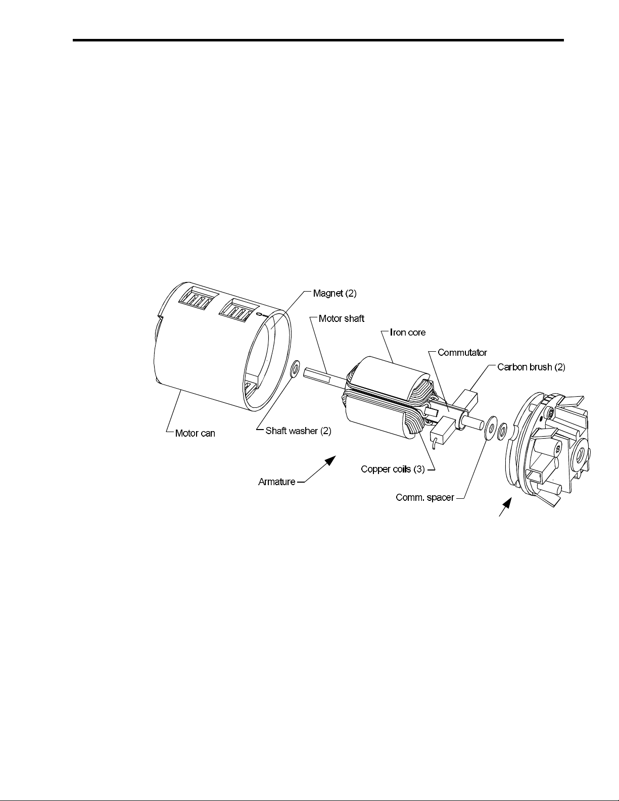
Brushed motors
O-Brushed mo tor op er a tion
Figure 3-1.
In a “brushed” motor, electric current flows through carbon brushes that slide on a
copper commutator ring attached to the motor output shaft as shown in Fig. 3-1. The
commutator ring generally has three segments attached to three coils of copper wire
each wrapped around an iron core. The motor shaft, commutator, coils and iron core
are collectively referred to as the motor “armature”.
As the armature rotates, the brushes conduct current to each segment on the
commutator and through one coil after another. The energized coils produce
magnetic fields that pull the coils toward permanent magnets mounted on the inside
of the motor body (also called the motor “can”). As each coil passes a permanent
magnet, the brush associated with that coil slides onto the next commutator
segment. This de-energizes the coil and energizes the next one in sequence.
LITE MA CHINES 3-3

Op er a tor's Guide Electric Motors
The speed of rotation of a brushed motor is determined by the load on the motor, the
amount of current passing through the coils, the number of turns or winds in the coils
and the operating voltage. Motors running at high voltage are generally more efficient
because less current is needed to generate power, so less energy is lost as heat.
Also, motors with fewer turns have more power and run faster, but are generally less
efficient than motors with more turns.
Brushed motors are easy to manufacture, but are inefficient to operate. Only about
75% of the electric enery entering the motor is converted to mechanical energy. The
rest is converted to heat by the electric resistance of the brushes and by conflicting
O-Brushed eff graph
magnetic fields inside the motor.
As shown in Fig. 3-2, which is a graph of motor efficiency at various motor speeds,
brushed motors are most efficient within a very small speed range. Outside of this
range efficiency drops quickly, and most of the electric energy entering the motor is
converted to heat. When a motor operates outside its efficient speed range the motor
body becomes very hot (sometimes too hot to touch), and the motor coils can burn
out.
Adjustable Timing
Motor coils cannot energize instantly when current is applied. This poses a problem
for brushed motors running at high speed because the coils energize at the wrong
time and generate conflicting magnetic fields that push on the permanent magnets
when they should be pulling (and vice versa). Some brushed motors, such as the
Electro-Fusion motor on your Corona helicopter, have adjustable timing to address
3-4 LITE MA CHINES
Figure 3-2.

Op er a tor's Guide Electric Motors
this problem. To adjust the point at which the brushes touch the commutator
segments, the motor end-bell can be rotated relative to the motor body.
“Advanced” timing gives the coils more time to develop a strong magnetic field so
they can pull on the permanent magnets longer and with less magnetic conflict.
Timing of the Electro-Fusion motor on the Corona helicopter is usually set between
15 and 20 degrees for best results.
Brushless Motors
Brushless motors require no brushes. The copper coils are usually located on the
outer surface of the motor case (instead of on the spinning armature) where they can
be connected directly to a power supply. The permanent magnets are mounted on
and rotate with the output shaft. A small, computerized speed controller turns the
coils on and off at the appropriate time to operate the motor at a particular speed.
Brushless motors are more difficult and expensive to manufacture than brushed
motors, but are more efficient and powerful. With no brushes to burn out, the coils can
carry very high currents. Since the computer operated speed-controller can be
programmed to turn the coils on and off at just the right time, the power loss
O-Brushless eff graph
associated with conflicting magnetic fields is very low.
Figure 3-3.
Efficiencies of good brushless motors approach 90% (that is, 90% of the battery
power going into a brushless motor ends up rotating the output shaft). As shown in
Fig. 3-3, brushless motors also can operate efficiently over a wide speed range. At
such high efficiencies, brushless motors tend to run cooler than brushed motors
because less electric power is wasted as heat.
LITE MA CHINES 3-5

Op er a tor's Guide Electric Motors
Problems with Brushed Motors
Electro-Fusion motors are modified versions of standard 540-size brushed motors.
The original 540-size motors made in the 1980’s produced about 50 watts of power,
but Electro-Fusion motors can produce as much as 150 watts with the same size
brushes. Since the brushes and commutator on modern motors handle more power,
they wear down more quickly. Brush and commutator wear is the primary source of
power loss in brushed motors.
Motor brushes are typically made of carbon, copper and silver, and vary in hardness.
When a brushed motor turns at high speed, the ends of the brushes and commutator
slide against each other and wear down. If the brushes have hard spots, or wear
unevenly, the commutator can also wear unevenly. As the gap between the
commutator and brushes becomes more uneven, small sparks jump between the
brushes and commutator and accelerate the wear of both. This uneven gap also
increases electric resistance.
As resistance goes up, so does the heat generated by the current flowing through the
brushes and commutator. This heat eventually burns the brushes and turns them a
deep blue color. When this happens, brush manufacturers say, certain lubricating
components are burned out further accelerating brush wear.
Once a brush has worn down to the point where it no longer touches the commutator
it must be replaced. If the commutator wears unevenly, it must be resurfaced on a
commutator lathe or the entire armature must be replaced.
Commutator surface finish is possibly the most overlooked problem with brushed
motors because relatively few modelers take apart and inspect their motors. As high
electric currents pass between the motor brushes and commutator, the surface of the
commutator heats up and oxidizes turning a deep black color. This black finish
increases the electric resistance of the commutator/brush connection and consumes
battery power. Removing the black surface finish can restore electric conductivity
and proper commutator function.
Three-Minute Motor Overhaul
For the best long-term performance of your Electro-Fusion motor, service your motor
every six to ten flights using this simple three-minute procedure.
1. Disconnect the flight battery from the speed controller, and the power cables
from the motor, but leave the motor in your Corona helicopter.
2. Remove the motor pinion gear.
3. Pull the brushes out past the end of the brush springs so the brushes do not catch
on the commutator washer.
3-6 LITE MA CHINES

Op er a tor's Guide Electric Motors
O-Re move end-bell
Figure 3-5.
O-Worn brush and comm
4.
Loosen (but do not remove) the end-bell screws. Rotate the end-bell assembly,
and pull it off the motor as shown in Fig. 3-5.
5. Remove the armature from the motor can.
Figure 3-4.
6.
Inspect the brushes. If the brushes are less than 3/16” (5 mm) long, or if the
brushes are burnt and discolored, replace with new ones.
Warning! DO NOT USE REPLACEMENT BRUSHES WITH A SERRATED OR WAVY
RUNNING SURFACE. The serrated surface will cut into the commutator and
damage it.
LITE MA CHINES 3-7

Op er a tor's Guide Electric Motors
7. If the commutator is worn unevenly as shown in Fig. 3-4, replace the entire
O-Comm clean #1
armature with a new one. This will significantly increase motor power.
O-Comm clean #2
Figure 3-6.
8.
If the commutator surface is smooth but dark and discolored, clean it with a
LiteBrite commutator cleaning pad until it is a shiny copper color (six to ten twists
by hand) as shown in Fig. 3-6.
9.
Run a hobby knife in the slots between the commutator segments to remove
loose particles as shown in Fig. 3-7.
3-8 LITE MA CHINES
Figure 3-7.

Op er a tor's Guide Electric Motors
10. If the commutator was clean when you opened the motor, wait a few more flights
before cleaning it the next time. If it was dark and discolored, clean it more
frequently.
11. Clean the inside of the motor can and motor end-bell with a paper towel.
12. Lightly lubricate the motor shaft with Lite Lube heavy oil, and install the armature
in the motor can. Do not oil the commutator segments because the oil will quickly
O-Mo tor tim ing
wear off and stick dirt to the inside of the motor.
Figure 3-8.
13.
Make sure the plastic shaft washers are properly installed, and reassemble the
end-bell to the motor case. Set the end-bell timing mark between 15 and 20
degrees as shown in Fig. 3-8, and tighten the end-bell screws. Do not
over-tighten the end-bell screws or you will bend the internal locking ring.
The Fusion 35 Speed Controller
The Fusion 35 brushed motor speed controller by Castle Creations is a specially
designed microprocessor-based switching controller capable of delivering up to 35
amps of current to your Electro-Fusion brushed motor. The Fusion 35 controller
switches battery current on and off at up to 2800 times per second to control motor
speed.
Battery elimination circuitry (BEC) in the Fusion 35 controller supplies power to the
receiver and servos on your Corona helicopter, and eliminates the need for a
separate receiver battery. Built in filtering capacitors reduce electrical noise and
possible radio interference generated by the motor brushes. A special arming feature
reduces the possibility of accidental motor starting, and a soft-start function smoothly
accelerates the rotor blades to reduce the possibility of gear train damage. If the radio
LITE MA CHINES 3-9

Op er a tor's Guide Electric Motors
receiver loses transmitter signal for more than two seconds, an additional safety
feature turns off power to the motor.
Warning! Electric power systems can be very dangerous. High electric currents can heat wires,
cause sparks and lead to fires and personal injury. DO NOT TO TOUCH EXPOSED
ELECTRIC COMPONENTS, AND NEVER FLY AT A SITE LOCATED NEAR
FLAMMABLE MATERIALS.
Warning! Electric motors are silent, and the main rotor and tail rotor blades of an electric model
helicopter can start tuning unexpectedly or uncontrollably causing serious injury.
ALWAYS USE CAUTION AND MAKE SURE THE TRANSMITTER IS SWITCHED
ON BEFORE CONNECTING THE SPEED CONTROLLER AND BATTERY ON A
HELICOPTER.
Warning! ALWAYS DISCONNECT THE MOTOR POWER CABLES WHEN ADJUSTING THE
RADIO SYSTEM ON A HELICOPTER SO THE MAIN ROTOR BLADES CANNOT
START TURNING UNEXPECTEDLY, AND BE CAREFUL NOT TO TOUCH THE
ENDS OF THE POWER CABLES TOGETHER TO AVOID A SHORT CIRCUIT.
Arming the Fusion 35
To reduce the possibility of accidental starting of the main rotor blades, the Fusion 35
controller will not deliver motor power until it is armed. To arm the Fusion 35, perform
the following steps.
1. Insure that all controller and motor connections are correct, and that the Fusion
35 controller is plugged into the throttle channel on your radio receiver.
2. Turn on your transmitter and make sure the transmitter batteries are charged.
3. Connect your Fusion 35 controller to your battery (you should hear a single beep
from the motor).
4. If this is the first time you are running this controller or receiver, disconnect the
motor power cables and perform a radio range check. If the range check is good,
then reconnect the motor cables.
Warning! DO NOT RANGE CHECK YOUR RADIO WITH THE MOTOR POWER CABLES
CONNECTED. IF THE RECEIVER LOSES TRANSMITTER RADIO SIGNAL
THE MOTOR COULD START UNEXPECTEDLY.
5. Move the transmitter throttle stick to full-low for two seconds. You should hear the
motor beep once.
3-10 LITE MA CHINES

Op er a tor's Guide Electric Motors
6. Move the throttle stick to middle-stick position for two seconds. You should hear
the motor beep again.
7. Move the throttle stick back to full-low for two seconds. You should hear the
motor beep twice and your Fusion 35 is now armed.
Note: If electrical noise becomes excessive, or if radio signal is lost for more than two
seconds, the Fusion 35 will disarm and stop the motor. To rearm, hold the throttle
stick in full-low for four seconds.
Optional RF Filter
The Fusion 35 controller includes built-in filter capacitors to reduce the radio
interference generated by electric motors commonly referred to as “radio-frequency
interference,” “RF noise” or “electrical noise”. DO NOT install additional filter
capacitors between the motor power cables and motor case because this will
interfere with the proper operation of the Fusion 35 controller.
If radio interference becomes a problem, you may install a single 0.1 µF ceramic disk
capacitor between the unused motor solder tabs. This will reduce electrical noise.
After modifying or adding filter capacitors, always test your motor, controller and
radio before flying.
Warning! DO NOT USE TANTALUM OR ELECTROLYTIC CAPACITORS AS ELECTRICAL
NOISE FILTERS BECAUSE THEY CAN EXPLODE AND/OR CAUSE FIRES AND
BURNS.
Cable Connections
The Fusion 35 controller includes a factory-installed Lite Machines connector on the
battery power cable. You must install a corresponding Lite Machines connector to the
wire leads on your battery pack and check the connections to your controller to insure
proper polarity.
Generally, the red (positive) wire of your speed controller should be connected to the
red (positive) wire on your battery pack. Similarly, the black (negative) wires should
be connected to each other. For more information on battery connections, see the
Battery section of the Corona Construction Manual.
The push-on, spade-style connecters on the motor side of your Fusion 35 controller
should fit firmly onto the solder tabs of your Electro-Fusion motor. If the tabs are too
loose or too tight, adjust them carefully with a pliers or small screw driver.
LITE MA CHINES 3-11

Op er a tor's Guide Electric Motors
Warning! IF THE POSITIVE AND NEGATIVE BATTERY CONNECTIONS TO YOUR SPEED
CONTROLLER ARE REVERSED, YOU WILL PERMANENTLY DAMAGE YOUR
SPEED CONTROLLER. THIS DAMAGE IS NOT COVERED UNDER WARRANTY.
Warning! Do not install a fuse between your speed controller and battery. If the fuse blows the
controller and radio receiver will have no power.
Warning! Always perform a radio range check after installing a new speed controller. IF YOUR
RADIO DOES NOT PASS A RANGE CHECK, DO NOT FLY.
Battery Elimination Circuitry (BEC)
The battery elimination circuitry (BEC) in the Fusion 35 controller powers the
airborne radio control system in your Corona helicopter, so you do not need a
separate receiver battery. The BEC will operate with battery packs having up to ten
NiCad cells, but works best with packs of six to eight cells. Packs with over eight cells
develop higher voltages that the BEC must reduce in order to power the radio
receiver and servos. The voltage reduction process generates heat that wastes
battery power.
If you wish to use more than ten cells in your battery packs you must use a separate
battery to power your radio control system. To do so you must first cut the red power
wire from your Fusion 35 controller to the receiver (contact Castle Creations before
doing this). Insulate the exposed end of the cut wire so it does not short circuit the
controller or battery. Be sure to test your radio system before flying your Corona
helicopter after this or any other modification.
Charging Batteries
The Corona helicopter is designed to operate with Electro-Fusion brushed motors
and either six or seven-cell sub-C NiCad battery packs. Electro-Fusion 7 motors work
best with seven-cell packs. Electro-Fusion 6 motors work best with six-cell packs.
The Corona helicopter generally performs best with seven-cell packs because the
added weight increases main rotor speed in hover (which increases stability).
Seven-cell packs also produce higher voltages (8.4 vs. 7.2 volts) which increase
maximum motor power. If you decide to use six-cell battery packs, purchase a
specially configured Electro-Fusion 6 motor to improve flight times.
While NiCad batteries can be fast-charged hundreds of times, it is best to “condition”
new battery packs before use on a Corona helicopter. To condition a new battery
pack, charge it slowly over night at a current of 1/10 of the rated battery capacity. For
3-12 LITE MA CHINES

Op er a tor's Guide Electric Motors
instance, charge a new 2400 mAh battery pack at about 240 mA for ten hours before
flying it on your helicopter or fast-charging it at a high current (3-5 amp) setting.
Since flight times generally run in the range of five to seven minutes, but charging
times run thirty to sixty minutes, it is best to charge several battery packs for each
flying session. For best performance, recharge or peak-charge batteries
immediately before flying, and do not let charged batteries sit overnight. Batteries
that have been left in a fully-charged condition overnight sometimes exhibit an
“overnight effect” which limits the amount of power they can deliver in the morning.
Discharging and recharging these batteries usually reverses this effect.
NiCad batteries that are repeatedly discharged to the same level can develop a
discharge “memory”. Subsequent discharges will tend to stop at this level effectively
limiting battery output. To prevent discharge memory from developing, always
completely discharge your battery packs (by flying your Corona helicopter) before
recharging them or storing them for extended periods of time.
Since NiCad batteries loose power rather quickly at the end of a flight, it is a good idea
to time your flights with a watch. This will insure you are close to the ground when the
batteries get low.
Warning! NEVER STORE BATTERIES IN A CHARGED STATE, OR CARRY CHARGED
BATTERIES TOGETHER OR WITH ANYTHING THAT CONDUCTS
ELECTRICITY. The batteries can short circuit and cause serious fires, personal
injury and property damage.
Battery Chargers
Battery chargers and proper charging technique are very important to the successful
long-term operation of your Corona electric helicopter. A poorly designed or
malfunctioning charger can permanently damage your battery packs in one or two
charges, and reduce the maximum power they produce. Considering that you may
eventually invest hundreds of dollars in batteries to power your radio-controlled
models, it is best to purchase a high quality charger from the start, rather than
purchasing an inexpensive charger first and ruining several expensive battery packs.
Some computer controlled fast-chargers can be connected to a wall outlet or a
standard 12-volt automobile battery, and some display the battery charging
parameters on a computer screen. The computer screen provides important
information about the charging status and capacity of your batteries, and can give
you clues to problems in your electric system such as when a cell in your battery pack
is going bad.
LITE MA CHINES 3-13

Op er a tor's Guide Electric Motors
Flying Weight
Proper flying weight is an important factor in electric helicopter flight. Without enough
weight, the main rotor blades turn too slowly, and stability and control power are
reduced. This is especially noticeable in high winds. For this reason, a heavier
seven-cell battery is preferred over a lighter six-cell battery in the Corona helicopter.
The Corona helicopter is designed to operate efficiently with an Electro-Fusion 7
motor and a seven-cell NiCad battery at a flying weight of about 44 ounces (1250 g).
The Corona flies best with an Electro-Fusion 6 motor and six-cell battery at a weight
of about 42 ounces (1190 g). While the Corona will lift more weight than this, too
much weight can overload a brushed motor and reduce flight times. If you want to lift a
heavy scale fuselage then consider using a brushless motor.
Flight times generally increase by about one second for each gram of weight
removed. Removing a 40 gram (1.5 ounce) canopy will increase flight times by about
40 seconds. Many people practice hovering without a canopy, but it is best to install
the canopy for forward flight so you can tell which way your helicopter is going when it
is far away from you.
3-14 LITE MA CHINES

Op er a tor's Guide Glow-Fuel Engines
G
low-Fuel Engines
Lite Machines gas helicopters are powered by Norvel Vmax-6 and Vmax-7 helicopter
engines. In both engines, the crankshaft is supported by one or more durable bronze
bushings to withstand the side-loads generated by gear driven rotor systems. Each
engine has five directional transfer ports for easier starting and extra lugging power.
The unique throttle/muffler design provides precise throttle control, and traps
exhaust gases inside the cylinder to keep the glow plug hot for a lower, more reliable
idle. The Vmax-7 engine further includes a thermal insulator between the muffler and
crankcase to reduce the flow of heat from the muffler to the engine, and six mounting
lugs to support the increased power.
General Operating Considerations
If you are a beginner, you can cut your learning time in half by locating someone who
knows about Norvel engines and Lite Machines helicopters. Local hobby shops
usually have a list of model airplane/helicopter clubs in your area. Whether you fly a
helicopter or an airplane, you should not fly alone.
Warning! MAKE SURE SOMEONE IS ALWAYS NEARBY TO HELP YOU IF YOU NEED
ASSISTANCE OR HURT YOURSELF WHILE OPERATING YOUR HELICOPTER.
ADULT SUPERVISION IS STRONGLY RECOMMENDED FOR MINORS.
Operating conditions can affect engine life. Helicopters operate close to the ground,
and kick up dust and sand that can scratch the inside of the piston cylinder, or clog the
carburetor making the engine impossible to start or adjust. Avoid flying over loose
dirt, and use a fuel filter to remove dirt from the fuel.
Over time, you will learn to gauge the condition of your engine by the sound it
produces. A high-pitched, even tone usually means the engine is running well. A
slightly lower tone, with an uneven warble may indicate that the engine is too hot or
overloaded. If you have engine problems, refer to the Engine Trouble-Shooting
section of this Operator’s Guide.
Fuel Mixture and Compression
The two most important factors affecting the performance of your Norvel engine are
fuel/air mixture and compression. In operation, air and fuel enter a piston engine
through the carburetor and flow into the cylinder above the piston. As the piston
moves up within the cylinder, it compresses the fuel/air mixture against the hot glow
plug at the top of the cylinder. At a certain point the fuel/air mixture ignites, pushing
the piston down and producing useful power.
LITE MA CHINES 4-1

Op er a tor's Guide Glow-Fuel Engines
The needle valve on the carburetor meters the amount of fuel mixed with the air. Too
much fuel (too “rich”) causes the engine to slow down and lose power. Too little fuel
(too “lean”) causes the engine to over-heat, slow down and lose power. Vmax
engines operate best within a needle valve range of about +1/4 to -1/4 turn.
Proper compression is needed for a reliable idle as well as maximum power.
Compression is adjusted on Vmax engines by inserting or removing thin copper
washers under the glow plug. If compression is set too high, the fuel/air mixture
ignites too soon. This does not affect top-end power appreciably, but the engine may
stop abruptly while idling. If compression is too low, the engine may not produce
enough power for normal flying.
Compression is affected by air density. Anything that increases or decreases air
density increases or decreases compression. The elevation of your flying site and
the local temperature both affect air density and have a major influence on
compression.
As elevation and air temperature increase, air density decreases. To maintain the
same compression at high elevations and air temperatures, the volume in the
cylinder above the piston must be reduced slightly by removing washers from under
the glow plug.
For instance, if you fly at a high elevation (5000 ft or 1524m at Denver, Colorado,
USA), you will use fewer washers under the glow plug than at a lower elevation (700 ft
or 213m at Lafayette, Indiana, USA). Also, if you fly when the outside air temperature
is 75°F (24°C), and the temperature drops to 40°F (4°C) you may need to add
additional glow plug washers before flying again. The large temperature drop will
otherwise affect engine idle because the cold, dense air increases compression.
When air density decreases, less fuel and air enter the engine on each piston stroke.
This means that the engine will not produce as much power at high elevations or high
temperatures where the air is thin. Lift produced by the main rotors depends upon air
density in a similar way. The performance of all aircraft (including full size
helicopters) degrades considerably at high elevations and on hot days.
Hint: The compression rules for Vmax-6 engines are to start with 15% nitro fuel and two
washers under the glow plug. Add an additional washer for each 5% of nitro above
15%, and add an additional washer if the outside air temperature drops below 50°F
(10°C). Remove one washer for every 2000’ (600m) above sea level. For example,
with 25% nitro fuel start with four washers. If the air temperature is 40°F (4.4°C) add
one washer. If flying at 3000’ (900m) remove one washer.
Hint: Vmax-7 engines generally prefer high nitro (25%) and high compression, so use two
to three fewer washers on the Vmax-7 than on the Vmax-6.
4-2 LITE MA CHINES

Op er a tor's Guide Glow-Fuel Engines
The Importance of Clean Fuel
All model glow-fuel engines use a glow plug containing a platinum metal coil. The
platinum metal in the coil acts as a catalyst and ignites the air/fuel mixture in the
engine. To operate properly, the air/fuel mixture must actually touch the surface of
the platinum coil.
If the surface of the coil is coated with anything, even if only a few atoms thick, and
invisible to the eye, the catalytic reaction cannot occur and the engine will run poorly
or not at all. Around ninety percent of all reported engine problems can be traced to
contaminated fuel that coats the glow plug coil and prevents the plug from operating
properly.
Many varieties of rubber will dissolve in glow fuel and quickly foul a glow plug coil.
Use only silicone fuel tubing and plastic (polyethylene, polypropylene or nylon)
containers to store or transfer fuel.
Note: DO NOT USE RUBBER FUEL BULBS, SYRINGES WITH RUBBER PLUNGERS
OR NEOPRENE FUEL LINES TO TRANSFER FUEL INTO YOUR HELICOPTER.
RUBBER WILL CONTAMINATE YOUR FUEL AND FOUL YOUR GLOW PLUG.
Certain brands of model engine fuel contain chemical additives (such as anti-rust
compounds) that can foul glow plugs. Some engines will run on these fuels for a flight
or two, but then loose power. Some engines will not start at all. Do not use fuels that
contain chemical additives such as anti-rust compounds with your Norvel engine.
There is no practical way of cleaning a contaminated glow plug coil. Discard
contaminated glow plugs when changing to a new fuel or after using rubber in the fuel
system.
Hint: Use the Lite Machines Lil’ Squeezer fuel system to quickly fuel and de-fuel your
helicopter. The Lil’ Squeezer fuel system consists of a fuel storage bottle that
protects your fuel from sunlight during storage, and a filtered transfer tube that will
not contaminate your fuel with rubber byproducts.
Synthetic Oils
Some brands of fuel contain synthetic oils that break down at relatively low
temperatures. During a hot, lean run, synthetic oil may not provide sufficient
lubrication to the engine piston and cylinder, and the piston may seize inside the
cylinder or otherwise damage the engine.
Do not use fuels containing only synthetic oil with your Norvel engines. Use fuels
containing castor oil or castor/synthetic oil blends. For instance, if you like Morgan’s
brand fuels, do not use Morgan’s Cool Power fuel with synthetic oil (the green stuff).
Instead, use Morgan’s Omega fuel with castor/synthetic oil blend (the pink stuff).
LITE MA CHINES 4-3

Op er a tor's Guide Glow-Fuel Engines
Breaking-In a New Engine
All piston engines have a break-in period (from ten minutes to over an hour) in which
they do not produce peak power. The piston and cylinder of Norvel engines are
selectively matched at the factory to fit tightly at top-dead-center (where the piston is
at the top of the cylinder). During break-in, the piston and cylinder wear together to
form a perfect fit that will last the life of the engine.
To break-in your new Norvel engine, run it rich (where it runs slowly and unevenly) for
two to three minutes before leaning it out. Then alternately run lean (where it just
starts to speed up and run steadily) for two minutes and then rich for two minutes for a
total of about 20 minutes or two tanks of fuel. This lean-rich break-in procedure not
only wears the surfaces of the piston and cylinder, but also heats and cools the
engine and relieves built-in stresses in the metal of the piston and cylinder.
You may break-in your new engine on a test stand or in your helicopter. Always use a
Lite Machines heat sink on the engine in your helicopter. If you use an airplane style
glow head without the heat sink, your engine will overheat and seize. NEVER run
your engine a test stand without an airplane propeller. The propeller not only cools
the engine, but produces drag which keeps the engine from over-speeding.
Warning! NEVER RUN A HELICOPTER ENGINE ON AN ENGINE STAND WITH ONLY THE
CLUTCH FROM YOUR HELICOPTER OR WITHOUT A PROPELLER. THE
CLUTCH SHOES CAN BE THROWN OFF AT HIGH SPEED AND CAUSE
SERIOUS INJURIES AND PROPERTY DAMAGE.
Engine Starting Summary
This section provides a short summary of proper engine starting procedures for your
Lite Machines helicopter. For more detailed information, refer to the Preferred
Engine Starting Procedure section of this Operator’s Guide.
1. Fill the fuel tank with fuel.
2. Turn on your transmitter and receiver.
3. Open the engine needle valve 2-1/2 turns.
4. Connect your glow plug battery to the glow plug.
5. Start turning the engine with a Lite Machines high-speed electric starter.
6. While still turning the engine with the starter, hold your finger over the carburetor
intake for one second to prime the engine (keep turning the engine with the
electric starter).
7. Remove the electric starter from the engine every two seconds to see if it is
running.
8. Repeat step 6 and 7 as required.
4-4 LITE MA CHINES

Op er a tor's Guide Glow-Fuel Engines
Preferred Engine Starting Procedure
This section contains a detailed, step-by-step procedure for starting the Norvel
engine in your Lite Machines helicopter. Since you will probably want to try flying your
helicopter once the engine is running, you should first read the Main Rotor Stability
and Control and Learning to Fly sections of this Operator’s Guide. Starting the engine
with a helper is strongly recommended. Priming and adjusting the engine are much
easier with the aid of a friend.
1. Bring all necessary equipment with you to the flying field including hand tools like
pliers and wrenches, Lite Machines electric starter and battery, and a supply of
paper towels and spray cleaner.
2. Wear eye and hearing protection.
Warning! ALWAYS WEAR EYE AND HEARING PROTECTION, SUCH AS
HIGH-IMPACT SAFETY GLASSES AND EAR-PLUGS, WHEN OPERATING
YOUR ENGINE. ANYONE HELPING YOU SHOULD WEAR EYE AND
HEARING PROTECTION AS WELL. PROPER EYEWEAR NOT ONLY HELPS
PROTECT YOUR EYES FROM THE SPINNING ROTORS, BUT ALSO FROM
OIL DROPLETS AND DEBRIS THROWN OUTWARD BY THE SPINNING
ENGINE AND CLUTCH.
3. Fill the fuel tank to within 1/4" of the top with model engine fuel containing 15% to
25% nitromethane and castor oil or a castor/synthetic oil blend.
Warning! NEVER FUEL YOUR HELICOPTER WHILE THE GLOW-PLUG BATTERY IS
CONNECTED TO THE ENGINE. SPARKS FROM THE ELECTRIC
CONNECTION COULD START AN INVISIBLE FUEL FIRE.
4. Make sure your radio frequency is clear.
Warning! Two radios cannot operate on the same frequency (channel) at the same time. If
you turn on your transmitter, and it is on the same frequency (channel) as the
transmitter of someone who is already flying, the flying aircraft will lose control
and crash.
5. After you are sure that your frequency is clear, turn on the radio (transmitter first)
and check the operation of all controls. If this is the first flight of the day, perform a
radio range check. With the transmitter antenna fully collapsed, slowly walk away
LITE MA CHINES 4-5

Op er a tor's Guide Glow-Fuel Engines
from the model while moving one of the controls. You should get at least 50 feet
away before losing signal (this distance varies with different radio equipment).
Do not start your engine or fly if the radio fails the range check.
Warning! NEVER RANGE CHECK WITH THE ENGINE RUNNING! THE ENGINE MAY
GO TO FULL POWER AS YOU EXCEED THE OPERATING RANGE OF THE
RADIO.
6. Fully extend the transmitter antenna before starting the engine.
7. If starting the engine for the first time, carefully turn the needle valve clockwise
with a small screwdriver until fully closed, then open it counter-clockwise 2 to
2-1/2 turns.
8. Connect your Lite Machines high-speed electric starter to a 12-volt starter
battery. The starter should spin in the direction shown in Fig. 4-1. If not, reverse
the starter wires on the battery.
(OSIDSTRT)
4-6 LITE MA CHINES
Figure 4-1.

Op er a tor's Guide Glow-Fuel Engines
9. Connect the glow plug to a 1.2 volt battery or a hobby power panel.
Note: Lite Machines SpiraLite Speed and Norvel Freedom XL glow plugs require 1.2
volts. The best way to power a Lite Machines or Norvel glow plug is with a DuBro
Kwik-Start clip. Never wire the glow plug directly to 12 volts (like your car battery)
or the plug will burn out.
10. Connect the glow plug clip to the glow plug on the engine as shown in Fig. 4-1 and
Fig. 4-2.
(OISOSTRT Place ment)
Figure 4-2.
LITE MA CHINES 4-7

Op er a tor's Guide Glow-Fuel Engines
Warning! ALWAYS WEAR EYE AND HEARING PROTECTION. Model engines throw out
oil droplets when running. It is nearly impossible to avoid getting oil on you while
starting the engine.
12. Move the transmitter throttle stick (left stick) to about ½ throttle, and the throttle
trim lever to full. Hold the rotor head with one hand, and tilt your helicopter on its
side with the right skid on the ground as shown in Fig. 4-1 and Fig. 4-2.
13. Spin the engine with the electric starter. Push firmly, but not excessively on the
starter cone as shown in Fig. 4-1.
14. The fuel line from the tank must be full of fuel before the engine will start. While
you spin the engine with the starter, ask your helper to hold a finger over the
carburetor inlet for one second. This will draw fuel from the tank into the engine.
You may need to repeat this procedure several times before the engine will fire.
Hint: If your engine is new it may not turn easily against compression. It will turn more
easily after running for about 30 minutes.
15. If the starter slips on the starter cone, the piston may be hydraulically locked. Do
not force it to turn or you could damage the engine. Remove the heat sink and
glow plug and spin the engine with the electric starter for one second to clear the
excess fuel from the cylinder and crankcase. Replace the glow plug and heat
sink, and clean the oil off the starter cone and the rubber insert on the starter with
a paper towel.
16. If the engine refuses to pop, remove the heat sink and glow plug, and connect the
glow plug to the glow plug clip (be careful, it gets very hot). The entire coil should
glow bright orange (not visible in direct sunlight). If it does not, the glow plug or
glow plug clip may be bad, or the glow plug battery may need charging.
Hint: All glow plugs have a limited useful life. When you suspect that a glow plug is
going bad, replace it with a new one. If engine performance improves, the old
glow plug was bad.
17. When the engine starts, immediately lower the throttle so that the clutch shoes do
not wear against the clutch bell. Be careful, if the throttle is set too high the clutch
will engage and rotate the whole fuselage (and tail rotor) toward you.
18. Remove the glow plug clip, and place your helicopter on its skids on the ground
so that the main rotor can rotate freely.
4-8 LITE MA CHINES
Op er a tor's Guide Glow-Fuel Engines
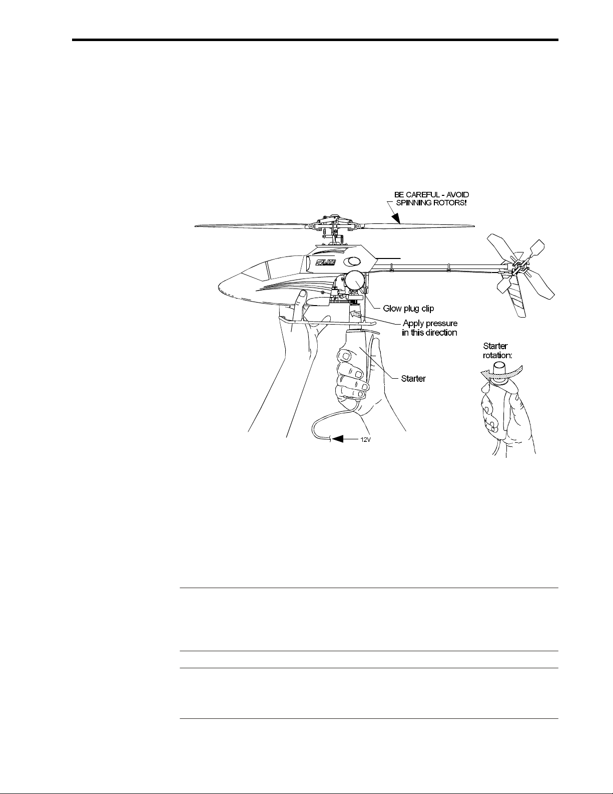
Alternate Starting Method
Fig. 4-3 illustrates an alternate starting method requiring two people − one to hold
and start the helicopter and another to hold and operate the transmitter. This starting
method is illustrated for completeness and because the engine sometimes starts
more easily when held vertically. This method is not preferred because of the
proximity of the rotating rotor blades to the person holding the helicopter.
(OALTSTRT)
Figure 4-3.
Before starting the engine, make sure your helper knows how to operate the controls
on the transmitter, and knows to never move the cyclic controls (right stick) while the
rotors are turning. Hold your helicopter by the canopy and front landing gear struts as
shown in Fig. 4-3 with the main rotor above and tilted away from you. Once the engine
is running, lower the throttle and place the helicopter on the ground.
Warning! THE CYCLIC CONTROLS ARE VERY POWERFUL. KEEP IN MIND THAT THE
HELICOPTER COULD ROTATE OUT OF YOUR GRASP AND STRIKE YOUR
HANDS, ARMS OR FACE. RAPIDLY ROTATING ROTOR BLADES CAN CAUSE
SERIOUS INJURY.
Warning! NEVER, EVER ATTEMPT THE ALTERNATE STARTING METHOD WITH A
LARGER HELICOPTER! THE ROTATING ROTOR BLADES ON A LARGE
HELICOPTER CAN BE LETHAL!
LITE MA CHINES 4-9

Op er a tor's Guide Glow-Fuel Engines
Adjusting Fuel Mixture and Compression
This section describes a step-by-step procedure for adjusting fuel mixture and
compression on Norvel engines.
1. Set your helicopter on the ground with the engine idling. Slide a heavy pole or
wood plank from side to side over the landing gear skids and between the wire
struts in order to weigh your helicopter to the ground. With the helicopter safely
grounded, you can adjust the needle valve at full power. Slowly open the throttle.
If the helicopter lifts into the air, place a heavier weight across the skids.
2. Move the throttle stick and throttle trim lever on the transmitter to full throttle.
3. Carefully reach under the rotor blades and slowly open (screw out) the needle
valve until the engine runs roughly (four-strokes). This fuel/air mixture is too rich.
Warning! MOVE SLOWLY AND CAREFULLY ANY TIME YOU WORK NEAR THE
ROTATING ROTOR BLADES! DO NOT TOUCH THE ROTATING ROTOR
BLADES WITH YOUR HAND OR ARM! ALSO WATCH OUT FOR THE
ROTATING TAIL ROTOR BLADES!
4. Slowly close (screw in) the needle valve. The engine will run faster and
smoother, and the engine sound will increase in pitch. At some point you will hear
it slow down again. This mixture setting is too lean. The optimum needle valve
setting lies about half way between the rich and lean settings. It is best to operate
with a slightly rich mixture since the engine will run cooler.
5. Open (screw out) the needle valve to the optimum point half way between the rich
and lean settings.
6. Close the throttle (throttle trim is still high). The engine should idle smoothly, and
slowly enough that you can hold the main rotor without feeling much clutch drag.
If the engine runs too fast, try reducing throttle trim slightly. If it stops suddenly,
the compression may be too high - add another copper washer under the glow
plug and adjust the needle valve. BE CAREFUL, THE HEAT SINK IS HOT!
Hint: Never hold the rotor head while tightening or loosening the heat sink, because
you could bend the main shaft. Instead, hold the crutch near the tail boom
7. Open the throttle to full, and listen closely to the engine sound. The engine should
smoothly and rapidly increase speed to a maximum. If it sputters and increases
speed slowly or four-strokes (runs rough) it may be slightly rich, so screw IN the
needle valve slightly. If it reaches top speed and then sags or “warbles” it may be
lean, so screw OUT the needle valve slightly.
4-10 LITE MA CHINES

Op er a tor's Guide Glow-Fuel Engines
8. If the needle valve seems to be adjusted correctly but the engine does not
produce much power, it may not yet be broken-in or the compression may be set
too low. Try removing a washer from under the glow plug and readjusting the
needle valve. Handle glow plug washers carefully; they bend easily. Discard
damaged washers.
9. After the needle valve and compression are set, they need not be adjusted for the
rest of the day unless the temperature (air density) changes. If it gets cooler,
adjust the needle valve out (rich) slightly.
Inspecting SpiraLite Speed Glow Plugs
This section refers to the operation of SpiraLite Speed glow plugs, and not to Norvel
Freedom XL glow plugs.
To start your Norvel engine, the coil in your SpiraLite Speed glow plug must glow
bright orange. To test a glow plug, connect it to a glow plug battery with a glow plug
clip, and cup your hands around the plug to keep it out of direct sunlight. BE
CAREFUL, THE PLUG WILL GET HOT QUICKLY. The entire coil should glow bright
orange. If no part of the coil glows bright orange, disconnect the glow plug clip and
check your battery and wire connections.
(OGLOWPLG)
If only a portion of the coil glows orange, then the coil may be touching itself and
creating an electrical short circuit, or touching the glass insulation sealing the top of
the plug and losing heat. In either case, disconnect the glow plug clip and
CAREFULLY separate the loops of the coil from each other, and lift the coil slightly
away from the glass insulation with the tip of a hobby knife as shown in Fig. 4-4. Test
the glow plug again before installing it in your engine.
Figure 4-4.
LITE MA CHINES 4-11

Op er a tor's Guide Glow-Fuel Engines
Electric Starter Effect on Glow Plug
Norvel engines usually start easily. On-going difficulty with engine starting is
sometimes a sign of a field-equipment problem.
Many fliers have a field box with a small 5 Ah motorcycle battery connected to a
power panel which powers the glow plug and electric starter motor. Common
high-torque electric starters designed to start .40 and .60 sized engines are too slow
to start small engines and sometimes draw too much current from the field box
battery.
Even though a glow plug may appear to glow orange (hot) when connected to the
field box battery by itself, it may cool substantially when an electric starter is
operated. This means that the glow plug will stop working just as the starter motor
begins to spin the engine, so the engine may not start. The plug will heat up again
when the starter motor is turned off, making it appear as though the plug is working
properly.
To check for this problem, plug a glow plug clip and a standard electric starter into a
power panel. Connect the glow plug clip to a glow plug, and cup your hands around
the plug to keep it out of direct sunlight. The coil should glow bright orange. Be
careful, the plug will get hot quickly.
Turn on the electric starter. If the field box battery is small, old, or low on charge, the
plug coil will cool and stop glowing. Turn off the starter and the plug will again glow
orange. Also, try operating the starter in one second pulses. Notice that the glow plug
remains hot longer if the starter is pulsed.
4-12 LITE MA CHINES

Op er a tor's Guide Main Rotor Stability and Control
M
ain Rotor Stability and Control
To fly properly and produce maximum lift, the rotor blades of your helicopter must be
adjusted correctly. This section contains information on setting up and tracking the
main rotor blades, and understanding helicopter stability and flight performance.
Refer to the How Helicopters Work section of this Operator’s Guide for more
information on main rotor systems.
Rotor Blade Designations
Lite Machines rotor blades each have a blade number that describes the blade
design and size. Series 1 blades, which are standard on Model 110 and earlier
helicopters, are not marked. Blades having different numbers are incompatible with
each other, so do not use two blades with different numbers on the same rotor head.
Blade designations have thee parts: the series number, length and tip pitch. For
example, the blade designation S2 13 x 0 is read “series 2, 13 inch length, zero
degrees tip pitch”. Blade length is measured from the center of the flapping bolt hole
to the tip of the main rotor blade or from the center of the rotor shaft to the tip of the tail
rotor blade. Blade pitch is relative to the blade grip.
Warning! Series 2 main rotor blades are susceptible to damage by solvents and other
chemicals. DO NOT USE SOLVENTS, SUCH AS ACETONE, TO CLEAN THE MAIN
ROTOR BLADES! BLADES CLEANED WITH SOLVENTS CAN FAIL WITHOUT
WARNING WHEN ROTATING AT HIGH SPEED CAUSING SERIOUS INJURIES.
Use only soap or glass cleaners that are safe for plastic eye glass lenses.
Warning! DO NOT ATTEMPT TO REPAIR DAMAGED ROTOR BLADES. REPAIRED
BLADES CAN FAIL WITHOUT WARNING WHEN ROTATING AT HIGH SPEED
AND CAUSE SERIOUS INJURIES.
Blade Tracking
The main rotor blades on your helicopter must operate at the same pitch angle. If
they do not, one blade will fly higher than the other causing an imbalance and
vibration. This vibration absorbs engine power and can damage the helicopter.
Before adjusting blade pitch, your first need to know which blade is pitched high and
which is pitched low. To do this, stick a 1/4" (6mm) wide piece of highly visible tape
(tracking tape) near the tip of one blade and another about an inch (25mm) from the
tip of the other blade. Don’t worry about causing an imbalance; you will remove the
tape when the blades are tracked.
LITE MA CHINES 5-1

Op er a tor's Guide Main Rotor Stability and Control
O-Tracking out
Figure 5-1.
Start the engine as outlined in the Preferred Engine Starting Procedure section of this
Operator’s Guide. Once the engine is running properly, open the throttle until your
helicopter is just about to lift off (about half throttle). Look at the tips of the rotating
rotor blades (but never place your eyes or face in-line with the blades). If you see two
blade images as shown in Fig. 5-1, then the blades are out of track (one blade is flying
higher than the other).
Note: Before starting the engine, make sure that all radio and starting equipment batteries
are completely charged as per the manufacturer’s instructions. If the radio batteries
die while you are flying, you will lose control and crash.
O-Tracking in
Figure 5-2.
As the main rotor spins, look at the tracking tape and note which blade is flying higher.
Stop the rotor and adjust the length of the two mixing-arm/swashplate pushrods to
increase the pitch of the low blade and decrease the pitch of the high blade.
Remember that if you decrease the length of one of the pushrods, you must increase
the length of the opposite one by the same amount to keep the linkages from binding.
When the blades track properly as shown in Fig. 5-2, remove the tracking tape.
5-2 LITE MA CHINES

Op er a tor's Guide Main Rotor Stability and Control
Dynamic Balancing
If the main rotor blades are tracking properly, but the helicopter still vibrates
noticeably, the main rotor may not be properly balanced. To dynamically balance the
main rotor without removing it from the helicopter, stick a small piece of blade
balancing tape to one of the main rotor blades and run the main rotor at flight speed. If
the vibration level decreases, the extra weight of the trim tape is improving the
balance. If the vibration increases then remove the tape, stick it to the opposite blade
and spin the main rotor again. Try different sizes of trim tape until you find one that
minimizes the vibration. Repeat this procedure for the Arlton Subrotor stabilizer.
Helicopter Stability
Helicopters by their nature are not positively stable. At best, they are neutrally stable.
The concepts of positive stability and neutral stability can be illustrated by placing
He li cop ter sta bil ity
marbles in a bowl and on a table top as shown in Fig. 5-3.
Figure 5-3.
If you nudge the marble in the bowl with your finger, it will roll back and forth and
finally come to rest where it started in the center of the bowl. This is positive stability;
the marble always ends up where it started. If, on the other hand, you push the marble
on the table, it will continue to roll until you stop it, and will sit still until you push it
again. This is neutral stability; the marble stays put until pushed, and keeps moving
until stopped.
Helicopters act like the marble on the table. When correctly trimmed they tend to
remain in one spot until moved, and tend to keep moving until stopped. Unlike the
marble, however, helicopters vibrate and fly in air that is always swirling and rolling.
As a result they do not stay in one place for very long, and require constant small
control inputs to hover over a spot on the ground. The marble on the table would act
more like a helicopter if you shook the table and tilted it back and forth. You would
have to constantly push the marble from different directions to keep it in one spot.
LITE MA CHINES 5-3

Op er a tor's Guide Main Rotor Stability and Control
Adjusting Main Rotor Blade Pitch
Main rotor blade pitch on Lite Machines helicopters is adjusted by interchanging the
blade grips that hold the blades to the rotor head. Blade grips are available in even
numbered two-degree increments from two degrees to six degrees and are called
two-grips, four-grips and six-grips. Odd-numbered grips are not available.
Six-grips increase natural blade pitch by six degrees, and are identified by six raised
dots on the top of the grips. To change blade pitch from six degrees to five degrees,
remove ONE six-grip and install a four-grip (four raised dots). After adjusting the
mixing-arm/swashplate pushrods so that the blades have equal pitch (that is, after
re-tracking the blades), each blade will be pitched five degrees. Note that re-tracking
the blades usually requires two complete turns of the pushrod ball-links for a one
degree change in blade pitch.
Warning! Be careful not to reduce blade pitch so much that the main rotor exceeds its maximum
rated speed since excessive speed could damage the main rotor or engine.
Stability and Climb Performance
Helicopter flight stability and control power is affected by the rotational speed of the
main rotor. At high rotor speeds, the main rotor blades generate high gyroscopic
forces that stabilize the main rotor, and minimize the effects of disturbances such as
wind gusts. The rotor blades can also generate the high aerodynamic (air) forces
needed to forcefully push the helicopter around when the pilot moves the controls.
On fixed-pitch helicopters, helicopter weight and the pitch of the main rotor blades
determines the operating speed of the main rotor, and directly affect stability, control
power and climb performance. High blade pitch generally improves climb
performance, but reduces stability and control power in hover.
This is because rotor blades operating at a high pitch angle produce lift at a relatively
low rotor speed. They do not generate the gyroscopic forces needed for solid
stability, or the aerodynamic forces needed for snappy control. Low blade pitch, on
the other hand, increases rotor speed and stability but reduces climb performance.
The main rotors on Lite Machines helicopters are designed to generate high lift with
very little engine power. High lift is required to fly on hot days and at high elevations
where air density is low. When flying at low elevations (especially near sea level
where air density is high) and with high blade pitch, some helicopters may leave the
ground without adequate rotor speed for acceptable stability and control power.
The usual solution to this problem is to add weight in order to increase rotor speed.
Generally, main rotor blade pitch should be set to the highest value that provides
acceptable stability (usually five degrees when flying near sea level, and six degrees
at higher elevations).
5-4 LITE MA CHINES

Op er a tor's Guide Main Rotor Stability and Control
Big, heavy things (like luxury cars, or larger helicopters) tend to move more slowly
and smoothly than small, light things. This is called the “Cadillac” effect (a Cadillac
being a big luxury car). Small light helicopters respond to air disturbances more
quickly than larger helicopters, and bounce around more in the wind. The Model 110
helicopter is more like a compact car than a luxury car.
Adding one to five ounces [28g to 142g] of weight to a Lite Machines gas-powered
helicopter will significantly improve its flying qualities, especially in windy conditions.
Although it may seem odd to purposefully add weight to a flying machine, the
additional weight requires a higher rotor speed to lift off the ground. This high rotor
speed generates the stability and control power needed to fly in gusting winds.
If, after adjusting blade pitch and weight, you would like more control power, move
the Z-links in the rotor head to the alternate (inner-most) holes on the pitch plate and
mixing arms. This will reduce the stabilizing input of the Arlton Subrotor stabilizer and
increase the control input of the swashplate to the main rotors (thereby decreasing
stability and increasing control power).
LITE MA CHINES 5-5
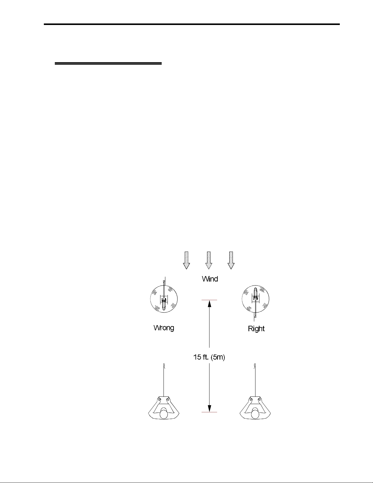
Op er a tor's Guide Learning to Fly
L
earning to Fly
This section describes a three step process for learning to fly your Lite Machines
helicopter. Although it is possible to learn on your own, try to find an experienced
helicopter pilot to help. An experienced pilot can start and tune your engine, trim the
controls, track the rotor blades and copilot your helicopter while you are learning.
Computerized flight simulators are also an excellent way to gain flight experience
without risking your model.
Model flying clubs are a good source of information, and many have flight instructors.
Note, however, that advice from modelers can be highly subjective, so talk to several
individuals and refer frequently to this Operator’s Guide. Also, join the Academy of
Model Aeronautics (AMA). The AMA provides services to modelers and liability
insurance to cover accidents. Many flying fields require an AMA license to fly.
OWIND
Getting Started
Learn to fly on days with little or no wind. If there is a slight breeze, fly with your
helicopter pointed into the wind as shown in Fig. 6-1. It will tend to “weather vane”
(point into the wind) making it easier to fly.
Figure 6-1.
LITE MA CHINES 6-1

Op er a tor's Guide Learning to Fly
Fly your helicopter in open areas outdoors away from people and property such as
buildings and cars. When learning to hover, the best flying sites are clean, smooth
paved surfaces. While not as soft as grass, paved surfaces allow the model to skid
around without leaving the ground. A drawback of paved surfaces is the abundance
of abrasive grit kicked up by the rotor wash that can be ingested by your helicopter
engine and ground into the gears. If you sweep a small area clean with a broom your
helicopter will stay cleaner and last longer.
After mastering the basics of hovering flight, take off from concrete and fly over long
grass. Long grass is much more forgiving than concrete for the occasional
unintended landing.
Training Gear
Use training gear while learning to hover. Training gear consists of two light wooden
dowel rods attached to the landing gear of your helicopter as shown in Fig. 6-2.
Training gear helps prevent tip-overs, and also slows down control response. Cross
two 5/16" x 24" (8mm x 61cm) wood rods to form an “X”, and attach these rods with
rubber bands or nylon ties to the base of each landing gear strut. Glue Ping-Pong
balls to the ends of the rods with thick CA glue to prevent the dowels from catching on
(OTRAINGR)
the ground.
Note:
6-2 LITE MA CHINES
Figure 6-2.
If the rods are too long or too heavy your helicopter will appear unstable in flight
because heavy rods tend to swing under the fuselage on the thin wire landing gear. If
this happens, reduce the size or length of the rods.

Op er a tor's Guide Learning to Fly
Step 1: Learn the Left Stick
The following describes a step-by-step process for learning to fly your Lite Machines
helicopter. The process consist of driving the helicopter on the ground using just the
left control stick on the transmitter until your control actions become unconscious and
automatic. After mastering the left stick to steer, you learn the right stick to hover.
Hint: Are your fingers comfortable on the transmitter control sticks? Stick length and
centering tension are adjustable on most transmitters.
Place your helicopter on a paved surface with the nose pointing into the wind, and the
engine adjusted and idling. Stand about 15 ft (5m) behind the model, and slightly to
the left or right (review Fig. 6-1). If you have an electric helicopter, plug the motor
speed controller into the battery, and arm the speed controller.
Slowly open the throttle (move the left stick forward) to increase rotor speed until the
model is light on the skids, but not actually flying. Move all controls to see if they work
properly. Moving the left stick (tail rotor control) to the left and right should cause the
NOSE to turn left and right. Moving the right stick (cyclic control) should cause the
main rotor to tilt.
Increase the throttle (left stick) slightly and tilt the main rotor forward to pull the
helicopter along the ground. Steer the NOSE with the left stick as the model moves
forward. Do not look at the tail when steering your helicopter.
Drive around without actually leaving the ground until you have mastered steering
with your left hand. Note that the tail rotor control appears to operate backwards
when the helicopter is pointed towards you.
Step 2: Practice Small Hops
While concentrating on the left stick, slowly open the throttle until your helicopter
rises into the air. Pull the left stick back gradually to slow the engine and return to the
ground. Repeat this step until you are accustomed to the throttle control. While
practicing these hops, notice that the nose tends to turn to the left or the right as the
model lifts into the air. Move the left stick in the opposite direction to compensate.
Remember to concentrate on the NOSE when using the left stick to turn. Do not look
at the tail rotor. If the nose rotates to the left, push the stick to the right, and
vice-versa. The objective is to keep the NOSE pointed away from you. Learning the
right stick later will be nearly impossible if the nose turns toward you.
If the nose turns in the same direction on every hop, adjust the trim lever under the left
stick to neutralize the turn. You can also adjust the length of the tail rotor pushrod by
screwing the clevis in or out a few turns (if the nose turns left, shorten the pushrod; if
right, lengthen it). In either case you are changing the pitch of the tail rotor blades
slightly to neutralize the turn.
LITE MA CHINES 6-3

Op er a tor's Guide Learning to Fly
While learning the left stick, it is sometimes helpful to have an experienced flyer
control the right stick (this requires a skilled pilot, since beginners often allow the
model to turn nose-in). Agree ahead of time who does what in case things get out of
control. If your helper on the right stick becomes disoriented, he should tell you
immediately, in which case you should lower the throttle and land as quickly as
possible.
If no one is available to help with the right stick while you concentrate on the left stick,
allow your helicopter to wander a few feet during each hop. If it drifts or tilts in a
particular direction on every hop, adjust the appropriate trim levers next to the right
stick in the opposite direction.
For example, if it always tilts to the right, move the trim lever below the right stick to
the left. You can also adjust the length of the servo pushrods controlling the
swashplate. In either case, tilt the swashplate OPPOSITE to the direction of drift.
Remember that it is impossible to trim any helicopter to sit still in the air. All
helicopters require constant control inputs from the pilot to maintain a stationary
hover.
Step 3: Learn the Right Stick
After mastering altitude and heading control with the left stick, increase the throttle
until your helicopter is at least three feet off the ground (where the air is less
turbulent), and use the right stick to hover over a spot. It will be difficult at first, but try
to keep the model within a small area. If you become disoriented, reduce the throttle
and let the model settle to the ground. Resist all temptations to “punch” the throttle to
full power and climb higher than three feet (you won’t know how to get down).
Keep the nose pointed away from you at all times. When the nose is pointing toward
you (i.e. when you are flying “nose-in”), three of the four controls (fore/aft cyclic,
left/right cyclic and tail rotor) are reversed. Nose-in hovering is difficult for beginners,
and is typically not attempted without considerable experience.
When hovering, concentrate on the TILT of the main rotor disk (the circle made by the
rotating rotor blades) and not on the motion of the helicopter body. The TILT of the
main rotor controls the MOTION of the body. If you concentrate on the motion of the
body, your control inputs will be slightly behind the tilt of the main rotor, and you will
not be able to hold a steady hover.
Warning! WHEN LEARNING TO HOVER, NEVER FLY CLOSER THAN 15 FEET (5 METERS)
TO YOURSELF OR ANYTHING ELSE, OR HIGHER THAN ABOUT 3 FEET (1
METER). YOU COULD LOSE CONTROL AND CRASH CAUSING SERIOUS
INJURY OR PROPERTY DAMAGE.
6-4 LITE MA CHINES

Op er a tor's Guide Learning to Fly
Main Rotor Controls
You will notice a slight time lag between right stick control inputs and the resulting
motions of the model as illustrated by Fig. 6-3. Frame 1 shows a helicopter hovering
with the controls neutralized. In Frame 2, a control input tilts the helicopter to the left
producing a small sideward thrust. Note that the helicopter tilts immediately with the
control. In Frame 3, the controls are neutralized and the helicopter starts moving
sideways. In Frame 4, with the controls still neutralized, the helicopter is moving
rapidly.
It takes time to accelerate a helicopter after the main rotor tilts. Move the right stick in
the desired direction just long enough to tilt the main rotor, then bring the stick back to
neutral. Be patient, and allow the model to accelerate slowly. If you hold the stick too
long, the model will tilt too far, accelerate very quickly and possibly get away from
(OACCELC)
you.
Figure 6-3.
LITE MA CHINES 6-5

Op er a tor's Guide Learning to Fly
(ODECELC)
Figure 6-4.
The same technique used to start a helicopter moving is used to stop. In Frame 1 of
Fig. 6-4, a helicopter is moving sideways with controls neutralized. In Frame 2, a
control input immediately tilts the helicopter to the right creating a small sideways
thrust. Frame 3 shows the controls neutralized, and the helicopter slowing to a stop.
In Frame 4, the helicopter has stopped, and a control input tilts it back to level and into
a steady hover.
As you practice hovering, do not become discouraged if you are not immediately
successful. Hovering a helicopter is one of the most difficult piloting skills to learn,
and NOBODY learns to fly a model helicopter without crashing several times. Most
people require several hours of practice before they can consistently hover over a
spot. Flying a model helicopter is very challenging, and as a consequence, quite
rewarding when you finally get the hang of it.
Hint: Spec ta tors never re ally know what you are try ing to do when you are fly ing your
he li cop ter even when you miss your in tended land ing spot by fifty feet (15 m). If you
wish to im press peo ple, never tell them what you are try ing to do, and they will
as sume you have ev ery thing un der con trol.
6-6 LITE MA CHINES

Op er a tor's Guide Learning to Fly
Forward Flight and Translational Lift
O-Lift
O-For ward flight
Figure 6-5.
When a helicopter is hovering in still air, the air flowing down through the main rotor
(called the “down-wash”) tends to circle around to the top of the rotor and flow
through again as illustrated in Fig. 6-5.
Figure 6-6.
As the helicopter starts moving forward it moves into cleaner, undisturbed air as
illustrated by Fig. 6-6. The main rotor is more efficient in the undisturbed air, and
produces more lift for the same amount of engine power. The increased lift causes
the helicopter to climb.
LITE MA CHINES 6-7

Op er a tor's Guide Learning to Fly
This effect is called “translational lift” because the extra lift is generated as the
helicopter translates (moves forward) through the air. Translational lift affects both
model and full-size, man carrying helicopters. Some early, underpowered full-size
helicopters could not climb above about twenty feet without moving forward to gain
translational lift.
Even when a helicopter appears to be hovering in one spot, wind gusts can blow
away the rotor down-wash and generate translational lift. The increased lift will cause
the helicopter to climb. When the wind stops, the helicopter will suddenly fall. Piloting
a helicopter in windy conditions can be difficult, and requires continuous throttle
control inputs as the wind speed changes.
Tail rotors are also affected by translational lift. Forward motion and wind gusts
cause the tail rotor to generate more lift and turn the helicopter. Windy conditions
therefore require both throttle and tail rotor control inputs in order to maintain a
constant altitude and heading.
Translational lift is much easier to control when the main rotor and tail rotor are
turning at high speed because the speed of the down-wash is much greater than the
speed of the oncoming wind. To increase rotor speed, refer to the Stability, Control
Power and Climb Performance section of this Operator’s Guide.
(OSIDHOVR)
Circles
6-8 LITE MA CHINES
Figure 6-7.

Op er a tor's Guide Learning to Fly
Flying circles is a good way to prepare for forward flight. First practice hovering with
the model turned sideways. It helps to turn your whole body with the model as shown
in Fig. 6-7. Next, try flying circles around yourself as shown in Fig. 6-8. Practice both
left and right circles. Concentrate on maintaining constant altitude (about 4ft or 1.2m)
and distance (at least 15ft or 5m) at first. As you gain experience, fly larger circles at
higher altitudes (do this in a big, open field away from people and obstructions).
(OCIRCLES)
Figure 6-8.
Circles teach you how to control altitude and heading with the left stick, and speed
and position with the right stick. Notice that speed and altitude are related. As the
model picks up speed, it gains altitude (due to translational lift). Note too that the tail
rotor produces translational lift, so you will have to hold right tail rotor control when
the model starts moving forward. You will also discover that forward cyclic control is
required to maintain forward speed (in this regard flying a helicopter in forward flight
differs from flying an airplane).
Once you are comfortable flying circles around yourself to the left and right, try
reversing direction at the end of each circle (turn away from yourself to avoid flying
nose-in). Circle in one direction at an altitude of 10 to 20 feet (3m to 6m), then turn
away and fly the reverse circle.
LITE MA CHINES 6-9

Op er a tor's Guide Learning to Fly
Figure 8’s and Nose-In Hovering
Having conquered hovering and circles, you have most of the basic flight skills
needed for forward flight. The final skill to master is nose-in hovering. When the nose
of the model is pointing toward you, the left/right and fore/aft controls appear to
operate backwards. Your radio is still operating properly, but your frame of reference
O-Fig ure 8’s
is reversed from that of the model.
Figure 6-9.
To prepare for nose-in hovering, practice flying figure 8’s around yourself as
illustrated in Fig. 6-9. Start by flying a right-hand circle. At some point, reverse the
circle by turning to the left. As the model passes in front of you, you will fly nose-in for
a few seconds. This is long enough to experience nose-in flight, but short enough to
avoid becoming disoriented.
Practice both left-hand and right-hand figure 8’s. After mastering figure 8’s, try
hovering nose-in (with the nose pointed directly at yourself). Two new rules will make
this much easier.
The first rule for hovering nose-in is to steer the helicopter by concentrating on
whatever part is furthest away from you, not just the nose. For instance, if the nose is
furthest away concentrate on the nose and your left stick will steer the nose. If the tail
is furthest away concentrate on the tail and your left stick will steer the tail.
The second rule for hovering nose-in is to push the cyclic stick toward the low blade in
order to level the main rotor. For instance, if the main rotor tilts to the left, push the
cyclic stick to the left and vice versa.
6-10 LITE MA CHINES

Op er a tor's Guide Learning to Fly
Descending from Altitude
O-Downwash
Figure 6-10.
If a helicopter descends straight down in still air, it will likely fly into its own
down-wash as illustrated in Fig. 6-10. This is like flying into a strong downdraft and
the helicopter will drop rapidly even at full power.
The technical term for this situation is “descending vortex-ring state”. Pilots of
full-size helicopters refer to it as “settling with power” (although it is very unsettling to
most pilots). If you are ever caught in this situation, immediately fly forward or
sideways to exit the down-wash or you will soon hit the ground.
Another way to avoid settling with power is to fly in circles during descents. It is easier
to judge forward speed when viewing the model from the side while it is circling rather
than from the front when it is coming straight at you.
When decending from altitude, you will notice that substantial forward cyclic
pressure is required to maintain speed in a descent. This is due to the decreased
effectiveness of the cyclic controls as rotor speed is reduced (a characteristic of all
fixed-pitch rotor systems).
Landing
Landings can be a source of tail boom strikes for beginning helicopter pilots.
Helicopter flyers with airplane experience sometimes unconsciously pull back on the
fore-aft cyclic stick as their helicopter nears the ground as though they are controlling
the elevator on an airplane. This tilts the helicopter backward.
LITE MA CHINES 6-11

Op er a tor's Guide Learning to Fly
When the helicopter lands, the fuselage rotates forward parallel to the ground, but
the main rotor blades continue their downward and backward motion and eventually
strike the tail boom. To avoid this problem, apply forward cyclic pressure as your
helicopter touches the ground. Forward cyclic also tends to keep the tail rotor high
when landing in tall grass.
Lite Machines helicopters tend to rotate to the left when you suddenly drop the
throttle after landing. By suddenly lowering the throttle you remove the engine torque
driving the main rotor, but the main rotor and tail rotor are still turning at high speed.
The thrust force produced by the tail rotor pushes the nose of the helicopter to the left.
To make your landings more precise, reduce the throttle slowly after touch-down, or
apply right tail rotor control when reducing throttle. For more information on tail
swing, refer to the Tail Swing and Revo Mix section of this Operator’s Guide.
Piezo Gyro Stabilizers
The tail rotor of most helicopters is connected directly to the main rotor. As a result,
the main rotor and tail rotor change speed at the same rate. This means that changes
in engine torque are roughly compensated for by changes in the thrust of the tail
rotor. As long as throttle changes are made slowly and smoothly, your Lite Machines
helicopter will tend to climb and descend without much tail swing.
The main rotor and tail rotor, however, cannot change speed instantaneously. If you
suddenly increase or decrease throttle, the change in engine torque will cause the tail
to swing. Electronic gyro stabilizers such as piezo gyros sense rotational motion of
the helicopter body and control the tail rotor servo to slow down or stop the rotation.
Gyro stabilizers reduce tail swing considerably, but not completely.
Piezo gyros (which use a piezo-electric crystal) are sensitive to vibration and
temperature changes. A vibrating gyro will send continuous small commands to the
tail rotor servo and eventually wear out the servo. To reduce the likelihood of damage
to the gyro and tail rotor servo, isolate the gyro from vibration with foam mounting
tape or other soft insulation.
In winter, if you store your helicopter in a warm car, and fly in cold air, your piezo gyro
may malfunction as it changes temperature causing your helicopter to lose control.
Always allow your gyro to come to temperature before flying.
Most all electronic gyros have a “gain” control to adjust the amount of gyro
stabilization fed to the tail rotor servo. One way to find the best gain is to start at 50%
of full gain and fly your helicopter. If the nose tends to wander or swing in unwanted
directions, turn the gain up and fly again. If the tail tends to wave back and forth like a
fish swimming, turn the gain down.
Hint: Gyro stabilizers sense only rotational motion. It does not matter where on a
helicopter a gyro is mounted as long as it is orientated correctly and does not vibrate
excessively. Contrary to common wisdom, mounting the gyro near the main rotor
shaft is unnecessary.
6-12 LITE MA CHINES

Op er a tor's Guide Learning to Fly
Adjusting the Arlton Gyro Stabilizer
The dual-gain mechanical Arlton Gyro stabilizer on the Model 110 helicopter greatly
reduces tail swing caused by wind gusts or changes in engine speed. If the tail on
your Model 110 helicopter swings excessively with throttle changes, check that all
parts of the gyro, tail rotor blades and spider slider linkages are oiled and move very
smoothly. Any friction or binding will reduce gyro effectiveness. Also, make sure that
your gyro is set to maximum gain (use upper pin location on spider slider/gyro
spindle).
Excessive tail swing may also mean that your main rotor and tail rotor are rotating too
slowly. Even though the Arlton Gyro stabilizer is quite sensitive, at low speeds the tail
rotor cannot produce enough thrust to keep the tail from swinging. Generally, adding
weight to your Model 110 will increase main rotor speed and tail rotor effectiveness.
In addition, adding weight (like small metal collars) to your gyro paddles can increase
gyro effectiveness at low speeds.
The counterweight bolts on the Model 110 tail rotor blades balance the blades in
flight, and influence the operation of the Arlton Gyro stabilizer. If the gyro is more
effective in one turn direction than in the other, or if the gyro paddles are tilted during
hover, the tail rotor blades may not be properly counter-balanced. Replace the 4-40 x
1/4" bolts with 4-40 x 3/8" bolts or 4-40 x 1/8" setscrews until the gyro rotor spins in a
vertical plane when viewed from behind.
For more information on helicopter stability, refer to the Stability, Control Power and
Climb Performance section of this Operator’s Guide.
Tail Swing and Revo Mix
Radio transmitters designed especially for model helicopters usually have a function
called “revo-mix” which electronically mixes the throttle control with the tail rotor
control. Revo-mix automatically adjusts tail rotor blade pitch each time the throttle
setting is changed. Radio transmitters designed for model airplanes do not have this
function.
An easy way to simulate revo-mix on an airplane radio is to manually move the
throttle (left) stick up and to the left or down and to the right when making rapid throttle
changes. Each day before you go flying, look at the throttle stick and repeat to
yourself “up and to the left”, “down and to the right”, “up and to the left”, “down and to
the right” and you will be able to climb and descend without significant tail swing.
LITE MA CHINES 6-13

Op er a tor's Guide Zen and the Art of Helicopter Maintenance
Z
en and the Art of Helicopter Maintenance
Model helicopters, like their full-size counterparts, spend most of their time shaking
themselves apart. The following sections provide a maintenance schedule and basic
repair techniques for your Lite Machines helicopters.
General Maintenance
Periodically check all parts of your helicopter for breakage, fatigue cracks, loose
screws and normal wear before flying each day and when cleaning up at home. After
the first few flights check all nuts and bolts, especially those holding the engine or
motor to the crutch. The plywood compresses slightly after assembly and the engine
bolts may loosen. Helicopters can also be rough on radio equipment, so check the
servos occasionally for proper operation.
Keep your helicopter as clean as reasonably possible, and keep the radio
compartment and mechanics free of oil and debris. Oil collects dust and dirt that can
cause problems in servo connections and the switch harness. Keep the rotor blades
clean of sand and dirt for best performance.
Other than incorrect assembly, most ongoing problems with helicopters are directly
traceable to poor maintenance. Not only does this lead to unnecessary frustration,
but maintenance failures constitute a serious safety hazard. Periodically review the
following maintenance items and suggested maintenance intervals as part of your
preventative maintenance program.
Engine Maintenance
• Check all mount ing bolts (first af ter 15 min utes run time, then ev ery 20 flights)
• Check heat sink tight ness (ev ery 5 flights, do not hold the ro tor head when tight en ing
the heat sink, you may bend the main shaft.)
• Oil the clutch bell bush ing (one drop of oil on shaft ev ery 5 flights)
• Check clutch bell pin ion for wear (ev ery 30 flights)
• Vi sually in spect for loose en gine backplate (ev ery 50 flights)
• Pe ri odically back flush en gine fuel fil ter (ev ery 50 flights)
• Keep en gine free of grit and de bris
• Keep heat sink fins clean and un ob structed
• Keep car bu re tor screen clean and un ob structed
LITE MA CHINES 7-1

Op er a tor's Guide Zen and the Art of Helicopter Maintenance
Brushed Motor Maintenance
• Clean com mu ta tor with LiteBrite pad (ev ery 6 to 10 flights)
• Check length of brushes, re place if less than 3/16” (5mm) long (ev ery 10 flights)
• Check color of brushes, re place if blue or black (ev ery 10 flights)
• Oil mo tor shaft bush ings with Lite Lube oil (ev ery 20 flights)
• Check for com mu ta tor wear, and re place ar ma ture if nec es sary (ev ery 20 flights)
• Check for dam aged con nec tors and bro ken power ca bles (ev ery 30 flights)
• Check pin ion gear for wear and re place if nec es sary (ev ery 50 flights)
Radio Maintenance
Transmitter
• Watch power me ter when fly ing (NiCad bat ter ies lose ca pac ity with age, and will grad -
u ally lose charge if un used for sev eral days)
• Wipe clean oc ca sion ally us ing soft pa per towel and glass cleaner (when nec es sary)
• Ob serve bat tery charg ing in struc tions (do not over charge)
• Do not ex pose to ex treme tem per a tures
Airborne System
• Range check be fore fly ing (ev ery fly ing day)
• Check for loose/miss ing servo mount ing screws (ev ery 30 flights)
• Check servo travel (ev ery 30 flights, ser vos should move smoothly)
• Check servo speed (ev ery 30 flights, ser vos should move quickly to max i mum throw -
slug gish re sponse may in di cate a low bat tery, bind ing link ages or bad am pli fier)
• Check wir ing for cracks or chaf ing of the in su la tion (ev ery 30 flights, es pe cially where
rub bing on struc ture)
• Check plug con nec tions for loos en ing, and oil or dirt con tam i na tion (ev ery 30 flights)
• Keep all com po nents free of oil
• Ob serve bat tery charg ing in struc tions (do not over charge)
Tail Rotor and Arlton Gyro Maintenance
• Check tight ness of all bolts, set screws and pins (ev ery 10 flights)
• Oil Arlton Gyro sta bi lizer spin dle (ev ery 10 to 15 flights)
• Oil gyro drive link age (ev ery 20 flights)
• Oil spi der and spi der slider (ev ery 20 flights)
• Oil tail ro tor push/pull rod (ev ery 20 flights)
• Check pitch of gyro pad dles (ev ery 30 flights)
• Check gear box for dam age/cracks (ev ery 30 flights)
• Check front and rear bevel gear mesh (ev ery 30 flights)
7-2 LITE MA CHINES

Op er a tor's Guide Zen and the Art of Helicopter Maintenance
Main Rotor Maintenance
• Check tight ness of all bolts, set screws and pins (ev ery 10 flights)
• Check the main ro tor hub and blades for cracks, chipped ends and any other dam age.
Warn ing! DO NOT FLY DAM AGED BLADES. AL WAYS RE PLACE BLADES IN SETS.
• Check swashplate for wear, ad just if nec es sary (ev ery 50 flights)
• Check all link ages for wear, binds (ev ery 50 flights, re place ball links if slop de vel ops)
• Check ball bear ings (ev ery 100 flights, add oil if they move smoothly, re place bear -
ings that feel “gritty” or drag when ro tated)
• Check main ro tor hub, re place if bolt hole is en larged or cracked (ev ery 100 flights)
Warning! DO NOT USE SOLVENTS (SUCH AS ACETONE) TO CLEAN MAIN ROTOR
BLADES! BLADES CLEANED WITH SOLVENTS CAN FAIL WITHOUT WARNING
WHEN ROTATING AT HIGH SPEED AND CAUSE SERIOUS INJURIES. Use only
glass cleaners that are safe for plastic eye-glass lenses.
Warning! DO NOT ATTEMPT TO REPAIR ROTOR BLADES. REPAIRED BLADES CAN
FAIL WITHOUT WARNING WHEN ROTATING AT HIGH SPEED AND CAUSE
SERIOUS INJURIES.
Power Train Maintenance
• Check all bolts and set screws on bear ing col lars and gears (ev ery 10 to 20 flights)
• Oil main spur and tail ro tor crown gear teeth (ev ery 10 to 20 flights)
• Check all gear meshes (ev ery 30 flights)
• Check for wear on gear teeth (every 30 flights)
Field Equipment Maintenance
• Make sure 12 volt bat tery for elec tric starter is fully charged (ev ery fly ing day)
• Check glow-plug clip wires for breaks or other signs of wear (ev ery 30 flights)
• Clean oil off field equip ment (ev ery fly ing day, oil at tracts dirt and is even tu ally trans -
ferred to ev ery thing in your flight box)
LITE MA CHINES 7-3

Op er a tor's Guide Zen and the Art of Helicopter Maintenance
Making Repairs with CA and Glass Fiber
The following procedure describes how to make an instant fiberglass patch on a
broken part like a wood crutch using CA glue and fiberglass tape.
Warning! NEVER TRY TO REPAIR THE FLEXIBLE PLASTIC PARTS OR ROTOR BLADES
OF YOUR HELICOPTER! No type of glue (including CA glue) will stick to the plastic,
and THE REPAIRED PART WILL FAIL IN OPERATION AND POSE A SERIOUS
DANGER!
1. Assemble the necessary supplies: thick CA glue, CA accelerator, heavy
fiberglass cloth, coarse sandpaper, a scissors and a small plastic bag (like the
parts bags in your helicopter kit).
2. Clean the broken part with window cleaner to remove any oil. Sand an area ½”
(13mm) around the break with coarse sandpaper or a grinder to scratch the
surface and remove any paint.
3. Cut a piece of heavy fiberglass cloth to fit the patch area.
Hint: Fiberglass cloth does not easily bend around sharp edges. If you are repairing
the plywood crutch on your helicopter, apply a separate patch to both sides of the
plywood rather than trying to bend a single patch around an edge.
4. Hold the break tightly closed and apply thick CA glue to the surrounding sanded
area.
5. Lay the fiberglass cloth patch over the CA glue, and fill the weave in the cloth with
more CA glue.
6. Place the plastic bag over your thumb and spray CA accelerator on the outside of
the plastic bag. Press the plastic bag down onto the fiberglass patch and the CA
glue will immediately harden.
7. Remove the plastic bag and you will have a smooth fiberglass patch. Trim the
rough edges of the patch with a hobby knife or grinder.
Warning! WEAR A FILTER MASK AND DO NOT INHALE FIBERGLASS DUST! The
sharp glass fibers in the dust can settle in your lungs and cause long term health
problems.
7-4 LITE MA CHINES

Op er a tor's Guide Zen and the Art of Helicopter Maintenance
Making Repairs with CA and Baking Soda
Common baking soda (sodium bicarbonate) is a remarkably good filler material for
thin CA glue. Baking soda not only fills small gaps, but also accelerates the
hardening of CA glue (like liquid CA accelerator).
To make a rapid repair with baking soda, simply clean and abrade the surface, cover
or fill the area with baking soda to a depth of about 1/16” (1mm) and apply several
drops of thin CA. The CA will soak into the baking soda and harden almost instantly.
Fill deep holes in 1/16” (1mm) layers to insure that CA soaks through all of the baking
soda.
Note that baking soda repairs are easy to shape with a hobby knife or sand paper, but
are not as strong as fiberglass cloth. For high strength repairs, use fiberglass. For
moderate strength repairs and to fill gaps, use baking soda.
Fixing a Bent Tail Boom
Tail booms are frequently dented by the main rotor blades during crashes or hard
landings. Small dents will not affect the flight qualities of your Lite Machines
helicopter. A bent boom can usually be straightened by hand several times before
being replaced. Small dents can be removed by pushing a 3/8” (10mm) wooden
dowel rod into the boom to smooth out the dents. Generally, replace a tail boom at the
first signs of cracking, or when the boom becomes so ugly you cannot stand it.
Straightening a Bent Main Shaft
Main rotor shafts are bent occasionally during crashes. The bend will almost always
occur where the shaft is supported by the upper ball bearing.
To straighten a main rotor shaft, first disconnect the swashplate control linkages and
remove the main rotor head from the shaft. Attach a pointer (made from a clothespin
and paper clip wire) to the top edge of the crutch and set the pointer next to the top
end of the main shaft. Rotate the shaft until you can see the direction in which the
main rotor shaft is bent. Lightly press on the top end of the main shaft with your thumb
in the opposite direction of the bend, then check the shaft for straightness again.
LITE MA CHINES 7-5

Op er a tor's Guide How Helicopters Work
H
ow Helicopters Work
By Paul Arlton
This section provides a brief technical explanation of certain aspects of helicopter
flight control systems, and is included in this Operator’s Guide for your interest only.
It is not necessary to read this section in order to build or fly your Lite Machines
helicopter.
Introduction
With all of their spinning gizmos and mechanical linkages, model helicopters are
intrinsically interesting. Unfortunately, they can also be very expensive and
complicated, and traditional model helicopters are not well suited for the average
modeler. They usually require considerable patience and understanding (mostly
from the other members of your family), and a credit card with a high limit.
Lite Machines helicopters are meant to be different from traditional model
helicopters, and their designs reflect the personalities of the people who were
involved in their development: Dave Arlton, Paul Klusman and me, Paul Arlton.
As much as I enjoy helicopters, I don’t have the patience necessary to be successful
with them. Even with airplanes, I rarely allocate adequate time for my projects, and
end up immensely frustrated when things don’t work. So I concentrate on projects
that are simple, inexpensive and less likely to end up as a psychological disaster. I
am perfectly content with a simple two-channel Cox .049 powered F6F Hellcat that I
built from scratch in a weekend from Styrofoam and Econocote for about $10.
My brother, Dave, is just the opposite. He revels in the complex and esoteric. In 1987,
with dreams of spinning rotors and autorotations impairing his ability to reason
objectively, he purchased a Shlüter Champion helicopter for about $1,600 (that’s in
1987 dollars). At the flying field he would wander aimlessly for 30 minutes, building
enough courage to attempt his first flights of the day. I never had that problem with my
F6F.
One day in 1988, our friend Paul Klusman brought over a rubber-band powered
model helicopter he had designed. As I watched it fly, I though it must be possible to
build something similar for radio control. Later, in 1990, after two years of
experimentation and development work in the basement, we had a flying model
helicopter powered by a Cox .049, and sought a company to manufacture and market
it. When Dave and I could not find a suitable company, we decided to build one
ourselves. With the help of our parents, we incorporated Lite Machines in the Purdue
University Research Park in 1991.
As we developed the prototypes that would eventually become the Model 100, we
learned a lot more about model helicopters than we really wanted to know. Because
we started with little formal education on the subject, however, we often argued about
LITE MA CHINES 8-1

Op er a tor's Guide How Helicopters Work
details without completely understanding the big picture. It would have been handy to
start with a basic understanding of helicopters so that we could have discussed some
of the problems more intelligently.
The following sections provide a brief introduction to helicopter flight dynamics for
those who are just starting and want to know a little more.
Background and History
Helicopters are flying machines with the ability to hover and fly forwards, backwards,
and sideways. This agility stems from the multiple capabilities of the main rotor
system. Since the invention of helicopters in the early 1900’s, considerable effort has
been expended advancing helicopter technology, with a substantial percentage of
that effort concentrated on the main rotor system.
While the technology of full-size helicopters progressed for decades, model
helicopters remained impractical for lack of suitable engines, radio control
equipment, and construction materials. As the state-of-the-art in full size helicopters
advanced in the 1950’s and 1960’s, many novel model helicopter designs were
developed, but none proved practical. Model helicopter designers often copied the
designs of full-size helicopters without understanding the basic differences between
full-size and model aircraft. As a result, scaled-down model helicopters were
typically unstable, uncontrollable and underpowered.
In the 1970’s hobbyists (most notably Dieter Shlüter in Germany) developed the first
practical model helicopters. Lighter radio control equipment, more powerful engines
and systematic engineering all contributed to early successes. Much of model
helicopter design, however, is rooted in tradition. Even though helicopter technology
has advanced considerably since that time, the designs and design philosophies of
that era are still in widespread use.
Because the main rotor system of a helicopter is capable of performing so many flight
functions, it is usually very complex mechanically. Model helicopters currently
available contain myriad pushrods, mixing arms, bellcranks, ball joints, and
expensive ball bearings, and the trend has been toward higher complexity and
prices. High complexity and cost keep many model enthusiasts away from
helicopters.
Standard Helicopter Configuration
Both model and man-carrying helicopters are commonly designed with a large main
rotor which lifts the helicopter into the air. A smaller tail rotor mounted at the end of a
tail boom counteracts the torque produced by the main rotor and steers the
helicopter. Both main and tail rotors are driven by an engine usually located within the
helicopter fuselage (body) near the main rotor shaft. A streamlined fuselage shell
8-2 LITE MA CHINES

Op er a tor's Guide How Helicopters Work
often covers the front half of the helicopter, but does not always extend back to the tail
rotor because of the added weight and complexity of attaching the rear shell to the
rest of the helicopter.
From a distance, the main rotor of a helicopter looks superficially like a large
propeller sitting on top of the fuselage. The main rotor blades act something like a
propeller or fan, and move large amounts of air downward creating a force that lifts
the helicopter upward.
Helicopter rotors, however, operate in a manner completely different from propellers
on an airplane. Unlike propellers, they are designed to move through the air
sideways. In order to control a helicopter in horizontal flight the pilot causes the main
rotor to tilt slightly in one direction or another. The offset lift force produced by the
tilted main rotor causes the helicopter to move in the direction of the tilt.
Main Rotor Control
OBCKGD01
To understand how helicopter main rotor systems work, it is easiest to begin with a
simplified representation of a rotor system. Fig. 8-1 shows a schematic rotor blade
rotating about a shaft. The rotor blade pitch axis runs down the length of the rotor
blade. Blade pitch (also called “angle of attack”) is considered positive when the
leading edge of the rotor blade is rotated upward about the pitch axis. The
aerodynamic lifting force produced by a rotor blade is related to blade pitch.
Increased (positive) pitch corresponds to increased lift.
Figure 8-1.
LITE MA CHINES 8-3

Op er a tor's Guide How Helicopters Work
As shown in Fig. 8-2, in addition to a pitch axis, rotor blades are generally hinged near
the rotor hub to allow the blade to flap up and down and swing forward and backward.
This allows the rotor blades to react to the constantly changing aerodynamic and
gyroscopic forces encountered in flight. Without these hinges the rotor blades would
likely be unstable, and would need to be built stronger and heavier to withstand
OBCKGD02.
in-flight forces
Helicopter dynamics are substantially different from airplane dynamics. The rotating
main rotor on top of a helicopter acts like an immense gyroscope. As such, the rotor
obeys the physical laws of gyroscopes. The basic operating principles of gyroscopes
are not obvious, so read the next sentence over a few times because this
rule-of-thumb is the key to understanding gyroscopes and helicopters.
Forces applied to tilt a rotating gyroscope produce motion 90 degrees later in
the direction of rotation.
Why? Because the gyroscope is rotating. If the gyroscope was not rotating, the
forces would cause it to tilt where the forces were applied. Since the gyroscope is
rotating, it starts to tilt where the forces are applied, but the rotational motion
effectively carries the tilting motion along with it. The maximum tilt actually occurs 90
degrees later in the direction of rotation.
8-4 LITE MA CHINES
Figure 8-2.

Op er a tor's Guide How Helicopters Work
OBCKGD03
Figure 8-3.
The rule-of-thumb for gyroscopes is illustrated by Fig. 8-3. If aerodynamic forces are
applied to a pair of rapidly rotating rotor blades, the rotor blades, acting under the
laws of gyroscopes, will flap 90 degrees later in the direction of rotation. This flapping
will be seen by an observer as a tilt of the entire rotor disk (when a rotor rotates at high
speed, it is difficult for an observer to discern individual rotor blades, and the rotor
appears to be a transparent disk). The aerodynamic forces are created by changing
the pitch of the rotor blades, or by air turbulence.
On Lite Machines helicopters, to tilt the rotor disk backward the main rotor blades are
pitched to a high angle of attack as they pass around the right side of the fuselage and
to a low angle of attack around the left side of the fuselage. The aerodynamic forces
produced by this difference in angle of attack cause the blades to flap upward 90
degrees later over the nose and downward over the tail boom thereby tilting the rotor
disk backward.
Why 90 degrees, and not some other angle like 62 degrees or 127 degrees? The
answer is fairly technical, and involves the concept of mechanical resonance which is
a kind of back-and-forth motion such as the motion of a weight swinging on the end of
a piece of string. But, forgetting the technicalities, think of it like this: there is no good
reason why the point of maximum flapping should be any closer to one of the forces
than to the other. If two equal forces are located opposite each other (180 degrees
apart), then the maximum flap angle should occur right in the middle at 90 degrees.
LITE MA CHINES 8-5

Op er a tor's Guide How Helicopters Work
Since the main rotor on a helicopter rotates while the fuselage or body of the
helicopter does not, some mechanism is needed to transmit control commands from
the non-rotating pilot to the rotating main rotor blades. One such mechanism is called
a swashplate which is essentially a large ball bearing assembly surrounding the main
rotor shaft. In order to tilt the main rotor, the pilot moves linkages attached to the
lower half of the swashplate. The upper half of the swashplate is connected through
linkages to the rotor blades.
Traditionally, the pilot of a full-size helicopter controls the main rotor by manipulating
a joystick called the “cyclic” control located in front of the pilot, and a lever called the
“collective” control located to the left of the pilot. Cables, pushrods, and bellcranks
connect the cyclic and collective controls through the swashplate to the pitch controls
of the main rotor blades.
Main rotor systems of most radio-controlled model helicopters operate in a manner
similar to full-size helicopters. The pilot manipulates small control sticks on a
hand-held radio transmitter which in turn sends commands to servo actuators
located within the flying model. Pushrods and bellcranks connect the servos through
the swashplate to the pitch controls of the main rotor blades.
To bank the helicopter to the right or left, or move forward or backward, the rotating
rotor blades are pitched upward as they pass around one side of the helicopter and
downward around the other. This is called “cyclic” pitching since the rotor blades
cycle up and down as the rotor rotates. The difference in lift produced on either side of
the helicopter causes the main rotor blades to flap up and down, and the rotor disk
appears to tilt. The tilted rotor disk produces a sideways thrust force that then pushes
the helicopter in the direction of the tilt.
The large size and high inertia of most helicopter rotors means that they cannot
change speed quickly. For this reason, they are usually designed to operate at a
nearly constant rotational speed at all times. To control main rotor lift, the main rotor
blades are pitched upward or downward in unison. This is called “collective” pitching
since all rotor blades move together. The change in pitch, and associated lift force of
the rotating rotor blades causes the helicopter to gain or loose altitude.
Some small model helicopters (such as the Lite Machines Model 110) rely on
variable engine speed instead of collective blade pitch for altitude control since main
rotor thrust is proportional to rotor speed as well as blade pitch. The main rotor blades
on these models are typically built at a fixed pitch (relative to each other) and are light
enough to react quickly to changes in engine speed. The primary advantage of
fixed-pitch rotors on models is reduced mechanical complexity and cost.
Main Rotor Stability
Flight stability is often a problem for small helicopters. To improve stability, weighted
stabilizer bars (flybars) are usually incorporated into model helicopters, but are
uncommon on modern full-size helicopters. First patented by Stanley Hiller Jr. in
1953 and refined for use on models by Dieter Shlüter in 1970, these flybars are tipped
with aerodynamic paddles (Hiller paddles), and are connected through linkages to
the swashplate and main rotor blades.
8-6 LITE MA CHINES

Op er a tor's Guide How Helicopters Work
Because the pilot’s controls are attached to the flybar, and not directly to the main
rotor blades, Hiller control systems naturally exhibit a slight control delay. A hybrid
stabilization system referred to as the Bell/Hiller system incorporates additional
linkages to mix direct rotor blade control with flybar stabilization. The Bell/Hiller
system responds quickly because pilot control commands are transmitted directly to
the main rotor blades, while the system is stabilized by a Hiller-type flybar and
paddles.
A major drawback of flybars and paddles is increased aerodynamic drag. The
circular cross-section flybar wire supporting Hiller paddles can produce more drag
than the paddles. Moreover, since Hiller paddles are typically configured to operate
at a zero angle of attack relative to the rotor head, and since air passing through the
rotor is almost always flowing downward, Hiller paddles can actually operate at a
negative angle of attack with respect to the incoming airflow. In this way, Hiller
paddles actually contribute negative lift.
The unusual Arlton Subrotor stabilizer blades on Lite Machines helicopters serve a
triple purpose. As part of the main rotor control system, they amplify pilot control
commands to the main rotor blades. As part of the stability system, they act to keep
the main rotor spinning in a constant plane in space. As rotor blades, they can
produce lift that reduces or eliminates the reversed airflow commonly found near the
rotor hub.
Retreating-Blade Stall
Retreating-blade stall (also referred to as “asymmetric lift”) affects helicopter rotors
that are moving forward (translating). As A Lite Machines helicopter moves forward,
the blade swinging forward over the right side of the helicopter (the advancing blade)
experiences a higher air speed than the blade swinging backward over the left side of
the helicopter (the retreating blade). At high airspeeds the advancing blade
generates high lift, while the inner portions of the retreating blade actually move
backward relative to the oncoming wind, and much of the retreating blade is stalled.
The airflow around the stalled retreating blade is very turbulent and the blade does
not generate much useful lift.
Following the rule-of-thumb for gyroscopes, the high lift generated by the advancing
blade, and the low lift produced by the retreating blade will cause the main rotor disk
to tilt backward away from the oncoming wind. In order to keep a helicopter moving
forward at high speed, the pilot has to maintain forward pressure on the transmitter
fore-aft cyclic control stick to reduce asymmetric lift and tilt the rotor disk forward.
Retreating blade stall can also be induced by changes in rotor speed. Since Lite
Machines helicopters have a fixed-pitch (variable-speed) main rotor, the speed of the
rotor must change to control altitude. When descending from altitude the speed of the
main rotor is reduced substantially, but forward flight speed does not change.
Without pilot intervention, the Lite Machines helicopters will pitch up and fly
backwards due to retreating blade stall. It should be noted that helicopters with
LITE MA CHINES 8-7

Op er a tor's Guide How Helicopters Work
collective-pitch (constant-speed) main rotor systems do not normally experience
retreating blade stall during descents, and do not require as much forward stick
pressure to maintain forward speed.
Anti-Torque Systems
The torque (reaction force) created by rotating the main rotor of a helicopter in one
direction tends to cause the body to turn in the opposite direction. When trimmed for
steady hovering flight, the tail rotor at the end of the tail boom creates enough thrust
force to balance the torque produced by the main rotor so that the helicopter
maintains a constant heading. Decreasing or increasing the thrust force of the tail
rotor causes the helicopter to turn in one direction or the other.
The pilot of a full-size helicopter controls the tail rotor by manipulating foot pedals
located within the cockpit. The pilot of a model helicopter manipulates control sticks
on a radio transmitter which in turn sends commands to servo actuators located
within the flying model. Cables, pushrods, and bellcranks connect the pedals or the
servos to the pitch controls of the tail rotor blades. The pilot adjusts the pitch and
associated thrust force of the rotating tail rotor blades to turn the helicopter.
Although a number of modern anti-torque systems (such as blown tail booms and
shrouded fans) have been developed, tail rotors have not changed materially for over
25 years. For reasons of structure and simplicity, and to minimize actuation forces,
tail rotor blades traditionally employ symmetrical cross sections such as a NACA
0012 airfoil, and simple constant-chord blade shapes. While easy to build, these
rotors do not utilize power very efficiently. Since helicopters have relatively low
payload capacities, even small increases in rotor performance can result in large
percent changes in payload capacity.
Cambered (curved) airfoils can substantially increase the lifting potential of a rotor
blade. Cambered airfoils, however, have a drawback: the curvature of the airfoil
causes the airfoil to pitch downward toward negative angles of attack. This pitching
tendency can cause the rotor blade to twist and exert high loads on the blade
pitch-control linkages (and consequently to the pilot’s legs in full-size helicopters, or
to the servos in model helicopters).
The unique swept tail rotor blades on Lite Machines helicopters balance the
aerodynamic twisting forces of high lift cambered airfoils with other forces. They
operate something like canards (little forward wings) on an airplane by balancing the
negative twisting force of cambered airfoils with a positive lift force located in front of
the blade pitching axis. Small counterweights at the blade root also help to balance
the aerodynamic forces. As a result, tail rotor power requirements are lower, and
control linkage forces are reduced by as much as 80%.
8-8 LITE MA CHINES

Op er a tor's Guide How Helicopters Work
Gyro Stabilizers
In general, maintaining a constant heading in hover or low speed flight can be a
difficult business for a helicopter pilot. To counterbalance the constantly changing
forces on the helicopter fuselage produced by changes in engine torque and
atmospheric conditions such as wind gusts, the pilot must continually manipulate the
tail rotor controls. This is especially true for models because of their small size and
low mass, and the resulting tendency to react rapidly to disturbances.
To solve this problem, practically all modern model helicopters are equipped with
some sort of auxiliary stabilization system. A gyroscopic stabilizer, or “gyro”, is a
device on a helicopter that senses turning motion, and then automatically controls
the tail rotor servo and tail rotor to slow down or stop the turn. Basically, a gyro keeps
the tail of a model helicopter from swinging so that the pilot can concentrate on other
things.
Piezo gyros contain a piezo-electric crystal and an electronic circuit that is sensitive
to rotational motion. Piezo gyros are also sensitive to vibration and temperature
changes. Since piezo gyros are connected to and constantly control the tail rotor
servo, it tends to wear out more quickly than servos attached to other flight controls.
The Arlton Gyro stabilizer shown in Fig. 8-4 is a simple mechanical mechanism that
attaches to the tail rotor of a helicopter and performs the same function as an
electronic gyro. It operates under the same physical laws governing
electro-mechanical gyros (see the rule-of-thumb for gyroscopes under the Main
Rotor Control heading in this chapter), but it is driven and amplified mechanically
rather than electronically. It weighs only about ½ ounce (14 gm) and consumes no
battery power. Since the Arlton Gyro stabilizer controls the tail rotor blades directly, it
does not affect the workload of the tail rotor servo.
The aerodynamic paddles and gyro hub on the Arlton Gyro stabilizer are supported
for rotation by a gyro spindle (see Fig. 8-4) which is free to tilt about two small, steel
pivot pins. The pins are connected to a gyro mount which is secured to the end of the
tail rotor pushrod on the Model 110 helicopter. The pushrod extends through the
hollow tail rotor shaft (see Fig. 8-5).
When the body of the helicopter turns, the pivot pins turn with the body and apply
forces to the gyro spindle to tilt the paddles about a vertical axis in the direction of the
turn. Following the rule-of-thumb of gyroscopes, the paddles actually tilt 90 degrees
later about a horizontal axis. As they tilt, they displace linkages (including the spider
slider and the pitch-change spider) which change the pitch of the tail rotor blades.
This change in blade pitch modifies the thrust produced by the tail rotor, and slows or
stops the turning motion of the helicopter.
LITE MA CHINES 8-9

Op er a tor's Guide How Helicopters Work
OEXPGYRO
(OGYRCTRL)
8-10 LITE MA CHINES
Figure 8-4.
Left to themselves, the gyro paddles will remain tilted unless the helicopter starts
turning in the opposite direction. But the small Z-links that connect the paddles to the
tail rotor are angled slightly at one end (see Fig.8-4) so that the pitch of the paddles
changes as the paddles tilt. This change in paddle pitch generates aerodynamic
restoring forces on the paddles that push them back to their initial, untilted orientation
(helicopter buffs will understand that this is similar in concept to delta hinges on a
main rotor). So, essentially, turning motion of the helicopter causes the paddles to tilt,
and the tilted paddles then push themselves upright.
It is interesting to note that the gyro mount may be oriented on the tail rotor pushrod
so that the pivot pins are not horizontal. In this configuration, the gyro will sense
rolling motions as well as turning motions. In this way the gyro can be set to
coordinate turns by modifying the thrust of the tail rotor when the helicopter rolls. This
is something like adding rudder when turning an airplane with ailerons.

Op er a tor's Guide How Helicopters Work
OPLTCTRL
Figure 8-5.
The Arlton Gyro stabilizer works automatically without any input from the pilot, but at
some point the pilot may wish to trim the tail rotor or turn the helicopter without
interference from the gyro. To turn the helicopter, the pilot controls the tail rotor servo
which moves the tail rotor pushrod back-and-forth. As shown in Fig. 8-5, the tail rotor
pushrod passes from the right side of the gearbox completely through the hollow tail
rotor shaft and extends out the left side. Since the gyro is mounted to the end of the
pushrod, the entire gyro assembly moves back-and-forth along with it.
The rule-of-thumb for gyroscopes states that a gyro will react to tilting forces, but the
rule says nothing about moving the whole gyro back-and-forth. In fact, linear
(non-tilting) motion of the gyro has no effect on the gyro whatsoever. This means that
the gyro will not tilt, and will not change the pitch of the tail rotor blades when the pilot
moves the tail rotor controls. The gyro will operate only when the body of the
helicopter turns.
When the helicopter starts to turn under pilot control, the gyro will tilt about 20
degrees before reaching an end limit. Once there, it will no longer be able to modify
the pitch of the tail rotor blades, and so it will stop opposing the turn. This means that
after the helicopter turns a certain amount, the pilot will have amplified tail rotor
control authority (something like having dual-rates on the transmitter).
LITE MA CHINES 8-11

Op er a tor's Guide How Helicopters Work
The aerodynamic and mechanical characteristics of the tail rotor have a substantial
impact upon the operation of the Arlton Gyro stabilizer. The actuating power of a
purely mechanical gyro stabilizer is determined by the rotational speed, size and
mass of the gyro paddles and gyro hub. Given a particular tail rotor rotational speed,
high actuation forces require large diameter and/or heavy gyro paddles. Tail rotor
blade actuation forces, therefore, must be kept low to minimize the size and weight of
the gyro.
Undercambered airfoils can greatly increase the thrust of the tail rotor, but the
pitching forces generated by undercambered airfoils can also exert high loads on the
tail rotor blade pitch-control linkages, and consequently on the gyro. The tail rotor
blades on the Model 110 helicopter are aerodynamically and centrifugally balanced
to operate in conjunction with the Arlton Gyro stabilizer. Small weights are provided
at the root of each blade for fine tuning the pitching forces. If the blades are not
completely pitch-balanced, the gyro will tilt slightly even when the helicopter is not
turning. In this case, the small weights should be replaced with lighter or heavier
weights until the gyro no longer tilts noticeably.
The Arlton Gyro stabilizer on the Model 110 is only one member of a family of simple
mechanical gyros. Over 20 variations have been developed to suit various helicopter
configurations. With certain modifications to the structure of the helicopter, the gyro
may be located on either side of the tail rotor, on the gearbox opposite the tail rotor, or
elsewhere on the helicopter. Since the gyro can be adapted to produce a thrust force
like that produced by the tail rotor, some configurations have multiple rotors, while
others omit the tail rotor entirely and have only a single gyro-rotor. All of these
variations, along with the other unique features of Lite Machines helicopters, are
patented in the United States and countries all over the world.
8-12 LITE MA CHINES

Op er a tor's Guide Trouble-Shooting Glow Engines
T
rouble-Shooting Glow Engines
This section identifies a variety of problems that you may encounter when starting
and operating the Norvel engines on a Lite Machines helicopter. Possible causes
and suggested actions are also provided.
Engine will not pop:
Glow plug bad Remove glow plug and test. Try different glow
plug.
Glow plug clip bad Test clip on another glow plug.
Glow plug battery bad Recharge glow plug battery or replace if
necessary.
Electric starter draining
glow plug battery
Recharge battery, use larger capacity battery,
pulse starter at one-second intervals, use
smaller starter, or use separate glow plug and
starter batteries.
Glow plug voltage low Check glow plug battery or power panel for
proper operation.
Engine not primed (not
enough fuel)
Engine flooded (too much
fuel)
Bad/old fuel Buy new fuel, change brands (fuel must contain
Heat sink loose Tighten heat sink (protect your hand with cloth).
Compression too low Remove glow plug washers (leave at least one
Needle valve closed Open needle valve 2 to 2-1/2 turns.
No fuel in tank Add fuel (and consider a simpler hobby).
Hold finger over carburetor inlet and spin engine
to pull fuel into carburetor.
Close needle valve and try starting engine to
burn-off excess fuel. Open needle valve and try
starting engine again.
castor oil).
If necessary, apply a very small amount of
thread lock (temporary type) to heat sink
threads.
washer in engine).
LITE MA CHINES 9-1

Op er a tor's Guide Trouble-Shooting Glow Engines
Engine pops but will not start:
Compression too high Add glow plug washers.
Glow plug bad Remove glow plug and test. Try different plug.
Fuel mixture too lean Open needle valve ½ turn.
Glow plug coil touching
glow plug body
Carburetor clogged Remove needle valve and fuel line. Back-flush
Bad/old fuel Buy new fuel, change brands (fuel must contain
Electric starter too slow
Electric starter holding
back engine
Pull coil lightly away from plug body with hobby
knife (SpiraLite Speed plug only).
needle valve body with fuel. Reassemble needle
valve and fuel line.
castor oil).
Try Lite Machines high-speed micro starter.
Check charge of starter battery.
Remove starter from engine when engine starts
popping
Engine pops, fuel sizzles, fuel drips out of carburetor:
Engine flooded (too much
fuel)
Engine runs rough (four strokes), sputters and dies:
Mixture too rich Close needle valve ½ turn.
Engine runs at high speed for a few seconds then stops:
Fuel line not filled with
fuel
Needle valve not adjusted
correctly
Carburetor clogged Remove needle valve and fuel line. Back-flush
Close needle valve and try starting engine to
burn-off excess fuel. Open needle valve and try
starting engine again. Some fuel dripping from
carburetor is normal when fuel tank is full and
the oil provides lubrication for the goop clutch.
Hold finger over carburetor inlet and spin engine
to pull fuel into carburetor.
Close needle valve completely then open 2 to
2-1/2 turns.
needle valve body with fuel. Reassemble needle
valve and fuel line.
9-2 LITE MA CHINES

Op er a tor's Guide Trouble-Shooting Glow Engines
Engine runs at full power for 1-2 minutes then suddenly stops:
Mixture too lean Open needle valve 1/8 turn.
Cylinder head leak Oil bubbles around glow plug indicate a leak
under glow plug. Make sure glow plug seat is
clean and washers are not bent.
Bad glow plug, glass seal
leaking
Carburetor clogged Remove needle valve and fuel line. Back-flush
Engine not producing high power:
Fuel mixture too rich or
too lean
Compression too low Remove glow plug washers (leave at least one
Compression too high,
fuel pre-detonating
Bad/old fuel Buy new fuel, change brands (fuel must contain
Bad/old glow plug Replace glow plug (coil becomes coated over
Heat sink loose Tighten heat sink (protect your hand with cloth).
“Varnish” buildup on
piston/cylinder (looks light
brown)
New engine not
completely broken-in
Crankcase back plate not
tight
Not enough nitromethane
in fuel
Replace glow plug (normal tests will not find this
problem).
needle valve body with fuel. Reassemble needle
valve and fuel line.
Adjust needle valve. Make sure to run engine for
20-30 seconds before adjusting needle valve so
that engine is hot.
washer in engine).
Add glow plug washers.
castor oil). Do not use fuel containing rust
inhibitors. Do not use dirty fuel containers.
time with combustion by-products which prevent
good catalytic ignition of the fuel).
Remove varnish (a byproduct of over-heated
castor oil) with 3M Scotchbright cloth or fine
steel wool. Never use sandpaper!
Follow manufactures break-in instructions.
Remove engine and back plate, apply thread
lock (temporary type) sparingly to back plate
threads and reassemble.
Use fuel with more nitromethane (15%-35% nitro
recommended).
LITE MA CHINES 9-3

Op er a tor's Guide Trouble-Shooting Glow Engines
Engine losing power over time:
Air temperature/humidity
changing compression
Dirt particle scratched
cylinder wall or crankshaft
seal
“Varnish” buildup on
piston/cylinder (looks light
brown)
Crankcase back plate not
tight
Old engine naturally
wearing out
Engine sound “warbles” (oscillates) at high throttle, overheats:
Main rotor blade pitch too
high, engine overloaded
Compression too high,
fuel pre-detonating
Bad ball bearing on main
rotor or tail rotor
Gear mesh too tight/ too
loose
Gyro dragging Relubricate gyro hub and gyro spindle.
Rotor head not balanced
(everything shaking)
Rotor blades not tracking
(everything shaking)
Main shaft bent
(everything shaking)
If air much cooler, add glow plug washer; if much
warmer, remove washer.
Replace piston/cylinder or crankcase.
Remove varnish (a byproduct of over-heated
castor oil) with 3M Scotchbright cloth or fine
steel wool. Never use sandpaper!
Remove engine and back plate, apply thread
lock (temporary type) sparingly to back plate
threads and reassemble.
Replace engine.
Change one blade grip to lower blade pitch and
re-track rotor blades.
Add glow plug washer(s).
Replace bearing (bad bearing may not be
noticeable when turned by hand, or may feel
slightly gritty).
Remesh gears. Make sure engine mounting
bolts are tight.
Rebalance rotor head.
Track rotor blades.
Remove main rotor from main shaft. Attach
paper clip wire or other pointer to fuselage keel
and rotate shaft by pointer to determine direction
of bend. Press firmly on top of shaft with thumb
in direction opposite of bend. Repeat procedure
until shaft is straight. Reassemble main rotor.
Engine sound oscillates at all throttle settings:
Clutch shaft loose, clutch
shoes slipping against
prop plate
9-4 LITE MA CHINES
Tighten clutch shaft in end of engine crankshaft.

Op er a tor's Guide Trouble-Shooting Glow Engines
Engine suddenly stops at low throttle or while descending from altitude:
Compression too high,
fuel pre-detonating
Bad glow plug, glass seal
leaking
Carburetor clogged Remove needle valve and fuel line. Back-flush
Engine runs well for 20 to 30 seconds then sags:
Fuel mixture too lean,
engine slowly overheating
Compression too high,
fuel pre-detonating
Heat sink loose Tighten heat sink (protect your hand with cloth).
New engine not
completely broken-in
Improper fuel, engine
seizing
Add glow plug washers.
Replace glow plug (normal tests will not find this
problem).
needle valve body with fuel. Reassemble needle
valve and fuel line.
Open needle valve slightly.
Add glow plug washers.
If necessary, apply a very small amount of
thread lock (temporary type) to heat sink
threads.
Follow manufactures break-in instructions.
Use fuel containing castor oil or castor/synthetic
oil blend. Some pure synthetic oils break down
at high temperatures and can damage small
engines.
Engine runs inconsistently:
Something is leaking Check needle valve, crankcase back plate and
carburetor for leaks.
Hole in fuel tubing Replace fuel tubing.
Engine running very fast, but Model 110 will not fly:
Rotor blade pitch too low Change blade grips to increase main rotor blade
pitch.
Local altitude/
temperature/humidity too
high
Wait for air temperature/humidity to drop. If
possible, fly at a lower elevation.
LITE MA CHINES 9-5
Op er a tor's Guide Trouble-Shooting Glow Engines
Engine will not turn, electric starter slips on starter cone:
Excess fuel in cylinder
causing hydraulic lock
above piston
Starter cone covered with
oil
Engine runs for many flights, but then runs poorly or does not start:
Carburetor clogged Remove needle valve and fuel line. Back-flush
Bad fuel fouling glow plug Buy new brand of fuel, change glow plug.
Nothing will work, situation is hopeless:
Gremlins in system Call Lite Machines
Do not force engine to turn with electric starter!
Remove heat sink and glow plug, and spin
engine for one second to clear out excess fuel.
Replace plug and heat sink.
Clean engine starter cone and rubber insert on
electric-starter motor with a paper towel.
needle valve body with fuel. Reassemble needle
valve and fuel line.
9-6 LITE MA CHINES

Op er a tor's Guide Trouble-Shooting Brushed Motors
T
rouble-Shooting Brushed Motors
This section identifies a variety of problems that you may encounter when operating
an Electro-Fusion brushed motor your Corona electric helicopter. Possible causes
and suggested actions are also provided.
Motor losing power/flight times going down
Commutator oxidized/dirty Clean commutator with LiteBrite pad
Commutator worn Replace armature and brushes
Brushes worn/burned Replace brushes
Power connections
loose/worn
Battery not charged Recharge battery
Bad cell(s) in battery pack Change battery pack
Motor timing wrong Set motor timing to 20 degrees
Motor over/under loaded Check blade pitch and helicopter weight
Gears binding Adjust gear mesh
Ball bearing dragging Replace main shaft and/or tail rotor bearings
Swashplate dragging Lubricate swashplate with Lite Lube grease
Filter capacitors installed Remove filter capacitors
Change connectors on battery, speed controller
and/or motor
Motor turns off or will not start
Commutator oxidized/dirty Clean commutator with LiteBrite pad
Commutator worn Replace armature and brushes
Brushes worn/burned Replace brushes
Battery/motor
disconnected
Speed control not armed Perform arming sequence
Radio signal lost Perform arming sequence
Bad cell(s)/short circuit in
battery pack
Speed controller
damaged
Throttle backwards,
speed controller not
arming
Filter capacitors installed Remove filter capacitors
Check cables and power connections to battery
and motor. Check for broken wires.
Change battery pack
Send speed controller to manufacturer for
service
Unplug battery and reverse transmitter throttle
channel
LITE MA CHINES 10-1

Op er a tor's Guide Trouble-Shooting Brushed Motors
Tail swings after landing
Low battery, gyro turning
off
BEC not supplying
adequate voltage to gyro
Motor turns backwards
Motor connections
backwards
Land sooner with more battery power
Use separate receiver battery
Reverse power cables on motor. DO NOT
CHANGE POWER CABLES ON BATTERY
10-2 LITE MA CHINES
 Loading...