

Page 1
WARRANTY
All fiber optic transmission systems, products and accessories
manufactured by Liteway, Inc. and it’s subsidiaries are fully tested prior
to shipment and are warranted against defective materials and
workmanship for a period of five full years from the date of the original
shipment. Should a problem occur, a Return Material Authorization
Number (RMA) must be obtained from Liteway Inc. at (516) 931-2800
and the item returned to Liteway, Inc. 166 Haverford Road, Hicksville,
NY 11801, USA, prepaid. Liteway Inc. will then, at its option repair or
replace the defective item.
Liteway, Inc. maximum liability under this warranty is limited to the cost
of the defective item only. No contingent liabilities of any kind are either
assumed or implied.
Any items returned to Liteway, Inc. that have been misused, abused,
damaged, modified, connected or adjusted in any way contrary to the
instructions furnished by Liteway, Inc. or repaired by unauthorized
personnel will not be covered by this warranty. Any non-warranty
repairs required will be quoted at the current rate for such services.
!
CAUTION ! AVOID DIRECT EXPOSURE TO BEAM.
All -7,-8, and -9 Models use laser diodes. These solid-state laser diodes
are located in the optical ports of these units. Laser diodes produce
invisible radiation that may be harmful to human eyes. Never look
directly into the optical port of any fiber optic unit designed to operate
with single-mode optical fiber.
NOT FOR LIFE SUPPORT SYSTEMS
Liteway, Inc. does not authorize or warrant any of its products or
accessories for use in critical life support systems or applications of any
kind.
© Copyright 2017 Liteway, Inc. 106724 Rev F
Important Notices
OPERATING INSTRUCTIONS
Distribution
Amplifier
Model VM-1004
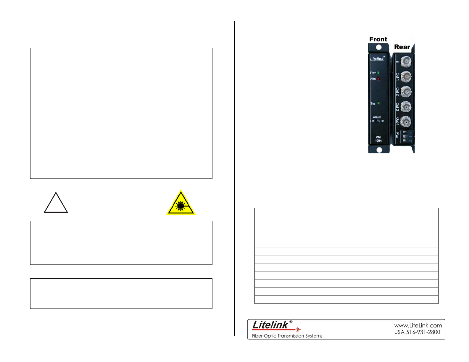
The VM-1004 is a single input, quad output wide-band video
distribution amplifier designed for those applications where a single
video source must be routed to four separate locations. Although not
a fiber optic system per se, the VM-1004 may be used with any fiber
optic transmission system where multiple video signals are required.
Technical Specifications
Video Bandwidth DC to 100 MHz
In/Out Impedance 75 ohms
In/Out Signal Level 1 volt peak to peak
Signal/Noise Ratio 75 dB minimum
Differential Gain 0.5% maximum
Differential Phase 0.5º maximum
Output Channel Isolation >40 dB
Signal Connectors BNC
Indicators Power, Signal, Alarm
Temperature Range -35º to +75ºC
Power Requirements 11-24 VAC/DC @150 mA
Physical Size (mm) 5.0”(127)L x 1.0” (25.4)W x 3.0”(7)D
All specifications measured with 1Km of 62.5u multimode fiber.
All specifications are subject to change without prior notice.
Page 2

Installation Instructions
The diagram below shows a typical installation of the VM-1004 Video
Distribution Amplifier Module. A single input signal is split and routed
to three separate isolated video outputs. Since the system is DC
coupled, all portions of the video signal are passed to the various
outputs. The VM-1004 also contains an alarm scheme that will sense
the loss of an input signal and trigger an integral ALARM indicator as
well as activate an optional ALM-1000 Alarm Sensing Module. A rear
panel switch allows this feature to be turned off if so desired.
VT-1001
Fiber Optic
Cable
Camera
Typical Fiber Optic CCTV Distribution System
Power Terminal Block Connections
Pin Function
Alarm output for use with optional Alarm Sensing Unit
1
ALM-1000. No other connections should be made to this
terminal
2 +11 to 24 DC or AC Volts input
3 AC or DC return (Common to Housing)
Be certain to check all connections, settings and voltages before
applying power
106724 Rev F
VR-1001 ALM-1000
Monitor Monitor
VM-1004
Alarm
Contacts
Monitor
Indicator Lights
Indicator Lights when
Pwr Proper power is present.
Alrm
Sig A signal is present.
The Alarm switch is used to turn the alarm function on and off.
The loss of video alarm is activated and there is
no signal present
 Loading...