

Lister Petter ALPHA LPW2, ALPHA LPWT4, ALPHA LPW4, ALPHA LPW3, NEW ALPHA LPWST4 Operator's Handbook Manual
...
1
ALPHA Series
NEW ALPHA Series
LPW/LPWS Engine
Operators' Handbook
P027-08270

2
Disclaimer
The information, specications, illustrations, instructions and statements contained within this publication
are given with Lister Petter's best intentions and are believed to be correct at the time of going to press.
Our policy is one of continued development and we reserve the right to amend any technical information
with or without prior notice. Whilst every effort is made to ensure the accuracy of the particulars contained
within this publication neither the Manufacturer, the Distributor nor the Dealer shall in any circumstances
be held liable for any inaccuracy or the consequences thereof.
The information given is subject to the Company’s current Conditions of Tender and Sale, is for the
assistance of users and is based upon results obtained from tests carried out at the place of manufacture. The
Company does not guarantee that the same results will be obtained elsewhere under different conditions.
© Copyright Lister Petter Limited, Dursley
GL11 4HS, England.
All rights reserved.
Associated Publications
Master Parts Manual ............P027-08041
Workshop Manual .................P027-08240
Technical Handbook ............ P027-08247

3
Introduction ..................................... 5
Engine Identication .............................5
Using this Handbook .............................5
Running-in ..............................................5
1. Safety Information ...................... 6
1.1 General Safety Information
Emergency Precautions
General Precautions
1.2 Personal Safety ...............................6
1.3 Precautions with Chemicals .........7
Fuel and High-Pressure Fluids ............ 7
1.4 Fuel System Precautions ...............8
1.5 Precautions with Filters
and Elements .....................................8
1.6 Precautions with Oil Seals ............9
1.7 Precautions with Batteries ............9
1.8 Precautions with Electrical
Systems ...............................................9
Wiring Cables ............................................9
Alternator ..................................................9
1.9 Waste Disposal Precautions ...... 10
1.10 Precautions before Starting ... 10
1.11 Lifting Precautions .................... 10
1.12 Precautions before Maintenance
10
2. Technical Data .......................... 11
2.1 Combustion Air
2.2 The Cooling System
3. Starting and Stopping .............. 12
3.1 General Information .................... 12
Start/Stop Control ..................................12
Oil Pressure Switch ................................12
Heater and Glow Plugs ..........................12
3.2 Key Start ....................................... 12
Starting LPW2, LPW3 and LPW4..... 12
Starting LPWS2, LPWS3, LPWS4 .... 13
Starting LPWT4 ......................................13
3.3 Failure to Start ............................. 13
3.4 Stopping (All Engines) ................. 13
4. Engine Fluids ............................14
Contents
5. Routine Maintenance ............... 16
5.1 Before Starting ............................. 16
5.2 Important Instructions ................ 16
5.3 Maintenance Schedule ............... 16
How to Service your Engine ...................16
After Servicing ........................................16
5.4 Drive Belt ...................................... 18
5.5 Cooling System ............................ 18
Draining the Cooling System .................18
Flushing the Cooling System ..........18
Filling the Cooling System .....................18
Coolant Capacity: Engine Block.............19
Coolant Capacity: Radiator ....................19
5.6 Lubricating Oil .............................. 19
Draining the Oil Sump ............................19
Relling the Oil Sump .............................19
Changing the Oil Filter............................20
5.7 Fuel System .................................. 20
Priming the Fuel System ........................20
Changing the Agglomerator ...................20
Changing the Fuel Filter ........................21
5.8 Air Cleaner .................................21
Light-Duty Air Cleaner ............................21
Cyclonic Air Cleaner ...............................21
5.9 Battery ........................................... 22
5.10 Long-Term Engine Storage ....... 22
Returning the Engine to Service............22
6. Troubleshooting ........................ 23
6.1 Method of Fault Diagnosis ......... 23
7. Maintenance Record ................25
Routine Maintenance......................... 25
Non Routine Maintenance ............... 33
8. Warranty .................................... 37
8.1 Standard Warranty Cover ........... 37
8.2 Extended Warranty Cover ........... 37
8.3 Conditions of Warranty ............... 37
8.4 Limitations of Warranty .............. 38
8.5 Purchase and Registration Details
of your Engine .................................. 38
8.6 Repairs under Warranty ............. 38
8.7 Contacting Lister Petter .............. 38
Index ..............................................39

4
2.1 Features of the LPW series diesel engines.
Oil Filter
Oil Filter
Adaptor
Fuel
Filter
Turbocharger
Lifting Eye
Radiator
Fan
LPW(S)T4
Radiator Fan
(may have 6 blades)
Alternator
Flywheel
Inlet Manifold
Starter Motor
Exhaust
Manifold
LPW3
Exhaust Manifold
Flywheel Housing
Sump
Drain Plug
Inlet Manifold
Oil Filter
Fuel Filter
LPWS2
Glow plugs

5
Introduction
This handbook explains the operation and
routine maintenance of Lister Petter watercooled diesel engines in the ALPHA (LPW)
and NEW ALPHA (LPWS) series.
Please note that If your engine is part of
a generating set, there is a separate operators' handbook for the genset, to explain
such features as the control module.
Engine Identication
To identify which model of Lister Petter
LPW(S) diesel engine you are using refer to
the engine serial number, which is stamped
on a plate attached to the engine. It identi-
es the type and build of the engine (see
table below) to enable the correct maintenance procedures to be carried out. Here
is a sample serial number:
06 001234 LPWS3 A 402
06 .........................Year code (06 = 2006)
001234 ...............Unique engine number
LPWS3 ................................ Engine model
A ............................Anti-clockwise rotation
402 ......................................Build number
The illustrations on page 4 show features
of the different engine models. When following the instructions in this handbook
you will need to be familiar with the parts
labelled.
Using this Handbook
Operating or servicing a diesel engine is
potentially dangerous. You must not attempt it unless you have the necessary
knowledge and experience.
Read each section thoroughly and carefully, taking note of all the information and
instructions given. This is for your safety and
to ensure the correct maintenance of your
engine. For specic aspects of operation
and maintenance, use the table of contents
(page 1) or the index (page 39) to nd the
section you need. Where instructions are
numbered in sequence, they must be followed in that order. This applies in particular to maintenance and repair procedures
(sections 5 and 6).
In cases of difculty, or to obtain spare
parts, please consult your local Lister Petter
distributor or dealer.
Running-in
To assist running-in all engines are des-
patched with an initial ll lubricating oil
which must be changed after 100 hours.
Your engine does not require gradual lightload running-in. Extended light-load running
should be avoided, as this could damage
the cylinder bore and allow lubricating oil
to enter the exhaust system.
LPW Diesel Engine Models
Model Characteristic features
LPW2 Two cylinders, water-cooled, naturally aspirated, direct injection
LPW3 Three cylinders, water-cooled, naturally aspirated, direct injection
LPW4 Four cylinders, water-cooled, naturally aspirated, direct injection
LPWT4 Four cylinders, water-cooled, direct injection, turbocharged
LPWS2 Two cylinders, water-cooled, naturally aspirated, indirect injection, emission-compliant
LPWS3 Three cylinders, water-cooled, naturally aspirated, indirect injection, emission-compliant
LPWS4 Four cylinders, water-cooled, naturally aspirated, indirect injection, emission-compliant
LPWST4
Four cylinders, water-cooled, naturally aspirated, indirect injection, turbocharged,
emission-compliant

6
Read the information in this section carefully and follow all the advice given. Pay
especial attention to the cautions and
warnings demonstrated below, which are
used throughout this handbook.
CAUTION
This caution draws attention to special
information or procedures which must
be correctly observed, to avoid damage
to, or destruction of, equipment.
WARNING
This warning draws attention to special
information or procedures which must
be strictly observed. Failure to do so may
result in personal injury.
WARNING
THIS WARNING DRAWS ATTENTION TO
SPECIAL INFORMATION OR PROCEDURES WHICH MUST BE STRICTLY OBSERVED. FAILURE TO DO SO MAY RESULT
IN SERIOUS INJURY OR DEATH.
1.1 General Safety Information
Starting and operating any diesel engine is
potentially dangerous. Do not attempt to do
so unless you have the necessary knowledge and experience. Ensure that anyone
attempting to start and operate your diesel
engine has been propertly trained and instructed in the correct procedures.
CAUTION
Follow all safety instructions accurately.
Carefully read and follow all safety information and instructions in this manual.
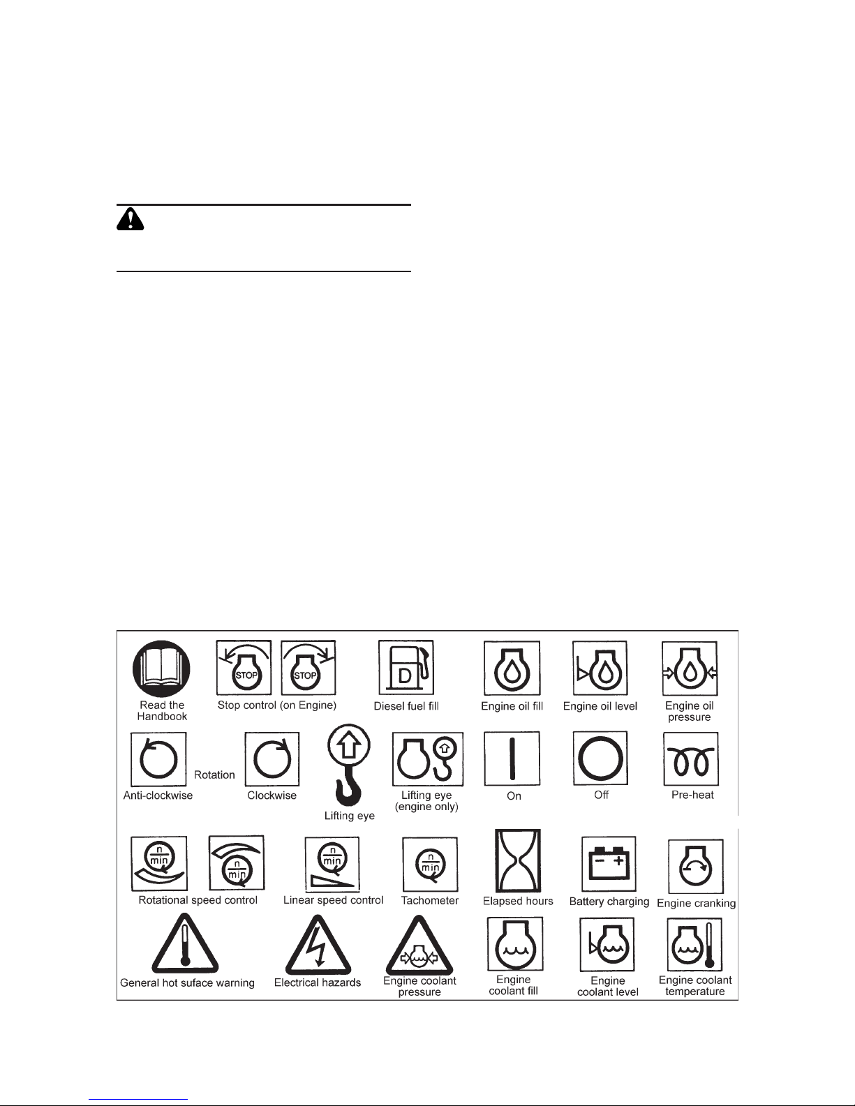
Observe the safety and informative sym-
bols on your engine and equipment.
Emergency Precautions
• Be prepared with suitable equipment
and knowledge in case a re starts.
• Identify a location from which calls to
the emergency services can be made if
necessary.
• Ensure a third party knows where you are
working and when you leave the working
area.
General Precautions
• Ensure the engine is securely mounted.
• Ensure that there is a generous supply of
cooling and combustion air available.
• Keep the engine and surrounding area
clean.
• Some accessories may require guards
which must be supplied and tted by
the purchaser. Keep all safety guards in
position.
• Do not make any unauthorised modications as these may affect the safe operation of the engine and put the operator
at risk.
1.2 Personal Safety
• Wear personal protective clothing and
safety equipment appropriate to the
work being done.
• Keep clear of moving parts at all times.
WARNING
KEEP THE BODY AND CLOTHING CLEAR
OF MOVING OR HOT PARTS AT ALL TIMES.
CONTACT OF MOVING PARTS WITH UNPROTECTED SKIN CAN CAUSE SEVERE
BURNS. ENTANGLEMENT WITH ROTATING
EQUIPMENT CAN CAUSE SERIOUS INJURY
OR DEATH.
• Tie long hair back securely.
• Wear close-tting clothing.
• Do not wear a necktie, scarf, loose cloth-
ing or necklace when working close to a
running engine.
1. Safety Information
7
1. Safety Symbols This gure identies the ISO 8999 symbols currently used by Lister Petter.
• Where possible, remove rings and other
jewellery to prevent entanglement in
moving parts. These items could also
cause a short circuit if any part of the
electrical system is being worked on.
WARNING
Prolonged exposure to loud noise can
cause impairment, or loss, of hearing.
• Wear suitable ear protection against
objectionable or uncomfortable loud
noise.
• To avoid loss of concentration, do not
use music or radio headphones while
operating an engine.
• When undertaking maintenance, do not
work under any plant that is only held by
overhead lifting equipment.
• Where appropriate, make sure that
guards are properly tted.
1.3 Precautions with Chemicals
Protect yourself from exposure to hazardous chemicals at all times, as this can
cause serious injury. Potentially hazardous
chemicals include lubricants, fuel, coolant concentrate, battery acid, paint and
adhesives.
Manufacturers' safety data sheets will
provide specic details of the physical and
health hazards, safety and emergency
procedures and any necessary personal
protection equipment required while working with hazardous materials.
• Handle uids with care at all times.
• Rectify any fuel, coolant or oil leak as
soon as is practicable and clean up any
spillages when they occur.
• Remove any build-up of grease, oil or
debris.
• If any fluid other than lubricating oil
comes into contact with the skin, clean
off immediately. In the case of lubricating
oil, clean off as soon as is practicable.
Fuel and High-Pressure Fluids
• Store fuel and other ammable liquids
away from re hazards.
• Always stop the engine before refuel-
ling.
1. Safety Information

8
• Do not overll the fuel tank.
• When working with fuel do not smoke or
work near to heaters or other re haz-
ards.
• High-pressure uids are extremely hazardous. Never allow any part of the body
to come into contact with high-pressure
fuel oil, compressed air or hydraulic oil,
for example when testing fuel injection
equipment.
WARNING
Do not expose pressurised containers to
heat, and do not incinerate or puncture
them.
WARNING
NEVER TOUCH OR INGEST HIGH-PRESSURE FLUIDS SUCH AS HYDRAULIC OIL,
COMPRESSED AIR OR FUEL OIL. THIS
COULD LEAD TO SERIOUS INJURY, OR
DEATH.
1.4 Fuel System Precautions
WARNING
NEVER ALLOW ANY UNPROTECTED SKIN
TO COME INTO CONTACT WITH THE INJECTOR SPRAY AS FUEL MAY ENTER THE
BLOODSTREAM WITH FATAL RESULTS.
WARNING
Never make unauthorised adjustments
to the emission-compliant fuel injection
pumps. This could be dangerous and
invalidates warranty claims. In the USA
unauthorised adjustment of emission
critical components is prohibited by Federal Law, incurring civil penalty.
• When priming or checking the fuel injection pump timing, care must be taken to
wipe any spilled fuel from the outside of
the engine.
• Always t a new joint when a union has
been disturbed.
• Special care must be taken to see that
there is no leakage from the joints of the
fuel pipe connection to the pump.
• When tightening or loosening fuel injection pump delivery connections use two
spanners to prevent un-sealing of fuel
pump delivery valve holders.
• When refitting the fuel pipe from the
pump to the injector, the connection to
the injector must be tightened before
the connection to the fuel pump. This
procedure will ensure that there is no
leakage from these joints.
• It is most important that all fuel joints are
tight and leak proof.
• Always ll the fuel tank through a ne
strainer. It is best to do this at the end of
the engine work period so that any sediment stirred up has time to settle before
the engine is used again, and the risk of
condensation contaminating the fuel is
minimised. If using a can, avoid tipping
out the last few drops.
• Funnels are very difcult to keep clean
in dusty conditions. Wash them before
and after use and wrap them up when
not required, or ll the tank direct from
a small-mouthed screw-capped can.
• The fuel injection equipment is manufactured to very accurate limits and the
smallest particle of dirt will destroy its
efciency.
CAUTION
Keep the fuel free from water and contaminants.
1.5 Precautions with Filters
and Elements
• Used lters and elements contain some
of the ltered liquid and should be han-
dled and disposed of with care.
• After handling new or used elements,
wash your hands thoroughly.
WARNING
Do not allow fuel or new or used lubricating oil to come into contact with unprotected skin. It is dangerous and could
cause skin irritation.
1. Safety Information

9
1. Safety Information
WARNING
Take careful precautions with lters and
elements. The materials used in the manufacture and treatment of some types may
cause irritation or discomfort if they come
into contact with the eyes or mouth, and
they may give off toxic gases if burnt.
1.6 Precautions with Oil Seals
Some engines may be tted with seals or
'O' rings manufactured from Viton or a similar material. When these substances are
exposed to abnormally high temperatures,
in excess of 400°C (752°F), an extremely
corrosive acid is produced.
WARNING
IF AN OIL SEAL CONTAINING VITON (OR
SIMILAR MATERIAL) DEGENERATES, IT
PRODUCES AN EXTREMELY CORROSIVE
ACID THAT CANNOT BE REMOVED FROM
THE SKIN. IF YOU SEE SIGNS OF DECOMPOSITION, OR ARE IN DOUBT, WEAR
DISPOSABLE HEAVY-DUTY GLOVES.
• If in any doubt about an oil seal, always
wear disposable heavy-duty gloves.
1.7 Precautions with Batteries
Batteries contain hazardous sulphuric acid.
Great care therefore needs to be taken
when using them.
• Do not smoke near batteries and keep
sparks and ames away from them. Do
not work near to heaters or other re
hazards.
• Switch off the battery charger before
connecting or disconnecting the charger
leads. Disconnect the battery negative
(earth) lead rst and reconnect last.
• Keep the top of the battery well venti-
lated during charging.
• Never 'ash' connections.
• Never use a damaged battery.
• Do not attempt to charge a frozen bat-
tery; it may explode. Instead, warm the
battery to 16°C (60°F).
WARNING
Take especial care with batteries, which
contain highly corrosive sulphuric acid
which is poisonous, will burn skin and
clothing, and will cause permanent damage including blindness if splashed into
the eyes. If acid accidentally comes into
contact with skin, eyes or clothes, ush it
away with copious amounts of fresh water
and seek medical aid.
1.8 Precautions with Electrical
Systems
• Ensure that the battery is of sufcient
capacity to start the engine down to its
minimum operating temperature, taking into account any drag that may be
imposed on the engine by the type of
trans mission that is attached to it.
• Ensure that the battery and all engine
wiring cables are of sufcient size to
carry the currents required.
• Check that the engine-mounted alternator is of sufcient output to cope with
the total electrical load required by the
machine to which it is tted.
Wiring Cables
Ensure that the engine wiring cables are:
• Bound together in a loom and adequately
supported.
• Routed to avoid any hot surfaces, particularly the exhaust system.
• Not in contact with any rough surfaces
or sharp corners so as to avoid any pos-
sibility of chang taking place.
Alternator
The following points must be strictly observed when an alternator is tted, otherwise serious damage can be done.
• Never connect a battery into the system
without checking that the voltage and
polarity are correct.
• Never remove any electrical cable while
the battery is connected in the circuit.
• Never disconnect the battery unless the
10
engine has stopped and all switches are
in the off position.
• Always ensure that cables are tted to
their correct terminals.
CAUTION
A short circuit or reversal of polarity will
ruin diodes and transistors.
• Never 'ash' any connection to check the
current ow.
• Never experiment with any adjustments
or repairs to the system.
• Always disconnect the battery and alternator before commencing any electric
welding when a pole strap is directly or
indirectly connected to engine.
1.9 Waste Disposal Precautions
• Extreme care must be taken to ensure
that waste oil, fuel, lter elements, cool-
ant concentrate, battery electrolyte, solvents or other toxic wastes are disposed
of in accordance with local regulations to
prevent contamination.
WARNING
To avoid contamination and personal
injury, never dispose of toxic or other
waste except in accordance with ofcial
regulations.
1.10 Precautions before Starting
WARNING
Starting any diesel engine can be dangerous in the hands of inexperienced people.
Engine operators must be instructed in
the correct procedures before attempting
to start any engine.
• Ensure that the engine is free to turn
without obstruction.
• Check that the lubricating oil level is
correct. The oil sump must be lled to
the ‘full’ mark on the dipstick; do not
overll.
• Check that the radiator is lled to within
13-25 mm (0.5-1.0 in) below the neck of
the radiator ller.
• Check that the fuel supply is adequate
and the system is primed.
• Ensure that the battery is connected,
fully charged and serviceable.
• Where possible, disengage the driven
equipment while starting.
1.11 Lifting Precautions
Engine lifting eyes are tted to ALPHA and
NEW ALPHA engines. The following points
must be considered before attempting to
lift the engine.
• Ensure any lifting equipment to be used
has the correct capacity to lift the engine.
• Ensure that the lifting equipment is designed to give a vertical lift from directly
above the engine lifting eye.
• Check that the engine lifting eyes are not
damaged and that they are secure.
• The engine lifting eyes are suitable for
lifting the engine and accessory assem-
blies originally tted by Lister Petter.
WARNING
Engine lifting eyes must not be used to lift
the complete plant.
WARNING
DO NOT WORK UNDER ANY PLANT THAT
IS ONLY HELD BY OVERHEAD LIFTING
EQUIPMENT.
1.12 Precautions before
Maintenance
• Understand the service procedures before commencing any work.
• Ensure all starting devices are removed
or isolated before beginning any work on
engine or plant.
• Ensure the work area is clean, dry, well
ventilated and has adequate lighting.
• Ensure that all persons using equipment
or processes in connection with the
maintenance of plant and mach inery
have received adequate and suitable
training.
1. Safety Information

11
2. Technical data for Lister Petter LPW and LPWS engines.
Table 2 gives technical data for all the engines in the Lister Petter ALPHA (LPW) and
NEW ALPHA (LPWS) range.
2.1 Combustion Air
Engine performance is affected by ambient temperature, which is taken to mean
the temperature of the air entering the
engine.
The temperature of the combustion air is
measured at the air inlet manifold, or the air
cleaner, and the temperature of the cooling
air is measured at the radiator fan inlet. The
higher of these two temperatures is taken
as being ambient temperature as far as
engine ratings are concerned.
Every effort should be taken to ensure
that the air cleaner draws in combustion
air at a consistent ambient temperature.
2. Technical Data
Lister Petter LPW, LPWT, LPWS and LPWST
engines are able to run satisfactorily at
ambient temperatures up to the standard
engine reference condition of 25°C (77°F)
without derating. If the combustion air temperature rises above this temperature, the
rated power must be reduced in accordance
with the relevant standard:
LPW/LPWT ........................... ISO 3046
LPWS ................................... ISO 14396
Generating Sets ................... ISO 8528
The maximum permitted ambient temperature is 52°C (125°F).
2.2 The Cooling System
Cooling is by a radiator with water circulation being assisted by an engine mounted,
centrifugal, belt driven water pump using
a single belt.
Technical Data
LPW series model LPW2, LPW3, LPW4 LPW(S)T4 LPWS2, LPWS3, LPWS4
Rotation Anticlockwise (when looking on the ywheel)
Type of injection Direct Indirect
Firing order:
2 cylinders 1 - 2 n/a 1 - 2
3 cylinders 1 - 2 - 3 n/a 1 - 2 - 3
4 cylinders 1 - 3 - 4 - 2 1 - 3 - 4 - 2 1 - 3 - 4 - 2
Electrical system 12v negative earth
Starter battery charging 12v engine-mounted alternator
Oil pressure
at idle 1.0 bar (14.5 lbf in2)
3000
r/min
1
2.0 bar
(29.0 lbf in2)
2.5 bar
(36.3 lbf in2)
2.0 bar
(29.0 lbf in2)
Oil sump capacity Refer to table 5.6.3a: Sump Capacity (page 19).
Coolant capacity Refer to table 5.5: Engine Block Coolant Capacity (page 18).
Note: 1. Oil Pressure at 3000 r/min is with the oil at 110 oC (230 oF).

12
The following information is of a general
nature and should be read in conjunction
with the manufacturers' instructions for any
other equipment you are using.
WARNING
Do not attempt to start or operate a diesel engine unless you have been properly
trained. Read the safety information in
section 1 and the information below on
controls and the starting procedures.
CAUTION
DO NOT USE ETHER-BASED COLD-START
AIDS UNDER ANY CIRCUMSTANCES.
WARNING
DO NOT BREATHE EXHAUST GASES. THEY
CONTAIN CARBON MONOXIDE, A COLOURLESS, ODOURLESS GAS THAT CAN CAUSE
UNCONSCIOUSNESS AND DEATH.
CAUTION
On LPWT4 engines, ensure that the turbocharger housing is full of oil. Failure to
do so can result in serious damage to the
bearing. Run on 'no load' after starting
for 30 seconds, to ensure an adequate
oil supply to the turbocharger, and for 30
seconds before stopping to allow the heat
from the bearing to dissipate.
3.1 General Information
Start/Stop Control
The basic engine has a plastic knob tted
to the control. Other variants for automatic
or remote operation are available.
Engines not tted with a fuel control sole-
noid have a spring clip to hold the engine
control in the stop position.
WARNING
Use suitable hand protection when stopping the engine, as the stop control may
be hot after prolonged running.
3. Starting and Stopping
Oil Pressure Switch
If an oil-pressure switch bypass button is
tted it must be depressed during engine
cranking, and until the engine attains full
speed.
Heater and Glow Plugs
LPW: a 345 W heater plug (A) may be tted
to the inlet manifold.
LPWT4: a 696 W heater plug (A) is tted in
the inlet manifold.
LPWS: a 12v glow plug (B) is tted in each
cylinder and a 696 W heater plug (A) is also
tted in the inlet manifold as standard.
3.1 Heater and glow plugs. A: Manifold heater plug.
B: Cylinder glow plug.
3.2 Key Start
Before starting your engine read the cautions, warnings and the general information
above.
Starting LPW2, LPW3 and LPW4
1. With reference to gure 3.2.1, move the
engine control lever (A) clockwise until it
is against the stop screw (B).
2. On variable speed engines move the
speed control to the fast position.
3. Turn the key clockwise to the start position. Immediately the engine starts the
key must be turned anticlockwise to the
run position.
3.2.1 Start control.

13
3. Starting and Stopping
4. On variable speed engines reduce the
engine speed as necessary.
Starting LPWS2, LPWS3, LPWS4
1. With reference to gure 3.2.1, move the
engine control lever (A) clockwise until it
is against the stop screw (B).
2. On variable speed engines move the
speed control to the fast position.
3. For ambient starting temperatures above
-10°C (14°F) turn the key clockwise and
hold it in the preheat position for 5 to
10 seconds before turning it to the start
position.
For ambient starting temperatures below
-10°C (14°F) turn the key clockwise to
the preheat position for 15 to 20 seconds before turning the key to the start
position.
Immediately the engine starts the key
must be turned anticlockwise to the run
position.
4. On variable speed engines reduce the
engine speed as necessary.
Starting LPWT4
1. With reference to gure 3.2.1, move the
engine control lever (A) clockwise until it
is against the stop screw (B).
2. On variable speed engines move the
speed control to the fast position.
3. For ambient starting temperatures above
-10°C (14°F) turn the key clockwise and
hold it in the preheat position for 10 to
15 seconds before turning it to the start
position.
For ambient starting temperatures below
-10°C (14°F) turn the key clockwise to
the preheat position for 15 to 20 sec-
3.2.2 Key start.
onds before turning the key to the start
position.
Immediately the engine starts the key
must be turned anticlockwise and held
in the preheat position until the engine
has attained full speed.
4. When the engine has attained full speed
turn the key anticlockwise to the run
position.
5. On variable speed engines reduce the
engine speed as necessary.
3.3 Failure to Start
Should the engine fail to start within 30
seconds, release the key and, after allowing
sufcient time for all moving parts to stop,
attempt to restart.
3.4 Stopping (All Engines)
CAUTION
It is recommended that LPWT4 engines
run on 'no load' for 30 seconds before
stopping to allow the heat from the turbocharger bearing to dissipate.
1. If possible, remove the load from the
engine.
2. If a variable speed control is tted reduce
the engine speed.
3. On engines tted with a fuel control solenoid turn the key to the off position.
On engines not tted with a fuel control
solenoid move the engine control lever
anticlockwise into the stop position
(gure 3.4) and turn the key to the off
position.
CAUTION
Turning the key to the off position alone
will not stop the engine unless a fuel
control solenoid is tted.
3.4 Stop control.

14
4.1 Fuel Specication
The engine must be used only with diesel
fuel oil that conforms to one of the following:
• BS 2869:1988 Class A2;
• BS EN590:1995 Class A1;
• USA Specifi cation ASTM D-975-77
Grades 1-D and 2-D;
• BSMA 100 Class M1 for marine use.
The fuel must be a distillate and not a
residual oil or blend.
Vaporising oils are not suitable as fuels
for Lister Petter engines.
4.1.1 LPWS Bio
LPWS Bio is a specially developed engine
range that will run on B100 (100% biofuel)
as well as on those fuels specied above.
CAUTION
Although the engines may operate on
fuels outside the above specications,
such operation may result in excessive
wear and damage.
CAUTION
It is of the utmost importance to keep fuel
free from water and other contaminants.
The fuel injection equipment is manufactured to very accurate limits, and the
smallest particle of dirt will destroy its
efciency.
4.2 Oil Specication
To assist running-in, all engines are des-
patched with an initial ll lubricating oil
which must be changed, with the lter, after
the rst 100 hours.
All subsequent oil changes must be as
specied in 5. Routine Maintenance.
• The temperatures cited in gure 4.3 are
the ambient temperatures at the time
when the engine is started (see 2.2
Combustion Air). If monograde oils are
used and running ambient temperatures
are signicantly higher than starting temperatures, a higher viscosity oil should
be selected, subject to satisfactory starting performance. Multi grade oils may be
used to overcome the problem.
• Where ambient temperatures are variable and it is not practical to continually
change oils accordingly, a suitable multigrade oil is recommended to ensure
adequate starting performance at the
lowest temperature likely to be encountered.
• The engines must be run on heavy-duty
lubricating oils. Straight mineral oils
are not suitable, neither are oils of less
detergency than specied.
• API CF-4, API CG-4, API CH or API CI oils
must be used in all engines.
• For engines in long-running installations
Lister Petter should be consulted.
Oil Viscosity
Figure 4.3 shows the recommended oil
viscosity ranges for various °C ambient
temperatures from cold start to maximum
running.
Non-synthetic oils at very low tempera-
tures will suffer from wax crystallisation, so
synthetic oils are recommended for these
conditions.
SAE 5W-20 oils are recommended on
the basis that they are fully synthetic and
are technically suitable for use up to 25°C
(77°F). (Monograde SAE 5W is not normally available as a synthetic oil therefore
does not appear in the chart.)
SAE 30 and 10W-30 oils may be used at
up to 52°C (126°F), but oil consumption
may be affected. 10W-40, 15W-40 and
20W-40 multi grades are recommended
for continuous full-load operation at this
temperature. (Monograde SAE 40 oils are
not recommended.)
4. Engine Fluids

15
4. Engine Fluids
4.2 Recommended oil viscosity grades for different temperature ranges.
Note A: intermittent running; note B; synthetic oils only. NB. The formula for conversion from degrees
Fahrenheit to degrees Centigrade is°F = (1.8 x °C) + 32.
In order to maintain the cold-starting
characteristics of any recommended grade
it is essential that oil changes are made
within the Lister Petter recommendations
(see 5. Routine Maintenance).
An oil change is recommended immediately if the engine fails to reach its normal
cold-start cranking speed owing to excessive oil viscosity.
CAUTION
Dilution of the lubricating oil with fuel
will adversely affect cold starting and will
increase oil consumption.
4.3 Coolant* Mixture Concentration
To determine the amount of coolant con-
centrate to be added, rst calculate the
total coolant capacity by adding together
the engine and radiator volumes (see 5.5.4
Coolant Capacity).
A 50% concentration of coolant additives
by volume must be maintained under all
operating conditions. If a component fails
due to an incorrect coolant concentration
being used it will not be covered by the LP
warranty.
When topping up coolant please ensure
that the “top up” is of the correct concentrate mix and not just water.
The specication of the coolant concentrate should comply with one of the
following:
BS6580 : 1985;
MIL-A-11755D;
MIL-A-46153/B.
* Coolant dened as the combination of water,
corrosion inhibitor and antifreeze.

16
5.2 Important Instructions
• Remove the battery before carrying out
any maintenance work on an engine.
• Disconnect the battery and alternator
before commencing any electric welding
when a pole strap is directly or indirectly
connected to the engine.
• Fuel pumps and injectors can only be
checked and set off the engine using
suitable specialist test equipment.
5.3 Maintenance Schedule
The table on page 17 sets out the frequency
with which maintenance and servicing
tasks should be performed. This is the
minimum frequency required to keep your
engine running at peak performance with
trouble-free operation.
The instructions are based on average
operating conditions. Air cleaners, lubri-
cating oil and fuel lters will require more
frequent attention if conditions are very
dusty. Decarbonising may be required more
often if the engine has been running on light
loads for long periods.
How to Service your Engine
Instructions are given in the remaining sections of this chapter.
After Servicing
• It is essential to ensure that nuts and
bolts are tightened to the torques speci-
ed in the Workshop Manual.
• When re-assembling an engine lubricate
all moving parts with engine oil.
• Renew nuts and bolts that have been
taken from high-stress locations. In
particular nuts and/or bolts from the
connecting rods should be renewed.
CAUTION
Long periods of light or ‘no load’ running
early in the engine’s life may lead to
cylinder bore glazing and high oil con-
sumption.
5. Routine Maintenance
This section is designed primarily for use
by trained technicians but it does contain
sufcient information, illustrations and detail to allow the operator to perform basic
maintenance work.
WARNING
Routine maintenance must be performed
by qualied personnel who are conversant
with the hazards of oil, fuel, electricity
and machinery.
This work can be carried out only if the
necessary hand and service tools are avail-
able. When the user has insufcient tools,
experience or ability to carry out adjustments, maintenance and repairs this work
should not be attempted.
Where accurate measurements or torque
values are required they can only be made
using calibrated instruments.
CAUTION
Under no circumstances should makeshift
tools or equipment be used, as their use
may adversely affect safe working procedures and engine operation.
These recommendations and instructions cover several engine models, therefore they are of a general nature.
The engine may include optional equip-
ment not specically covered in this book.
5.1 Before Starting
Before starting any dismantling procedure
read 1. Safety Information and Pre cau tions.
Consider the following:
• Do you know and understand the engine
and all the related systems?
• Do you have sufficient electrical and
mechanical knowledge and skills to
understand the symptoms?
• Do you have suitable electrical diagnos-
tic equipment available?
• Do you have, or have access to, the nec-
essary Lister Petter spare parts?

17
1. See also Table 1 above. 2. Inspect more frequently if fuel is contaminated. Inspect regularly on engines
in low-duty cycle applications, for example, stand-by generating sets.
5. Routine Maintenance
Maintenance Schedule
At all times
Continuously monitor engine performance.
Observe the correct oil and lter change periods
as specied below.
1. Oil and Filter Change Periods (hrs=hours)
Ambient
temperature
LPWS(T) LPWT LPW
Every: Every: Every:
Above 35°C
(95°F)
125 hrs 125 hrs 250 hrs
Up to 35°C
(95°F)
250 hrs 250 hrs 500 hrs
Every Day
Check the level and condition of lubricating oil.
Check the coolant level.
Check the level and supply of fuel.
Examine the cooling fan for damage.
Clean the air cleaner if the engine is operating
under very dusty conditions.
After the rst 100 hours
Marine propulsion engines: check idling speed
and reset if necessary.
Change the initial ll lubricating oil1.
Renew the oil lter.
Every 125 hours
1
Do all the above, and the following:
Clean the air cleaner if the engine is operating
under moderately dusty conditions.
Check for fuel, coolant and oil leaks.
Check the serviceability of the battery.
Every 250 hours
1
Do all the above, and the following:
Check the condition and tension of the radiator
drive belt.
Check the radiator ns for contamination or
blockage.
Clean the fuel injector nozzles if exhaust is dirty.
Renew the fuel lter element if the fuel is not
perfectly clean.
Every 500 hours
Do all the above, and the following:
Renew the fuel lter element.
Renew the air cleaner element.
Check the air induction systems for leaks,
damage and restrictions.
Change the lubricating oil1.
Renew the oil lter1.
LPWT4: Clean the crankcase breather canister
and hoses.
Every 1000 hours
Do all the above, and the following:
Check all external nuts, bolts and unions for
tightness.
Ensure that all guards are rmly attached and
are not damaged.
Replace the fuel-lift pump diaphragm.
2
Every 2000 hours
Do all the above, and the following:
Drain and clean the engine-mounted fuel tank,
if tted.
Check the engine and speed controls for free
movement.
Clean and check, and if necessary replace, the
fuel injector nozzles.
Check the radiator ns and radiator fan blades
for damage.
Replace the radiator fan drive belt, irrespective
of its condition.
Check the lubricating oil pressure.
Renew the air cleaner element.
Every year
Drain, ush and rell the cooling system,
adding new coolant concentrate to a 40%
concentration.
Drain and replace the lubricating oil and lter,
irrespective of their condition, if the engine
has run for less than 250 hours in the
preceding twelve months.
On marine engines, change the air cleaner
element.if it was not changed at the
prescribed intervals.
Every two years
Replace the coolant hoses, irrespective of their
condition.
When necessary
Undertake a decake/major overhaul.
18
5. Routine Maintenance
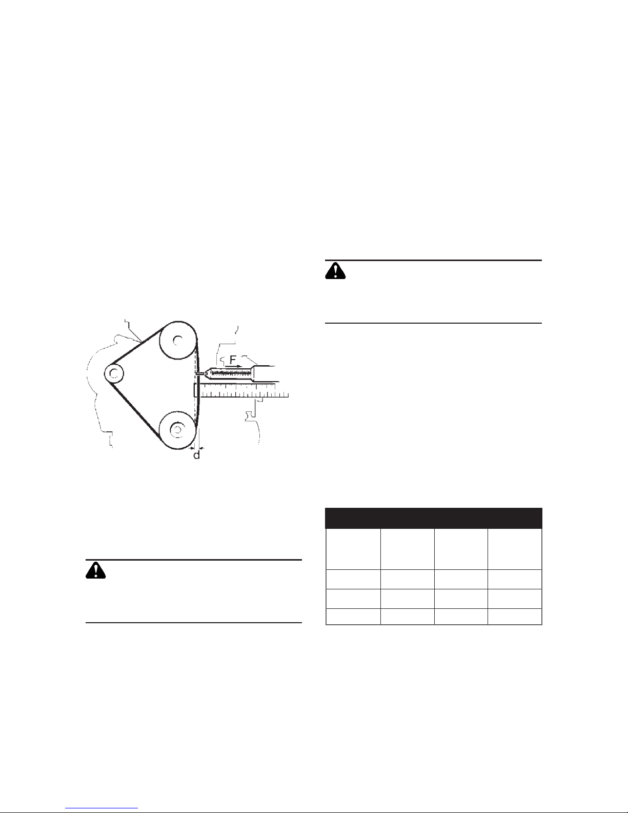
5.4 Checking drive-belt tension. F denotes force
and d dentoes distance.
5.4 Drive Belt
The tension of the drive belt (see gure 5.4)
must be checked:
1. After the rst 50 hours;
2. Every 250 hours;
3. After an overhaul when the belt is retted
or replaced.
4. The drive belt must be replaced every
2000 hours, irrespective of its condition.
When a new belt is correctly tted and tensioned, a force (F) of 31.0 —33.5 N (7.0—7.5
lbf) is required to deect it a distance (d) of
3.5mm (0.14in).
On subsequent checking and adjustment
a force (F) of 22.0-24.0N (5.0-5.4lbf) is
required to deect it a distance (d) of 3.5
mm (0.14 in).
Flushing the Cooling System
1. With the bottom hose removed, ush
the radiator through the ller with clean
fresh water, preferably using a hose pipe,
until clean water emerges.
2. With the top and bottom hoses re-
moved from the engine, ush the engine
through the top hose with clean fresh
water, preferably using a hose pipe, until
clean water emerges.
3. Replace the hoses.
Filling the Cooling System
CAUTION
Under some circumstances an air lock can
occur when lling the system, causing a
false level indication.
1. Ensure the hoses have been replaced.
2. Rell the system with clean fresh water
and coolant concentrate to a 40% concentration while bleeding air from the
system at a suitable point. The radiator
should be lled to within 13.0 —25.0
mm (0.5—1.0 in) below the neck of the
radiator ller.
3. Run the engine for a short time and
check the coolant level.
Coolant Capacity: Engine Block
Table 5.5.
Engine Block Coolant Capacity
LPW2
LPWS2
LPW3
LPWS3
LPW4
LPWT4
LPWS(T)4
litres 2.1 2.5 3.0
pints 3.7 4.4 5.3
US gallons 0.55 0.66 0.79
Coolant Capacity: Radiator
There are a number of radiator options
available for LPW, LPWT and LPWS engines,
including some which may not have been
originally tted by Lister Petter.
For these reasons it is advisable to
ascertain the radiator capacity which must
5.5 Cooling System
Draining the Cooling System
WARNING
The cooling system is pressurised and extreme care must be taken when removing
the radiator cap if the engine is hot.
1. Place a suitable container under the
radiator bottom hose if the coolant is to
be retained.
2. Slacken the clips of the hose and slide
the hose off.
3. Remove the radiator ller cap.
4. Allow sufcient time for the system to
drain.

19
Draining the Oil Sump
Before draining the oil read 1.5 Precautions
with Filters and Elements and 1.6 Precautions with Oil Seals.
The oil sump drain plugs are located on
the oil lter side and the gear end of the
crankcase. It is better if the engine has
been run immediately before draining, as
the warm oil will drain more quickly.
1. Remove the oil ller cap.
2. Remove the drain plug and allow the oil
to run into a suitable retainer.
3. Clean the drain plug threads and coat
them with Hylomar PL32/M, Loctite 572
or Hylogrip 760.
4. Replace the plug and tighten it.
Relling the Oil Sump
Table 5.6.3a gives the sump capacity
(excluding the lter) of all engines in the
LPW range.
Sump Capacity
(Figures exclude the lter)
LPW2
LPWS2
LPW3
LPWS3
LPW4
LPWT4
LPWS(T)4
All builds except 28, 51, 52, 57, 58, 59
litres 3.00 3.75 5.50
pints 5.28 6.60 9.68
US gallons 0.79 0.99 1.45
Builds 28, 51, 52, 57, 58, 59
litres 5.85 8.25 11.5
pints 10.29 14.52 20.23
US gallons 1.55 2.18 3.03
Table 5.6.3.
5. Routine Maintenance
then be added to that given in the table
above under Engine Block before determin-
ing the amount of coolant concentrate to be
added to maintain a 40% concentration.
The capacity of hoses on remote radiator applications must also be taken into
consideration.
5.6 Lubricating Oil
Check the lubricating oil daily using the
dipstick, and top up when necessary with
oil of the correct type and specication (see
section 4.2 Oil Specication). Table 5.6.3b
gives the capacity between the dipstick
marks of all engines in the LPW range.
Capacity Between Dipstick Marks
LPW2
LPWS2
LPW3
LPWS3
LPW4
LPWT4
LPWS(T)4
All builds except 28, 51, 52, 57, 58, 59
litres 0.90 0.95 1.20
pints 1.58 1.67 2.11
US gallons 0.24 0.25 0.32
Builds 28, 51, 52, 57, 58, 59
litres 1.50 1.75 2.20
pints 2.64 3.08 3,87
US gallons 0.39 0.46 0.58
Table 5.6.1.
Change the lubricating oil and filter for
the rst time at 100 hours and then as
specied in 5.3. Maintenance Schedule
(table 1).
CAUTION
Continuous operation under heavy loads
in ambient temperatures above 35°C
(95°F) causes the oil to deteriorate more
quickly.

20
5. Routine Maintenance
3. Screw the new lter onto the crankcase
lter adaptor, or lter mounting bracket
facing, until the rubber joint just makes
contact with the crankcase facing of
mounting bracket.
4. Screw the lter on a further quarter to
half a turn.
5. Start the engine and run it for a few
minutes to circulate the oil.
6. Stop the engine and allow time for the oil
to drain down and check the level on the
dipstick.
7. Add more oil if necessary.
5.7 Fuel System
Priming the Fuel System
1. Ensure there is sufcient fuel.
2. Figure 5.7.1 shows the two types of lter.
Release the bleed screws (A) on the lter
and re-tighten when no further air bubbles are expelled.
3. On variable speed engines move the
speed control to the fast position.
4. Move the engine stop/run control from
the stop to the run position (gure 3.3.2,
page 13).
5. Operate the fuel-lift pump by hand.
1. Ensure the new oil meets the correct
specication and viscosity, as given in
4.2 Oil Specication.
2. Fill the sump through the oil ller (A) to
the upper mark on the dipstick.
3. Start the engine and run it for a few
minutes to circulate the oil.
4. Stop the engine and allow time for the
oil to drain down. Check the level on the
dipstick.
5. Add more oil if necessary.
CAUTION
Do not overll with oil. If a cylinder-head
oil filler is fitted the oil must only be
poured into the ller at a rate which enables it to drain into the crankcase. If the
oil is poured in too quickly it can ood the
crankcase breather holes and escape into
the inlet manifold and cylinders.
Changing the Oil Filter
The full-ow lter is a spin-on cartridge type
located on the crankcase door.
Only approved lters should be used,
as these have high-temperature-resistant
joints, adequate lter paper characteristics
and a rigid case. Other lters may have the
same external dimensions and thread as
the genuine one but may fail in service.
Before changing the lter read 1.5 Pre-
cautions with Filters and Elements.
1. Use a band-type gripping tool to remove
the lter from the engine.
2. Lightly grease or oil the face of the rub-
ber joint on the new lter.
5.6.1 The oil ller (A) and dipstick handle.
Changing the Agglomerator
Before starting, read 1.5 Precautions with
Filters and Elements and study figure
5.7.2.
1. Before removing the agglomerator cartridge (A) from the agglomerator head
(B) you should rst drain the water from
the agglomer ator by unscrewing the
drain tap (C).
2. Using a suitable strap wrench, unscrew
the cartridge (A) from the head (B).
5.7.1 Priming the fuel lter: the bleed screws are
denoted by A.

21
3. Screw a new cartridge onto the head and
hand-tighten it.
Changing the Fuel Filter
The element should be renewed every 500
hours, or more frequently if for any reason
the fuel is known to be dirty.
Before changing the lter read 1.5 Pre-
cautions with Filters and Elements.
1. Isolate the fuel supply or drain the
tank.
2. Unscrew the centre bolt (A) of the lter
assembly.
3. Discard the old element (B) and t a
replacement.
4. Fill the fuel tank and prime the system
(see 5.7.1 Priming the Fuel System).
5. Run the engine and check to see that no
fuel is leaking from the lter.
ture above the standard engine reference
condition of 25°C (77°F) will incur an
engine derate factor.
Light-Duty Air Cleaner
The snout is normally tted lying horizontally and pointing towards the gear end,
although the cleaner itself can be rotated
through 360°.
1. Release the three cover clips (A).
2. Lift off the cover (B).
3. Lift out the element (C).
4. Fit a new element.
5. Replace the cover and clips.
5. Routine Maintenance
5.7.2. The agglomerator:
cartridge (A); head (B);
drain tap (C).
5.7.3 Changing the fuel lter. The centre bolt is
denoted by A and the old element by B.
5.8.1 The light-duty air cleaner.
5.8.2 The cyclonic
air cleaner.
5.8 Air Cleaner
Every effort should be taken to ensure that
the air cleaner draws in combustion air at
the prevailing ambient temperature.
Any increase in combustion air tempera-
Cyclonic Air Cleaner
A cyclonic air cleaner can be remote or
engine-mounted over the ywheel housing. In either case it is connected to the
engine by a moulded rubber hose secured
by jubilee clips.
1. Regularly remove the dust cap (A) and
empty out all the dust.
2. Gain access to the paper element by
undoing the two over-centre clips (B).
3. Remove the element.

22
5. Routine Maintenance
4. Clean the element by directing a lowpressure compressed-air nozzle up and
down the pleats from inside the element.
5. Inspect the element for damage by placing a suitable light source inside it. If
the element is found to have any holes
it must be replaced.
5.9 Battery
Check the battery as follows.
1. Wear protective gloves and goggles.
2. Clean the top of the ller-plug area.
3. Remove the ller plugs and check that
the electrolyte level is 6.0—9.0 mm
(0.25—0.37 in) above the tops of the
separators.
4. If necessary, top up with distilled water.
In cold weather distilled water should
only be added immediately before running the engine.
5. Replace and tighten the ller plugs.
6. Check that the terminal connections are
tight; petroleum jelly will help to protect
them from corrosion.
CAUTION
BATTERIES CONTAIN SULPHURIC ACID
WHICH CAN CAUSE SEVERE BURNS AND
PRODUCE EXPLOSIVE GASES. IF ACID
IS S PLA SHED ON T HE SK IN, EYE S
OR CLOTHES FLUSH WITH COPIOUS
AMOUNTS OF FRESH WATER AND SEEK
IMMEDIATE MEDICAL AID.
5.10 Long-Term Engine Storage
If the engine is not required for a period of
a few weeks it should be run on full load for
approximately 45 minutes once a month
If the engine will not be required for some
months, prepare it for storage as follows.
CAUTION
As a direct result of combustion the lubricating oil may contain harmful acids and
therefore it should not be left in the sump
if it is known that the engine will not be
used for extended periods.
1. Replace the fuel in the tank with a small
supply of suitable inhibition uid.
2. Drain the lubricating oil from the sump
and rell with new oil.
3. Run the engine for a period to circulate
the oil through the system and to ensure
the inhibition uid is passed through the
fuel pumps and injectors.
4. Stop the engine, drain the cooling system
and drain the lubricating oil from the
sump.
The crankshaft should not be turned
until the engine is again required for
service.
The inhibition uid should be left in the
fuel system.
5. Seal all openings on the engine with
tape.
6. Remove the batteries and store them
fully charged after coating the terminals
with petroleum jelly.
7. Grease all external bright metal parts
and the speed control linkage.
8. Tie labels on to the engine, clearly stating
what steps have been taken to inhibit the
engine during storage.
Returning the Engine to Service
Refer to the appropriate sections for the
relevant detailed instructions necessary to
complete this work.
1. Remove the tie-on labels and all the
protective coverings from openings and
apertures.
2. Check the drive belt for deterioration and
correct tension.
Check to ensure that the drive-belt pulley
grooves are free from corrosion.
3. Fill the fuel tank.
4. Rell the cooling system, adding new
coolant to a 40% concentration.
5. Rell the oil sump with new oil of the
correct specication and viscosity.
6. Remove the batteries from store and
recharge them if necessary. Reconnect
them to the engine.
Coat the terminals with petroleum jelly.
7. Start the engine and check for coolant,
fuel and oil leaks before applying load.

23
6. Troubleshooting
When an engine does not operate as ex-
pected it can be difcult to diagnose the
cause. The table in this chapter suggests
a number of possible causes of various
problems, together with recommended
solutions. The operator should check carefully which of these applies in a particular
case. Many of the suggested solutions can
be carried out by the operator, guided by
section 5. Routine Maintenance. Where
indicated1 you should seek assistance
from an experienced engineer (who must
refer to the Workshop Manual). The list is
of a general nature as it covers the basic
engine; your particular application may be
different.
Before starting any maintenance proce-
dure please read 1. Safety Information and
Precautions, taking especial note of 1.8.
6.1 Method of Fault Diagnosis
1. Diagnose the problem by checking and
eliminating the easiest causes rst. In the
case of electrical problems always check
the battery rst.
2. Double-check your observations.
3. Carry out the recommended solution, or
request an engineer to do this.
A comprehensive list of problems and
the methods of correction is given in the
Workshop Manual. If you are in any doubt,
contact your Lister Petter distributor.
Troubleshooting
Problem Cause Solution
Difculty
starting or
failure to
start
Incorrect starting procedure. Refer to section 3.
Unsuitable lubricating oil or fuel. Refer to section 4.
No fuel in the tank or the lter is
choked.
Rell the tank and prime the fuel system or
replace the lter.
Air in the fuel system. Prime the fuel system.
Water or dirt in the fuel system. Drain, ush, rell and prime the fuel system.
Faulty injector or pump.
Replace the injector or pump or have it
serviced.
Discharged battery or poor
battery connections.
Recharge or replace the battery. Check the
terminals are tight.
Fuel control solenoid not
energised.
Check the shutdown devices of the electrical
system.
1
Starter motor
does not
operate
Loose or corroded connections. Clean and tighten the connections.
Worn out battery. Replace the battery.
Faulty starter panel or
connections.
Adjust the connections and/or replace the
panel.
Battery will
not charge
Loose or corroded connections. Clean and tighten the connections.
Worn-out battery. Replace the battery.
Loose alternator drive belt. Replace or re-tension the drive belt.
Engine speed
unstable
Poor quality fuel. Drain, ush, rell and prime the fuel system.
Fuel system restriction. Replace fuel lter.
Restriction in induction system. Replace air cleaner element.
Fault in fuel lift pump. Replace diaphragm and/or pump.
1
1. Requires an experienced engineer.

24
Troubleshooting
Problem Cause Solution
Overheating
Radiator fan belt too slack. Adjust belt tension.
Overload. Reduce the load.
Lubricating oil level too low. Rell the sump.
Recirculation of exhaust gases or
cooling air.
Redesign exhaust and ventilation system.
1
Radiator cooling ns blocked. Clean the ns of all obstruction.
Low level of coolant. Check for leaks and rell.
Cooling system obstructed. Drain, ush and rell the system.
Engine stops
Lack of fuel. Check the system.1 Rell the tank.
Air in the fuel system. Prime the fuel lter.
Water in the fuel system. Drain, ush, rell and prime the fuel system.
Choked fuel lter. Replace the lter.
Choked air lter. Dismantle and clean the cap and element.
Overload. Reduce the load.
Overheating. See Overheating section.
Loss of compression. Check the piston rings and the valves.
1
Loss of electrical supply to the fuel
pump solenoid.
Check the electrical feed.
1
Automatic shutdown, if protective
devices are tted.
Investigate the cause and rectify.
1
Lack, or loss,
of power
Loss of compression. Check the piston rings and the valves.
1
Choked air lter. Dismantle and clean the cap and element.
Poor quality fuel. Drain, ush, rell and prime the fuel system.
Choked exhaust system. Dismantle and clean.
1
Overload. Reduce the load.
Choked fuel lter. Replace the lter.
Worn engine. Give the engine a major overhaul.
1
Undercharging
Excessive electrical load from
added accessories.
Remove accessories or t higher output
alternator.
1
Poor electrical connections to
alternator or battery.
Inspect, clean and rectify the cause.
Faulty battery. Test and recharge or replace.
Faulty alternator. Test and if necessary replace.
Overcharging Faulty alternator. Test and if necessary replace.
Battery
requires
excessive
amounts of
water
Battery case leaking.
Clean surrounding area and replace the
battery.
Defective battery. Test or replace the battery.
Battery charging rate is too high.
Check the alternator output and battery
charging system.
1
6. Troubleshooting
1. Requires an experienced engineer.

25
7. Maintenance Record
Hours run Work done by Details of service Distributor/Dealer Stamp Date
Your Lister Petter engine must be properly maintained using the timings and procedures described in this manual. You must be familiar with the routine tasks set
out in 5. Engine Servicing, and their correct frequency as described in 5.3 Maintenance
Schedule. Details of the maintenance work carried out on the engine during the rst
5000 hours, except the daily checks, must be recorded in the spaces allocated in this
section: pages 21-5 for routine maintenance and pages 26-8 for records of non-routine
maintenance.
7.1 Routine Maintenance

26
7. Maintenance Record: Routine Maintenance
Hours run Work done by Details of service Distributor/Dealer Stamp Date

27
7. Maintenance Record: Routine Maintenance
Hours run Work done by Details of service Distributor/Dealer Stamp Date

28
7. Maintenance Record: Routine Maintenance
Hours run Work done by Details of service Distributor/Dealer Stamp Date

29
7. Maintenance Record: Routine Maintenance
Hours run Work done by Details of service Distributor/Dealer Stamp Date

30
7. Maintenance Record: Routine Maintenance
Hours run Work done by Details of service Distributor/Dealer Stamp Date

31
7. Maintenance Record: Routine Maintenance
Hours run Work done by Details of service Distributor/Dealer Stamp Date

32
7. Maintenance Record: Routine Maintenance
Hours run Work done by Details of service Distributor/Dealer Stamp Date

33
Hours run Work done by Details of non-routine service Distributor/Dealer Stamp Date
7.2 Non-Routine Maintenance

34
7. Maintenance Record: Non-Routine Maintenance
Hours run Work done by Details of non-routine service Distributor/Dealer Stamp Date

35
7. Maintenance Record: Non-Routine Maintenance
Hours run Work done by Details of non-routine service Distributor/Dealer Stamp Date

36
7. Maintenance Record: Non-Routine Maintenance
Hours run Work done by Details of non-routine service Distributor/Dealer Stamp Date

37
On receipt of your engine please ll in the
section on page 38. This information will
be required in the event of a claim under
your two-year warranty, according to the
conditions set out below.
8.1 Standard Warranty Cover
The standard warranty includes twoyear/5000-hour cover for all non-serviceable1 components, parts and labour,
beginning on the date of delivery to the
original retail purchaser, and is transferable. It is subject to the conditions set out
below in 8.3 Conditions of Warranty and
the limitations set out in 8.4 Limitations
of Warranty.
8.2 Extended Warranty Cover
In order to extend the warranty period beyond the initial two-year period you must
register the engine with a Lister Petter
dealer within 28 days of receipt. A list of
dealers is available at www.lister-petter.
co.uk.
The extended warranty gives fiveyear/5000-hour cover, beginning on the
date of delivery to the original retail purchaser, and is transferable. It includes the
following:
Years 1 and 2: all non-serviceable1 compo-
nents, parts and labour.
Year 3: core engine2, parts and labour.
Year 4: core engine, parts and labour.
Year 5: core engine, parts only.
8.3 Conditions of Warranty
For the warranty to be valid, servicing must
be carried out in accordance with 5. Routine
Maintenance and with the timings set out
in 5.3 Maintencance Schedule. Detailed
records of servicing must be kept; see 7.
Maintenance Record. Servicing must be by
approved dealers or competent engineers.
The conditions of warranty are:
• The maintenance record must be completed.
• Oils and other fluids must be to the
specications/grades given in 4. Engine
Fluids or as instructed in the Workshop
Manual.
• Only genuine Lister Petter service parts
must be used.
• When Lister Petter parts are purchased
from a dealer, this must be noted, with
the dealer 's stamp, in 7. Maintenance
Record, and receipts for the parts must
be retained. The dealer is authorised
to stamp the maintenance record only
following the sale of genuine parts, to a
competent engineer, intended to be used
on the warrantable Lister Petter engine.
• Evidence will be required of engine
hours run and should be entered in 7.
Maintenance Record. Evidence of equip-
ment used to record engine hours may
be requested in the event of a warranty
claim. If no hour recorder is tted, twelve
hours per calendar day will be used as a
basis for the hours-run calculation.
8. Warranty
Notes:
1. Serviceable items (unless defective) include, but are not limited to: air lters, fuel lters, oil lters, injector nozzles,
drive belts and lubricants and coolants (unless used on an authorised repair).
2. The term 'core engine' excludes the radiator/heat exchanger, starter motor and starting systems, alternator, water
pump, exhaust, fan belts, oil seals and fuel injection equipment.
3. This warranty gives the purchaser specic legal rights; the purchaser may also have other rights, which vary by
country or state.
Continued

38
• The installation should be in accordance
with data supplied by the Lister Petter
Applications Department.
• Long-term light-load and cold-engine
running will invalidate the warranty.
8.4 Limitations of Warranty
• The seller does not accept responsibility
for any business costs or other losses
which may result from the warrantable
failure.
• The seller is not responsible for failures
resulting from misapplication, abuse or
neglect, including: operating with inadequate cooling; the use of non-approved
or contaminated fuels or lubricants; lack
of, or incorrect, maintenance; incorrect
repair; improper storage; incorrect starting, stopping or operating procedures;
the use of non-approved parts; fair wear
Engine Serial Number: .............................................................................................................
Purchased from: ......................................................................................................................
............................................................................................................................................
............................................................................................................................................
Purchase Date: ..........................................................................................................................
Date Registered with Lister Petter: ..........................................................................................
Plant Type: .................................................................................................................................
Plant Number: ...........................................................................................................................
8. Warranty
and tear; and serviceable items (see
note 1).
8.5 Purchase and Registration
Details of your Engine
Please ll in the section below with your
purchase and registration details. This
information will be required in the case of
a claim under warranty.
8.6 Repairs under Warranty
• Lister Petter must be contacted and authorisation given before any warrantable
work is commenced.
8.7 Contacting Lister Petter
Lister Petter Limited, Dursley GL11
4HS, England; telephone +44 (0)1453
546732; website www.lister-petter.co.uk.

39
Index
agglomerator .................. 20-1
air cleaner
cyclonic ........................21-2
light-duty ......................... 21
ambient temperature .......... 13
battery ...............9, 22, 23, 24
belt tension ........................ 18
cold start ............................. 15
coolant capacity ....11, 18-19
cooling system ....... 11, 18-19
dipstick .........................19, 20
lling ................................... 18
ushing .............................. 18
drive-belt tension ............... 18
failure to start ..............13, 23
fuel specication ................ 14
fuel system .....................20-21
agglomerator ...............20-21
sump, draining/lling ..19-20
viscosity ........................... 15
problem-solving ................23-4
running-in ..............................2
safety precautions ..........6-10
safety symbols ......................7
serial number .......................5
servicing, routine ............16-22
starting
LPW ............................12-13
LPWS ..........................12-13
LPWT4 ........................12-13
stopping ............................. 13
storage ............................... 22
technical data .................... 11
temperature, ambient ....... 13
troubleshooting ..............23-4
warranty ........................... 37-8
lter element ..............8, 21
priming ............................ 20
glow plugs .......................... 12
heater plug ........................12
key parts ...............................3
lubricating oil ................ See oil
maintenance
routine servicing ........16-22
schedule ......................... 17
record ........................... 23-36
models ..........................2, 4, 5
oil
change periods ............... 19
lter .............................8, 19
lter change periods ......19
pressure switch .............. 12
specication ...............14-15
sump capacity ................. 19

40
CALIFORNIA
Proposition 65 Warning
Engine exhaust and some of its constituents are known to the State of California
to cause cancer, birth defects, and other reproductive harm.
UK
Lister Petter Limited, Dursley, Gloucestershire GL11 4HS England
Tel: +44 (0)1453 544141; Fax: +44 (0)1453 546732
E-mail: sales@lister-petter.co.uk http://www.lister-petter.co.uk
USA
Lister Petter Americas Inc. 815 E. 56 Highway, Olathe, Kansas 66061 USA
Tel: +1 913 764-3512; Fax: +1 913 764-5493
E-mail: info@lister-petter.com; http://www.lister-petter.com
FRANCE
Lister Petter France, 17 Avenue de l'Escouvrier, Zone d'Activites,
95842 Sarcelles Cedex, France
Tel: +33 (0)1 39330420; Fax: +33 (0)1 34195760
E-mail: commercial@lister-petter-france.fr
INDIA
Lister Petter Private Limited, 102 Beaver Gradeur, Baner, Pune 411045 India
Tel: +91 20 729 3284; Fax: +91 20 729 3287
CHINA
Lister Petter China, Jinan Fuqiang Power Co. Ltd,
Shandong Zhangqiu Industrial Area, Jinan 250220, P.R. China
Tel: +86 531 8558 4852; Fax: +86 531 8558 4820
ALPHA (LPW and LPWS including LPWS Bio)
Engine Operators' Handbook
P027-08270; copyright Lister Petter Ltd
February 2009, Issue 2
 Loading...