

Page 1
Page 2

Page 3

Dear Valued Customer,
Thank you for choosing Listen! All of us at Listen are dedicated to providing
you with the highest quality products available. We take great pride in their
outstanding performance because we care that you are completely
satisfi ed. That’s why we independently certify them to the highest quality
standards and back them with a limited lifetime guarantee. We stand ready
to answer any questions you might have during installation or in the operation
of our products. Should you experience any problems whatsoever with your
Listen products, we are ready to help you in any way we can with prompt,
effi cient customer care. Because at Listen, it’s all about you! And should you
have any comments on how we might improve our products or our
service, we’re here to listen.
Here’s how to reach us:
+1.801.233.8992
+1.800.330.0891
+1.801.233.8995
North America
fax
support@listentech.com
www.listentech.com
Thank you and enjoy your listening experience!
Best regards,
Russell Gentner and the Listen Team
• In the few instances where repairs were needed, 99% of all clients indicated that they were happy with
repair turn-around-times and 85% of the time, clients were without their product for less than 10 days!
• Overall client satisfaction of working with Listen was rated 4.8 out of 5.
• “ Please continue with your excellent attitude toward customer satisfaction. You guys are great!”
• “I’ve never had such good service from any company. Keep up the good work!”
• “You stand behind your product wonderfully.”
Assistive Listening • Language Interpretation • Soundfi eld • Tour Group • Conferencing
Page 4

Page 5

Value Package Table of Contents
Design Guide
FM Technology Overview 5
System Overview 6
Key Concepts in Value Package Setup 7
Alternative Options for Value Package Setup 11
Notes 13
LT-803-072 Stationary FM Transmitter
Specifi cations 20
Block Diagram 21
Quick Reference 22
Setup Instructions 23
Operating Instructions 25
Accessories 29
Notes 30
LR-200-072 FM Receiver
Specifi cations 36
Block Diagram 37
Quick Reference 38
Setup Instructions 39
Accessories 42
Notes 43
Design Guide
LT-803-072
Supplementary Information
Battery Charging Information 50
Frequency Chart 51
Troubleshooting 52
Frequently Asked Questions 54
Compliance, Warranty and Contact Information 55
Notes 57
LR-200-072
Supplementary
Page 6

Page 7
Page 8

Page 9
Value Package Design Guide Table of Contents
FM Technology Overview 5
System Overview 6
Key Concepts in Value Package Setup 7
Alternative Options for Value Package Setup 11
Notes 13
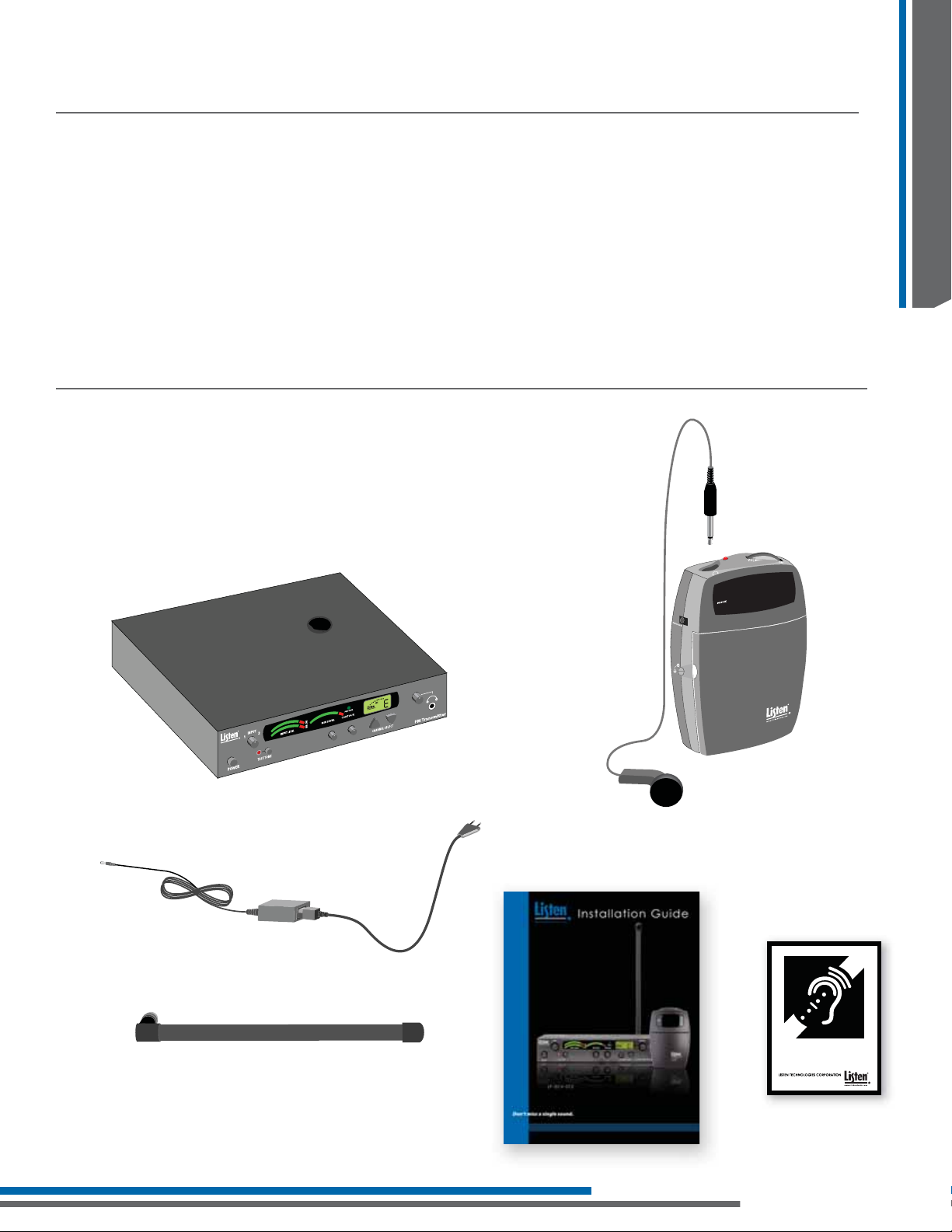
Value Package Contents
• (1) LT-803-072 Stationary 3-Channel FM Transmitter
• (4) LR-200-072 Standard 3-Channel FM Receiver
• (1) LA-123 90° Helical Antenna
• (4) LA-161 Single Ear Bud
• (1) LA-304 Assistive Listening Notifi cation Signage Kit
• (1) LA-207 12 VDC Power Supply
• (1) Installation Guide
LA-161 Single Ear Bud
Design Guide
3
0
8
-
T
L
LT-803-072 Stationary 3-Channel FM Transmitter
12 VDC Power Supply
LA-123 90° Helical Antenna
72
R
E
IV
E
C
E
R
D
R
A
D
N
A
T
S
LR-200-072 Standard 3-Channel FM Receiver
This facility is equipped with a
hearing assistance system.
Please ask for a receiver.
Installation Guide
LA-304 Assitive Listening
Notifi cation Signage Kit
3
Page 10

Page 11
Frequency Modulation (FM) Technology Overview
Frequency modulation or (FM) is a means of transmitting audio using electromagnetic waves. This same
technology is used by local FM radio stations to broadcast music. FM signals can travel through most barriers
– walls, fl oors, and ceilings. The distance a signal travels has many different variables such as Radio Frequency
(RF) output power, the type and placement of the antenna, and the broadcasted frequency. Unlike infrared,
FM transmission are not secure. This enables a receiver to travel further distances from the source. This section of
the manual will help you design a system that will get the best range and least amount of interference.
Audio Mixer
72
Design Guide
Audio Source
FM Transmitter
R
E
V
I
E
C
E
R
D
R
A
D
N
A
T
S
3
LT-80
FM Receiver
5
Page 12
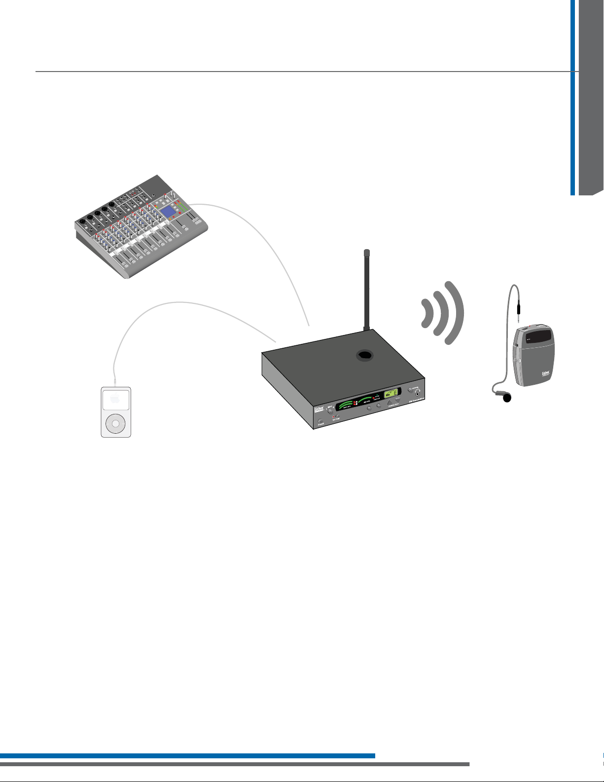
System Overview
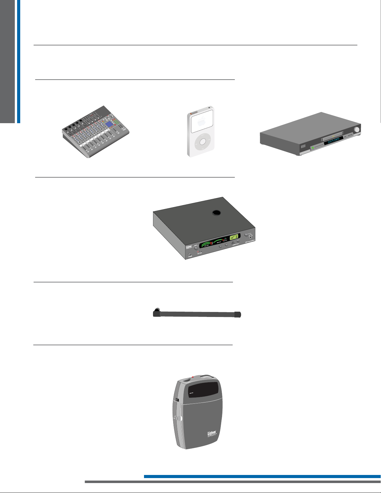
There are four main components to the Value Package – the transmitter, antenna, receiver and input source.
Design Guide
Input Source
Transmitter
The input source can be audio from a sound board, microphone or a personal audio source like a CD player,
MP3 player, computer, DVD, etc. Audio will be connected into the audio inputs of the Stationary Transmitter.
The LT-803-072 transmitter modulates the audio on an FM carrier and transmits the signal via an antenna.
LT-803-072 Stationary 3-Channel
FM Transmitter (72 MHz)
3
0
8
-
T
L
Antenna
The LP-3CV-072 includes the LA-123 90° Helical Antenna. This antenna has a BNC connector and should be
mounted on the back of the LT-803-072. For further antenna options see page 11.
Receivers
The LR-200-072 receiver captures the signal sent from the transmitter and outputs it into the LA-161 Single ear
bud. Listen offers a variety of receivers.
LA-123 90° Helical Antenna
72
R
IVE
CE
STANDARD RE
LR-200-072 Standard 3-Channel
FM Receiver (72 MHz)
6
Page 13
Key Concepts in Value Package Setup
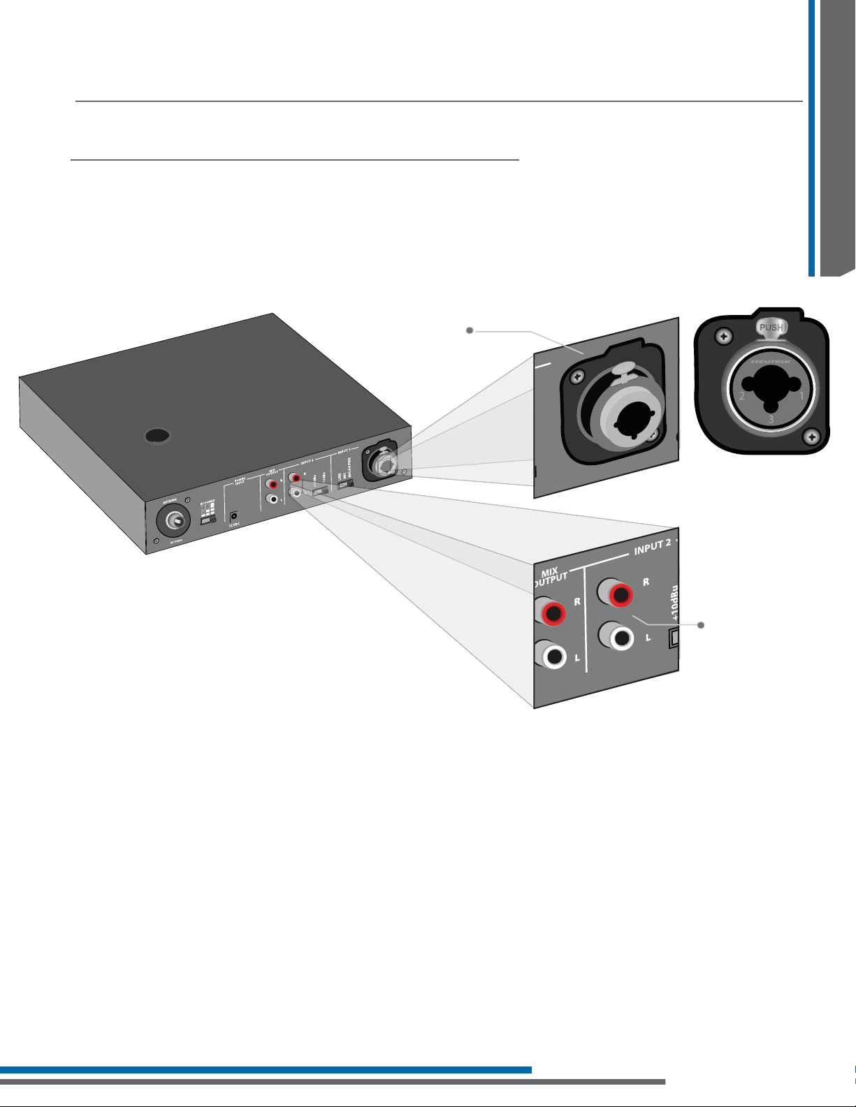
Input Selection
The LT-803-072 has two audio input options: Input 1 and Input 2. Input 1 is a balanced connection using either an
XLR or ¼ in. phono connector, and input 2 is two unbalanced phono connectors. Use Input 1 if you are using a
microphone or if you have a balanced connection such as a professional audio mixer (you can also use Input 1
for unbalanced connections). Use Input 2 to connect to an unbalanced audio source.
Balanced XLR or
1/4 in. phono connector
Design Guide
Unbalanced right
and left phono
connectors
Input 1: Connecting the audio source
Input 1 offers a choice of balanced XLR or ¼ in. phono connector. Plug an audio source into Input 1: move the
input select switch to the type of input source being used. Select “Line” for Line Inputs, “Mic” for dynamic
microphones or “Mic + PH Power” for condenser microphones. A balanced feed from a soundboard can also
be used with Input 1.
Input 2: Connect the audio source
Plug your unbalanced audio source into Input 2 and select the audio level switch for -10 dBu or +10 dBu to
match the audio level coming from your equipment.
7
Page 14
Design Guide
LT-803
LT-803
Key Concepts in Value Package Setup
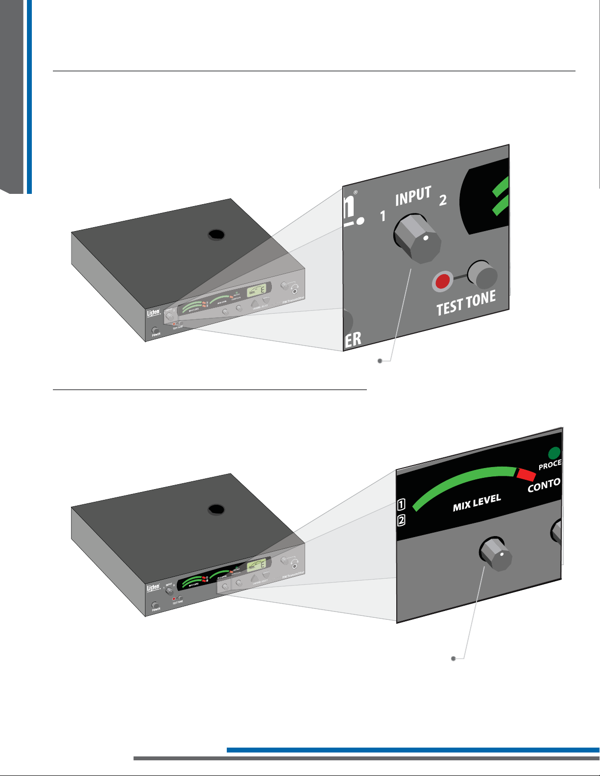
Using Multiple inputs
The LT-803-072 can accommodate multiple inputs simultaneously with the use of the input level
potentiometer. When multiple inputs are present, both input level lights will be activated.
LT-803
Mix Level
The mix level acts as the “master transmit” control. It will increase the transmit gain on the “mix” of the two
levels (if two levels are in use).
Input Level Knob
LT-803
Mix Level Adjustment
8
Page 15
Key Concepts in Value Package Setup
LT-803
Selecting Transmitting Frequencies
Use this section of the guide to choose the channel settings for the transmitter and receivers.
Find transmission channel(s)
The goal is to fi nd a transmission channel(s) that is free from interference. Interference comes from
transmitters and other outside FM signals.
Listen’s LT-803-072 o ers 3 di erent channels to choose from
With 3 different channels to choose from, the chance of fi nding an interference free channel is increased.
The best way to check for interference is to turn the LR-200-072 on and listen to each channel. Transmit on the
channel that has the least amount of noise.
Testing System
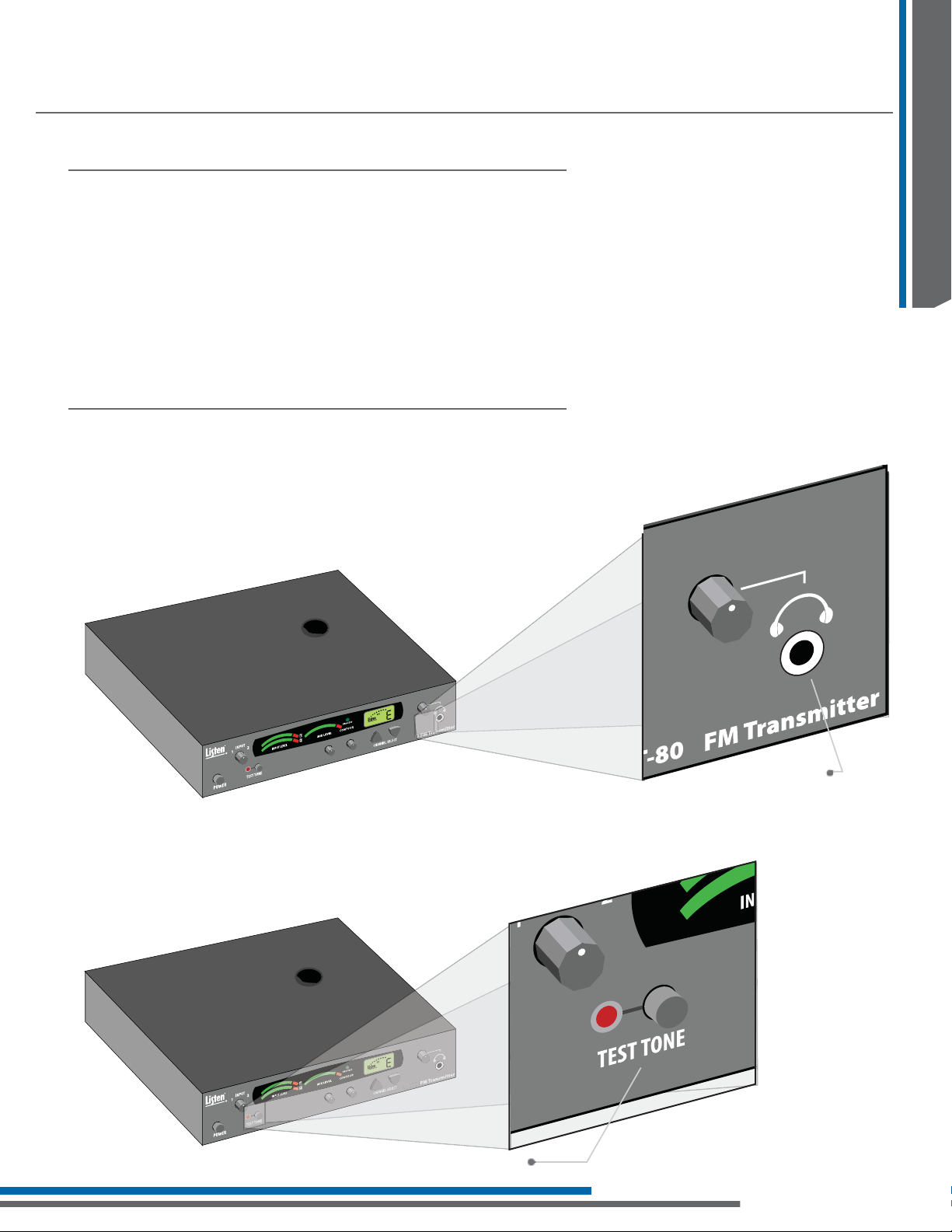
Monitor Jack
The headphone jack is used to monitor the mix of input 1 & 2. You can adjust the monitor level with the volume
knob. The headphone jack is a standard 3.5 mm jack.
Design Guide
LT-8 03
3
Headphone
Monitoring Jack
Test Tone
Use the test tone to transmit a 400 Hz tone. This tone will allow the end user to know if the system is transmitting
properly. All receivers should be able to hear this tone if tuned to the proper channel.
LT-803
Test Tone Button
9
Page 16
Key Concepts in Value Package Setup
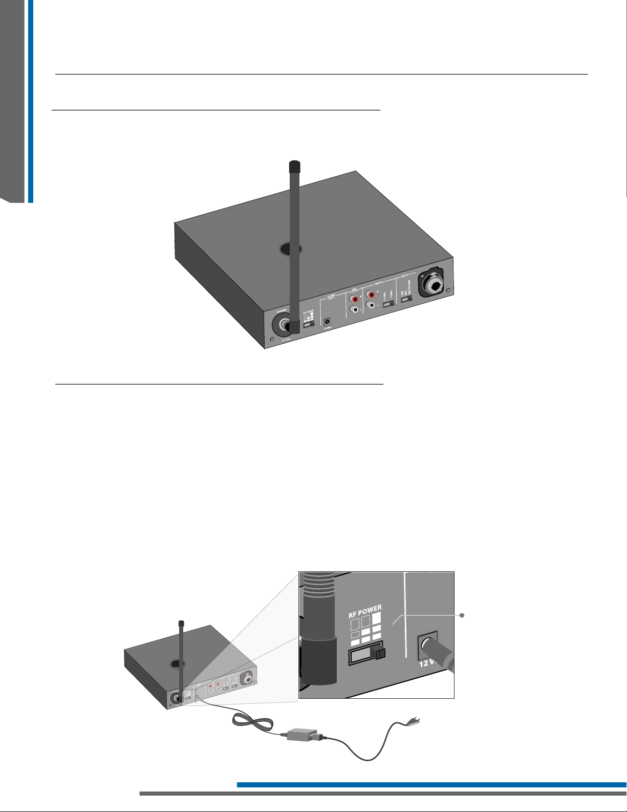
Antenna placement (rear)
Design Guide
Rear mounted antenna
Maximizing Transmission Range
Rear mounting the LA-123 90° Helical Antenna (72 MHz) will allow the transmitter to be moved if necessary.
For proper and dependable operation, Listen receivers need to receive a strong and consistent signal from the
originating transmitter. The following strategies should be used to maximize this signal:
Transmitting antenna
When designing and installing your system, keep in mind that the location of both the transmitting and
receiving antennas is critical to maximize broadcast range. Minimize the distance and remove any obstructions
between the transmitting and receiving antennas. Keep transmitting and receiving antennas (receiver earphone
cord) away from metal or conductive objects.
RF Power switch
Position the RF Power switch on the back of the LT-803-072 to full RF Power, unless lower power is necessary.
Low, med or high RF power
10
Page 17
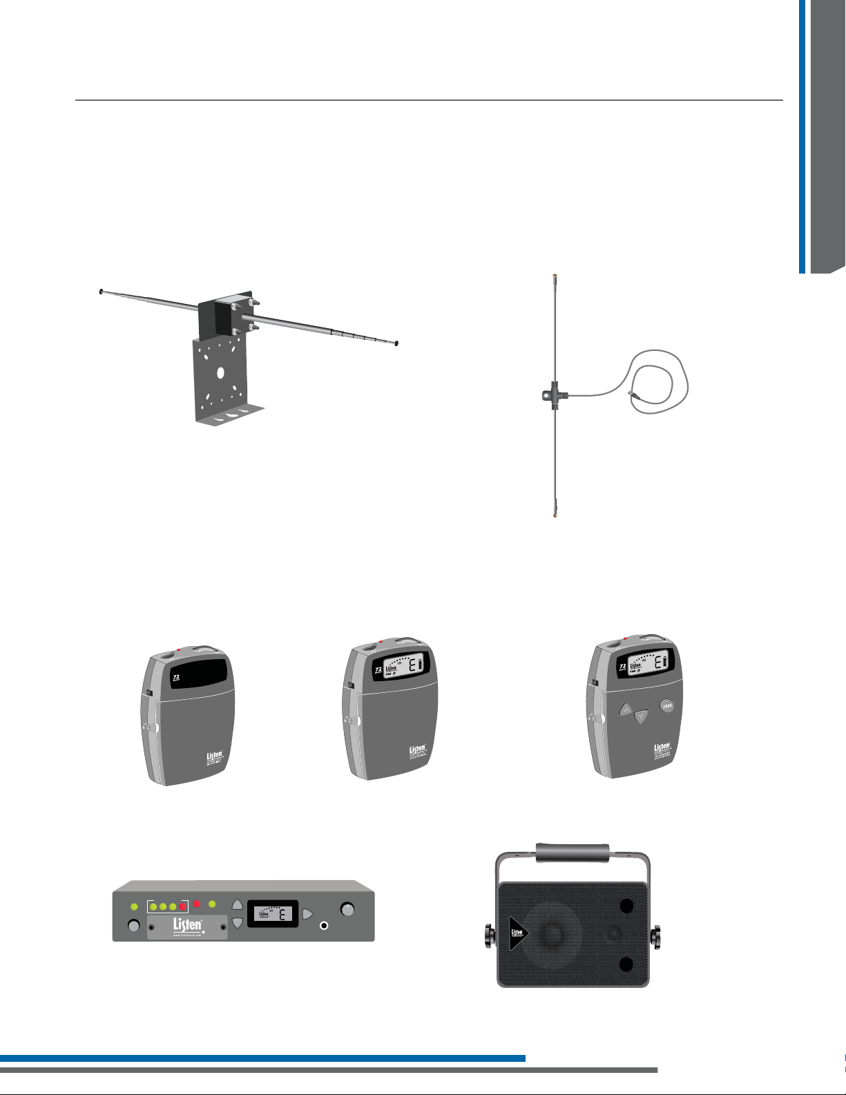
Alternative Options for Value Package Setup
Remote antenna
The LA-122 Universal Antenna Kit (72 and 216 MHz) and the LA-116 Coaxial Dipole Remote Antenna (72 MHz)
connect to the LT-803-072 and can be placed away from the transmitter for better range. They also allow the
unit to be rack mounted with the antenna remotely using the LA-326 Universal Rack Mounting Kit. Both the
LA-122 and LA-116 come with 25’ of black coaxial cable (RG-58).
Design Guide
ATTENTION: Long cable runs can result in signal degradation due to the “loss” characteristics of the cable.
Minimize cable runs as much as possible or use “low loss” RG-8 cable.
LA-122 Universal Antenna Kit (72 and 216 MHz)
LA-116 Coaxial Dipole
Remote Antenna (72 MHz)
Receiver Options
Listen offers a variety of portable and stationary receivers. Each receiver offers different features to help further customize your FM system.
ATTENTION: The SQ “Super Quiet” function must be turned OFF for better audio quality when using the LT-803-072
contained in this Value Package.
LR-300-072
Portable Digital FM Receiver
(72 MHz)
Up
LR-100
Power
Output Level
Mute
Squelch
RF Power
Channel
Down
LR-100-072
Stationary FM Receiver/ Power Amplifi er
(72 MHz)
LR-400-072
Portable Display FM Receiver
(72 MHz)
Speaker
Seek
Headphone
LR-500-072
Portable Programmable Display FM Receiver
(72 MHz)
LR-600-072
Wireless FM Receiver/Speaker
(72 MHz)
11
Page 18
Key Concepts in Value Package Setup
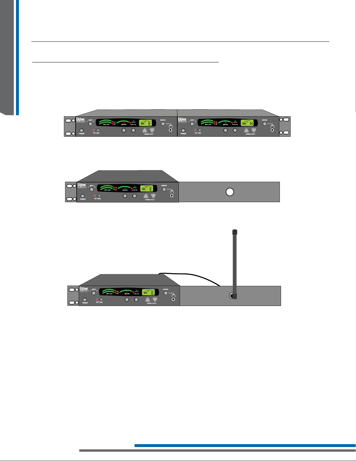
Rack Mounting the Transmitter
Design Guide
The LT-803-072 can be rack mounted if necessary. With the use of the Listen LA-326 Universal Rack Mount Kit,
you can mount one or two transmitters to the standard 19” rack. The rack mounted unit will take 1 ru of space.
LT-803 FM Transmitter
Rack Mount with dual units installed.
LT-803 FM Transmitter
Rack Mount with single unit installed.
LT-803 FM Transmitter
The antenna can also be in the front of the rack with the use of the LA-125 Antenna Kit for Rack Mount
(72 MHz) and the LA-326 Universal Rack Mounting Kit.
12
LT-803 FM Transmitter
Rack Mount with single unit and external antenna installed.
NOTE: The antenna may need to be remote mounted using the LA-122 Remote Antenna Kit if the transmitter(s) is
rack mounted. If a rack is metal, it is not recommended to have the antenna inside. Also, the depth of the rack and
equipment inside could prevent an antenna from being placed inside.
Page 19

Notes
Design Guide
13
Page 20

Design Guide
Notes
14
Page 21

Page 22

Page 23

Page 24

LT-803-072 User’s Manual Table of Contents
Specifi cations 20
Block Diagram 21
Quick Reference 22
Setup Instructions 23
Operating Instructions 25
Accessories 29
Notes 30
LT-800LT-803-072
Listen Confi gurations
• LT-803-072-01 (North America)
• LT-803-072-02 (Asia/UK)
• LT-803-072-03 (Euro)
LT-803-072 Package Contents
• (1) LT-803-072 Stationary 3-Channel FM Transmitter
• (1) LA-207 12 VDC Power Supply
• (1) Quick Reference Card
3
0
8
-
T
L
LT-803-072 Stationary 3-Channel FM Transmitter
12 VDC Power Supply
18
Quick Reference Card
Page 25

Page 26

LT-800LT-803-072
LT-803-072 Specifi cations
Architectural Specifi cation
The Stationary FM Transmitter shall be capable of broadcasting on one of any three channels – A (72.100 MHz),
E (72.900 MHz) or H (75.900 MHz). The transmitter shall have a SNR of 62 dB or greater. The output power shall be
adjustable to quarter, half or full. Channel tuning shall be capable of being locked. The device shall have an audio
frequency response of 50 Hz to 15k Hz, ± 3 dB at 72 MHz. It shall have two (2) mixing audio inputs. The device shall
have the following audio controls: input level, mix level and an adjustable low pass fi lter (contour). The device shall
have an audio processor that is capable of automatic gain control and limiting. The Listen LT-803-072 is specifi ed.
Speci cations LT-803-072
RF Frequency Range (A) 72.100, (E) 72.900, (H) 75.900
Number of Channels 3 wide band
Frequency Accuracy +/-.005% stability 32˚ to 122˚F (0˚- 50˚C)
Transmitter Stability 50 PPM
RF
Audio
Transmittion Range Up to 1,500 ft. (457.20 m)
Output Power 80,000uV at 3 m
Antenna Various antennas available
Antenna Connector BNC
Compliance FCC Part 15, Part 90, Industry Canada
** All system speci cations are wireless end-to-end
System Frequency Response 50 Hz - 15 kHz (±3 dB)
System Signal to Noise Ratio 62 dB (A-Weighted)
System Distortion <2% total harmonic distortion (THD) at 80% deviation
Audio Input 1
Audio Input 2 Rear panel, two (2) Phono connectors, unbalanced, -10/+10 dBu nominal input level adjustable, +30 dBu maximum, impedance 100k Ohms.
Audio Processing (Process) Compression can be turned on/o . Slope internally adjustable from 1:1 to 4:1. Default 2:1
Contour Cuts and boosts frequencies above 5 kHz
Combined Audio Output (Mix)
Headphone Output (monitor) Front panel, one (1) 3.5 mm (0.14 in.) stereo connector, unbalanced, adjustable output level, +3 dBu maximum, impedance 10 Ohm.
Input 1 and input 2, mixed output (rear panel), two (2) phono connectors, unbalanced, -10 dBu nominal output level, +15 dBu maximum,
Rear panel, one (1) Female-XLR and ¼ in. combo connector, balanced, 0/-55 dBu (line/mic) nominal input level
adjustable, -30/+21 dBu (line/mic) maximum input level, impedance 20k/1k Ohm (line/mic),
phantom power +12 VDC.
impedance 10 ohm.
Controls
Indicators
Power
Physical
Environmental
Front Panel Power, Test Tone on/o , Channel UP/DOWN, Input levels, Mix level, Contour, Monitor volume control
Rear Panel Input 1 Level (line, mic, mic-phantom power), Input 2 Level (-10/+10 dBu), RF Power level (low, mid, high)
Internal Adjustments Compression ratio for audio processor
Programming Process on/o . Channel lock
Input 1, Input 2, Mix Level VU Indicates Input 1, Input 2, and Mix audio levels; 10 segment LED’s (8 green, 2 red)
Processing Indicated by a green LED when on (front panel)
RF Power Indicated on the LCD (low, mid, high)
LCD Display Channel designation, lock status, RF Power Level, programming (front panel)
Test Tone Red LED illuminates when test tone is enabled
Power Supply In-line power supply. Listen part number LA-207 (line cord is determined by each country’s AC power standards
Power Supply Input Input: 100-240 VAC, 50-60 Hz. 0.4 A
Power Supply Output Output: 12 VDC, 1.3 A, 15.6 W
Power Supply Connector Output Connector: 0.02 in. (5.0 mm) OD, 0 .01 in. (2.5 mm) ID, barrel type
Power Supply Compliance UL, CE GS, TUV, RoHS
Dimensions (H x W x D) 8.50 x 1.75 x 9.12 in. (21.6 x 4.45 x 21.16 cm)
Color Dark grey with white silk screening
Unit Weight 2.6 lbs. (1.2 kg)
Unit Weight with LA-207-01 Power
Supply
Shipping Weight 4.5 lbs. (2.0 kg)
Rack Mounting
Temperature - Operation -10˚C (14˚F) to +40˚C (104˚F)
Temperature - Storage -20˚C (-4˚F) to +50˚C (122˚F)
Humidity 0 to 95% Relative Humidity, non condensing
One (1) rack space height, 1/2 rack space wide. One (1) or two (2) transmitters can be mounted in one rack space, optional rack mount
3.5 lbs. (1.6 kg)
(LA-326)
20
Page 27

LT-803-072 Block Diagram
POWER
On
Off
115/230VAC
50/60 Hz
Functions controlled by
the CPU Module
Universal Power
Supply (provided)
ANTENNA
BNC
Input 1 VU Meter
12VDC
Mic
Phantom Pwr
Mic
12VDC, 1.3A
Transmitter
RF Board
Low High
Mid
RF POWER
Line
Power Supply
CPU Module
Pre-emphasis Processing
Input 2 VU Meter
Input Level
Front Panel
Input Level
Select Mic-Phantom Pwr, Mic, Line
Input Level
Select Mic-Phantom Pwr, Mic, Line
MIX Level
VU Meter
+10dBu
Down
Listen LCD
Display Backlit
-10dBu
MIX LEVEL
Green LED
Volume
Compression Ratio
(internal adjustment)
On Off
OFF
Test Tone Button
ON
Red LED
MONITOR
LT-800LT-803-072
CONTOURPROCESS
Front Panel
Female XLR 1/4’
Combo Connector
1/Sleeve3/Ring2/Tip
Phono Phono
400Hz
INPUT 1 INPUT 2 MIX OUTPUT TEST TONE
21
Page 28

LT-803-072 Quick Reference
LT-800LT-803-072
Input 1 and 2:
Adjust audio input levels of
Input 1 and Input 2 here.
Test Tone: Activates a tone
to aid system setup.
Power Button: Turns unit On/Off.
RF Output Indicator:
Indicates transmitted
RF power level.
Mix Level: Shows mixed audio output level.
Input Level Indicators:
Shows audio Input 1
and Input 2 levels.
Mix Transmit Levels: Adjusts the amount of
mixed audio being transmitted.
PGM: Indicates the unit is in program mode.
Channel Display: Displays the current channel.
Process LED: Indicates audio processing mode is active.
Press and hold the down button for 10
seconds to activate program mode. Press
up button to toggle process On/Off.
LT-803 FM Transmitter
LCD Display: See LCD
display quick reference.
Contour: Equalization adjustment;
boosts or cuts high frequencies.
Monitor Jack: Plug in earphone(s)
to monitor audio.
Monitor Level:
Adjust the Monitor
output volume.
Channel Select UP/DOWN:
Use to select channel
(A,E,H). Buttons also used
for programming functions.
Power Input: Connect
power supply here.
RF Antenna Output:
BNC connector for
antenna (50 Ohm).
Lock Icon: Indicates the unit is locked on current
channel. Hold Channel up button for 3
seconds to lock On/Off channel.
Audio Outputs:
Input 1 and input 2
mixed for a line output.
RF Power Level:
Low, Med or
High RF power.
Top Mounted Antenna Output :
Screw terminal for top
mounted antenna.
Input 2: Unbalanced audio inputs (stereo or mono).
Input 2 Level Switch: Set switch to
match the level of your Input 2 source.
Input 1: Balanced input
Input 1 Level Switch: Set
switch for line or mic
level. Phantom power
available in Mic-PH
power position.
for connection of a line
level or microphone;
accepts either a XLR or
¼” phono plug.
22
Page 29

LT-803-072 Setup Instructions
Unpack the Product
1
Remove outer packaging and plastic cover. Verify all components are present and no physical
damage has occurred to the product.
Mount LT-803-072(s) in Rack (if desired)
2
If rack mounting the transmitter(s), install the optional rack mount kit (LA-326) according to the
instructions included with the kit.
Rack Mount with single unit installed.
Connect Antenna
3
Connect Power
4
LT-803 FM Transmitter
Connect antenna to rear of transmitter.
Plug the power supply into the power connector on the back panel. Plug the power supply into an
outlet. Only use a Listen approved power supply (12 VDC).
LT-803 FM Transmitter
Rack Mount with dual units installed.
LT-803 FM Transmitter
LT-800LT-803-072
23
Page 30

LT-800LT-803-072
LT-803-072 Setup Instructions
Set RF power
5
Set the RF POWER switch on the back of the unit to High, Medium, or Low (Level is indicated on the
LCD display by number of dots above Listen logo). The amount of transmitted RF power that you will
need depends on your application. If you are operating multiple transmitters in the same environment,
it is best to set the transmitter’s output power to its lowest level to reduce the possibility of interference.
Low, Med or High RF power
Connect Audio Inputs
6
The LT-803-072 has two (2) audio input options: Input 1 and Input 2. Input 1 is a balanced connection
using either an XLR or ¼ in. phono connector. Input 2 has two unbalanced mixing phono connectors.
Use Input 1 if you are using a microphone or if you have a balanced connection such as from a
professional audio mixer (you can also use Input 1 for unbalanced connections). Use Input 2 to
connect to an unbalanced audio source.
6A
Input 1
Input 1 offers a choice of balanced XLR or ¼ in. phono connector. Plug an audio source into Input 1: move
the input select switch to the type of input source being used. Select “Line” for Line Inputs, “Mic” for dynamic
microphones or “Mic + PH Power” for condenser microphones. A balanced feed from a soundboard can
also be used with Input 1.
XLR Wiring
Balanced
Audio
Source
Input from
Unbalanced
Audio
Source
1/4 in. Phono Wiring
Balanced
Sleeve
Top Ring Top Ring/Sleeve
Balanced
Audio
Source
Tip
Ring
Sleeve
Audio from
Unbalanced
Unbalanced
Audio
Source
24
6B
Input 2
Plug your unbalanced audio source into Input 2 and select the audio level switch for -10 dBu or +10
dBu, to match the audio level coming from your equipment.
Page 31

LT-803-072 Operating Instructions
LT-803
LT
Power Unit On
1
LT-803
Power Button
Select a Channel
2
Select the transmit channel (A, E, H) by pressing the channel select UP/DOWN buttons.
LT-800LT-803-072
Lock on Channel
3
LT-803
Channel select UP/DOWN
buttons
Once you determine your transmit channel, you can lock the transmitter on that channel. To lock
a channel hold the Channel Select UP button for 3 seconds until the padlock icon appears on the
display. To unlock, repeat this process and the padlock icon will disappear.
25
Page 32

LT-803-072 Operating Instructions
LT-
803
LT-
803
LT-800LT-803-072
Test Tone (if necessary)
4
Use the test tone to transmit a 400 Hz tone. This tone will allow the receiver to know if the system is
transmitting properly. All receivers should be able to hear this tone if tuned to the proper channel.
803
LT-
Adjusting Audio Levels
1
Adjust Audio Input Level
Turn the input knob counter-clockwise to add gain to Input 1. This will decrease gain to Input 2.
Turn input knob clockwise to add gain to Input 2. This will decrease gain to Input 1. If you have two
audio sources connected to Input 1 and 2, adjust the level of one input using the VU meter, then
adjust the output level of the other audio source. Adjust the input level until the left VU meter(s)
occasionally illuminate the red LEDs. Illumination of the red LEDs indicates the unit is in limiting.
Limiting is required so that the unit does not over-modulate the transmit signal. If you don’t want
any audio limiting to occur, make sure the red LEDs never illuminate. If you want a highly limited
signal, turn the audio gain up so the red LEDs illuminate often.
Test Tone Button
803
LT-
Audio Input Level Knob
26
Page 33

LT-803-072 Operating Instructions
LT-803
LT-
803
2
Adjusting the Contour knob
Turn the contour knob counter-clockwise if your audio source is mostly
voice. Turn the knob clockwise if your audio source is mostly music. The
contour knob adjusts the relative equalization of the unit. This
equalization boosts or cuts frequencies above 5 kHz.
803
LT-
LT-800LT-803-072
3
Adjust Mix Level
Contour Knob
Adjust the mix level until the right VU meter occasionally illuminates the
red LED. This is the level adjustment for the combined output from Input
1 and Input 2.
LT-803
Mix Level Adjustment Knob
27
Page 34

LT-803-072 Operating Instructions
LT-
803
LT-800LT-803-072
4
Process Mode
Process mode is used for Audio Gain Control (AGC). Press and hold the down button for 10 seconds to
activate program mode. Press up button to toggle process On/Off.
With the process mode enabled,
the LT-803-072 will automatically adjust for inconsistent signal input levels by raising or lowering the
signal level accordingly. This feature should be used in applications where a consistent sound level is
important and the input levels vary substantially. Typically you would not want to engage the Process
Mode when a speaker’s emphasis is critical to the message they are conveying.
803
LT-
Process
28
Page 35

Accessories for LT-803-072
v
Accessories
Antennas
LA-80 2-Way RF Antenna Combiner
LA-81 4-Way RF Antenna Combiner
LA-82 6-Way RF Antenna Combiner
LA-101 Helical Top Mounted Antenna (72MHz)
LA-106 Telescoping Top Mounted Antenna (72 MHz)
LA-116 Coaxial Dipole Remote Antenna (72MHz)
LA-122 Universal Antenna Kit (72 and 216 MHz)
LA-123 90˚ Helical Antenna (72 MHz)
LA-125 Antenna Kit for Rack Mount (72 MHz)
LA-123
LT-800LT-803-072
Power Supply
LA-207-01 12 VDC Replacement Power Supply for LT-803-072 (North America)
LA-207-02 12 VDC Replacement Power Supply for LT-803-072 (Asia, UK)
LA-207-03 12 VDC Replacement Power Supply for LT-803-072 (Euro)
LA-207
LA-127
LA-304
Cables/ Connectors
LA-112 RG-58 50 Ohm Coaxial Cable (Per ft.)
LA-113 RG-8 50 Ohm Low-Loss Coaxial Cable (Per ft.)
LA-115 RG-58 BNC Coupler
LA-127 RG-58 BNC Connector
LA-128 RG-8 BNC Connector
LA-390 RG-8/50 Ohm Preassembled Coaxial Cable (Per ft.)
LA-391 RG-58/50 Ohm Preassembled Coaxial Cable (Per ft.)
Miscellaneous
LA-304 Assistive Listening Notifi cation Signage Kit
LA-326 Universal Rack Mounting Kit
29
Page 36

Notes
Design Guide
30
Page 37

Page 38

Page 39

Page 40

LR-200-072 User’s Manual Table of Contents
Specifi cations 36
Block Diagram 37
Quick Reference 38
Setup Instructions 39
Accessories 42
Notes 43
Listen Confi gurations
• LR-200-072
LR-200-072 Package Contents
LT-800LR-200-072
• (1) LR-200-072 Standard 3-Channel FM Receiver (72 MHz)
• (1) Quick Reference Card
72
LR-200-072
Standard 3-Channel
FM Receiver
(72 MHz)
R
E
IV
E
C
E
R
D
R
A
D
N
A
T
S
Quick Reference Card
34
Page 41

Page 42

LR-200-072 Specifi cations
Architectural Specifi cation
The FM receiver shall be capable of receiving on three wide band channels. The receiver shall have a
SNR of 62 dB or greater. The device shall have an audio frequency response of 50 Hz to 15 KHz, ± 3 dB
at 72 MHz. The device shall incorporate a stereo headset jack that allows the user to plug in either a
mono or stereo earphone(s). The unit shall operate with (2) AA batteries. The receiver shall incorporate
automatic battery charging circuitry for recharging of NiMH batteries. The device shall have a
switchable option for the use of (2) alkaline or (2) NiMH batteries. The Listen LR-200-072 is specifi ed.
Specifi cations LR-200-072
RF Channel Range (A) 72.100, (E) 72.900, (H) 75.900
Number of Channels 3 wide band
Sensitivity .6 uV typical, 1 uV maximum for 12 dB sinad
RF
Audio
Frequency Accuracy +/-.005% stability 32˚ to 122˚F (0˚ - 50˚C)
Antenna Uses earphone cable
Squelch None
Compliance FCC Part 15, Industry Canada, RoHS
** All system specifi cations are wireless end-to-end
System Frequency Response 50Hz - 15kHz (+/-3dB)
System Signal to Noise Ratio 62 dB
System Distortion <2% total harmonic distortion (THD) at 80% deviation
Output
3.5 mm (0.14 in.) connectors, unbalanced, 0 dBu nominal output level, 16 mW maximum,
impedance 32 Ohms
LT-800LR-200-072
Environmental
Controls
Indicators
Power
Physical
User Controls ON/OFF, volume
Set up Controls
(battery compartment)
Programming None
LED Red, illuminated when unit is on or to indicate charging, fl ashes when batteries are low.
LCD Display None
Battery Type Two (2) AA batteries, alkaline or NiMH
Battery Life (Listen Batteries) 120 hours alkaline (LA-361), 75 hours NiMH rechargeable (LA-362)
Battery Charging (NiMH only) Fully automatic, 10-12 hours under normal use.
Power Supply
Power Supply Connector
Power Supply Compliance RoHS, WEEE, UL, PSE, CE, CUL, TUV, CB compliant
Dimensions H x W x D 4.25 x 2.75 x 1.50 in. (10.8 x 7.0 x 3.8 cm)
Color Dark Grey with white silk screening and dark lens
Unit Weight 3.1 oz. (88 g)
Unit Weight with batteries 5.2 oz. (147 g)
Shipping Weight 5.8 oz. (164 g)
Door Manually lockable. SEEK behind the door.
Temperature - Operation 14˚ to 104˚F - (-10˚ to 40˚C)
Temperature - Storage -4˚ to 122˚F - (-20˚ to 50˚C)
Humidity 0 to 95% relative humidity, non-condensing
I/P 120VAC; O/P 7.5VDC 250 mA; drop in contact points for use with charging cases.
2.3 mm OD by 0.7 mm ID, barrel type connector, 7.5 VDC, center positive <250 mA.
Alkaline/NiMH batteries, channel switch
Power supply not included (LA-202)
Drop in contact points for use with Listen charging cases.
** Specifi cations are subject to change without notifi cation
36
Page 43

LR-200-072 Block Diagram
115/230VAC
50/60 Hz
LCD Display
Universal
Power Supply
(not included)
ANTENNA
RF
de-modulation
Power Supply
CPU Module
Alkaline
(2) AA Batteries
ALkaline or NiMH
NiMH
de-emphasis
Up
Down
Seek
Power charge indicator
Red LED
POWER
On
Off
VOLUME
3.5 mm Connector
Tip
Ring
Sleeve
LR-200-072
37
Page 44

LR-200-072 Quick Reference
Alkaline
Battery Select
Channel
Sel
ect
NiMH
3.5 mm Output Jack: Connect a Listen earphone(s) here.
LED: When lit, unit is On or charging.
When batteries are low, the LED fl ashes.
72
Power/Charging Port
Front Door Lock
On/Off and Volume Control Dial
Battery Select Switch:
Choose the type of batteries
being used - Alkaline or NiMH.
Channel Select Switch:
There are 3 separate channels
(A, E, H) available.
LT-800LR-200-072
Battery Compartment:
Place two (2) AA batteries in
compartment. Be sure to
follow polarity pattern.
38
Page 45

Alkaline
Bat
tery Se
lec
t
Cha
nn
el
Sel
ect
NiMH
LR-200-072 Setup Instructions
Alkaline
Bat
tery
Se
lec
t
Cha
nn
el Select
NiMH
t
iMH
t
tery
Se
lec
e
Se
lec
a
Se
lec
a
1
Remove the product
Remove outer packaging and plastic cover. Inspect for physical damage. If damage is apparent,
please contact the dealer from which the product was purchased or Listen Technologies
Corporation technical support for assistance (refer to page 55 for contact information).
Open the front access door
2
If locked, use a small screwdriver to unlock the door locks on both sides of the unit. To unlock
the door, rotate the lock ¼ turn counterclockwise. Grip the two tabs with your thumb and
index fi nger and pull the door downward. DO NOT place batteries in the unit at this time.
72
Select Battery Type
3
Two types of batteries may be used: The unit is shipped with the switch in the Alkaline position.
Use a pen or small screwdriver to select the battery type.
72
LR-200-072
BATTERY SELECT
Battery Select Switch
WARNING: Do not place the BATTERY switch in the NiMH position if you are not using
Nickel Metal Hydride Batteries. The NiMH position will attempt to charge
any batteries in the unit, even if they are not the proper type. Charging
non-Nickel Metal Hydride (NiMH) batteries will result in physical harm,
destruction of property and/or fi re.
CAUTION: If you are using any battery type other than rechargeable Nickel Metal
Hydride (NiMH) batteries, make sure the BATTERY selection switch is in the
alkaline position.
39
Page 46

LR-200-072 Setup Instructions
Alkaline
Bat
tery
Se
lec
t
Cha
nn
el
Select
NiMH
Channel Select
4
Set channel select switch to desired channel (A, E, H). Make
sure that the channel on both receiver and transmitter are the
same.
Channel Select Switch
Place Batteries in Unit
5
Insert two AA batteries making note of the battery
polarity shown in the battery compartment, and again
verifying that the BATTERY SELECT switch is in the correct
position for the batteries you are using. (Alkaline should
be selected for all battery types other than NiMH).
NOTE: Listen provides industrial strength AA alkaline
batteries (LA-361) and high performance AA
Nickel Metal Hydride batteries (LA-362). These
may be purchased from your Listen dealer.
72
+
+
-
-
+
+
-
-
LT-800LR-200-072
40
Connect an Earphone or Headset
6
Your headset or earphone will connect to the jack on the top of the unit.
Either mono or stereo connectors may be used with a Listen receiver. Make
certain you push the plug all the way into the jack.
72
STANDARD RECEIVER
Page 47

LR-200-072 Setup Instructions
7
Turn the Unit On
Receivers are turned on by rotating the volume dial
counterclockwise. The red LED on top of the unit will illuminate.
If it does not, make sure you have installed the batteries
correctly and that you are using fully charged batteries.
Adjust the volume control
8
Use the control dial on the top of the unit to adjust the volume
to a comfortable level.
72
R
E
IV
E
C
E
R
D
R
A
D
N
A
T
S
72
LR-200-072
STANDARD RECEIVER
41
Page 48

Accessories for LR-200-072
Accessories
Headphones
LA-161 Single Ear Bud
LA-162 Stereo Ear Bud
LA-164 Ear Speaker
LA-165 Stereo Headphones
LA-166 Neck Loop
LA-170
LA-202
LA-266
LA-170 Behind-the-Head Stereo Headphones
LA-171 Noise Canceling Headphones
Power/Charging Supplies
LA-202 Power/Charging Supply for FM Portable Products
Cables
LA-265 Consumer Camcorder Cable
LA-266 Professional Camcorder Cable
LA-275 Sacrifi cial Cable
LT-800LR-200-072
Charging/ Carrying Cases with Removable Lid
LA-311-01 16-Unit Portable FM Product Charging/Carrying Case (North America)
LA-317-01 4-Unit Portable FM Product Charging/Carrying Case (North America)
LA-321-01 8-Unit Portable FM Product Charging/Carrying Case (North America)
LA-323-01 4-Unit Portable FM Product Charging/Carrying Case w/Removable Lid (North America)
LA-324-01 8-Unit Portable FM Product Charging/Carrying Case w/Removable Lid (North America)
LA-325-01 16-Unit Portable FM Product Charging/Carrying Case w/Removable Lid (North America)
LA-321
Carrying Cases
LA-306 Soft Case (72 MHz & 216 MHz only)
LA-313 16-Unit Portable FM Product Carrying Case
LA-318 4-Unit Portable FM Product Carrying Case
LA-319 Protective Pouch for Portable FM Products
LA-320 Confi gurable Carrying Case
LA-322 8-Unit Portable FM Product Carrying Case
LA-320
Miscellaneous
LA-330 Portable Unit Lanyard
LA-361 High Capacity AA Alkaline Batteries (2)
LA-362 Rechargeable AA NiMH Batteries (2)
42
LA-362
Page 49

Notes
LR-200-072
43
Page 50

Notes
LT-800LR-200-072
44
Page 51

Page 52

Page 53

Page 54

Supplementary Information Table of Contents
Battery Charging Information 50
Frequency Chart 51
Troubleshooting 52
Frequently Asked Questions 54
Compliance, Warranty and Contact Information 55
Notes 57
LT-800Supplementary
48
Page 55

Page 56

Battery Charging Information
The LR-200-072 receiver uses a trickle charging method. When one of these receivers is placed into a Listen charging case any NiMH
batteries will be charged. The entire charging process takes 10-12 hours under normal conditions.
During the charging cycle, the red LED on top of the Listen product will remain illuminated.
When not using the receiver, it is recommended to leave the unit in the charging case or plugged into the LA-202 power source.
If the unit is not on the charger, the battery will lose up to 20% of its charge per month.
NOTE: Listen provides 2300 mAH (milli-Amp-hour) constant current NiMH Nickel Metal Hydride batteries. These may
be purchased from Listen (LA-362).
Charging with a drop-in charger
To charge the batteries using a drop-in charging case, simply place the unit into a slot in the charging case
and connect the case to power. Make sure the unit is fully seated in its slot.
72
R
E
V
I
E
C
E
R
D
R
A
D
N
A
T
S
Charging with the LA-202
IMPORTANT: DO NOT ATTEMPT TO CHARGE ANY TYPE OF BATTERY OTHER THAN NiMH (NICKEL METAL HYDRIDE) with
IMPORTANT: In order to charge NiMH batteries, the BATTERY SELECT switch in your Listen product must be set to the
LT-800Supplementary
WARNING: The case lid MUST be open or removed while the units are charging. The charging process generates
To charge batteries using the LA-202 7.5 DC Power Charging Supply, plug the
transformer into the jack marked PWR/CHG and plug into AC Power source.
The unit can operate while batteries are being charged If the battery select
switch is in the NiMH position and NiMH batteries are placed inside.
72
ER
RECEIV
ARD
D
STAN
your Listen equipment. Alkaline batteries may explode when connected to a charger. Other risks of
charging non-NiMH batteries include destruction of property or fi re.
NiMH setting. Use a pen or small screwdriver to move the switch (located in the battery compartment)
to the proper position.
heat. Air ventilation is required. It is best to store your charging case at room temperature away from
heat sources and direct sunlight
50
Page 57

Frequency Chart
Channel Frequency (MHz)
A 72.100
E 72.900
H 75.900
51
Supplementary
Page 58

Troubleshooting
Troubleshooting
The LT-803-072 has no power.
Make sure the 12 VDC power transformer is connected to a power source and is connected to the
jack marked “Power Input”. Make sure the PWR button is pressed in.
There is no audio or the audio level is too low.
1. Make sure that your audio source is properly connected to Input 1 and/or Input 2. The Input 1 or
Input 2 switches must be in the correct position for the appropriate input level. For example: if you
are using the output of a mixer on Input 2, the switch should be in the -10 dBu position. If it were to be
in the +10 dBu position, the level would be too low. Also, check the Input knob to ensure it is properly
adjusted. You should be able to see illuminated lights on the VU meter on Input 1 or Input 2
corresponding with the input level of the audio source. You can listen to the audio source by
connecting a headset to the front panel jack and adjusting the Monitor volume control.
2. If the level of audio into the transmitter is low and cannot be corrected using the level input switches,
the audio processor can be turned on to boost the signal (see page 28 for description of Process
Mode).
The audio is distorted.
Check to make sure you have the input level select switches in the proper position. You may be
providing too much audio level for the input stage to handle.
There is hum in the audio.
Make sure you have properly grounded the audio source to the LT-803-072. Check the connections
from the audio source to the LT-803-072. If you can, try to use a balanced audio source - this will
reduce the chance of creating hum. Connect a ground wire from the LT-803-072 to ground and/or to
the ground of the source audio.
There is a tone.
The Test Tone button has been pressed (its LED light is on). Push the Test Tone button to turn off the tone.
The Audio Input 1 sounds “tinny”.
If you are using an unbalanced audio source, make sure Pin 3 on the XLR or the ring on the ¼ in. plug is
grounded .
I cannot pick up the signal on the receiver.
Check to make sure the receiver and the transmitter are on the same channel. Make sure the
LT-803-072 has an antenna connected. Ensure that the receiver has an earphone connected.
I can pick up the signal on the receiver, but it sounds like it’s not tuned in.
Check to make sure the transmitter and receiver are on exactly the same channel. It’s a good idea to
lock the channels once they have been set. To lock the LT-803-072, press the UP button for 3 seconds.
There is not suffi cient range.
First make sure that the receivers you are using are operating properly, then make sure that you have
an antenna connected either to the top of the LT-803-072 transmitter or connected to the back of the
unit (but not both!). The antenna should be as high as possible and free of obstacles. In addition, make
sure you are using the correct antenna type for your unit. You might want to use a remote antenna
[LA-122 Universal Antenna Kit (72 MHz) or LA-116 Coaxial Dipole Remote Antenna (72 MHz)] that can
be mounted on a mast or wall. Try using different frequencies to fi nd one with less interference.
(see page 25 for information regarding channel selection)
LT-800Supplementary
52
Page 59

Troubleshooting
Troubleshooting
There is interference in my transmission.
Ensure that the transmitter and receivers are on the same channel. Verify that there are no other
transmitters on the same channel or a close channel to the one exhibiting interference. Try
different channels until you fi nd a clear channel. Please contact Listen for more ideas on
troubleshooting the interference.
End users are adjusting the unit.
First, lock the channel on the LT-803-072 by pressing and holding the channel select UP button for 3
seconds. Consider removing the Input, Mix Level and Contour knobs. You can order a rack mount
kit (LA-326) from Listen which offers a security cover that will limit access to the unit.
I am using another manfactures receiver with the LT-803-072.
Listen’s 72 MHz equipment is compatible with any other 72 MHz equipment.
Several transmitters are operating in the same environment.
Be sure each transmitter is using a seperate frequency (A,E,H).
Can I have two antenna’s connected to my transmitter.
No. The LT-803-072 transmitter can use only one antenna connection at a time. You may connect
either a top mount antenna through the top antenna port, or a remote antenna connected to
the BNC connection on the rear of the unit. If multiple antennas are simultaneously connected to
both ports the transmitter will have extremely poor broadcast performance and range.
53
Supplementary
Page 60

Frequently Asked Questions
Frequently Asked Questions
What is the range of the LT-803-072 transmitter?
Q
Line of site up to 1000 ft. (304.8 m).
A
Does the LT-803-072 include the rack mount?
Q
No, but an LA-326 Universal Rack Mounting Kit is available for purchase.
A
Do I need a transmitter for each audio source?
Q
Yes.
A
Is there a limit to the number of transmitters I can use in one room?
Q
Yes, a maximum of 3.
A
How many receivers can I have on a system?
Q
As many as you want. The transmitter simply transmits a signal and you can have as many
A
receivers pick that signal up as necessary. It’s like a radio station transmitting and the receivers are
the radios tuning into the “channel”.
Q
Q
Q
Q
Q
Q
Q
LT-800Supplementary
What is the warranty of LIsten transmitters?
Limited lifetime warranty. The following cases will void the warranty:
A
• Misuse, dropping, or any other noticeable cosmetic damage.
What are the differences between the LR-200 and other Listen receivers?
The LR-200 offers three (3) frequencies and can be changed inside the door of the receiver via a switch.
A
The LR-200 does not have an LCD screen, the ability to SEEK for open frequencies, SQ (Super Quiet) or
programmability. Also, the Signal to Noise is 62 dB compared to 80 dB on Listen’s other receivers.
Can the LR-200 be used with the LT-800-072?
Yes. The SQ function on the transmitter must be turned off and the transmitter can only be used with one
A
of the three optional frequencies (A, E, H).
Can the LR-200 be used with the LT-700-072?
No.
A
What is the battery life of the LR-200-072
120 hours alkaline. 75 hours NiMH.
A
What is the charge time of the LR-200-072 using two (2) NiMH batteries?
10-12 hours under normal use.
A
What is the warranty of Listen recievers?
Limited lifetime warranty. The following cases will void the warranty:
A
• Misuse, dropping, or any other noticeable cosmetic damage.
• Charging alkaline batteries instead of NiMH.
• Overheating the charging process by closing the lid on the charging case.
54
Page 61

Compliance Notice and FCC Statement
Compliance Notice
This device complies with part 15 of the FCC Rules. Operation is subject to the following two conditions:
(1) These devices may not cause harmful interference, and (2) these devices must accept any
interference received, including interference that may cause undesirable operation.
Listen’s LT-800 Transmitter (216 MHz only)
Listen’s LT-800 transmitter is authorized by rule under the Low Power Radio Service (47 C.F.R. Part 95) and
must not cause harmful interference to TV reception or United States Navy SPASUR installations. You do
not need an FCC license to operate these transmitters. These transmitters may only be used to provide:
auditory assistance to persons with disabilities, persons who require language translation, or persons in
educational settings; health care services to the ill; law enforcement tracking services under agreement
with a law enforcement agency; or automated maritime telecommunications system (AMTS) network
control communications. Two-way voice communications and all other types of uses not mentioned
above are expressly prohibited.
This device must be installed by a trained audio professional or certified dealer of Listen. The user
can’t make any modifications to the unit without expressed written consent of Listen Technologies
Corporation. Any modifications made will void the FCC compliance, Listen warranty and the users
authority to operate Listen’s equipment.
FCC Statement
This equipment has been tested and found to comply with the limits for a class B digital device, pursuant
to part 15 of the FCC Rules. These limits are designed to provide reasonable protection against harmful
interference in a residential installation. This equipment generates, uses and can radiate radio frequency
energy and if not installed and used in accordance with the instructions, may cause harmful interference
to radio communications. However, there is no guarantee that interference will not occur in a particular
installation. If this equipment does cause harmful interference to radio or television reception, which can
be determined by turning the equipment off and on, the user is encouraged to try to correct the
interference by one or more of the following measures:
Reorient or relocate the receiving antenna.
Increase the separation between the equipment and receiver.
Connect the equipment into an outlet on a circuit different from that to which the receiver is
connected.
Consult the dealer or an experienced radio/TV technician for help.
This equipment has been certified to comply with the limits for a class B computing device, pursuant to
FCC and IC Rules. In order to maintain compliance with FCC and IC regulations, shielded cables must
be used with this equipment. Operation with non-approved equipment or unshielded cables is likely to
result in interference to radio and TV reception. The user is cautioned that changes and modifications
made to the equipment without the approval of manufacturer could void the user’s authority to operate
this equipment.
Supplementary
55
Page 62

Warranty and Contact Information
Warranty
Listen Technologies Corporation (Listen) warrants its transmitters and receivers (models LT-700, LT-800, LT-803, LR-42,
LR-44, LR-100, LR-200, LR-300, LR-400, LR-500 and LR-600) to be free from defects in workmanship and material under
normal use and conditions for the useful lifetime of the product from date of purchase.
Listen warrants it’s Stationary IR Radiators (LA-140) to be free from defects in workmanship and material under
normal use and conditions for three years from the date of purchase.
Listen warrants its Noise Canceling Microphone (LA-270) to be free from defects in workmanship and material under
normal use and conditions for one year from date of purchase.
Listen warrants its Charging/Carrying Cases (LA-311, LA-313, LA-317, LA-318, LA-320, LA-321, LA-322, LA-323, LA-324,
LA-325) to be free from defects in workmanship and material under normal use and conditions for one year from
date of purchase.
All other products and accessories are warranted for 90 days from date of purchase.
This warranty is only available to the original end purchaser of the product and cannot be transferred. Warranty is
only valid if warranty card has been returned, or online warranty registration, has been completed within 90 days
of purchase. This warranty is void if damage occurred because of misuse or if the product has been repaired or
modifi ed by anyone other than a factory authorized service technician. Warranty does not cover normal wear and
tear on the product or any other physical damage unless the damage was the result of a manufacturing defect.
Warranty does not include inbound freight costs. Listen is not liable for consequential damages due to any failure
of equipment to perform as intended. Listen shall bear no responsibility or obligation with respect to the manner of
use of any equipment sold by it. Listen specifi cally disclaims and negates any warranty of merchantability or fi tness
of use of such equipment including, without limitation, any warranty that the use of such equipment for any purpose
will comply with applicable laws and regulations. The terms of the warranty are governed by the laws of the state of
Utah.
In the fi rst ninety days after purchase, any defective product will be replaced with a new unit. After 90 days, Listen
will, at its own discretion either repair or replace transmitters and receivers with a new unit or a unit of similar type
and condition. Product that is not covered under warranty shall be repaired or replaced with a unit of similar type
and condition based on a fl at fee.
This limited warranty, prices and the specifi cations of products are subject to change without notice.
Contacting Listen
If technical service is needed, please contact Listen. Pre-authorization is required before returning Listen products. If products were
damaged in shipment, please contact the carrier, then contact Listen for replacement or repair requirements payable by the
carrier.
All Listen European markets are supported through the Listen Technologies GmbH offi ce located in Oberasbach, Germany. For
more information on Listen solutions, contact Listen Technologies at +1.801.233.8992, +1.800.330.0891 North America,
Listen Technologies GmbH at +49 911 955159-0 or visit www.listentech.com. For Europe, Middle East, Africa and India offi ce visit
www.listentech.de.
14912 Heritagecrest way
Bluffdale, Utah U.S.A. 84065-4818
+1.801.233.8992
+1.800.330.0891
+1.801.233.8995
support@listentech.com
www.listentech.com
North America
Fax
Listen Technologies GmbH
Jasminstr.16, 90522 Oberasbach, Germany
+49 911 955 159 0
+49 911 955 159 40
support@listentech.de
www.listentech.de
Europe
Fax
LT-800Supplementary
56
Page 63

Notes
57
Supplementary
Page 64

Notes
LT-800Supplementary
58
Page 65

Listen Technologies Corporation
14912 Heritagecrest Way
Bluffdale, Utah 84065-4818, U.S.A.
+1.801.233.8992
+1.800.330.0891
+1.801.233.8995
North America
Fax
www.listentech.com
info@listentech.com
Listen Technologies GmbH
Jasminstr. 16
905 22 Oberasbach, Germany
+49 911 955159 0
+49 911 955159 40
EMEAI
Fax
www.listentech.de
info@listentech.de
© 2008 Listen Technologies Corporation
®
All Rights Reserved 20080129
 Loading...