

Page 1
ListenTALK
USER MANUAL
Mobile Two-Way
Communication
System
www.listentech.com
Page 2

Dear Valued Customer,
Thank you for choosing Listen! We are dedicated to providing you with
the highest quality products available, and take pride in delivering
outstanding performance to ensure you are completely satised.
We independently certify each of our products to the highest quality
standards and back them with a limited lifetime guarantee. We are
available to answer any questions you might have during installation or
in the operation of our products. At Listen, it’s all about you, should you
have any comments or suggestions we’re here to listen.
Here’s how to reach us:
+1.801.233.8992 +1.800.330.0891 North America
+1.801.233.8995 fax support@listentech.com www.listentech.com
Thank you and enjoy your listening experience!
Best regards,
Russell Gentner and the Listen Team
2
Page 3

LISTENTALK TABLE OF CONTENTS
4 Introduction
5 Components
5 Denitions
6 Safety Cautions!
7 LK-1 Quick Reference
9 LKR-11 Quick Reference
11 LKR-12 Quick Reference
13 Docking Station Tray Quick Reference
15 Specications
21 System Setup
23 Unit – General Operation
24 System Talkback Modes
25 ListenTALK Security
25 Unit Programming
28 Docking Station Operation
28 Advanced Features
29 Software Suite
29 Accessories
29 Applications
30 System Troubleshooting
32 Compliance Notice and FCC Statement and Industry Canada Statements
32 Warranty
32 Contact Information
3
Page 4

INTRODUCTION
ListenTALK is a portable wireless collaboration system designed for group communications in
a variety of applications including Training and Collaboration, Assistive Listening, Guided Tour
Groups, Language Interpretation and Translation, Event Production and Sports Intercom.
SIMPLE AND VERSATILE
ListenTALK systems are simple to purchase and congure and they are highly versatile.
Create a ListenTALK Group with the push of a button in the Docking Station, with the click of a
mouse in the ListenTALK Software Suite or on the go using built-in Near Field Communication
(NFC) technology. Use as many as ten simultaneous groups in the same area.
ListenTALK Transceivers are simple to operate and Leaders can easily designate one of three
Participant modes to meet the needs of any venue or application.
RELIABLE AND SECURE
Instead of the overcrowded 2.4 GHz frequency, ListenTALK operates on the 1.9 GHz band
in full duplex and utilizes frequency hopping and spread spectrum technology to increase
reliability and reduce interference. Headset styles are available for use in quiet or noisy
environments.
Listen understands that your security matters, so each ListenTALK is equipped with a
multilayer security protocol consisting of a 40-bit (pin free) group subscription, 32-bit
authentication and a 64-bit encryption scheme assuring secure conversations.
WELCOME TO LISTENTALK!
ListenTALK is Simple, Versatile, Scalable, Secure and Reliable!
4
Page 5
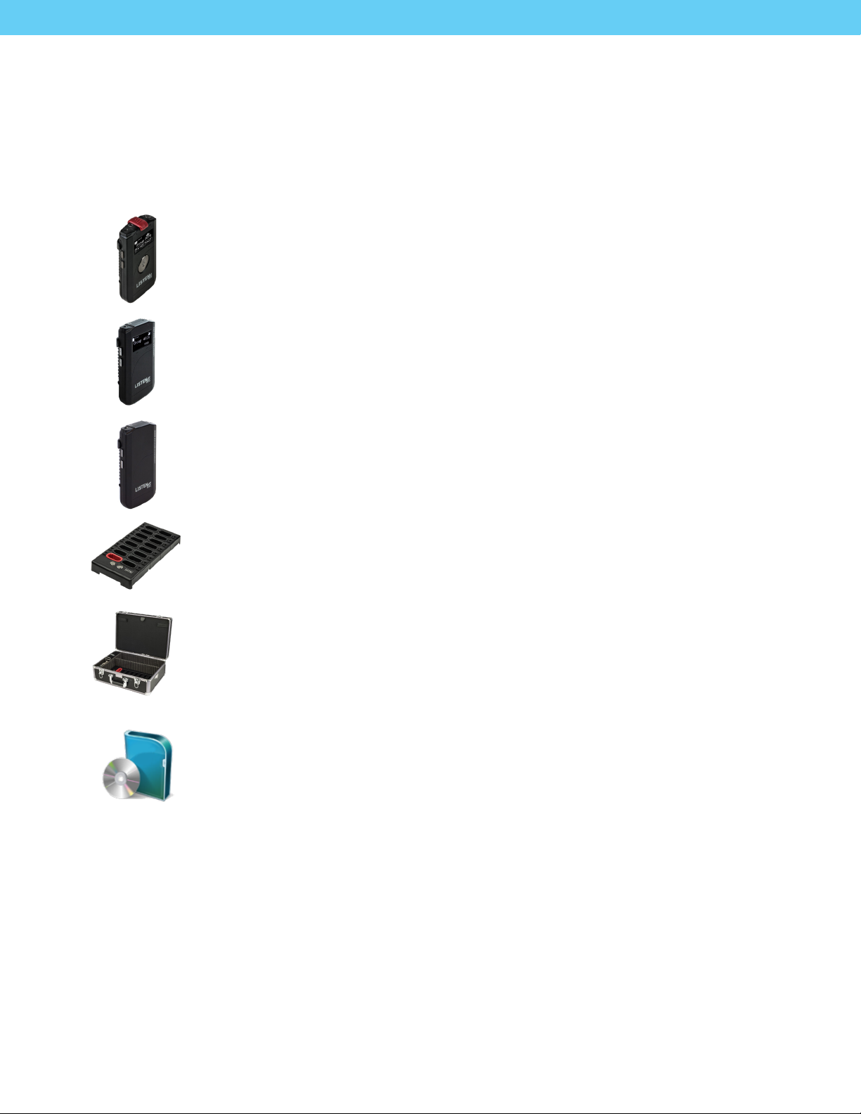
LISTENTALK COMPONENTS
ListenTALK
The term ListenTALK refers to the system as a whole and a system is made up of dierent
ListenTALK components.
LK-1 ListenTALK Transceiver
The term LK-1 ListenTALK Transceiver refers to a ListenTALK hand-held unit that
can both transmit audio to and receive audio from a ListenTALK group. The LK-1
Transceiver can be used as a group leader, Sub-Leader or Participant unit.
LKR-11 ListenTALK Receiver Pro
The term LKR-11 ListenTALK Receiver Pro refers to a ListenTALK hand-held unit that is
used as a participant unit that can only receive audio from a ListenTALK group.
The LKR-11 is a full featured listen only unit.
LKR-12 ListenTALK Receiver Basic
The term LKR-12 Listen TALK Receiver Basic refers to a ListenTALK hand-held unit that
is used as a participant unit that can only receive audio from a ListenTALK group.
The LKR-12 is a limited featured listen only unit.
Docking Station Tray 16
The optional ListenTALK Docking Station 16 serves as convenient storage, programming
and charging station for ListenTALK Transceivers. The Docking Station makes it easy to
create a ListenTALK Group and perform other tasks.
Accessories
ListenTALK accessories include an Intelligent Cable Management Unit for the Docking
Station 16 Tray, the Docking Station Case 16, several headsets, headphones, ear
speakers, protective case, and alkaline battery compartment. Note that ListenTALK
Transceivers may also be used with standard smartphone headsets.
ListenTALK Software Suite
Available for Windows PCs, the ListenTALK Software Suite makes it easy to pair
ListenTALKs, form ListenTALK Groups, check ListenTALK status, and includes many
advanced programming features. (see page 29)
LISTENTALK DEFINITIONS
ListenTALK Group
A ListenTALK Group is two or more ListenTALK units which have been Paired.
Pairing
Pairing is the process whereby ListenTALK units become a group. ListenTALK units may be paired by NFC
(Near-Field Communications), with a Docking Station or with the ListenTALK Software Suite.
5
Page 6

Leader, Sub-Leader and Participant
A Group consists of one Leader, one or more Sub-Leaders (optional) and one or more Participants.
In a museum tour, the museum guide would be the Leader, an assistant guide would be the Sub-Leader
and the museum guests would be Participants.
ListenTALK Security
Conversations within a ListenTALK Group are encrypted by a unique Pair Key which separates Groups
from one another and ensures secure conversations within each Group. The Pair Key is generated by the
Group’s Leader and shared with each Sub-Leader and Participant (see Page 25).
LISTENTALK SAFETY CAUTIONS!
Hearing Safety
This product is designed to amplify audio to a high volume level which could potentially cause hearing
damage if used improperly. To protect your hearing make sure the volume is turned down before putting
on the headset. Then adjust the volume up to the minimum setting required to hear clearly. Do not allow
children or other unauthorized individuals to have access to this product without supervision.
Medical Device Safety
Before using this Listen product with an implantable or other medical device, consult your physician
or manufacturer of your implantable or other medical device. Always make sure you are using this
product in accordance with the safety guidelines established by your physician or the implantable
device manufacturer.
Recycling
Help Listen Technologies protect the environment! Please take the time to dispose of your
equipment properly.
Product Recycling Instructions
Please do NOT dispose of your Listen Technologies equipment in the household trash.
Please take the equipment to an electronics recycling center; OR, return the product to
the factory for proper disposal.
Battery Recycling Instructions
Please do NOT dispose of batteries in the household trash. Please take the batteries
to a retail or community collection point for recycling.
6
Page 7
Microphone
Light Sensor
5
1
Graphic Display
Soft Buttons
Talk Button &
Menu Exit
2
3
4
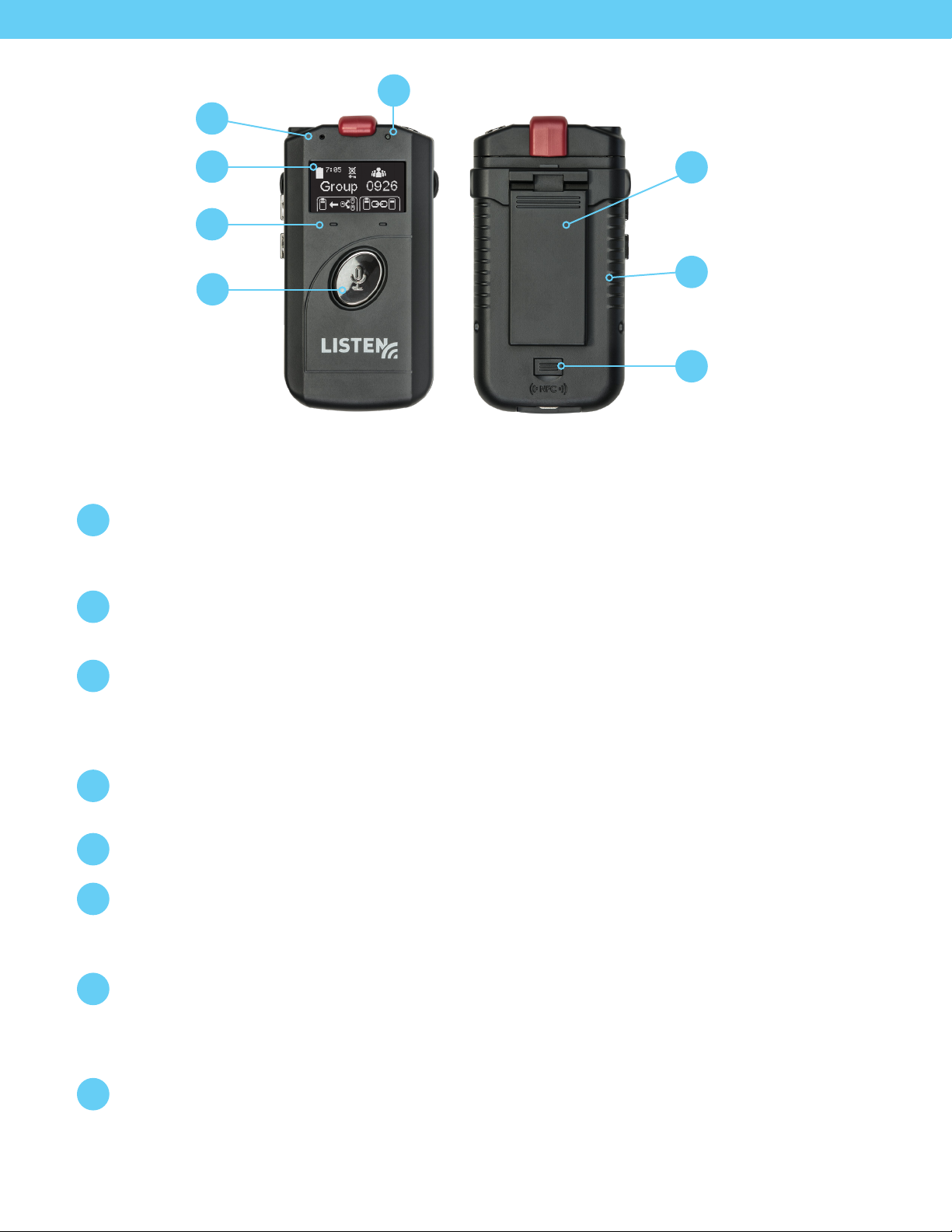
LK-1 LISTENTALK TRANSCEIVER QUICK REFERENCE
Internal Microphone
1
Internal microphone may be used by a Participant. For best results, a Leader should use an
external microphone-equipped headset. Visit www.listentech.com/assistive-listening/listentalk/
to choose from a wide range of headsets and other accessories.
Graphic Display
2
Displays context-sensitive information such as Group Name/Number, Charging Status,
Battery Life, Prole Mode, Soft Button Menus, and Volume Level.
Removable
6
Belt/Lanyard Clip
Rechargeable Battery
7
(or Alkaline)
Neareld Antenna
8
(Under Door)
Soft Buttons
3
Leader: Left Soft Button scrolls through System Talkback Modes (O Mode, Leader Mode
or Group Mode – See Page 24. Right Soft Button initiates pairing. Both buttons operate for
Transceiver programming (see Page 26).
Participant: Soft Buttons are disabled except during Transceiver programming (see Page 26).
Talk Button & Menu Exit
4
Leader: Press Talk Button to toggle between Talk and Mute.
Participant: Press and hold Talk Button to talk; release to mute.
Light Sensor
5
Automatically brightens or dims the Graphic Display based on ambient light conditions.
Removable Belt/Lanyard Clip
6
To use the Lanyard, snap its metal ring into and up in the slot at the top of the Belt Clip. Then,
adjust the Lanyard to a comfortable length and slip it over the user’s head. Alternately, simply slip
the Belt Clip over a user’s belt.
Rechargeable Battery
7
Charge ListenTALKs in Docking Station or connect a USB charger to the Micro USB port. Access
the battery compartment by depressing the button on the battery door. Alkaline batteries (not
rechargeable) may be used by installing the optional Alkaline Battery Compartment and three AAA
size alkaline batteries.
Neareld Antenna
8
Allows a Leader to Pair with Sub-Leaders or Participants to form a Group as described on Page 22.
7
Page 8
3.5mm Headset/
Microphone Port
9
14
13
Leader Clip
Status LED
12
Volume Control &
Menu Navigation
Micro USB (for
Battery Charging
& Conguration)
10
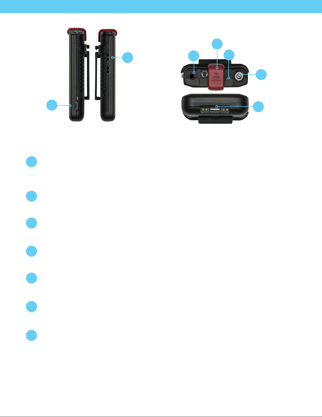
LK-1 LISTENTALK TRANSCEIVER QUICK REFERENCE
Volume Control & Menu Navigation
9
Operation: Controls Headset volume.
Programming: Navigates menus shown in the Graphic Display.
Micro USB
10
Connect Micro USB to a standard USB charger to charge the ListenTALK. Connect to a Windows
computer to program the ListenTALK using the ListenTALK Software Suite.
Power Button & Status Screen
11
Press and hold for one second to power on the ListenTALK and display the Status Screen. Press and
hold for three seconds to power o. Press momentarily to display the Status Screen during use.
Power Button
11
& Menu Enter
Bottom: Charger
Contacts
15
(for Docking Station)
Status LED
12
Status LED will ash during charging and turn solid when ListenTALK is fully charged.
Leader or Sub-Leader Status LED turns red to indicate Mute after pressing Talk Button.
Leader Clip
13
Snap a Leader Clip onto a Transceiver to create a Leader or Sub-Leader. Omit from Participant
Transceiver.
3.5mm Headset/Microphone Port
14
Use a headset such as those available at www.listentech.com/assistive-listening/listentalk/transceiverheadsets/. Note that ListenTALK Transceivers also accept standard smart phone headsets/earbuds.
Charger Contacts
15
Allow ListenTALKs to charge automatically when placed in the Docking Station. Also allow
communication with a Windows computer equipped with the ListenTALK Software Suite.
8
Page 9
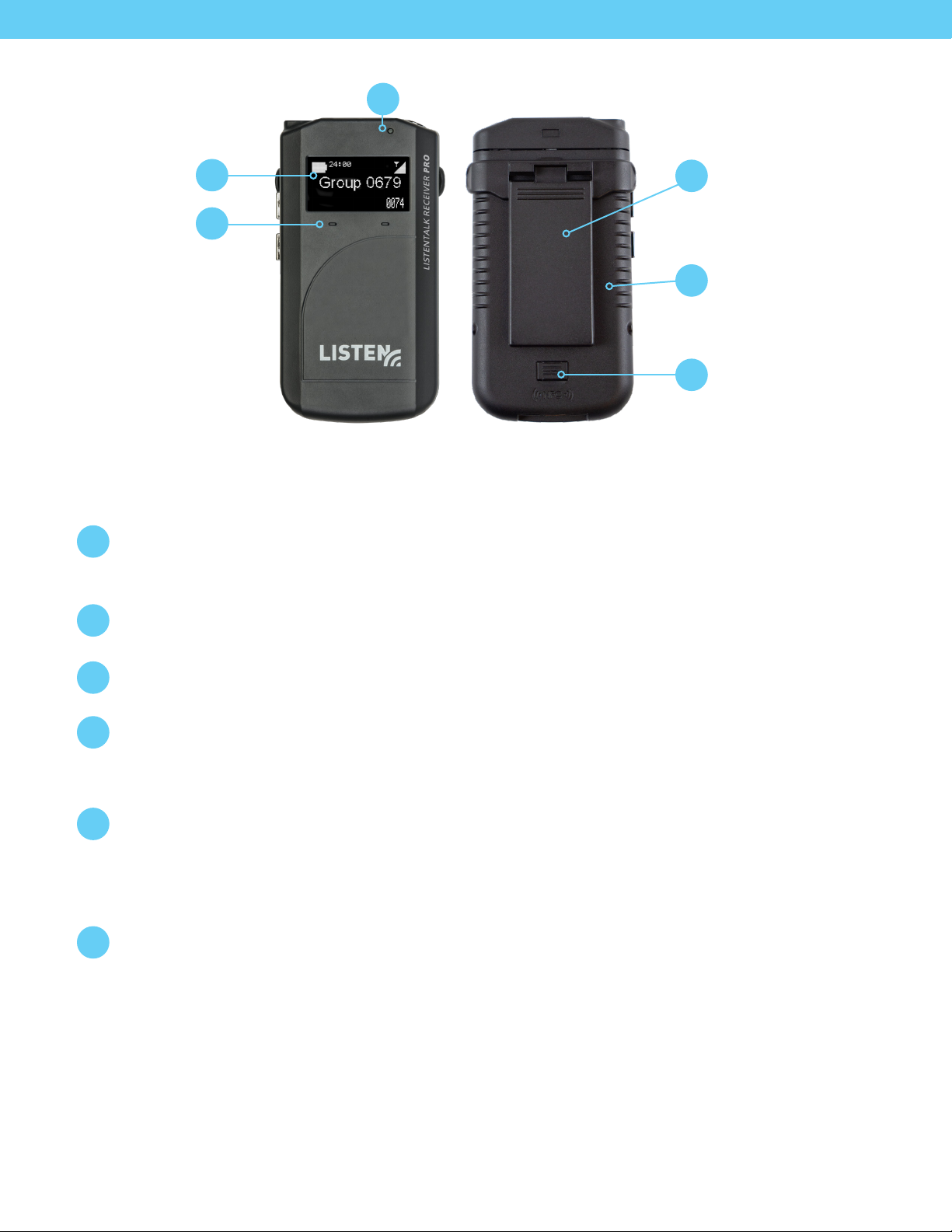
3
Light Sensor
Graphic Display
Soft Buttons
1
2
LKR-11 LISTENTALK RECEIVER PRO QUICK REFERENCE
Graphic Display
1
Displays context-sensitive information such as Group Name/Number, Charging Status,
Battery Life, Soft Button Menus, and Volume Level.
Soft Buttons
2
Participant: Soft Buttons are disabled except during Transceiver programming (see Page 26).
Removable
4
Belt/Lanyard Clip
Rechargeable Battery
5
(or Alkaline)
Neareld Antenna
6
(Under Door)
Light Sensor
3
Automatically brightens or dims the Graphic Display based on ambient light conditions.
Removable Belt/Lanyard Clip
4
To use the Lanyard, snap its metal ring into and up in the slot at the top of the Belt Clip.
Then, adjust the Lanyard to a comfortable length and slip it over the user’s head.
Alternately, simply slip the Belt Clip over a user’s belt.
Rechargeable Battery
5
Charge ListenTALKs in Docking Station or connect a USB charger to the Micro USB port.
Access the battery compartment by depressing the button on the battery door. Alkaline batteries
(not rechargeable) may be used by installing the optional Alkaline Battery Compartment and
three AAA size alkaline batteries.
Neareld Antenna
6
Allows a Leader to Pair with Sub-Leaders or Participants to form a Group as described on Page 22.
9
Page 10
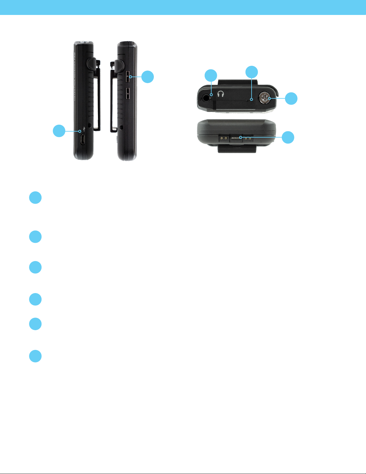
3.5mm
Headphone
Output
Status LED
7
11
10
Volume Control &
Menu Navigation
Micro USB (for
Battery Charging
& Conguration)
8
LKR-11 LISTENTALK RECEIVER PRO QUICK REFERENCE
Volume Control & Menu Navigation
7
Operation: Controls Headset volume.
Programming: Navigates menus shown in the Graphic Display.
Micro USB
8
Connect Micro USB to a standard USB charger to charge the ListenTALK. Connect to a Windows
computer to program the ListenTALK using the ListenTALK Software Suite.
Power Button
9
& Menu Enter
Bottom: Charger
Contacts
12
(for Docking
Station)
Power Button & Status Screen
9
Press and hold for one second to power on the ListenTALK and display the Status Screen. Press and
hold for three seconds to power o. Press momentarily to display the Status Screen during use.
Status LED
10
Status LED will ash during charging and turn solid when ListenTALK is fully charged.
3.5mm Headphone Output
11
Use a ear speaker/headphone such as those available at
https://www.listentech.com/assistive-listening/listentalk/earphones-neckloop-lanyards/
Charger Contacts
12
ListenTALK units charge automatically when placed in the Docking Station. Also allows
communication with a Windows computer equipped with the ListenTALK Software Suite.
10
Page 11

LKR-12 LISTENTALK RECEIVER BASIC QUICK REFERENCE
Removable Belt/Lanyard Clip
1
To use the Lanyard, snap its metal ring into and up in the slot at the top of the Belt Clip.
Then, adjust the Lanyard to a comfortable length and slip it over the user’s head.
Alternately, simply slip the Belt Clip over a user’s belt.
Removable
1
Belt/Lanyard Clip
Rechargeable Battery
2
(or Alkaline)
Rechargeable Battery
2
Charge ListenTALKs in Docking Station or connect a USB charger to the Micro USB port.
Access the battery compartment by depressing the button on the battery door.
Alkaline batteries (not rechargeable) may be used by installing the optional Alkaline
Battery Compartment and three AAA size alkaline batteries.
11
Page 12

3.5 mm
Headphone
Output
Status LED
7
6
3
Volume
Control
Micro USB (for
Battery Charging
& Conguration)
4
5
Bottom: Charger
Contacts
8
(for Docking Station)
LKR-12 LISTENTALK RECEIVER BASIC QUICK REFERENCE CONTINUED
Volume Control
3
Operation: Controls ear speaker/headphone volume.
Micro USB
4
Connect Micro USB to a standard USB charger to charge the ListenTALK. Connect to a Windows
computer to program the ListenTALK using the ListenTALK Software Suite.
Power Button
5
Press and hold for one second to power on the LKR-12. Press and hold for three seconds to power o.
Press momentarily to display the Status LED information during use.
Power Button
Status LED
6
Status LED will ash the white LED during charging and turn solid when ListenTALK is fully charged.
While unit is on momentarily press power button to activate the LED status. If unit is paired the status
LED will ash green once followed by the white LED Flashing the battery status: 1=1/4, 2=1/2, 3=3/4,
and 4=full.
Note: LKR-12 Green LED will continue ashing if receiver is not paired to a group or the Leader
unit is not turned on.
3.5mm Ear Speaker/Headphone
7
Use a ear speaker/headphone such as those available at
https://www.listentech.com/assistive-listening/listentalk/earphones-neckloop-lanyards/
Charger Contacts
8
Allow ListenTALKs to charge automatically when placed in the Docking Station. Also allow
communication with a Windows computer equipped with the ListenTALK Software Suite.
12
Page 13

Leader Clip StorageLeader Pocket (Red)
5
6
Pairing Button
Pairing Indicator
Status Indicator
Status Button
1
2
3
4
Participant Pockets
7
LISTENTALK DOCKING STATION TRAY QUICK REFERENCE
Pairing Button
1
Create a ListenTALK Group by inserting LK-1 Transceiver into Leader pocket (red) and other ListenTALK
units into Participant Pockets, and then momentarily pressing the Docking Station Pairing Button.
Note: Momentarily pressing the Docking Station Pairing Button uses the Leader’s existing Pairing Key.
To create a new Pairing Key, press and hold the Pairing Button for ve seconds (also see Page 22).
This will generate a new group and eliminate previously paired ListenTALK units from the group.
Pairing Indicator
2
Pairing Indicator will ash during pairing, then turn solid momentarily and nally extinguish when the
pairing process is completed successfully. The Pairing and Status Indicators will turn solid together
and then extinguish during New Pair Key generation (see Page 28).
Status Indicator
3
Status Indicator lights during Status Button activation and during new pair key generation.
Status Button
4
Press and hold the Status Button to illuminate the ListenTALK Graphic Displays for
Group identication and individual ListenTALK information.
Leader Pocket (Red)
5
Used for charging, pairing and programming.
Leader Clip Storage
6
Snap unused Leader Clips onto these storage tabs.
Participant Pockets
7
Used for charging, pairing and programming.
13
Page 14

8
Handles
USB Port Power Connector
9 10
Wall Mounting Slots
12
11
Intelligent
Cable
Management
Unit Mounts
(LA-382)
LISTENTALK DOCKING STATION TRAY QUICK REFERENCE
Handles
8
Handles for holding the Docking Station Tray.
USB Port
9
Connect to Windows computer to program, pair and manage inventory of ListenTALK
units using the ListenTALK Software Suite.
Power Connector
10
Connect the Power Supply to this Power Connector and the Power Cord to any standard
AC outlet (100/240 VAC, 50/60 Hz).
Intelligent Cable Management Unit Mounts (LA-382)
11
The Optional Docking Station Intelligent Cable Management Unit fastens to these holes.
Wall-Mounting Slots
12
Mount two screws with ¼” heads 6-inches apart on a wall. Slip Docking Station 16
onto screw heads.
14
Page 15

LK-1 LISTENTALK TRANSCEIVER SPECIFICATIONS*
Physical
Dimensions (H x W x D) with Belt Clip 10 x 5.4 x 2.4 cm (3.93 x 2.13 x 0.93 in.)
Dimensions (H x W x D) less Belt Clip 10 x 5.4 x 1.6 cm (3.93 x 2.13 x 0.63 in.)
Weight 79 g (2.79 oz.)
Ship Weight 206 g (7.20 oz.) with 454 g (1.0 lbs.) minimum
Enclosure material PC ABS Plastic
Indicators
User Controls Volume up, Volume Down, Talk, Power/Status, Talk Modes, Pairing
Programming Via software and USB port on Transceiver or via software and USB port on Docking Station
Connections
Display - 64 x 128 OLED, Variable brightness LED – RED/White multifunction
(Mute, Charge Status)
Headset – 3.5mm TRRS, CTIA compliant
USB – Micro USB, Control and Charging
Charger- 4 Contact, Control and Charging
Audio
Microphone Input
Compatibility Electret, external bias
Bias 3 volt, 2 mA Current Maximum
Sensitivity requirement -28 to - 50 dBV/Pa
Internal Microphone
Switching Auto detect on jack insertion or Manual
Maximum input level 109 dB SPL
Gain Adjustable, 30 dB range
Headset/Microphone Port
Purpose
Connector
Nominal Input Level for Line Source -10dBu (0.24 volts)
Speaker load 16 - 32 ohm load
Max output power 67 mW, 16-ohm load, Threshold of Clipping
Sidetone Adjustable
System
Frequency Response 40 Hz to 15 kHz +/- 3dB, 22kHz low pass lter
SNR 70 dB, A- weighted, Threshold of Clipping
THD 0.5% @ 1kHz, 22kHz low pass enabled
Accepts Listen Technologies Headsets or standard smart-phone headsets.
Can be used as a Mic/Line input (See “Mic Select” Menu Choices on Page 26)
Tip Headset Left +
First Ring Headset Right +
Second Ring Common/Ground/Sleeve Mic/Line Input +
15
Page 16

LK-1 LISTENTALK TRANSCEIVER SPECIFICATIONS CONTINUED
Radio
Operating Frequency
Average Power
Typical Range
Modulation
Security
North America – 1920 to 1930 MHz
Europe – 1880 to 1900 MHz
North America – 4 mW
Europe – 10 mW
North America – Indoor 100 m, Outdoor 200 m, depending upon conditions
Europe – Indoor 150 m, Outdoor 300 m, depending upon conditions
GFSK – FHSS
TDD/TDMA/DCA
Subscription – 40 bit (Pin Free)
Authentication – 32 bit
Encryption – 64 bit
Power & Battery Management
Battery type
Typical operate time
Typical charge time 4 Hours
Lithium – ion, rechargeable non-proprietary removable, 1200 mAh
Optional – 3 AAA Battery Compartment
Li-ion – Participant Mode – 12 Hours
AAA – Participant Mode – 7 Hours
Li-ion – Leader Mode – 7 hours
AAA – Leader Mode – 4 hours
Power down on loss of signal
Power save modes
Power down on disconnection of headset (1 min)
Power down on charging
Environmental
Temperature - Operation -10° C (14° F) to 40° C (104° F)
Temperature - Storage -20° C (-4° F) to 50° C (122° F)
Relative Humidity 0 to 95% relative humidity, non-condensing
Compliance
Standards Pending (FCC part 15, ICS-03, CE, RCM, RoHS, WEEE)
* Specications subject to change without notice.
16
Page 17

LKR-11 LISTENTALK RECEIVER PRO SPECIFICATIONS*
Physical
Dimensions (H x W x D) with Belt Clip 10 x 5.4 x 2.4 cm (3.93 x 2.13 x 0.93 in.)
Dimensions (H x W x D) less Belt Clip 10 x 5.4 x 1.6 cm (3.93 x 2.13 x 0.63 in.)
Weight 79 g (2.79 oz.)
Ship Weight 206 g (7.20 oz.) with 454 g (1.0 lbs.) minimum
Enclosure material PC ABS Plastic
Indicators
User Controls Volume up, Volume Down, Power/Status, Pairing
Programming Via software and USB port on Transceiver or via software and USB port on Docking Station
Connections
Display - 64 x 128 OLED, Variable brightness LED – RED/White multifunction
(Mute, Charge Status)
Headset – 3.5mm TRRS, CTIA complaint
USB – Micro USB, Control and Charging
Charger- 4 Contact, Control and Charging
Audio
Headphone Output
Speaker load 16 - 32 ohm load
Max output power 67 mW, 16-ohm load, Threshold of Clipping
Purpose Accepts standard earspeaker/headphones
Tip Headset Left +
Connector
System
Frequency Response 40 Hz to 15 kHz +/- 3dB, 22kHz low pass lter
First Ring Headset Right +
Second Ring Common/Ground/-
Sleeve Not Connected
SNR 70 dB, A- weighted, Threshold of Clipping
THD 0.5% @ 1kHz, 22kHz low pass enabled
17
Page 18

LKR-11 LISTENTALK RECEIVER PRO SPECIFICATIONS CONTINUED
Radio
Operating Frequency
Average Power
Typical Range
Modulation
Security
North America – 1920 to 1930 MHz
Europe – 1880 to 1900 MHz
North America – 4 mW
Europe – 10 mW
North America – Indoor 100 m, Outdoor 200 m, depending upon conditions
Europe – Indoor 150 m, Outdoor 300 m, depending upon conditions
GFSK – FHSS
TDD/TDMA/DCA
Subscription – 40 bit (Pin Free)
Authentication – 32 bit
Encryption – 64 bit
Power & Battery Management
Battery type
Typical operate time
Typical charge time 4 Hours
Power save modes
Lithium – ion, rechargeable non-proprietary removable, 1200 mAh
Optional – 3 AAA Battery Compartment
Li-ion – Participant Mode – 12 Hours
AAA – Participant Mode – 7 Hours
Power down on loss of signal
Power down on disconnection of headphone (1 min)
Power down on charging
Environmental
Temperature - Operation -10° C (14° F) to 40° C (104° F)
Temperature - Storage -20° C (-4° F) to 50° C (122° F)
Relative Humidity 0 to 95% relative humidity, non-condensing
Compliance
Standards Pending (FCC part 15, ICS-03, CE, RCM, RoHS, WEEE)
* Specications subject to change without notice.
18
Page 19

LKR-12 LISTENTALK RECEIVER BASIC SPECIFICATIONS*
Physical
Dimensions (H x W x D) with Belt Clip 10 x 5.4 x 2.4 cm (3.93 x 2.13 x 0.93 in.)
Dimensions (H x W x D) less Belt Clip 10 x 5.4 x 1.6 cm (3.93 x 2.13 x 0.63 in.)
Weight 79 g (2.79 oz.)
Ship Weight 206 g (7.20 oz.) with 454 g (1.0 lbs.) minimum
Enclosure material PC ABS Plastic
Indicators Variable brightness LED – Green/White multifunction, Charge Status, Battery Status
User Controls Volume up, Volume Down, Power/Status
Programming Via software and USB port on Transceiver or via software and USB port on Docking Station
Headset – 3.5mm TRRS, CTIA complaint
Connections
Audio
Headphone Output
USB – Micro USB, Control and Charging
Charger- 4 Contact, Control and Charging
Speaker load 16 - 32 ohm load
Max output power 67 mW, 16-ohm load, Threshold of Clipping
Purpose Accepts standard earspeaker/headphones
Tip Headset Left +
Connector
System
Frequency Response 40 Hz to 15 kHz +/- 3dB, 22kHz low pass lter
SNR 70 dB, A- weighted, Threshold of Clipping
THD 0.5% @ 1kHz, 22kHz low pass enabled
First Ring Headset Right +
Second Ring Common/Ground/-
Sleeve Not Connected
19
Page 20

LKR-12 LISTENTALK RECEIVER BASIC SPECIFICATIONS CONTINUED
Radio
Operating Frequency
Average Power
Typical Range
Modulation
Security
North America – 1920 to 1930 MHz
Europe – 1880 to 1900 MHz
North America – 4 mW
Europe – 10 mW
North America – Indoor 100 m, Outdoor 200 m, depending upon conditions
Europe – Indoor 150 m, Outdoor 300 m, depending upon conditions
GFSK – FHSS
TDD/TDMA/DCA
Subscription – 40 bit (Pin Free)
Authentication – 32 bit
Encryption – 64 bit
Power & Battery Management
Battery type
Typical operate time
Typical charge time 4 Hours
Power save modes
Lithium – ion, rechargeable non-proprietary removable, 1200 mAh
Optional – 3 AAA Battery Compartment
Li-ion – Participant Mode – 12 Hours
AAA – Participant Mode – 7 Hours
Power down on loss of signal
Power down on disconnection of headphone (1 min)
Power down on charging
Environmental
Temperature - Operation -10° C (14° F) to 40° C (104° F)
Temperature - Storage -20° C (-4° F) to 50° C (122° F)
Relative Humidity 0 to 95% relative humidity, non-condensing
Compliance
Standards Pending (FCC part 15, ICS-03, CE, RCM, RoHS, WEEE)
* Specications subject to change without notice.
20
Page 21

LISTENTALK DOCKING STATION CASE 16 SPECIFICATIONS*
Physical
Case Color Gray & Chrome
Tray Color Black, Chrome Buttons, Red Leader Pocket
Dimensions (H x W x D) 190 x 350 x 465 mm (7.48 x 13.78 x 18.31 in.)
Unit Capacity 16 Units
Unit Weight 5.13 kg (11.3 lbs.)
Ship Weight 5.95 kg (13.1 lbs.)
Power
Power Supply Input 100-240 VAC, 50-60 Hz
Power Supply Output 12 VDC, 5.0 A, 60 W
Power Supply Connector 5.5 mm (0.22 in.) OD x 2.3 mm (.09 in.) ID, barrel type
Power Cord 182.9 cm (72 in.) Input Power Cord, 109.3 cm (43 in.) Output Cord
Interconnections
Connection/s USB type B
Power
Compliance
Power Supply UL, CE, RCM, RoHS
* Specications subject to change without notice.
LISTENTALK SYSTEM SETUP
Mount and Connect the Docking Station
ListenTALK Transceivers may be operated with or without a Docking Station. If your
system does not have a Docking Station, please proceed to “Prepare and Charge Each
ListenTALK Transceiver” (next). Mount the Docking Station on a at surface. Connect
the Power Supply to the Docking Station and to any standard AC outlet (100/240 VAC,
50/60 Hz). To program the Docking Station and its units via computer (USB) install the
ListenTALK Software Suite (see Page 29).
21
Page 22

LISTENTALK SYSTEM SETUP CONTINUED
Prepare and Charge the ListenTALK Units
Remove the protective screen cover and clear plastic battery isolation tab from each unit.
Charge units in the Docking Station or connect each unit’s Micro USB to a USB charger.
When 100% charged, a unit’s Status LED is solid. Alternately, insert the optional Alkaline
Battery Compartment and three AAA size alkaline batteries.
Create a ListenTALK Leader
Each LK-1 ListenTALK Transceiver can be a Leader or a Participant. The default mode is
Participant. To create a Leader, turn on any Transceiver and place a red Leader Clip on
the Transceiver. To create a Sub-Leader, place a Leader Clip on a LK-1 unit and pair to
the Leader.
Create a ListenTALK Group by Pairing ListenTALK Units
A ListenTALK Group consists of at least one Leader and an unlimited number of
Participants and Sub-Leaders (Sub-Leaders are optional). Create a ListenTALK Group
by Pairing a Leader with Participants and Sub-Leaders.
Pairing With a Docking Station
Pairing
Button
Place the Leader into the red Docking Station pocket. Place Participant and Sub-Leader
units into the black Docking Station pockets (see diagrams on Page 13). Momentarily press
the Pairing Button on the Docking Station. Pairing Indicator will ash during pairing, then
turn solid momentarily and nally extinguish when the pairing process is completed. To
pair more than 15 Participants and Sub-Leaders, repeat the process using the same Leader.
Note: If the pair button is held down for ve seconds the leader will generate a new pair
key and eliminate previously paired units from the group.
Pairing Without a Docking Station – Near-Field Communication Method
(LK-1 and LKR-11 Only)
Press and hold the Leader’s Right Soft Button to initiate Pairing Mode. Then, Pair
Participant and Sub-Leader units to the Leader by touching the back of the Leader to
the back of each Participant and Sub-Leader. Upon successful pairing, the Participant or
Sub-Leader will beep and display a link symbol on its Graphic Display. Press and hold the
Leader’s Right Soft Button again to exit Pairing Mode.
Create Additional ListenTALK Groups
An unlimited number of ListenTALK Groups may be created by repeating these steps.
Up to 10 groups may be operated simultaneously in one area.
Adding Participants to an Existing Group
With a Docking Station, simply place the existing Leader in leader pocket and new
Participant or Sub-Leader units into the Docking Station and press the Pairing Button
momentarily. To add Participants without a Docking station, place the Leader into Pairing
Mode and touch the back of the Leader to each new Participant or Sub-Leader.
(not available with LKR-12)
22
Connect Ear Speakers or Headsets
Connect headsets, ear speakers, or headphones to each unit. Participants may use the
LK-1 ListenTALK Transceiver’s built-in microphone. Leaders and Sub-Leaders should use
a microphone-equipped headset in noisy environments.
Page 23

LISTENTALK UNITS – GENERAL OPERATION
General Operation
Belt Clip and Lanyard
To use the Lanyard, snap its metal ring in and up in the slot at the top of the Belt Clip. Then, adjust the
Lanyard to a comfortable length and slip it over the user’s head. Alternately, simply slide the Belt Clip
over a user’s belt.
Power Button
Press and hold the Power Button for one second to turn the unit on. Press and hold the Power Button for
three seconds to turn it o. While a unit is powered on, a momentary Power Button press will display the
unit’s status for three seconds.
Volume Buttons
Press the Volume Up or Volume Down button to increase or decrease the volume.
LK-1 or LKR-11 Display and Status
The Display will extinguish automatically after a few seconds. Press the Power Button momentarily to
check unit Status. Press any button (i.e. Volume Up/Down) to activate the Display for that function.
Function buttons operate normally even when the Display is o.
Battery Status, Charging and Battery Replacement
The Status LED will ash slowly when the unit needs to be charged. Rechargeable ListenTALK units may be
charged in the Docking Station. To charge an individual unit, connect a USB charger to its Micro USB port. To
replace batteries on units equipped with the optional Alkaline Battery Compartment, depress the button on
the battery door to access the Battery Compartment. Insert three AAA size alkaline batteries.
Internal Microphone (LK-1 Only)
In quiet environments, both Leader and Participants may use the Transceiver’s Internal Microphone.
Microphone-equipped headsets are best for noisy environments visit
www.listentech.com/assistive-listening/listentalk/transceiver-headsets/
Participant Buttons (LK-1 Only)
Press and hold the Talk Button to speak. Release to mute. Participant can speak to the entire Group or only to
the Leader depending on the Talkback Mode set by the Leader (see Page 24). The Participant Talk Button does
not function when the Leader chooses “O” mode. Only one Participant can speak at a time. Soft Buttons are
disabled on Participant Transceivers.
Leader Buttons (LK-1 Only)
Press and release the Talk Button to toggle between Talk and Mute. It is not necessary to hold down the
Leader’s Talk Button. The Leader congures ListenTALK Talkback Modes as described on Page 24. The Leader
also controls Group Pairing and passes the Group Name and Pair Key to Sub-Leaders and Participants.
Sub-Leader Buttons (LK-1 Only)
The Sub-Leader’s Talk Button operates like that on a Leader. A Sub-Leader can Pair new Sub-Leaders and
Participants making them members of a Group. In so doing, the Sub-Leader passes on the Group Name and
Pair Key from the Leader.
23
Page 24

Operation with Leader and Sub-Leader
ListenTALK Groups have one Group Leader and an unlimited number of Sub-Leaders and Participants.
A single Sub-Leader is useful for classes with dual instructors or tour groups led by more than one
person. A Group with one Leader and multiple Sub-Leaders is a versatile wireless intercom for event
production, sporting activities and training sessions and it can facilitate workgroup collaboration in
warehouses, manufacturing environments or construction sites. Sub-Leaders can Pair with new Sub-
Leaders or Participants, making them members of a Group and passing the Group name and Pair Key
from the Leader. Also see Applications on Page 29.
LISTENTALK SYSTEM TALKBACK MODES
The ListenTALK system allows the Leader to control the ow of conversation based upon the individual needs
of the group. Press and release the Leader’s Left Soft Button repeatedly to toggle among the three Talkback
Modes which are O/Listen-only Mode, Leader/Respond Mode and Group/Discuss Mode.
These modes function dierently based on the Leader’s setting of “Sub-Leader Always Broadcast”
(Default is enabled). The setting of Sub-Leader Always Broadcast mode can only be disabled via
ListenTALK Software Suite.
The Leader’s Graphic Display indicates Talkback Mode (see below). During Talkback Mode only one
Participant or Sub-Leader can speak at a time with the Leader.
O / Listen-only Mode – Leader’s Display has an X but No Arrows
Sub-Leader Always Broadcast Enabled – Leader and Sub-Leaders communicate with
one another and broadcast to Participants but Participants cannot respond.
Sub-Leader Always Broadcast Disabled – Leader can broadcast to Participants and
Sub-Leaders but participants and Sub-Leaders cannot respond.
Leader / Respond Mode – Leader’s Display has Left Arrow
Sub-Leader Always Broadcast Enabled - Leader and Sub-Leaders communicate with
one another and broadcast to Participants but Participants can only pose a question
to the Leader. Sub-Leaders must release the Talkback channel to allow Participants
to pose a question.
Sub-Leader Always Broadcast Disabled – Leader can broadcast to Participants and
Sub-Leaders but Participants and Sub-Leaders can only pose a question to the
Leader. Sub-Leaders must release the Talkback channel to allow Participants to
pose a question.
Group / Discuss Mode – Leader’s Display has Left and Right Arrows
Participants and Sub-Leaders can listen and respond to the Leader and other Group
members. Group / Discuss Mode functions the same regardless of the setting of
“Sub-Leader Always Broadcast”.
24
Page 25

LISTENTALK SECURITY
Conversations within a ListenTALK Group are encrypted by a unique Pair Key which separates Groups from
one another and ensures secure conversations within each Group. The Pair Key is generated by the Group’s
Leader and shared with each Sub-Leader and Participant. When Sub-Leaders add new Transceivers to a Group,
they pass the Leader’s Pair key to these new group members.
ListenTALK Pair Key security may be congured with the ListenTALK Software Suite or through the
Leader’s New Pair Key menu choices as described next.
Never – Normal Security (Default)
By this (default) choice the Pair Key never changes within a Group. This enables secure communication
within a Group while allowing unrestricted Group expansion and is a good choice for venues like museums
where the number of Participants may vary from tour to tour.
8 Hours, 4 Hours or 1 Hour – High Security
By this choice, the existing Pair Key is maintained when expanding a Group within the chosen time window.
After the time window expires, the Leader will generate a new Pair Key when it Pairs with a Sub-Leader or
Participant making them part of a new Group. This enables expansion of an existing Group but only
within the chosen time window.
Always – Highest Security
By this choice, the Leader will always generate a new Pair Key when it Pairs with a Sub-Leader or
Participant making them part of a new Group. This disables the expansion of an existing group
and is a good choice for high-security venues.
Resetting a Group’s Pair Key
It is possible to reset a Group’s Pair Key without changing the Group Name. This may be useful when a unit is
misplaced and you want to exclude that unit from the Group thereby preventing it from listening to or taking
part in conversations.
To reset the Pair Key for a ListenTALK Group, place the Leader, Sub-Leader(s) and Participants into their
respective Docking Station pockets. Then, press and hold the Docking Station Pairing Button for ve seconds.
The Paring and Status Indicators will ash momentarily and then turn solid indicating success.
The ListenTALK Software Suite can also implement this process.
To reset the Pair Key for a ListenTALK Group without a Docking Station, set the Leader’s New Pair Key menu
choice to “Always”. Then, repeat the Near Field Communication pairing operation for all units in a Group.
Note that the Docking Station and Software Suite can force a New Pair Key without regard to the
Leader’s New Pair Key menu choice.
LISTENTALK UNIT PROGRAMMING
ListenTALK units may be programmed by placing them in the Docking Station and connecting the Docking
Station USB Port to a Windows computer equipped with the ListenTALK Software Suite. An individual
ListenTALK unit may be programmed by connecting its Micro USB to the USB port on a Windows computer
equipped with the ListenTALK Software Suite. An individual ListenTALK unit may be programmed by pressing
specic buttons on the unit while monitoring its Graphic Display. Programming choices are described in the
following topic.
25
Page 26

Programming an Individual ListenTALK Unit Without a Computer
Accessing the ListenTALK Transceiver Menu
Turn on the unit. Then, simultaneously press and hold the Power Button and Volume
Down Button for about three seconds to access the Programming Menu.
The Display will say “Main Menu” at the top. The unit will automatically exit
the Menu after 20 seconds of inactivity.
Navigating the Menu
Scroll through Menu Items using the Volume Up and Down Buttons. The Display shows the current
Menu Item in large type. The previous and next Menu Items are displayed in smaller type above
and below the current Menu Item.
Press and momentarily hold the Right Soft Button to access a Menu Item. Then, scroll through options
for this Menu Item using the Volume Up and Down buttons. To choose an option, press and momentarily
hold the Right Soft Button again. The Menu Item will display a check mark to conrm your choice.
Then, press and momentarily hold the Left Soft Button to exit this Menu Item.
Exiting the ListenTALK Unit Menu
To exit the Transceiver menu and save your choices, press the Left Soft Button twice.
The Display will show “Updated” to conrm that your choices have been saved.
Unit Menu Choices
Soft Buttons (LK-1 Only)
Unlock ALL (default): Unlocks and allows Leader access to soft button functions.
Lock ALL: Locks leader access to soft button functions.
Lock TB Only: Locks Talkback soft button and unlocks Pair soft button.
Lock Pair Only: Locks Pair soft button and unlocks Talkback soft button.
Mic/Line Select (LK-1 Only)
Auto (default): Automatically selects an external mic, if present, or the ListenTALK’s internal mic if
no external mic is detected.
Internal: Forces use of the ListenTALK’s internal microphone.
External: Forces use of an external microphone.
Line: Allows use of an external, -10dBu line-level source.
Mic/Line Gain (LK-1 Only)
Auto (default): Appropriate for the Transceiver’s internal microphone and most external microphones.
Numeric: To manually adjust the gain for an external microphone or line-level source, scroll up or down
for up to ±12dB of increase/decrease in 3dB increments.
Brightness
Auto (default): Uses the ListenTALK’s Light Sensor to adjust Display brightness.
Bright or Dim: Permanently adjusts the display brightness.
O: Turns the display o during normal use. (Volume Up & Down,
Talk Button remain functional).
26
Page 27

Auto Power
On (default): The unit will automatically turn o and charge when it is returned to the Docking Station
and automatically turn on when it is removed from the Docking Station.
O: Control the unit’s on/o status manually.
Auto O
30 Minutes (default): Turns the unit o after 30 minutes of inactivity (no link to Leader).
20 Minutes or 10 Minutes: Turns the unit o after 20 or 10 minutes of inactivity.
O: Disables the Auto O function.
Jacksense
On (default): Turns on the unit when a headset is connected to the Headset/Microphone Port;
turns o the unit when the headset is disconnected.
O: Control the unit’s on/o status manually.
Sidetone (LK-1 Only)
Normal (default): A talker hears their own voice at a normal level in their own headset.
Quiet or Loud: Decreases or increases the level of a talker’s voice in their own headset.
New Pair Key (LK-1 Only)
This menu choice – which only functions on a Leader - controls ListenTALK New Pair Key security.
Please see ListenTALK Security on Page 25 for a discussion of this menu choice.
Mode Select (LK-1 Only)
Use Leader Clip (default): You must insert a Leader Clip to convert a Transceiver into a Leader.
Force Leader: Converts a Transceiver into a Leader without a Leader Clip.
Language
English (default): The default language for the Menus is English.
Espanol, Duetsch, Français, Italiano: Presents Menus in Spanish, German, French or Italian.
Reset Device
No (default): Maintains existing menu choices, Group name and Pair Key.
Yes: To reset the ListenTALK to all factory default settings, choose Yes.
About
The About menu displays information about the individual unit.
Model • Serial Number • Firmware Version • Region Information • Compliance labeling
Default Volume (Software Programming Only, LK-1 Only)
35% (Default)
Numeric: Each time ListenTALK is powered on the headset volume level is set to 35% which is the default
level. To change the default volume level setting adjust the software slider to the desired level. The slider can
be adjusted in 5% increments from 5% to 100%.
Leader Mute Disabled (Software Programming Only, LK-1 Leader Only)
(Default) With the box unchecked this feature is disabled, and the unit’s Talk Button will mute/unmute the
Leader’s audio as in normal operation.
With this box checked this feature is enabled and the units Talk Button will be disabled. In this mode the
unit will remain in an unmuted state not allowing the Talk Button to mute the leader’s audio.
Note: When enabled and the Talk Button is pressed the unit will show the mic active/lock symbol icon
on the display.
Subleader Always Broadcast (Software Programming Only, LK-1 Only)
(Default) When this feature is enabled (checked) subleaders in the group always broadcast to the group
independent of the Leader Talkback Mode selected. This allows the Leader and Subleaders to
address the group but not allow question from the Participants in the group.
When this feature is disabled Subleaders and Participant function the same for a given Talkback Mode.
27
Page 28

LISTENTALK DOCKING STATION OPERATION (SEE PAGES 13-14)
The ListenTALK Docking Station operates as a charger and programming station and provides convenient
storage for ListenTALK units. Mount the Docking Station on a at surface. Connect the Power Supply to the
Docking Station and to any standard AC outlet (100/240 VAC, 50/60 Hz). Place ListenTALK units into the
Leader and Participant Pockets to charge and program the units.
Creating a ListenTALK Group with the Docking Station
To create a Leader, or Sub-Leader snap a red Leader Clip onto any LK-1 Transceiver. Omit the Leader Clip
from Participant ListenTALKs. Place the Leader in the Docking Station’s red Leader Pocket. Place Sub-Leader(s)
and Participants in the Docking Station’s black Participant Pockets.
To create a Group, Pair the Leader with Sub-Leader(s) and Participants by pressing the Pairing Button
momentarily on the Docking Station. The Pairing Indicator will ash during pairing, then turn solid and
nally extinguish when the pairing process is completed.
Resetting a Group’s Pair Key with the Docking Station
To reset the Pair Key for a ListenTALK Group, place the Leader, Sub-Leader(s) and Participants into
their respective Docking Station pockets. Then, press and hold the Docking Station Pairing Button
for ve seconds. The Pairing and Status Indicators will ash momentarily and then turn
solid indicating success.
Checking ListenTALK Status with the Docking Station
Press the Docking Station Status Button. The Status Indicator will illuminate and the individual
ListenTALK Graphic Displays will show ListenTALK unit ID, Group name, Group number,
battery status, signal strength and other information.
LISTENTALK ADVANCED FEATURES
Using Multiple ListenTALK Groups
Each ListenTALK Group operates on its own communications channel. You may create an unlimited
number of ListenTALK Groups and up to ten Groups may operate without interference within a
given area. ListenTALK Groups have one Group Leader and an unlimited number of Sub-Leaders
and Participants. Communication within a Group is encrypted by a unique Pair Key making
ListenTALK an ideal choice for facilities that need secure communications for simultaneous
translation, tour-guide use and other applications. Please see “ListenTALK Security” on
Page 25 for more information.
Charging and Battery Replacement
Rechargeable ListenTALK units may be charged in the Docking Station. To charge an individual unit,
connect a USB charger to its Micro USB port.
To replace batteries on a non-rechargeable unit, depress the button on the battery door and slide the
battery door downwards. Insert three AAA size alkaline batteries.
Updating ListenTALK Firmware
ListenTALK unit rmware updates are available through the ListenTALK Software Suite.
28
Page 29

LISTENTALK SOFTWARE SUITE
The ListenTALK Software Suite allows a Windows computer to program a ListenTALK system and check
ListenTALK status. After installation, the software will automatically connect to any Docking Station or
individual Transceiver connected to the computer’s USB port.
ListenTALK Software Suite features include complete setup, inventory management, group creation and
naming. The suite includes an extensive help le.
LISTENTALK ACCESSORIES
A wide variety of accessories enable ListenTALK systems to be congured for many dierent
applications. A complete list and full description of ListenTALK accessories may be found at:
www.listentech.com/assistive-listening/listentalk/
Docking Station Case 16
The Docking Station Case has the same features as the Docking Station Tray 16 in a convenient portable form.
Chargers
For applications that do not require Docking Station programming features, Listen oers a one-port or
four-port USB charger.
Headsets
Several varieties of headsets are available allowing ListenTALK usage in quiet and noisy environments.
ListenTALK Transceivers accept third-party earphones and microphone-equipped earphones through their
3.5mm Headset/Microphone Ports. ListenTALK Transceivers include a built-in microphone which may be
used by Participants in quiet environments.
Other Accessories
Other accessories include a spare Lithium-Ion Rechargeable Transceiver Battery Pack,
a AAA Alkaline Battery Compartment and a Transceiver Protective Case.
LISTENTALK APPLICATIONS
Tour Guide System
A ListenTALK System is ideal for use as a museum, factory or other facility tour-guide system. Create a
ListenTALK Group as described on Page 22. Press and release the Leader’s Talk Button to toggle between
Talk and Mute. Press and hold a Participant Talk Button (LK-1 only) to talk to the Leader or Group as dened
by the Leader’s choice of Talkback Modes (see Page 24).
Tour Guide System with Leader and Sub-Leader
A second ListenTALK Leader, known as a Sub-Leader, is useful for two-instructor tours, classrooms or any
application where a second Leader will accompany a group and speak to all Group members. Insert a red
Leader Clip onto a Transceiver and Pair it to the Leader (see Page 22) to create a Sub-Leader. The Leader
controls the Group name, Pair Key and Talkback Modes. The Sub-Leader Talk Button toggles between Talk
and Mute modes. Sub-Leaders can Pair with new Sub-Leaders or Participants, making them members
of the Group and passing the Group name and Pair Key from the Leader.
29
Page 30

Training and Collaboration
A ListenTALK System with multiple Sub-Leaders is ideal for training in a corporate or sports setting.
Choose a noise-cancelling, microphone-equipped headset when needed for noisy environments and
set the ListenTALK System Talkback Mode as desired to restrict or enable talkback from Sub-Leaders
and Participants (see Page 24).
Simultaneous Translation
It may be desirable to create two, separate ListenTALK Groups so that Participants speaking one language
are not confused by translation into a second language. For this application, create two separate ListenTALK
Groups in a normal manner as described on Page 22. The ListenTALK Software Suite allows Groups to have
descriptive names such as “English” and “Spanish”.
Wireless Intercom
Two or more ListenTALK Transceivers may be used as a versatile wireless intercom for event production,
sporting activities and training sessions and it can facilitate workgroup collaboration in warehouses,
manufacturing environments or construction sites. Create a ListenTALK Group with one Transceiver as
Leader and the other Transceivers as Sub-Leaders to enable hands-o, full-duplex conversations.
The Talk Button on a Leader or Sub-Leader is a toggle – touch once to talk; touch again to mute. This allows
a Leader and a Sub-Leader to hold a hands-o, full-duplex conversation (both in Talk Mode). If a second
Sub-Leader presses their Talk Button, they take over the conversation and the rst Sub-Leader automatically
mutes. Multiple Sub-Leaders can hold a conversation with the Leader in this manner while other Sub-Leaders
listen. To enable this capability, the Leader must choose “Group Mode” using their Left Soft Button. Also see
“Operation with Leader and Sub-Leader” on Page 24.
LISTENTALK SYSTEM TROUBLESHOOTING
The ListenTALK Has No Power
Make sure the ListenTALK has a fully charged battery or is connected to a standard USB charger.
Make sure the Power Button on the top of the unit has been pressed to turn the unit ON. If this does
not work, make sure the battery is installed properly and/or install a replacement battery.
There is No Audio
Check that the ListenTALK is on the same Group with other Participants and the Leader. Make sure the
Volume Control is turned up to at least 25%. Conrm that the headset is plugged in all of the way.
Audio is Distorted
Verify the audio on the unit is not turned up too loud; this will cause distortion. Insure the headset
connectors are pushed all the way into the Headset/Microphone Port on top of the unit.
Try a dierent headset.
I Cannot Pick Up the Signal on My ListenTALK
Check to make sure the ListenTALK Leader and Participants are members of the same group.
I Can Pick up the Signal on the ListenTALK, but it Sounds like it’s not Tuned in.
Check the ListenTALK Leader and Participant and conrm members of the same group and
move closer to the Leader.
30
Page 31

My Battery is Not Charging (Rechargeable ListenTALK Units).
Verify the clear plastic pull tab has been removed from the ListenTALK battery door engaging the battery
connections. Make sure the battery is installed properly and that the unit is fully inserted into the Docking
Station pocket. If using a USB charger, try another USB cable. Check the charging device to verify it is plugged
in the proper power outlet and power is available at the outlet. If this does not work, install a replacement
battery.
I Want to Run the ListenTALK Unit from a USB Charger
Simply plug any standard USB charger into the Micro USB connector on the side of the ListenTALK unit.
Dock Communication Error
If a communication error occurs the Docking Station will display an error message for 5 seconds on the rst
available ListenTALK unit. The message will display an error code as well as indicate the pocket that is having the
communication error. The Docking Station will fast ash the red LED indicating an error followed by the ashing
Yellow LED indicating the error code and the pocket number.
If this happens examine the pocket in question for damaged pins, reseat the unit in the pocket and repeat the
operation that caused the error. If it continues determine if it is the unit or pocket that is causing the error by
placing the unit in another pocket and repeating the operation. For more detail or to x the issue contact Listen
Technical support.
Error 2 (Unit Removed) – unit removed too soon during update.
Error 3 (Pair Failed) – defective or no unit in Leader pocket number 1.
Error 4 (Read Failed) – cannot read from unit.
Error 5 (Write Failed) – cannot write to unit.
FCC STATEMENT AND INDUSTRY CANADA STATEMENT
FCC Statement
This device complies with part 15 of the FCC Rules. Operation is subject to the following two conditions: (1) These devices may not cause
harmful interference, and (2) these devices must accept any interference received, including interference that may cause undesirable
operation.
This equipment has been tested and found to comply with the limits for a class B digital device, pursuant to part 15 of the FCC Rules.
These limits are designed to provide reasonable protection against harmful interference in a residential installation. This equipment
generates, uses and can radiate radio frequency energy and if not installed and used in accordance with the instructions, may cause
harmful interference to radio communications. However, there is no guarantee that interference will not occur in a particular installation.
If this equipment does cause harmful interference to radio or television reception, which can be determined by turning the equipment o
and on, the user is encouraged to try to correct the interference by one or more of the following measures:
• Reorient or relocate the receiving antenna.
• Increase the separation between the equipment and receiver.
• Connect the equipment into an outlet on a circuit dierent from that to which the receiver is connected.
• Consult the dealer or an experienced radio/TV technician for help.
FCC and IC Notice
• FCC ID and IC ISED certication notice can be found inside the battery compartment or in the product menu.
o The product menu can be access by simultaneously pressing the volume down and power buttons.
o The FCC ID and IC ISED is accessed by pressing the volume down button until the “About” menu is displayed and pressing the check
mark soft button.
31
Page 32

• FCC ID et avis d’attestation IC ISED se trouvent à l’intérieur du compartiment des piles ou dans le menu produits.
o Le menu produit peut être l’accès en appuyant simultanément sur la diminution du volume et le bouton power.
o l’ID FCC et IC ISED est accessible en appuyant sur le bouton volume faible jusqu’à ce que le menu «
A propos » s’ache en appuyant sur le bouton doux case à cocher.
RF Exposure Warning
• This equipment complies with FCC and IC radiation exposure limits set forth for body worn portable devices in an uncontrolled
environment.
• This equipment may be safely worn and operated handheld or next to your body such as on a lanyard or clipped to clothing.
• Cet équipement est conforme à la FCC et IC limites d’exposition aux rayonnements dénies pour appareils portables corps portés dans
un environnement non contrôlé.
• Cet équipement peut être porté et exploité suivante à votre corps comme sur une longe ou ordinateur de poche ou découpé aux
vêtements en toute sécurité.
ICES Statement
This device complies with ICES-003 class B.
This device complies with Industry Canada’s license-exempt RSS Standards. Operation is subject to the following two conditions:
(1) This device may not cause interference; and
(2) This device must accept any interference, including interference that may cause undesired operation
of the device.
Cet appareil est conforme à la classe B de l’ICES-003
Cet appareil est conforme avec Industrie Canada RSS standard exempts de licence (s). Son utilisation est soumise aux deux conditions
suivantes:
(1) cet appareil ne peut pas provoquer d’interférences et
(2) cet appareil doit accepter toute interférence, y compris les interférences susceptibles de provoquer un
fonctionnement indésirable de l’appareil.
CAN ICES-3 (B)/NMB-3(B)
WARRANTY
Please visit www.listentech.com/support/warranty/ for warranty and service information.
CONTACT INFORMATION
LISTEN TECHNOLOGIES 14912 Heritage Crest Way, Bludale, Utah 84065-4818 USA
Phone: +1.801.233.8992 Toll-Free: 1.800.330.0891 www.listentech.com
LISTEN TECHNOLOGIES 14912 Heritage Crest Way, Bludale, Utah 84065-4818 USA
Phone: +1.801.233.8992 Toll-Free: 1.800.330.0891 www.listentech.com
Copyright © 1998 - 2018 Listen Technologies Corporation. All rights reserved.
20180912
32
 Loading...