

Page 1

User Manual
Installation and Operation
LR-42 Stethoscope 4-Channel Receiver
LR-44 IR Lanyard 4-Channel Receiver
LA-350 8-Unit IR Receiver Charging/Storage Station
LA-351 8-Unit IR Receiver Storage Station
© 2015 Listen Technologies Corporation® All Rights Reserved
For further details regarding use, adjustment, or programming of your Listen Technologies products visit
our website at www.listentech.com/support-manuals or contact us at +1.801.233.8992 or 1.800.330.0891.
l
1
Page 2

Stationary IR Receivers Table of Contents
LR-42/LR-44 4-Channel IR Receivers
Specications 4
LR-42 Quick Reference Page 6
LR-44 Quick Refe rence Page 7
Setup Instructions 8
Operating Instructions 12
Locking Instructions 18
Programming Instructions 19
Programming Examples 24
Programmable Features Detailed Descriptions 27
Accessories for LR-42/LR-44 28
LA-350/LA-351 8-Unit IR Receiver Storage/Charging Cases
LA-350 Specications and Features 31
LA-351 Specications and Feature 32
LA-350 Charging Requirements/Instructions 33
Cord Tidy Rack 36
Supplementary Information
Troubleshooting 37
Frequently Asked Questions 38
Compliance Information 39
Warranty 39
Contacting Listen Technologies 39
2
l
Page 3
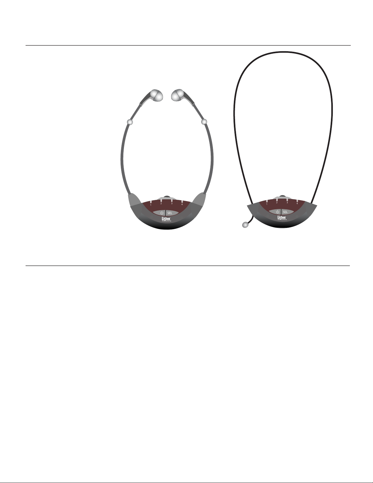
LR-42/44 Package Contents
1
2 3
4
1
2 3
4
1
2 3
4
• LR-42 IR Stethoscope 4-Channel Receiver (or)
LR-44 IR Lanyard 4-Channel Receiver
• Quick Reference Card
Listen Part Number
• LR-42
• LR-44
LR-42 LR-44
3
l
Page 4
LR-42 IR Stethoscope Receiver Specications
Architectural Specication
The IR stethoscope receiver shall be capable of receiving on four carriers (2.3, 2.8, 3.3, 3.8
MHz) and the channel shall be displayed on one of four front panel LEDs. The receiver shall
be capable of being locked on a channel. The receiver shall be capable of receiving a stereo
signal on each of the four carriers. The receiver shall have a SNR of 60 dB or greater and
have built in squelch control. The device shall have an audio frequency response of 63 Hz
to 15 kHz, +/- 3dB and shall have distortion of less than 2%. The device shall operate for 30
hours with two AAA alkaline batteries and 15 hours with two AAA NiMH rechargeable batteries. The receiver shall be covered by a limited lifetime warranty. The LR-42 is specied.
Specications LR-42
Carrier Frequencies Selectable: 2.3 MHz, 2.8 MHz, 3.3 MHz, 3.8 MHz
Number of Channels Four (4) selectable channels
IR Detectors Two (2) detectors under front IR lens
RF
Sensitivity One (1) nW/cm2 at 40 dB SNR
Frequency Accuracy +/- .005% stability 0 to 50C
Squelch Automatic on loss of RF signal (40 dB SNR)
Compliance FCC Part 15, Industry Canada, CE, RoHS
Audio
Controls
Indicators
Power
Physical
** All system specications are wireless end-to-end
System Frequency Response 63Hz - 15kHz (+/- 3dB)
System Signal to Noise Ratio
(A-weighted)
System Distortion <2% total harmonic distortion (THD)
Audio Output Jacks 3.5 mm connector unbalanced, mono or stereo headphones
Audio Output Power 20 mW maximum at 32 ohms
User Controls Volume, Power, Channel Select
Programming Channel Lock, Auto Seek, Channel Lock-Out, Squelch
Unit Power Indicated by current channel selection LED
Channel Selection Red LED illuminates on the current channel selection
Battery Type Two (2) AAA alkaline batteries or NiMH battery pack
Battery Life 30 hours alkaline, 15 hours NiMH rechargeable pack
Battery Charging Up to 9 hours, Fully Automatic with NiMH battery pack and LA-350 charger
Dimensions (H x W x D) 1.8 x 4.0 x .75 in (46x102x19 mm) Stethoscope Arm length 8 in (203 mm)
Color Grey with White Silk Screening
Unit Weight without batteries 1.75 oz. (49 g)
Unit Weight with batteries 2.55 oz. (74 g)
Shipping Weight 8.00 oz. (227 grams)
Mono: >60dB
Stereo: >52dB
(LA-364)
4
Environmental
l
Temperature - Operation -10 C (14 F) to +40 (104 F)
Temperature - Storage -20 C (-4 F) to +50 (122 F)
Humidity 0 to 95% relative humidity, non-condensing
•Specications are subject to change without notication.
Page 5
LR-44 Lanyard IR Receiver Specications
Architectural Specication
The Lanyard IR Receiver shall be capable of receiving on four carriers (2.3, 2.8, 3.3, 3.8 MHz)
and the channel shall be displayed on one of four front panel LEDs. The receiver will accept
mono or stereo earphones with a 3.5 mm connector. The receiver shall be capable of being
locked on a channel. The receiver shall be capable of receiving a stereo signal on each of the
four carriers. The receiver shall have a SNR of 60 dB or greater and have built in squelch
control. The device shall have an audio frequency response of 63 Hz to 15 kHz, +/- 3dB and
shall have distortion of less than 2%. The device shall operate for 30 hours with two AAA
alkaline batteries and 15 hours with two AAA NiMH rechargeable batteries. The receiver
shall be covered by a limited lifetime warranty. The LR-44 is specied.
Specications LR-44
Carrier Frequencies Selectable: 2.3 MHz, 2.8 MHz, 3.3 MHz, 3.8 MHz
Number of Channels Four (4) selectable channels
IR Detectors Two (2) detectors under front IR lenss
RF
Sensitivity One (1) nW/cm2 at 40 dB SNR
Frequency Accuracy +/- .005% stability 0 to 50C
Squelch Automatic on loss of RF signal (40 dB SNR)
Compliance FCC Part 15, Industry Canada, CE, RoHS
Audio
Controls
Indicators
Power
Physical
** All system specications are wireless end-to-end
System Frequency Response 63Hz - 15kHz (+/- 3dB)
System Signal to Noise Ratio
(A-weighted)
System Distortion <2% total harmonic distortion (THD)
Audio Output Jacks 3.5 mm connector unbalanced, mono or stereo headphones
Audio Output Power 20 mW maximum at 32 ohms
User Controls Volume, Power, Channel Select
Programming Channel Lock, Auto Seek, Channel Lock-Out, Squelch
Unit Power Indicated by current channel selection LED
Channel Selection Red LED illuminates on the current channel selection
Battery Type Two (2) AAA alkaline batteries or NiMH battery pack
Battery Life 30 hours alkaline, 15 hours NiMH rechargeable pack
Battery Charging Up to 9 hours, Fully Automatic with NiMH battery pack and LA-350 charger
Dimensions (H x W x D) 1.80 x 4.00 x 0.75 in. (46 x 102 x 19 mm)
Color Grey with White Silk Screening
Unit Weight without batteries 1.75 oz. (49 g)
Unit Weight with batteries 2.55 oz. (74 g)
Shipping Weight 8.00 oz. (227 g)
Mono: >60dB
Stereo: >52dB
(LA-364)
Environmental
Temperature - Operation -10 C (14 F) to +40 (104 F)
Temperature - Storage -20 C (-4 F) to +50 (122 F)
Humidity 0 to 95% relative humidity, non-condensing
•Specications are subject to change without notication.
l
5
Page 6
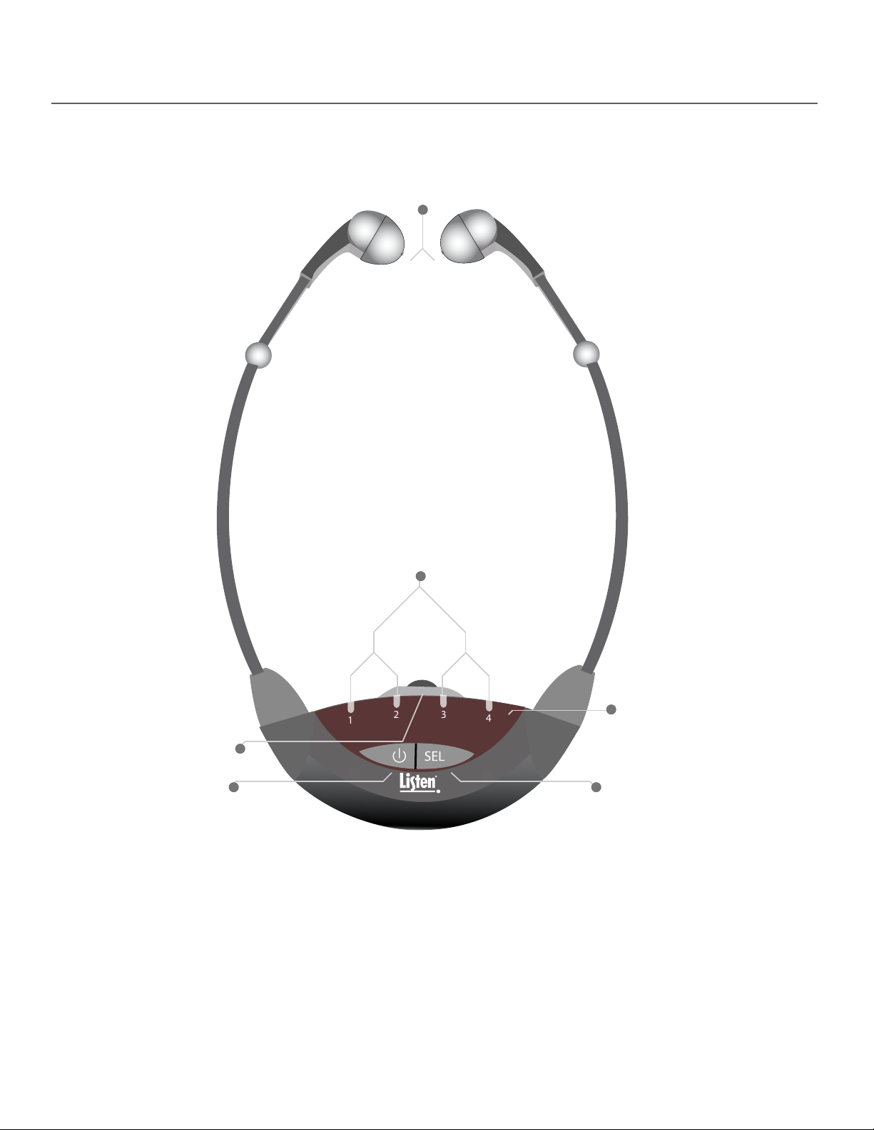
LR-42 Quick Reference
1
2 3
4
1
2 3
4
Stetho Arms (LR-42 model only):
Speakers located in ends of stetho
arms, place in ears to listen to audio
Volume Control Dial:
Use to adjust volume
level in speaker(s)
Power Button:
Press to turn unit on, press
and hold to turn unit o
Channel Indicator LEDs:
Displays which channel the unit
is currently tuned to. Also can
display battery level, etc.
IR Receiver Lens: Lens covers the
IR receiving components, ensure
entire lens is visible during use
Select Button:
Press to change the
channel, also used with
programming function
6
l
Page 7
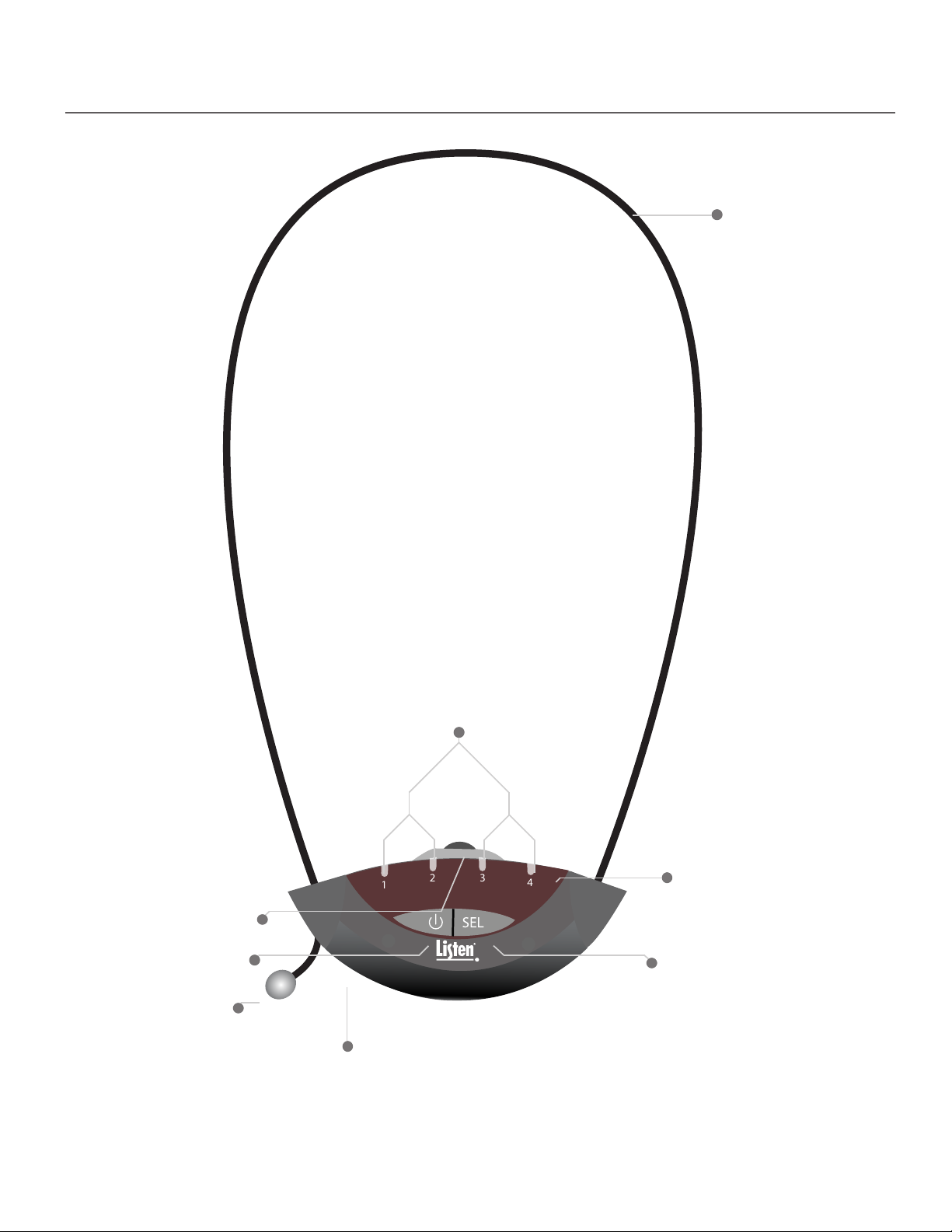
LR-44 Quick Reference
1
2 3
4
Lanyard (LR-44 model only):
Holds receiver in place below
chin of wearer
Volume Control Dial:
Use to adjust volume
level in speaker(s)
Power Button:
Press to turn unit on, press
and hold to turn unit o
Lanyard Adjustment Ball
(LR-44 model only):
Adjust the loop size of the
lanyard by pulling on this
ball (usually done after unit
is on user’s body)
Channel Indicator LEDs:
Displays which channel the
unit is currently tuned to.
Also can display battery
level, etc.
IR Receiver Lens: Lens covers the
IR receiving components, ensure
entire lens is visible during use
Select Button:
Press to change the
channel, also used with
programming function
Headset Jack (LR-44 model only):
Accepts any earpiece with a
3.5 mm TRS connector
l
7
Page 8

LR-42/44 Setup Instructions
Listen Support: 800.330.0891
801.233.8992, www.listentech.com
Model: 4-Channel IR Receiver
FCC: This device complies with Part 15 of the FCC Rules.
IC: This Class A digital apparatus complies with Canadian ICES-003.
Listen Support: 800.330.0891
801.233.8992, www.listentech.com
Model: 4-Channel IR Receiver
FCC: This device complies with Part 15 of the FCC Rules.
IC: This Class A digital apparatus complies with Canadian ICES-003.
Listen Support: 800.330.0891
801.233.8992, www.listentech.com
Model: 4-Channel IR Receiver
FCC: This device complies with Part 15 of the FCC Rules.
IC: This Class A digital apparatus complies with Canadian ICES-003.
Listen Support: 800.330.0891
801.233.8992, www.listentech.com
Model: 4-Channel IR Receiver
FCC: This device complies with Part 15 of the FCC Rules.
IC: This Class A digital apparatus complies with Canadian ICES-003.
1
Listen Support: 800.330.0891
801.233.8992, www.listentech.com
Model: 4-Channel IR Receiver
FCC: This device complies with Part 15 of the FCC Rules.
IC: This Class A digital apparatus complies with Canadian ICES-003.
1
2 3
4
Listen Support: 800.330.0891
801.233.8992, www.listentech.com
Model: 4-Channel IR Receiver
FCC: This device complies with Part 15 of the FCC Rules.
IC: This Class A digital apparatus complies with Canadian ICES-003.
Listen Support: 800.330.0891
801.233.8992, www.listentech.com
Model: 4-Channel IR Receiver
FCC: This device complies with Part 15 of the FCC Rules.
IC: This Class A digital apparatus complies with Canadian ICES-003.
Unpack the Product
1
Remove outer packaging and plastic cover. Verify all components are
present and that no physical damage has occurred to the product.
Determine Battery Type to be Used
2
Alkaline Batteries: If using alkaline batteries install them in alkaline battery compartment attached to
2A
rear of unit using the following process (purchase Listen Technologies part number LA-363).
1
Remove alkaline battery compartment
Press down on compartment and push towards the bottom of unit.
2
Open battery compartment
Open by pulling into two pieces using the grips on the top of the compartment.
8
l
3
4
5
Grips
Install batteries
Insert two AAA alkaline batteries in compartment noting polarity.
Close battery compartment
Snap the two compartment pieces back together.
Return battery compartment to rear of receiver.
Place battery compartment on rear of receiver.
Page 9
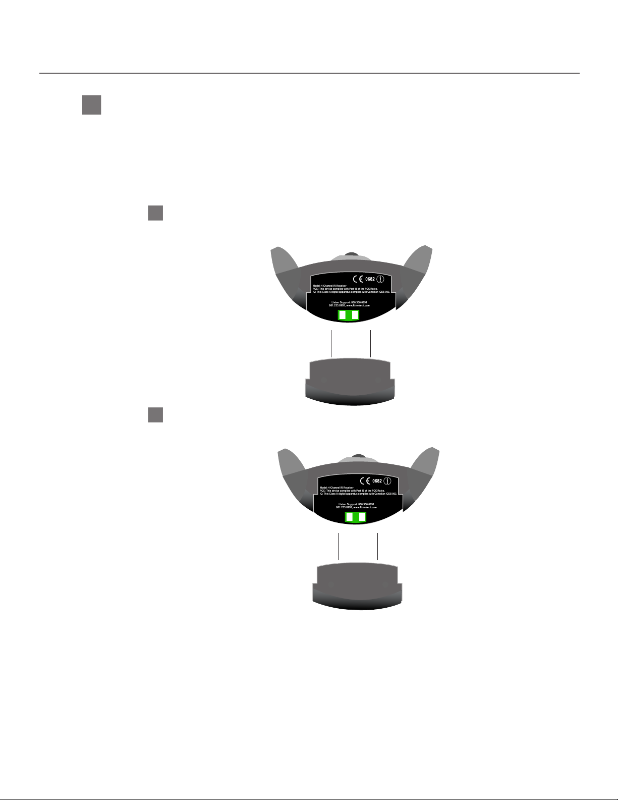
LR-42/44 Setup Instructions
Listen Support: 800.330.0891
801.233.8992, www.listentech.com
Model: 4-Channel IR Receiver
FCC: This device complies with Part 15 of the FCC Rules.
IC: This Class A digital apparatus complies with Canadian ICES-003.
Listen Support: 800.330.0891
801.233.8992, www.listentech.com
Model: 4-Channel IR Receiver
FCC: This device complies with Part 15 of the FCC Rules.
IC: This Class A digital apparatus complies with Canadian ICES-003.
Listen Support: 800.330.0891
801.233.8992, www.listentech.com
Model: 4-Channel IR Receiver
FCC: This device complies with Part 15 of the FCC Rules.
IC: This Class A digital apparatus complies with Canadian ICES-003.
Listen Support: 800.330.0891
801.233.8992, www.listentech.com
Model: 4-Channel IR Receiver
FCC: This device complies with Part 15 of the FCC Rules.
IC: This Class A digital apparatus complies with Canadian ICES-003.
2B
Rechargeable NiMH batteries: To use rechargable NiMH batteries in the receiver you will need to purchase an
NiMH rechargeable battery pack, Listen Technologies part number LA-364.
IMPORTANT: Do not install AAA NiMH batteries in included alkaline battery pack, because the batteries will
not charge in this pack; only use a Listen Technologies provided sealed battery pack (LA-364)
for battery charging.
Install LA-364 battery pack using the following process:
1
Remove alkaline battery compartment
Remove alkaline battery compartment by pressing down on compartment and pushing
towards the bottom of unit. Store alkaline battery pack for later use if desired.
2
Place LA-364 battery pack in receiver
Place LA-364 battery pack in receiver. The unit will now recognize the rechargeable
batteries and charge them correctly when unit is placed in a charging case (LA-350).
To charge, refer to charging section.
l
9
Page 10
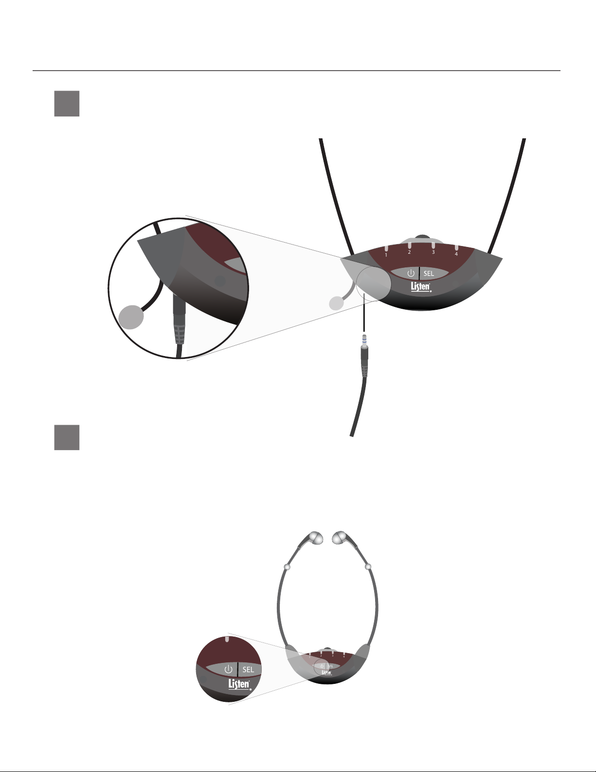
LR-42/44 Setup Instructions
1
2 3
4
1
2 3
4
1
2 3
4
2 3
4
1
2 3
4
2 3
4
1
2 3
4
1
2 3
4
2 3
4
1
2 3
4
2 3
4
1
2 3
4
Connect an Earphone or Headset (LR-44 model
3
only)
An earphone or headset will connect to the jack on the bottom of the unit. Either mono or
stereo connectors may be used with Listen Technologies receivers. Make sure to push the
connector all the way into the jack.
10
l
4
Turn Unit On
Turn the unit on by pressing either button on the front of the unit.
ATTENTION 1: The LR-44 model must have a headset connected to the unit to turn on and
ATTENTION 2: If using a new LA-364 NiMH battery pack the batteries may need to be put
remain on for longer than ten seconds.
through one charge cycle before they will turn the unit on.
Page 11

LR-42/44 Setup Instructions
Select a Channel and/or Program Channel Selection Method
5
The Select button is used to change the channel. Press the button once to change the channel. The unit
will either seek or scroll through the channels depending upon which channel selection method you have
enabled. See below for description of possible channel selection methods.
Upon Power up
5A
When set to factory defaults the unit will turn on to the last channel is was tuned to upon power
up. However, the unit can be programmed to continuously seek for a channel with signal upon
power up until one is found (Auto-Seek). See page 19 for more programming information.
Single Channel Systems
5B
If you know what channel the unit will be used on, and you know that there is only one
channel that the unit will need to be used on, you can lock it onto that channel now.
See page 18 for channel lock information.
Multiple Channel Systems
5C
In systems that require the receivers to be able to access more than one channel you
must decide which type of channel selection method you want enabled. The default
setting is that each time you press the Select button the unit will scroll to the next
channel. If you want the receiver to automatically begin seeking for another channel
when the signal is lost (such as walking from room to room in a museum) the Auto-Seek
function must be enabled. See page 19 for more information.
Select Stereo/Mono Mode
6
If the receiver will be receiving a mono signal (stereo mode is not enabled on LT-82) no action is required as
Mono Mode is the default setting. However, if the receiver will be receiving a stereo signal the receiver must
be set to Stereo Mode to function properly.
Setup Additional Programming (if desired)
7
Additional programming options, in addition to the Auto-Seek and Stereo/Mono Mode functions described
above, are the Channel Lock-out and Squelch setting. See page 19 for a complete explanation of the
programming functions for the receiver.
l
11
Page 12
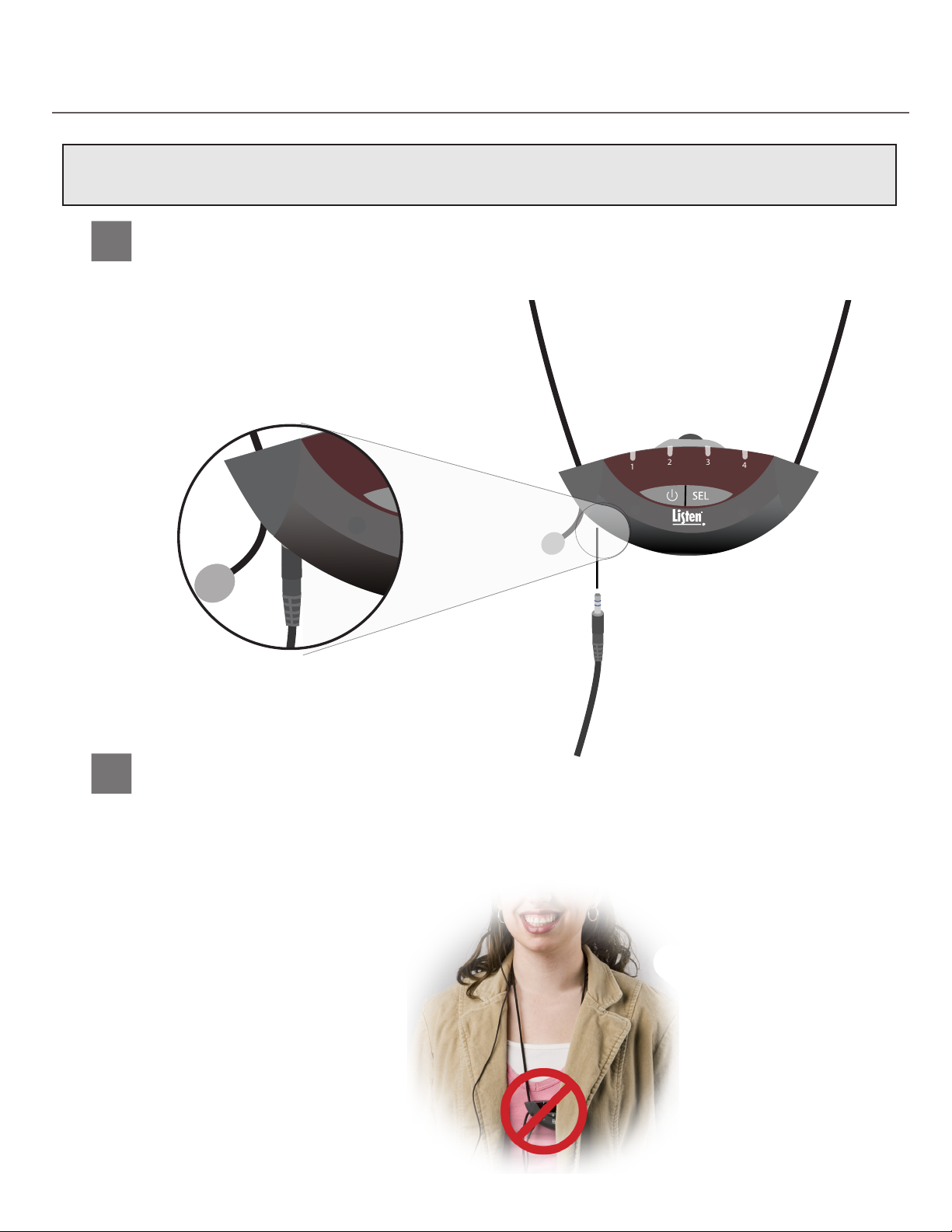
LR-42/44 Operating Instructions
1
2 3
4
2 3
4
1
2 3
4
2 3
4
1
2 3
4
NOTE: The following operating instructions briey describe how a unit operates based on which programming features
have been enabled/disabled, with the factory default settings highlighted. See page 19 for detailed
information about programming and operating units using non-default settings.
Connect an Earphone or Headset (LR-44 Model Only)
1
An earphone or headset will connect to the jack on the bottom of the unit. Either mono or stereo
connectors may be used with Listen Technologies receivers. Make sure to push the connector all
the way into the jack.
2
12
l
Position the Unit on User’s Body
ATTENTION: If desired, this step can be done after turning the unit on and selecting a channel as long as
the front of the receiver is not obstructed during the channel selection process.
IMPORTANT: Always wear the receiver in such a way that there is nothing covering the front lens of the
receiver. If the front lens is covered or obstructed the receiver will have very poor range.
Page 13
LR-42/44 Operating Instructions
1
2 3
4
1
2 3
4
1
2 3
4
1
2 3
4
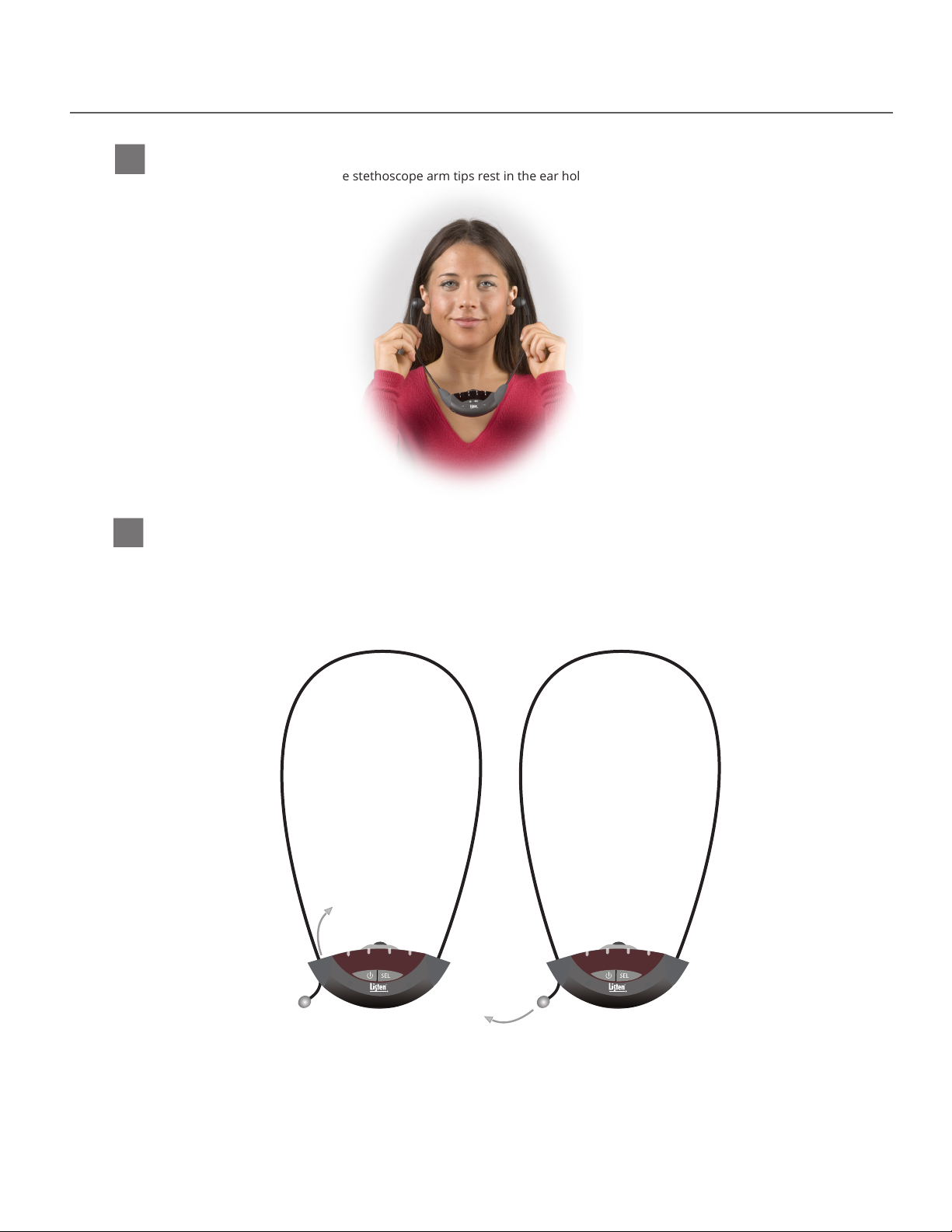
LR-42
2A
Position the receiver so the stethoscope arm tips rest in the ear holding the unit below the
chin of the user.
LR-44
2B
Position the lanyard around the neck holding the unit below the chin of the user. If desired,
pull on the lanyard adjustment ball to decrease the size of the lanyard loop (bringing the unit
closer to the user’s chin). To increase the size of the lanyard loop pull on the lanyard cord
above the point it passes through the receiver.
l
13
2 3
1
4
2 3
1
4
Page 14
LR-42/44 Operating Instructions
1
2 3
4
1
2 3
4
1
2 3
4
2 3
4
1
2 3
4
2 3
4
1
2 3
4
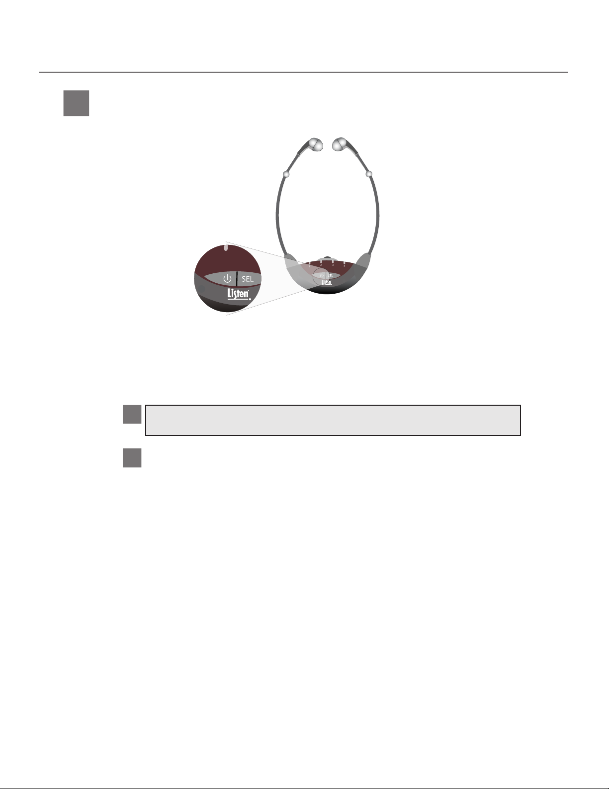
Turn the Unit On
3
Turn on the unit by pressing either button on the front of the receiver.
ATTENTION 1: The LR-44 model must have a headset connected to the unit to turn
on and remain on for longer than ten seconds.
ATTENTION 2: If using a new LA-364 NiMH battery pack the batteries may need to
be put through one charge cycle before they will turn the unit on.
3A
Auto-Seek Disabled (Default OFF)
The unit will power up to the same channel that it was on when it was last turned o.
Auto-Seek Enabled
3B
The unit will power up to the same channel that it was on when it was last turned o. If no
signal is present on that channel, it will seek for a channel with signal present. If none is
found, it will continue seeking until it nds a signal. Note that if the unit has been locked
on its channel, this lock will override Auto-Seek
To turn the unit o press and hold the PWR button for 1.5 seconds.
14
l
Page 15
LR-42/44 Operating Instructions
1
2 3
4
1
2 3
4
2 3
4
4
2 3
4
1
2 3
4
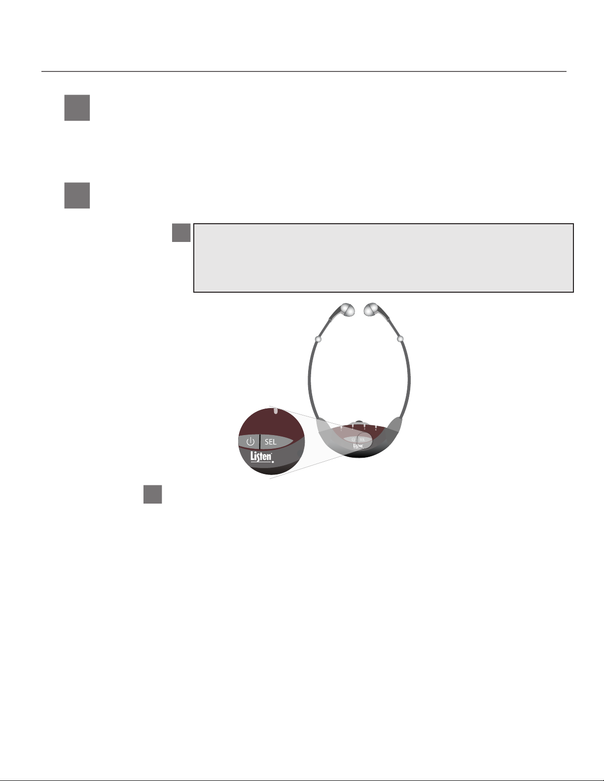
LED Sleep Mode
4
The receiver will shut o the channel indicator LEDs after a period of 10 seconds passes without any
buttons being pressed. The receiver will still produce audio and the volume can still be adjusted, only the
LEDs shut down. It will be necessary to “wake up” the receiver by tapping either the PWR or Select button
before doing many of the operating tasks described in the next sections.
Select Listening Channel
5
Selecting Channel with:
Auto-Seek Disabled (Default OFF)
5A
Press the Select button to scroll through the four channels. If the channel indicator LED
ashes four times when Select is pressed, and the unit does not change channels, it is locked
on the current channel. See page 18 for channel lock information. Also, if the unit “skips” over
the desired channel it is because that channel has been locked out. See page 19 for more
information about the programmable features.
Auto-Seek Enabled
5B
The unit will continuously seek for a signal until one is found and then it will stay on that
channel. If the signal is not detected for a short time period, or the user presses the SEL
button, the unit will seek for another signal and will keep seeking until a signal is detected. If,
however, the unit is locked on the current channel this lock will “override” Auto-Seek and the
unit will not change channels when the signal is lost. Also, if there are channels that have been
locked out in the Channel Lock Out mode the Auto-Seek will not stop on these channels. See
page 19 for more information.
15
l
Page 16
LR-42/44 Operating Instructions
1
2 3
4
1
2 3
4
1
2 3
4
1
2 3
4
1
2 3
4
1
2 3
4
1
2 3
4
1
2 3
4
1
2 3
4
1
2 3
4
2 3
4
1
2 3
4
2 3
4
1
2 3
4
1
2 3
4
1
2 3
4
1
2 3
4
1
2 3
4
1
2 3
4
Stereo Mode
Channel Lock-Out
Auto-Seek
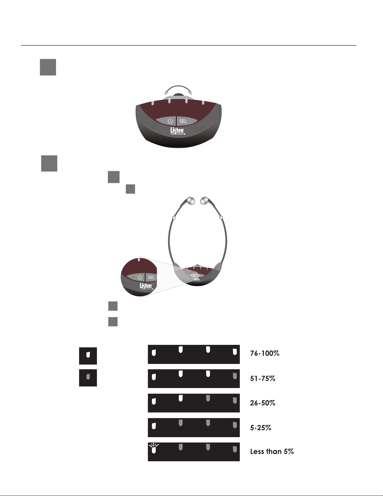
Adjust Volume Level
6
Use the control dial on the top of the unit to adjust the volume to a comfortable level.
Checking Battery Level and Current Channel
7
Checking Battery Level
7A
1
Tapping the power button will display the battery level on the channel indicator LEDs.
16
l
2
When a battery check is initiated all four LEDs will turn on. Then the LEDs will ramp down to the
current battery level. If all four LEDs turn on and remain on the batteries are full.
3
The battery level will then display on the channel indicator LEDs for two seconds (unless battery
level is less than about 5%, in which rst LED will ash for ve seconds). Each lit channel indicator
LED on
LED off
represents approximately 25% of the battery’s capacity. (see chart below).
1
1
1
1
1
2 3
2 3
2 3
2 3
2 3
4
4
4
4
4
Page 17
LR-42/44 Operating Instructions
1
2 3
4
1
2 3
4
1
2 3
4
1
2 3
4
1
2 3
4
2 3
4
1
2 3
4
2 3
4
1
2 3
4
2 3
4
1
2 3
4
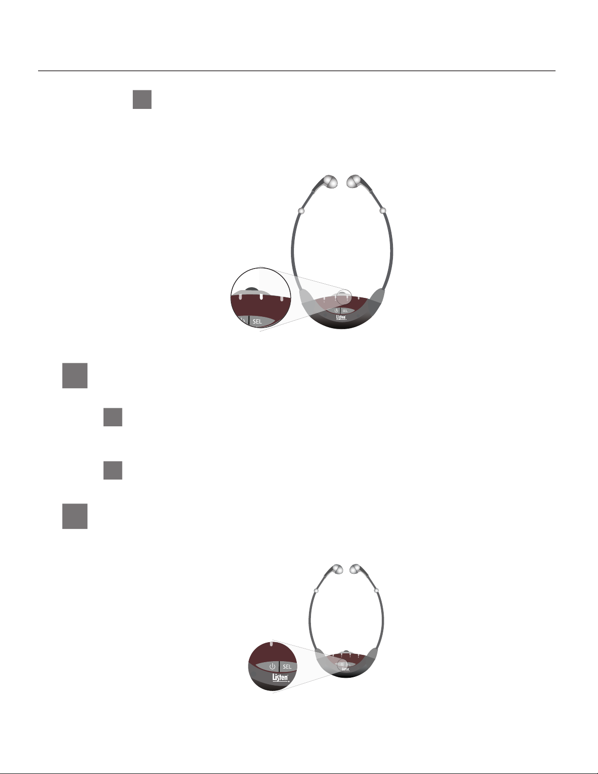
Checking Current Channel
7B
The channel the unit is currently on is represented by the corresponding LED in the channel indicator
LEDs being lit (unless unit is in LED sleep mode). To check which channel the unit is on without
changing the current channel while the unit is in LED sleep mode, press either the PWR or Select
button once. This will turn the channel indicator LEDs back on for 10 seconds.
2 3
1
4
Auto Shut-O Feature
8
The receiver will automatically turn o in the two following situations:
After 10 seconds
1
After 10 seconds if there is no headset plugged into the headset jack (LR-44 model only). This
allows for a quick battery status check without having to plug in a headset.
This function is also disabled while in Program Mode.
After 30 minutes
2
After 30 minutes if no signal is detected by the receiver (both models).
Powering down the unit
9
To power down the unit press and hold the PWR button for 1.5 seconds. All of the LEDs will light up
momentarily and then turn o signaling power has been shut o.
17
l
Page 18

LR-42/44 Locking Instructions
Locking the Receiver on One Channel
The unit can be electronically locked on one channel so that it will not change channel even if the Select button is
pressed. It is recommended to lock the receivers on the channel that is being used in systems that do not require the
user to change channels (single channel systems).
Channel Lock Procedure
The unit can be electronically locked on the channel it is currently on using the following process.
1
Select the channel that you want to lock the unit on.
2
Wait until the unit enters LED sleep mode. LED sleep mode begins when the unit extinguishes the
channel indicator LED which will happen 10 seconds after the last button is pressed.
3
Once in LED sleep mode, press and hold both the Select and Power buttons for three seconds.
4
After holding for three seconds, the channel indicator LED will ash once indicating that the unit
has been successfully locked. Once the channel indicator LED ashes you can release the Power
and Select buttons.
Channel Unlock Procedure
The procedure for unlocking the unit is the same as locking the unit.
Lock Indicators
If you press the Select button to change the channel when the unit is locked, the channel indicator LED will
ash four times and the unit will not change channels. Follow the lock/unlock procedure shown above to be
able to change the channel.
18
l
Page 19
LR-42/44 Programming Instructions
1
2 3
4
1
2 3
4
Program Mode Overview
The following features can be programmed within the program mode: Stereo On/O, Channel Lock Out, Auto
Seek and Squelch. The following sections outline the procedures required to enter the program mode, modify the
programmable features and exit the program mode. There are also several examples of how to use the program
mode to change the settings of the receiver. Lastly, the end of this programming section provides a detailed
description about each programmable feature and when they can or should be used.
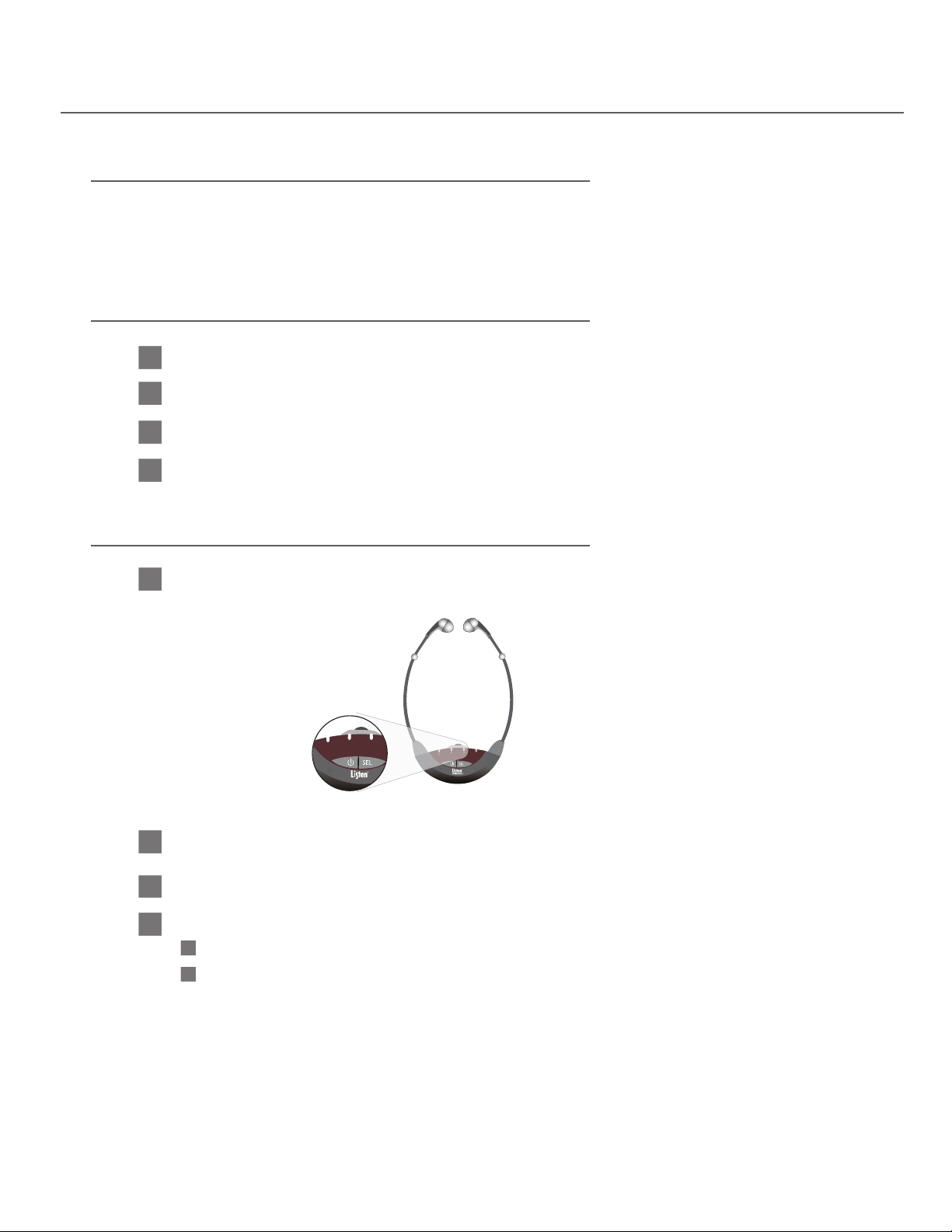
Entering Program Mode
1
Make sure that the unit is o (not just in LED sleep mode).
2
Press and hold the Power and Select buttons for three seconds.
When program mode is entered all four LEDs will ash once indicating successful entry into program mode.
3
4
Immediately after the LEDs ash the channel one LED will come on. This represents the rst of the programmable
features, the Stereo On/O function.
While in Program Mode
1
The Channels 1, 2, and 3 LED indicators are used to display which programmable feature is
currently selected.
2 3
4
1
2
The Channel 4 LED indicator shows whether the Stereo On/O and Auto-Seek features are
enabled or disabled. If the Channel 4 LED is on, these features are enabled.
Press the Select button to advance to the next program mode feature.
3
4
Press the Power button to:
4A
Enable or disable the Stereo On/O and Auto-Seek Features (or),
4B
Enter the program “sub-mode” required to adjust the Channel Lock-Out and Squelch features.
19
l
Page 20
LR-42/44 Programming Instructions
1
2 3
4
Stereo ModeLED on
1
2 3
4
1
2 3
4
Stereo ModeLED on
Channel Lock-OutLED off
1
2 3
4
1
2 3
4
1
2 3
4
Stereo ModeLED on
Channel Lock-OutLED off
Auto-Seek
1
2 3
4
1
2 3
4
1
2 3
4
1
2 3
4
Stereo ModeLED on
Channel Lock-OutLED off
Auto-Seek
Squelch
1
2 3
4
1
2 3
4
1
2 3
4
1
2 3
4
Stereo ModeLED on
Channel Lock-OutLED off
Auto-Seek
Squelch
1
2 3
4
Spare
1
2 3
4
1
2 3
4
1
2 3
4
1
2 3
4
Stereo ModeLED on
Channel Lock-OutLED off
Auto-Seek
Squelch
1
2 3
4
Spare
1
2 3
4
Reset To Defaults
1
2 3
4
1
2 3
4
1
2 3
4
1
2 3
4
Stereo ModeLED on
Channel Lock-OutLED off
Auto-Seek
Squelch
1
2 3
4
Spare
1
2 3
4
Reset To Defaults
1
2 3
4
Exit Program
1
2 3
4
1
2 3
4
Stereo ModeLED on
Channel Lock-OutLED off
1
2 3
4
Stereo ModeLED on
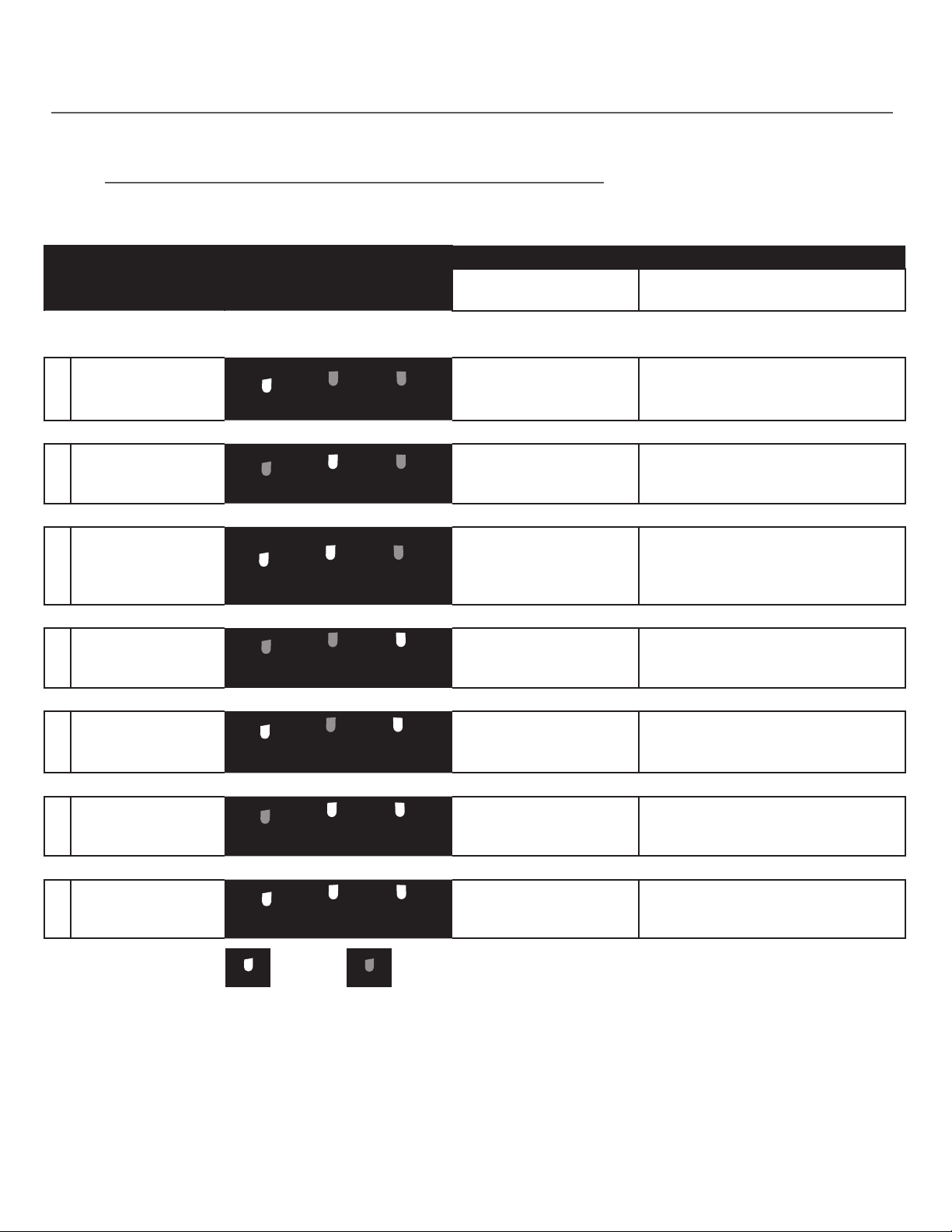
Program Mode Functionality Diagram
Use this chart to help with navigating through, and adjusting the features within, the program mode.
Programmable
Feature
Receiver LED Display Shows
Navigating within the Program Mode
Pressing the
Select Button
1 Stereo On/O Advances to Feature 2
2 Channel Lock-Out Advances to Feature 3
3 Auto-Seek Advances to Feature 4
4 Squelch Advances to Feature 5
Pressing the Power Button
Toggles Stereo On/O. LED 4
illuminated indicates stereo is ON
default : o
Enters Channel Lock-Out
“Sub-Mode” (See next page for
instructions)
Toggles Auto Seek On/O. LED 4
illuminated indicates
Auto-Seek is ON
default : o
Enters Squelch Adjustment
“Sub-Mode”
(See page 105)
5 No Function Advances to Feature 6 No Function
Unit ashes all LED’s 3 times
6 Reset to Defaults Advances to Feature 7
indicating reset and then
the unit shuts o
7 Exit Program Mode Returns to Feature 1
Exits Program Mode and returns to
standard operating mode
20
l
Page 21
LR-42/44 Programming Instructions
1
2 3
4
1
2 3
4
0 (no squelch)
1
1
2 3
4
1
2 3
4
1
2 3
4
0 (no squelch)
1
2
1
2 3
4
1
2 3
4
1
2 3
4
1
2 3
4
0 (no squelch)
1
2
3
1
2 3
4
1
2 3
4
1
2 3
4
1
2 3
4
2 3
4
0 (no squelch)
1
2
3
4
1
2 3
4
1
2 3
4
1
2 3
4
1
2 3
4
1
2 3
4
2 3
4
0 (no squelch)
1
2
3
4
5
1
2 3
4
1
2 3
4
1
2 3
4
1
2 3
4
1
2 3
4
1
2 3
4
2 3
4
0 (no squelch)
1
2
3
4
5
6
1
2 3
4
1
2 3
4
1
2 3
4
1
2 3
4
1
2 3
4
1
2 3
4
2 3
4
1
2 3
4
0 (no squelch)
1
2
3
4
5
6
7
1
2 3
4
1
2 3
4
1
2 3
4
1
2 3
4
1
2 3
4
1
2 3
4
1
2 3
4
1
2 3
4
2 3
4
0 (no squelch)
1
2
3
4
5
6
7
8
1
2 3
4
1
2 3
4
1
2 3
4
1
2 3
4
1
2 3
4
1
2 3
4
1
2 3
4
1
2 3
4
1
2 3
4
1
2 3
4
0 (no squelch)
1
2
3
4
5
6
7
8
9
1
2 3
4
1
2 3
4
1
2 3
4
1
2 3
4
1
2 3
4
1
2 3
4
1
2 3
4
1
2 3
4
1
2 3
4
1
2 3
4
2 3
4
0 (no squelch)
1
2
3
4
5
6
7
8
9
10
1
2 3
4
1
2 3
4
1
2 3
4
1
2 3
4
1
2 3
4
1
2 3
4
1
2 3
4
1
2 3
4
1
2 3
4
1
2 3
4
1
2 3
4
1
2 3
4
0 (no squelch)
1
2
3
4
5
6
7
8
9
10
11
1
2 3
4
1
2 3
4
1
2 3
4
1
2 3
4
1
2 3
4
1
2 3
4
1
2 3
4
1
2 3
4
1
2 3
4
1
2 3
4
1
2 3
4
1
2 3
4
1
2 3
4
0 (no squelch)
1
2
3
4
5
6
7
8
9
10
11
12
1
2 3
4
1
2 3
4
1
2 3
4
1
2 3
4
1
2 3
4
1
2 3
4
1
2 3
4
1
2 3
4
1
2 3
4
1
2 3
4
1
2 3
4
1
2 3
4
1
2 3
4
2 3
4
0 (no squelch)
1
2
3
4
5
6
7
8
9
10
11
12
13
1
2 3
4
1
2 3
4
1
2 3
4
1
2 3
4
1
2 3
4
1
2 3
4
1
2 3
4
1
2 3
4
1
2 3
4
1
2 3
4
1
2 3
4
1
2 3
4
1
2 3
4
1
2 3
4
2 3
4
0 (no squelch)
1
2
3
4
5
6
7
8
9
10
11
12
13
14
1
2 3
4
1
2 3
4
1
2 3
4
1
2 3
4
1
2 3
4
1
2 3
4
1
2 3
4
1
2 3
4
1
2 3
4
1
2 3
4
1
2 3
4
1
2 3
4
1
2 3
4
1
2 3
4
1
2 3
4
1
2 3
4
0 (no squelch)
1
2
3
4
5
6
7
8
9
10
11
12
13
14
15 (tightest/lest range)
1
2 3
4
1
2 3
4
1
2 3
4
0 (no squelch)
1
2
1
2 3
4
1
2 3
4
1
2 3
4
1
2 3
4
LED on (channel active)
0 (no squelch)
1
2
3
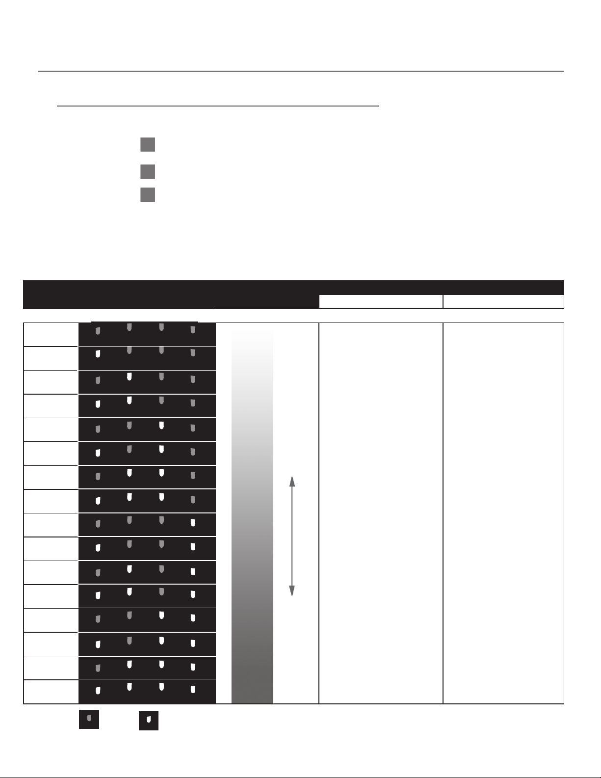
Channel Lock-Out “Sub-Mode” Instructions
While in Channel Lock-Out “Sub-Mode”
1
The channels that would be available are represented by the corresponding channel
indicator LED being on and the channels that would be “locked out” are represented by the
channel indicator LED being o.
2
Press the Select button to advance to the next channel(s) active combination.
3
Press the Power button to save the selected channel(s) active combination and return to regular mode
(the Auto-Seek function will be the selected feature).
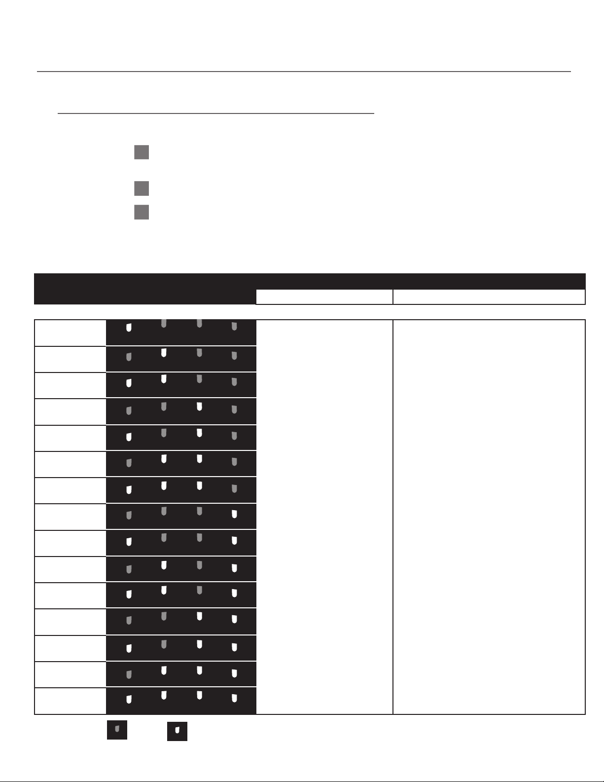
Channel Lock-Out “Sub-Mode” Functionality Diagram
Use this chart to help with navigating through, and adjusting the channels active, within the Channel Lock-Out “Sub-Mode”.
Channels
Active
1
2
1,2
3
1,3
2,3
1,2,3
4
1,4
2,4
1,2,4
3,4
1,3,4
2,3,4
1,2,3,4
(default)
Receiver LED Display Shows:
LED off
LED on (channel active)
Navigating within the Channel Lock-Out “Sub-Mode”
Pressing the Select Button Pressing the Power Button
Advances to the next
channel(s) active
combination
Saves the selected channel(s) active
combination and returns to regular
program mode
l
21
Page 22
LR-42/44 Programming Instructions
1
2 3
4
1
2 3
4
1
2 3
4
LED on (channel active)
0 (no squelch)
1
2
1
2 3
4
1
2 3
4
1
2 3
4
1
2 3
4
LED on (channel active)
LED off
0 (no squelch)
1
2
3
1
2 3
4
1
2 3
4
0 (no squelch)
1
1
2 3
4
1
2 3
4
1
2 3
4
0 (no squelch)
1
2
1
2 3
4
1
2 3
4
1
2 3
4
1
2 3
4
0 (no squelch)
1
2
3
1
2 3
4
1
2 3
4
1
2 3
4
1
2 3
4
2 3
4
0 (no squelch)
1
2
3
4
1
2 3
4
1
2 3
4
1
2 3
4
1
2 3
4
1
2 3
4
2 3
4
0 (no squelch)
1
2
3
4
5
1
2 3
4
1
2 3
4
1
2 3
4
1
2 3
4
1
2 3
4
1
2 3
4
2 3
4
0 (no squelch)
1
2
3
4
5
6
1
2 3
4
1
2 3
4
1
2 3
4
1
2 3
4
1
2 3
4
1
2 3
4
2 3
4
1
2 3
4
0 (no squelch)
1
2
3
4
5
6
7
1
2 3
4
1
2 3
4
1
2 3
4
1
2 3
4
1
2 3
4
1
2 3
4
1
2 3
4
1
2 3
4
2 3
4
0 (no squelch)
1
2
3
4
5
6
7
8
1
2 3
4
1
2 3
4
1
2 3
4
1
2 3
4
1
2 3
4
1
2 3
4
1
2 3
4
1
2 3
4
1
2 3
4
1
2 3
4
0 (no squelch)
1
2
3
4
5
6
7
8
9
1
2 3
4
1
2 3
4
1
2 3
4
1
2 3
4
1
2 3
4
1
2 3
4
1
2 3
4
1
2 3
4
1
2 3
4
1
2 3
4
2 3
4
0 (no squelch)
1
2
3
4
5
6
7
8
9
10
1
2 3
4
1
2 3
4
1
2 3
4
1
2 3
4
1
2 3
4
1
2 3
4
1
2 3
4
1
2 3
4
1
2 3
4
1
2 3
4
1
2 3
4
1
2 3
4
0 (no squelch)
1
2
3
4
5
6
7
8
9
10
11
1
2 3
4
1
2 3
4
1
2 3
4
1
2 3
4
1
2 3
4
1
2 3
4
1
2 3
4
1
2 3
4
1
2 3
4
1
2 3
4
1
2 3
4
1
2 3
4
1
2 3
4
0 (no squelch)
1
2
3
4
5
6
7
8
9
10
11
12
1
2 3
4
1
2 3
4
1
2 3
4
1
2 3
4
1
2 3
4
1
2 3
4
1
2 3
4
1
2 3
4
1
2 3
4
1
2 3
4
1
2 3
4
1
2 3
4
1
2 3
4
2 3
4
0 (no squelch)
1
2
3
4
5
6
7
8
9
10
11
12
13
1
2 3
4
1
2 3
4
1
2 3
4
1
2 3
4
1
2 3
4
1
2 3
4
1
2 3
4
1
2 3
4
1
2 3
4
1
2 3
4
1
2 3
4
1
2 3
4
1
2 3
4
1
2 3
4
2 3
4
0 (no squelch)
1
2
3
4
5
6
7
8
9
10
11
12
13
14
1
2 3
4
1
2 3
4
1
2 3
4
1
2 3
4
1
2 3
4
1
2 3
4
1
2 3
4
1
2 3
4
1
2 3
4
1
2 3
4
1
2 3
4
1
2 3
4
1
2 3
4
1
2 3
4
1
2 3
4
1
2 3
4
0 (no squelch)
1
2
3
4
5
6
7
8
9
10
11
12
13
14
15 (tightest/lest range)
1
2 3
4
0 (no squelch)
Squelch Adjustment “Sub-Mode” Instructions
While in Squelch Adjustment “Sub-Mode”
1
There are 16 available squelch settings. The 16 settings are represented by binary code
(refer to the chart below).
2
Press the Select button to advance to the next possible squelch setting.
3
Press the Power button to save the selected squelch setting and return to regular program mode.
Squelch Adjustment “Sub-Mode” Functionality Diagram
Use this chart to help with navigating through, and adjusting the channels active, within the Squelch Adjustment “Sub-Mode”.
Squelch
Setting
0
1
2
3
(default)
4
5
6
7
8
9
10
11
Receiver LED Display Shows:
Squelch
No Squelch
(Most Range)
Navigating within the Squelch Adjustment “Sub-Mode”
Pressing the Select Button Pressing the Power Button
Loose Squelch
Advances to the next
squelch setting
Saves the selected squelch
setting and returns to
regular program mode
12
13
14
15
22
l
Tight Squelch
(Least Range)
Page 23
LR-42/44 Programming Instructions
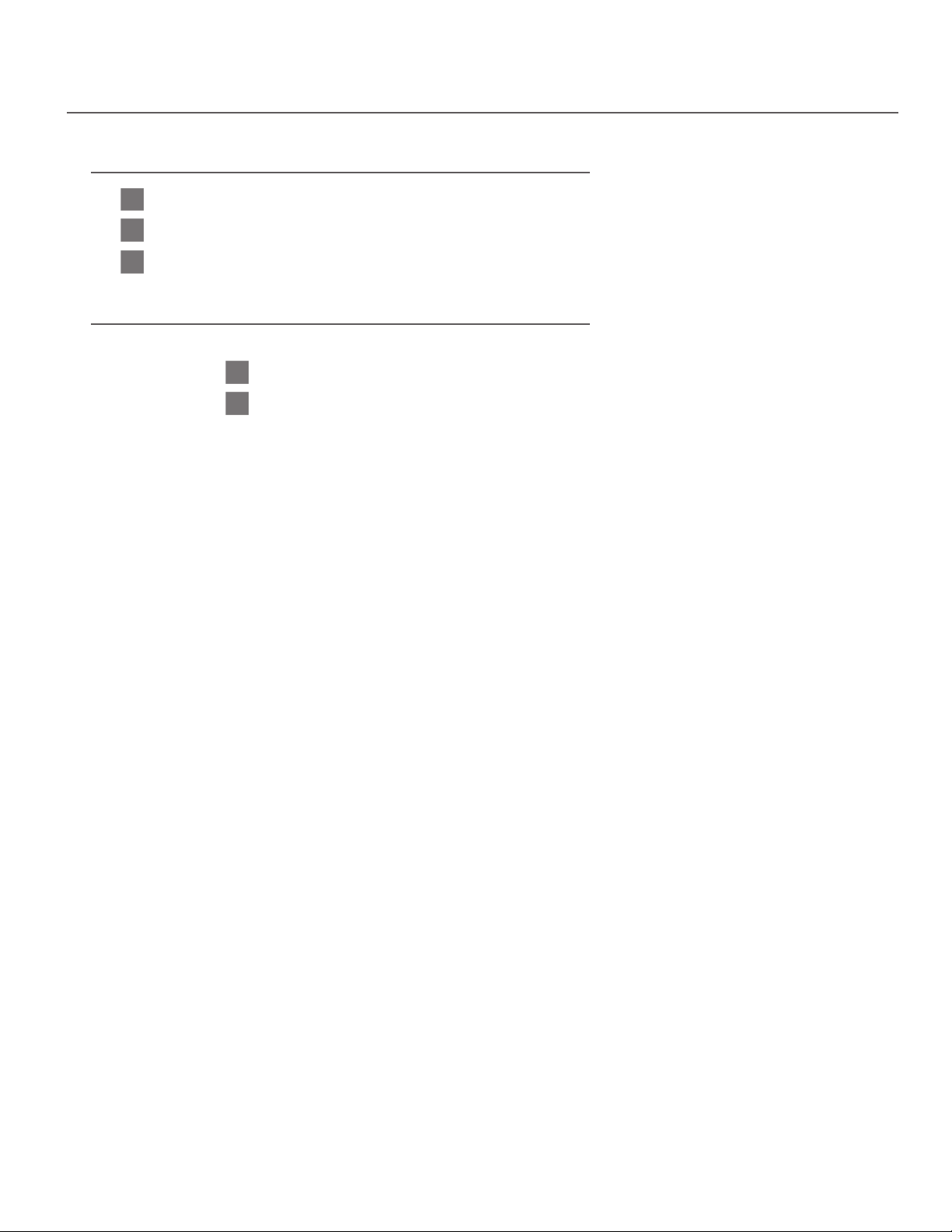
Resetting to Defaults
1
It is possible to reset the unit to factory default settings but the unit must be in the program mode to be reset.
2
While in program mode, select the “Reset to Defaults” function and press the power button.
3
The unit will ash the channel indicator LED’s three times and then shut down when reset.
Exiting Program Mode
There are two ways to exit the program mode
1
Wait 10 seconds without pressing a button (any changes made are saved).
2
Use the Select button to scroll through the program mode functions until the “Exit Program Mode”
function is selected and then press the Power button.
l
23
Page 24
Programming Examples
1
2 3
4
Stereo ModeLED on
1
2 3
4
Stereo ModeLED on
1
2 3
4
1
2 3
4
1
2 3
4
Stereo ModeLED on
Channel Lock-OutLED off
Auto-Seek
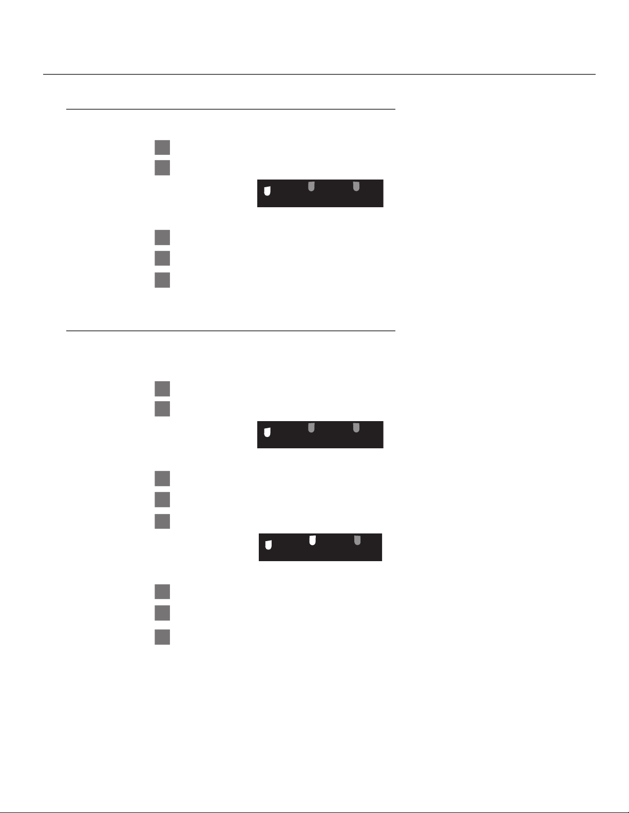
Example #1
I want to turn on/o the Stereo Mode function and then exit program mode
1
Enter Program Mode (see page 19).
2
When program mode is entered the rst function is active and the LED’s will show.
Using the functionality chart on a previous page note that this is the Stereo On/O Function.
3
Note that the channel 4 LED indicates whether or not this function is on/o.
4
Press the power button to turn Stereo Mode on/o.
5
Exit Program Mode.
Example #2
I want to turn on/o the Stereo Mode function and the Auto-Seek Function
and then exit program mode.
1
Enter Program Mode.
2
When program mode is entered the rst function is active and the LED’s will show.
Using the functionality chart on a previous page note that this is the Stereo On/O Function.
3
Note that the channel 4 LED indicator represents whether or not this function is on/o.
4
Press the power button to turn Stereo Mode on/o.
5
Press the Select button two times until the LED’s show.
Using the chart on a previous page note that this is the Auto-Seek Function.
6
Again, note that the channel 4 LED indicates whether this function is on/o.
7
Press the power button to turn Auto-Seek on/o.
8
Exit Program Mode.
24
l
Page 25
Programming Examples
1
2 3
4
Stereo ModeLED on
1
2 3
4
1
2 3
4
1
2 3
4
1
2 3
4
1
2 3
4
1
2 3
4
1
2 3
4
1
2 3
4
1
2 3
4
1
2 3
4
0 (no squelch)
1
2
3
4
5
6
7
8
9
1
2 3
4
Stereo ModeLED on
1
2 3
4
1
2 3
4
1
2 3
4
1
2 3
4
Stereo ModeLED on
Channel Lock-OutLED off
Auto-Seek
Squelch
1
2 3
4
Spare
1
2 3
4
Reset To Defaults
1
2 3
4
1
2 3
4
Stereo ModeLED on
Channel Lock-OutLED off
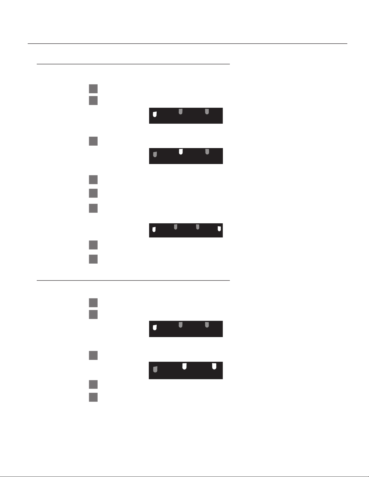
Example #3
I want to lock-out channels 2 and 3 using the Channel Lock-Out Function.
1
Enter Program Mode.
2
When program mode is entered the rst function is active and the LED’s will show.
Using the functionality chart on a previous page note that this is the Stereo On/O Function.
3
Press the Select button once so the LED’s show.
Note that this is the Channel Lock-Out function.
4
Press the Power button to enter the Channel Lock-Out “Sub-Mode”.
5
Upon entry to the Channel Lock-Out “Sub-Mode” the LED’s will show which channels are currently active
(if the unit is at default settings, all four LED’s will be on indicating that all channels are active).
Press the Select button to scroll through the 15 possible combinations of active/locked out channels until
6
the unit displays.
7
Press the Power button to save this setting and return to regular program mode.
8
Exit Program Mode.
Example #4
I want to reset the unit to factory defaults.
1
Enter Program Mode.
2
When program mode is entered the rst function is active and the LED’s will show.
Using the functionality chart on a previous page note that this is the Stereo On/O Function.
3
4
5
Press the Select Button ve times until the unit displays.
Press the Power Button to reset the unit.
The unit will ash the four LED’s three times and then shut down. It will be necessary to manually turn
the unit back on after a reset.
l
25
Page 26
Programming Examples
1
2 3
4
Stereo ModeLED on
1
2 3
4
1
2 3
4
1
2 3
4
1
2 3
4
Stereo ModeLED on
Channel Lock-OutLED off
Auto-Seek
Squelch
1
2 3
4
1
2 3
4
1
2 3
4
1
2 3
4
1
2 3
4
1
2 3
4
0 (no squelch)
1
2
3
4
5
1
2 3
4
1
2 3
4
1
2 3
4
1
2 3
4
1
2 3
4
1
2 3
4
1
2 3
4
1
2 3
4
1
2 3
4
1
2 3
4
1
2 3
4
0 (no squelch)
1
2
3
4
5
6
7
8
9
10
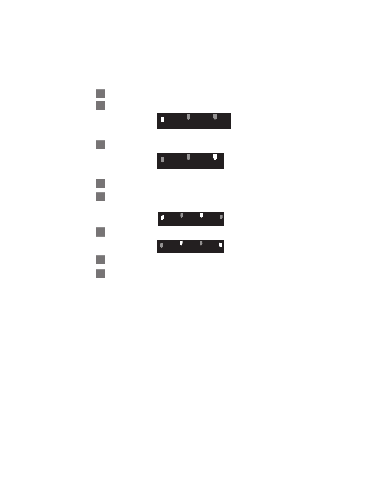
Example #5
I want to tighten the squelch setting to setting 10.
1
Enter Program Mode.
2
When program mode is entered the rst function is active and the LED’s will show.
Using the functionality chart on a previous page note that this is the Stereo On/O Function.
3
Press the Select button three times so the LED’s show
Note that this is the Squelch Adjustment Function.
4
Press the Power button to enter the Squelch Adjustment “Sub-Mode”.
5
Upon entry to the Squelch Adjustment “Sub-Mode” the LED’s will show which squelch setting is
currently selected (if the unit is at default settings, the unit will display representing a squelch setting ve).
6
Press the Select button to scroll through the 16 squelch settings until the unit displays.
7
Press the Power button to save this setting and return to regular program mode.
8
Exit Program Mode
26
l
Page 27

Programmable Features Detailed Descriptions
Stereo Mode (Default is OFF)
Stereo Mode Function
This function must be set to match the type of signal that the receiver is receiving. If the receiver is receiving a
mono signal this function must be OFF. If the receiver is receiving a stereo signal this function must be ON.
When to enable Stereo Mode
Stereo Mode must be enabled if the receiver is receiving a stereo signal from the transmitter.
Channel Lock-Out (Default is All Channels Available)
Channel Lock Out function
This function is used to lock out channels from being accessible to the user when the Select button is
pressed or when the unit is seeking for a channel in Auto-Seek Mode. This function is dierent from
the Channel Lock function in that this function removes channels from being selectable whereas the
Channel Lock function holds the unit on the current channel. By using this program mode you can
lock out any combination of channels.
When to Lock Out Channels
If you have Auto-Seek disabled (default setting), the unit scrolls to the next channel with each press of the
Select button. If, for example, you have a two channel system you can use this feature to “lock out” the other
two unused channels so that the user will not have to scroll through them to get to the channels with a signal.
If you have Auto-Seek enabled and are using less than four channels, you can use the Channel Lock-Out mode
to ensure the receiver will not stop on a channel without a signal. If, for example, you are using Auto-Seek
Mode and have two channels active (channels one and four) and nd that often times when the unit seeks for
channel four is stops on channel three, you would use the Channel Lock-Out Mode to eliminate the problem.
Auto-Seek (Default is O)
Auto-Seek function
Upon power-up with the Auto-Seek feature enabled the unit will search for a channel with a signal present. If a
signal is found the unit will stop and stay on that channel. If the unit does not nd a signal it will continue to seek
until one is found. If the unit is on a channel with a signal it will remain on that channel until the signal is not
detected for a short time at which point it will automatically seek for another channel with signal. If the Select
button is pressed when the unit is on a channel it will seek for the next channel with a signal.
When to Enable Auto-Seek
It is recommended to enable the Auto-Seek feature in applications where a user will be moving from one
area to another and does not want to have to manually change the channel on the receiver in each new area.
Also if it is desired that the Select button act as a “seek” button instead of a manual scroll to the next channel
button, Auto-Seek should be enabled.
Priority
If the receiver has been locked on a channel the lock will take priority over Auto-Seek.
Squelch Setting (Default is 3)
Squelch Setting
The purpose of squelch is to mute the audio output of the receiver when the signal from the radiator(s) is
turned o or is too weak to be received. Without squelch you would hear radio noise in your earphone.
The squelch on your receiver can be adjusted so that it will mute at varying levels of signal strength. There
are 16 settings that the squelch setting can be set to. The lowest squelch setting (no squelch) is “0” and the
tightest squelch setting is “15.” The default setting is “3.”
When to Adjust Squelch Setting
For maximum range the squelch setting should be set to a low level (0, 1, or 2). However, when setting the
squelch level low, the reliability of the squelch setting is compromised and will lead to radio noise being
heard in the earphone when signal strength is low. If no radio noise is desired to be heard, the squelch
setting should be set to a tighter position. However, when setting the squelch level high, the receiver will
have reduced range due to the audio being cut-o when signal is low. See “Programming Unit” section for
instructions on how to adjust squelch setting.
l
27
Page 28
Accessories for LR-42/44
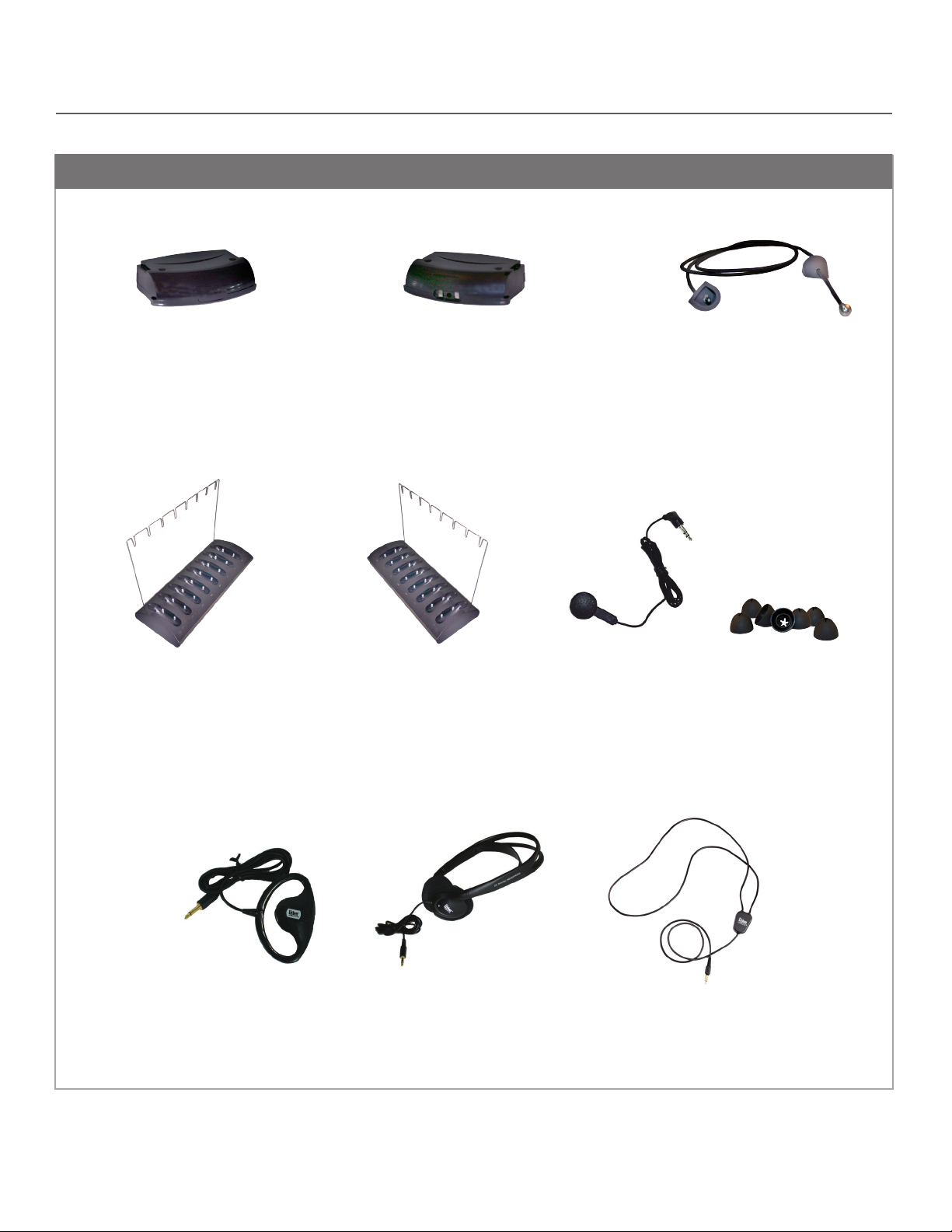
Accessories
LA-152
IR Alkaline battery compartment
included with receiver
LA-350
8-Unit IR Receiver
Charging/Storage Station
LA-364 required
8-Unit IR Receiver Storage Station
LA-364
NIMH Rechargeable Battery Pack
requires LA-350 Charging Station
LA-351
Single Ear Bud
LA-150
Replacement Lanyard for LR-44
LA-161
Replacement Ear Tips
LA-151
(Pkg. of 20)
28
LA-164
Earspeaker
Stereo Headphones
LA-165
LA-166
Neck Loop
l
Page 29
Stationary IR
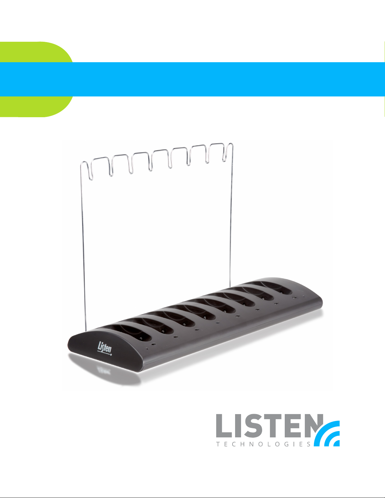
LA-350 8-Unit IR Receiver Charging/Storage Station
LA-351 8-Unit IR Receiver Storage Station
© 2015 Listen Technologies Corporation® All Rights Reserved
For further details regarding use, adjustment, or programming of your Listen Technologies products visit
our website at www.listentech.com/support-manuals or contact us at +1.801.233.8992 or 1.800.330.0891.
l
29
Page 30
LA-350 Package Contents
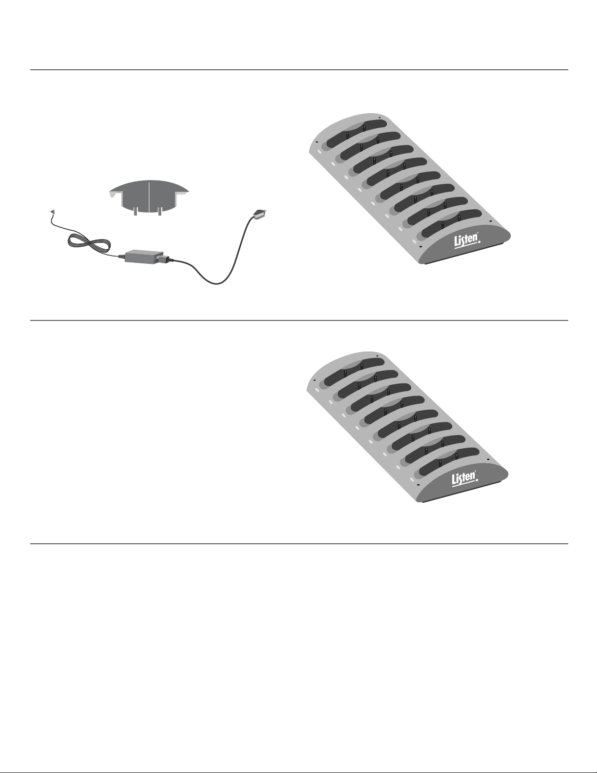
• LA-350 Charging/Storage Station
• LA-204 Power Supply
• Battery Pack Conversion Trays (8)
• Cord Tidy Rack
• LA-350 Quick Reference Card
Battery Pack Conversion Trays
LA-204
LA-351 Package Contents
• LA-351 Storage Station
• Cord Tidy Rack
LA-350
Listen Congurations
• LA-350-01 (North America)
• LA-350-02 (UK)
• LA-350-03 (Euro)
LA-351
30
l
Page 31
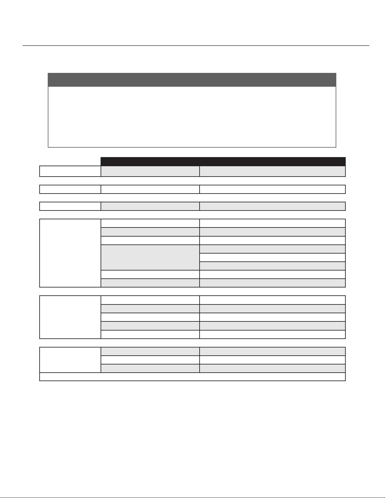
LA-350 Specications
Features
• Can charge or store up to eight LR-42 and/or LR-44 receivers at one time.
• Easy to identify charging: Green LED=fully charged units, Red LED=charging in progress.
• Pockets grab and hold receivers so they will not fall out.
• Charging/Storage Station can be mounted on a at surface or on a wall.
• Can charge battery packs while they are attached to the receiver or while they are
separate from the receiver (by use of included conversion tray).
• Lanyard cords are stored without tangling with use of Cord Tidy Rack.
Specications LA-350
Compliance
Controls User Controls None
Indicators Bicolor LED Red when charging, Green when charging is complete
RF, Safety Compliance FCC, Industry Canada, CE, RoHS
Power Supply
Physical
Environmental
Type In-line switching mode power supply, Listen part number LA-204
Input 100-240 VAC, 47-63 Hz
Output 7.5 VDC, 4 A
North America, Type B, (LA-350-01)
Power Line Cord
Output Connector 5.0mm x 2.1mm Barrel
Compliance UL, CE Listed
Dimensions (H x W x D) 1.50 x 13.60 x 5.40 in. (38 x 345 x 137 mm)
Color Grey with White Silk Screening
Unit Weight 1.2 lbs. (450 g)
Shipping Weight 3.0 lbs. (1.30 kg)
Mounting Options Desk or wall mount
Temperature - Storage -20 C (-4 F) to +50 (122 F)
Temperature - Operation -10 C (14 F) to +40 (104 F)
Humidity 0 to 95% relative humidity, non-condensing
•Specications are subject to change without notication.
Asia, UK, Type G, (LA-350-02)
Euro type J, (LA-350-03)
l
31
Page 32
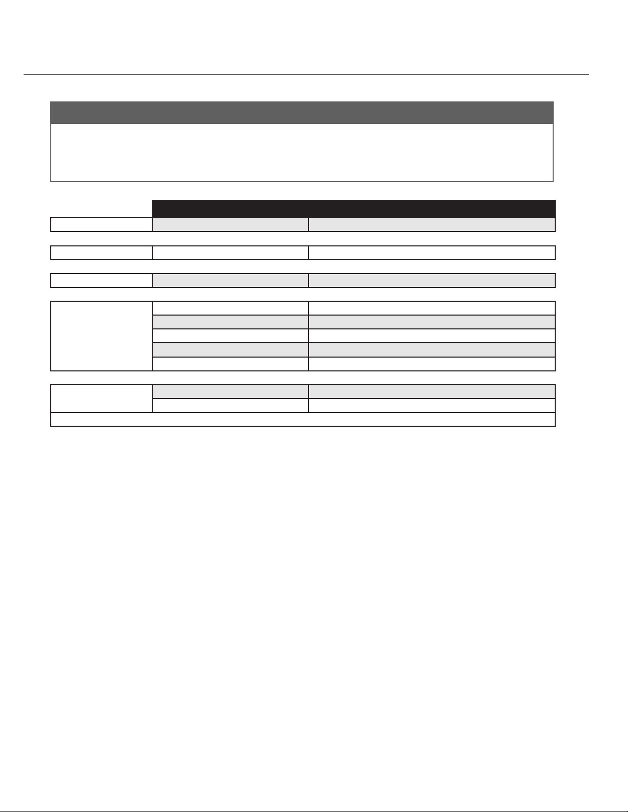
LA-351 Specications
Features
• Can store up to eight LR-42 and/or LR-44 receivers at one time.
• Pockets grab and hold receivers so they will not fall out.
• Storage Station can be mounted on a at surface or on a wall.
• Lanyard cords are stored without tangling with use of Cord Tidy Rack.
Specications LA-351
Compliance Safety Compliance FCC, Industry Canada, CE, RoHS
Controls User Controls None
Power Electrical None
Dimensions (H x W x D) 1.50 x 13.60 x 5.40 in. (38 x 345 x 137 mm)
Color Dark Grey with White Silk Screening
Physical
Unit Weight 0.9 lbs. (400 g)
Shipping Weight 2.6 lbs. (1.10 kg)
Mounting Options Desk or wall mount
Environmental
Temperature - Storage 20 C (-4 F) to +50 (122 F)
Humidity 0 to 95% relative humidity, non-condensing
•Specications are subject to change without notication.
32
l
Page 33
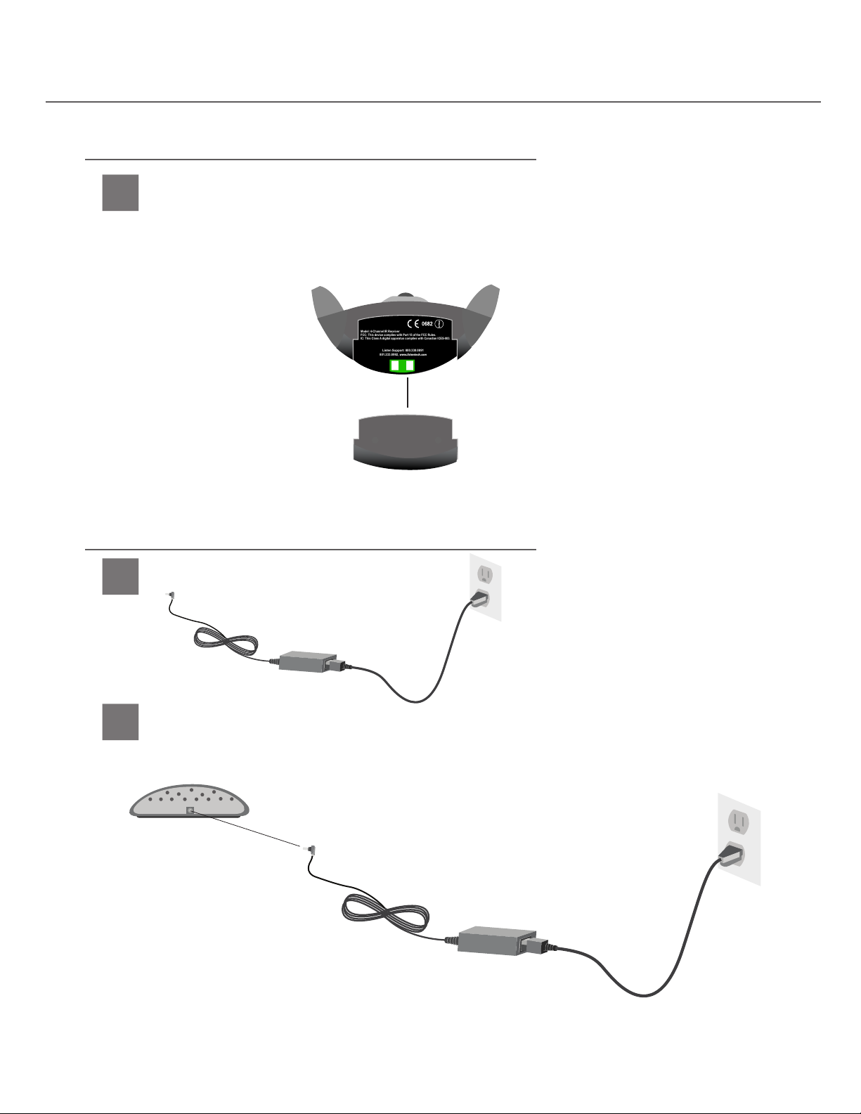
LA-350 Charging Requirements/Instructions
Listen Support: 800.330.0891
801.233.8992, www.listentech.com
Model: 4-Channel IR Receiver
FCC: This device complies with Part 15 of the FCC Rules.
IC: This Class A digital apparatus complies with Canadian ICES-003.
Listen Support: 800.330.0891
801.233.8992, www.listentech.com
Model: 4-Channel IR Receiver
FCC: This device complies with Part 15 of the FCC Rules.
IC: This Class A digital apparatus complies with Canadian ICES-003.
Requirements to Charge Receivers
Requirements to Charge Receivers
1
To charge Listen Technologies LA-42 or LR-44 IR Receiver batteries you must have an LA-364
Rechargeable Battery Pack for each receiver. The LA-350 will not charge AAA NiMH batteries
placed inside the alkaline battery pack that comes with the receiver. The LA-364 battery packs
can be charged while attached to the receiver or they can be charged separate from the receiver.
Charging Instructions
Plug power supply into power source
1
Plug power supply into power source.
Plug power into charging/storage station
2
Plug power into charging/storage station.
l
33
Page 34
1
2 3
4
LA-350 Charging Requirements/Instructions
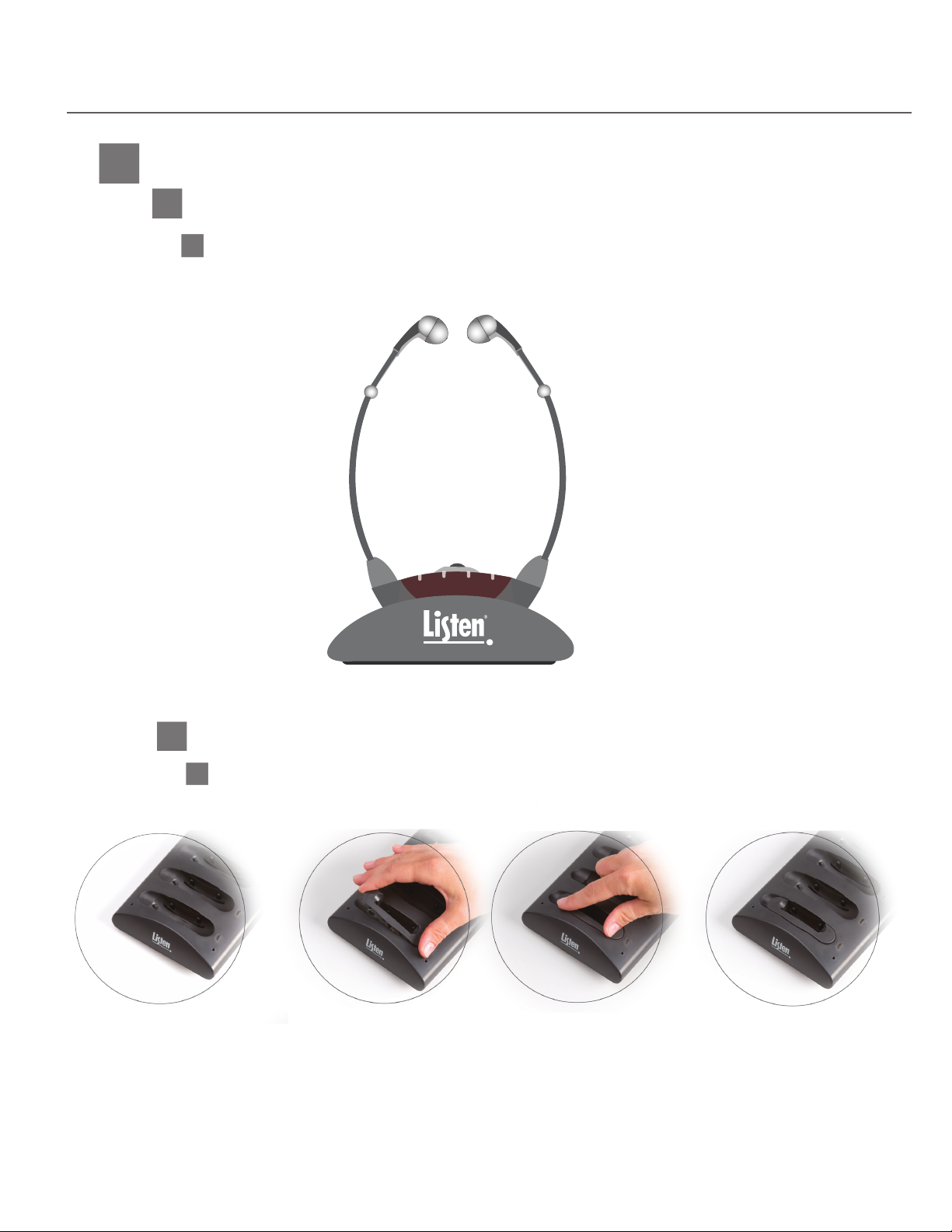
Charging Scheme
3
3A
To Charge Batteries while in Receivers
1
Place receivers in charging slots
Place receivers in charging slots. It may be necessary to press down on the units
to ensure that they are touching the charging contacts.
2 3
1
3B
To Charge Batteries separate from Receivers
1
Install conversion tray
Install conversion tray in slots.
4
34
l
Page 35
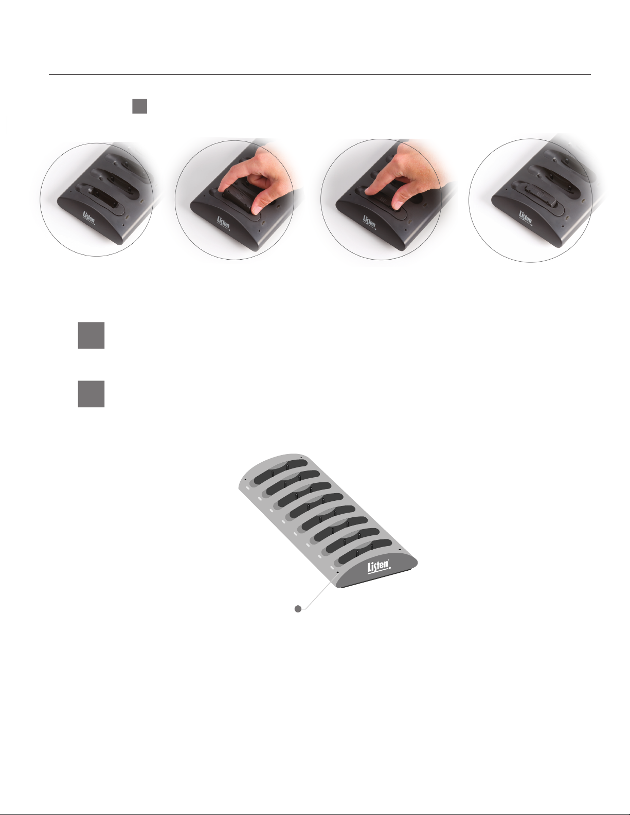
LA-350 Charging Requirements/Instructions
2
Place LA-364 battery packs in converted charging slots
Place LA-364 battery packs in converted charging slots.
Verify batteries are charging
4
Verify batteries are charging. When units begin to charge a red LED will come on near
the charging slot. This LED will stay lit until the receivers are fully charged.
Verify full charge
5
Verify full charge. When the units are fully charged a green LED will come on near the
charging slot. Receivers will charge up to 9 hours for a full battery life.
Red LED=Charging in Process, Green
LED=Charging Complete.
IMPORTANT: When not using your LR-42/LR 44 Receiver it is recommended to keep the
receiver on the charging station. The charging station provides a maintenance charge that
will keep the battery level at 100%. If the receiver is not kept on the charger it can lose
20% of its characters per month.
l
35
Page 36
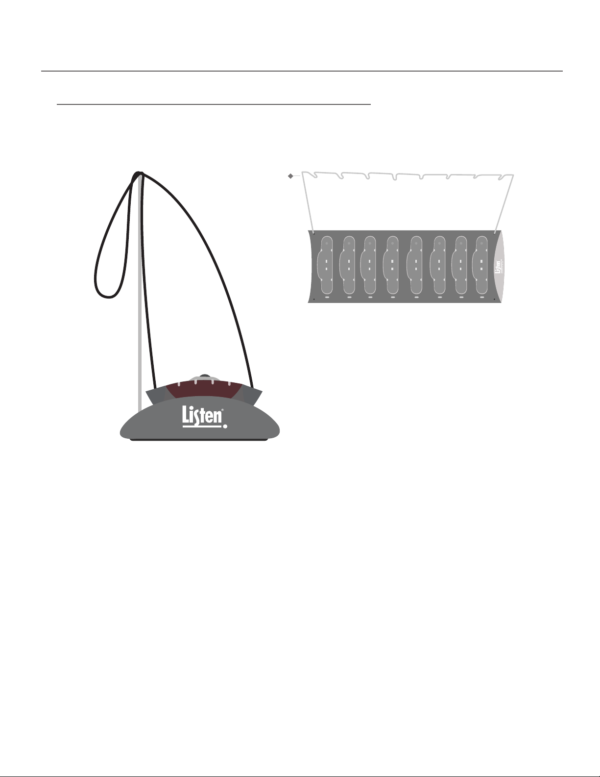
LA-350/351 Cord Tidy Rack
The Cord Tidy Rack
The Cord Tidy Rack can be used, if desired, to help with organizing the lanyard cords of the LR-44
receiver during charging or storage. Insert the tidy rack into the holes on top of the station to use.
Cord Tidy Rack
2 3
1
4
36
l
Page 37

Troubleshooting
Troubleshooting
The audio “drops out” in areas I don’t believe it should.
Audio “drop outs” can occur for several reasons, including the following: The system was set up by trial
and error. With degradation of the IR diodes, the system now has dropouts due to this
reduction in IR output power from the radiator. Make sure to always design the system using the
footprint specications found in the design guide. Also, in a multi-radiator application, the delay switch
settings may be incorrect. The radiators could be out of phase and therefore canceling each other
out. Make sure to set up the delay compensation switch correctly,refer to the Transmitter / Radiator
manual for further information.
The audio sounds distorted in my receivers.
The receiver may be approaching the edge of the coverage pattern where the distortion and noise can
be higher. Also, if the receiver is within 10 feet of the radiator it can cause the receiver to be saturated
with IR. It is a good idea to have a minimum distance of 10 feet from any radiator.
I turn up the volume wheel all the way on my receiver but the audio level is still too low.
Make sure that the Input level and Transmit Level is adjusted appropriately on the transmitter.
Low batteries in the receiver will also cause low output volume.
There is a tone in the audio.
Make sure the test tone button on the transmitter is OFF. Also, make sure that two transmitters are
not on the same channel in a multi-channel system.
I cannot change the channel on my receiver.
If when you attempt to change the channel, the channel indicator LED only ashes but does not
change channel, the receiver is locked on the current channel. See page 18 for information on unlocking the unit.
I cannot get my receiver to scroll to the channel I want to use.
There are two reasons why the receiver would not scroll to the channel you want the unit to be on.
The rst is that the unit is in “Auto-Seek” mode and is not nding a signal on the channel you are trying
to tune the unit to. See page 19 for more information about Auto-Seek mode. The second is that the
unit is programmed to not tune to the channel you are trying to tune it to. Refer to page 19 for more
information about channel programming.
The batteries are not charging in my receivers.
Make sure that you have an LA-364 NiMH battery pack installed on the receiver and that the
charger is plugged in.
l
37
Page 38
Frequently Asked Questions
Frequently Asked Questions
Can I make my receiver change channels automatically if I enter a room with a signal present on a
Q
dierent channel?
Yes. In Auto-Seek Mode the receiver will automatically nd an active channel. If the unit
A
squelches or the select button is pressed, the unit will automatically search for an active
channel. Refer to page 19 for more information about Auto-Seek Mode.
How do I check the battery level on my receivers?
Q
When the unit is on, press the power button momentarily. The LEDs will display the battery
A
status for three seconds (4 LEDs: 75-100%, etc.). See page 16 for more information.
How do I adjust the squelch setting on my receiver?
Q
See page 22 for detailed instructions on adjusting the squelch setting.
A
How can I tell if the receiver has been fully charged when using the LA-350?
Q
The green LED to the side of charging pocket will illuminate.
A
Can I use rechargeable batteries in the alkaline battery compartment?
Q
No. You must purchase a Listen Technologies LA-364 NiMH battery pack if you want to use
A
a charging case.
My rechargeable batteries don’t last very long. Why?
Q
If your batteries have been through many charging cycles they may need to be replaced.
A
38
l
Page 39
Compliance, Warranty and Contact Information
Compliance Information
The following compliance information applies to the LT-82, LA-140-GY, LA-140-WH, LR-42, LR-44 and LA-350.
This device complies with Part 15 of the FCC Rules. Operation is subject to the following two conditions: (1) This device may not
cause harmful interference, and (2) this device must accept any interference received, including interference that may cause
undesired operation.
This Class A digital apparatus complies with Canadian ICES-003.
These devices are RoHS compliant.
Warranty
Listen Technologies Corporation (Listen) warrants its transmitters and receivers (LT-82, LT-700, LT-800, LR-100, LR-42,
LR-44, LR-300, LR-400, LR-500, LR-600) to be free from defects in workmanship and material under normal use and conditions
for the useful lifetime of the product from date of purchase.
Listen warrants its Stationary IR Radiators (LA-140) to be free from defects in workmanship and material under normal use and
conditions for three years from the date of purchase.
Listen warrants its Noise Canceling Microphone (LA-270) to be free from defects in workmanship and material under normal use
and conditions for one year from date of purchase.
Listen warrants its Charging/Carrying Cases (LA-306, LA-311, LA-313, LA-317, LA-318, LA-319, LA-320, LA-321, LA-322, LA-323,
LA-324, LA-325, LA-350) to be free from defects in workmanship and material under normal use and conditions for one year
from date of purchase.
All other products and accessories are warranted for 90 days from date of purchase.
This warranty is only available to the original end purchaser of the product and cannot be transferred. Warranty is only valid
if warranty card has been returned within 90 days of purchase. This warranty is void if damage occurred because of misuse or
if the product has been repaired or modied by anyone other than a factory authorized service technician. Warranty does not
cover normal wear and tear on the product or any other physical damage unless the damage was the result of a manufacturing
defect. Listen is not liable for consequential damages due to any failure of equipment to perform as intended. Listen shall bear
no responsibility or obligation with respect to the manner of use of any equipment sold by it. Listen specically disclaims and
negates any warranty of merchantability or tness of use of such equipment including, without limitation, any warranty that the
use of such equipment for any purpose will comply with applicable laws and regulations. The terms of the warranty are governed by the laws of the state of Utah.
In the rst ninety days after purchase, any defective product will be replaced with a new unit. After 90 days, Listen will, at its own
discretion either repair or replace transmitters and receivers with a new unit or a unit of similar type and condition. Product that
is not covered under warranty shall be repaired or replaced with a unit of similar type and condition based on a at fee. Contact
Listen for details.
This limited warranty, prices and the specications of products are subject to change without notice.
Contacting Listen
If technical service is needed, please contact Listen. Pre-authorization is required before returning Listen
products. If products were damaged in shipment, please contact the carrier, then contact Listen for
replacement or repair requirements payable by the carrier.
Listen’s corporate headquarters are located in Bluffdale, Utah U.S.A. and are open Monday through Friday,
8am to 5pm Mountain Time.
14912 Heritage Crest Way
Bluffdale, Utah 84065-4818
+1.801.233.8992
+1.800.330.0891 North America
+1.801.233.8995 fax
www.listentech.com
l
39
Page 40

40
Listen Technologies Corporation
14912 Heritage Crest Way
Bludale, Utah 84065-4818, U.S.A.
+1.801.233.8992
+1.800.330.0891
+1.801.233.8995
North America
fax
www.listentech.com
Printed in the United States of America
© 2015 Listen Technologies Corporation
®
All Rights Reserved 20150709
l
Page 41

l
41
 Loading...