

Page 1
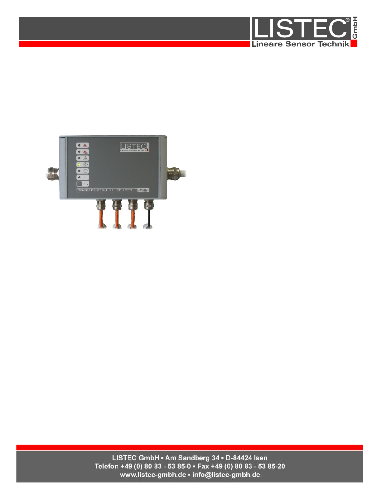
SCU 800
d-LIST Control Unit
The sensor control unit SCU 800 is the central
supervisory element for the d-LIST-system. It provides
up to two d-LIST sensor cables with power, performs
the cyclic addressing of the connected sensors every
10 seconds, acquires the temperature values
measured by each sensor and evaluates the data with
reference to various criteria.
A fire alarm is generated if either a given maximum
threshold is exceeded, or if an increase in temperature
takes place within a certain time (differential
evaluation). The two thresholds (set-points) can be set
individually for each of the attached sensor cables.
The measurement resolution of 0,1° gives the system a high sensitivity. The tried and tested algorithms used in
the evaluation eliminate false alarms due to natural temperature variations.
Alarms are indicated by LEDs on the front-panel and via floating contacts to a fire terminal station (fire control
panel), host computers or other transmission systems. Hereby, alarms generated by the two sensor cables are
signalled individually.
Resetting takes place via an external signal from the fire terminal station or by pressing the front-panel mounted
reset button.
The serial RS-232 interface can be used for programming and setting of system parameters. LISTEC® GmbH
offers the terminal software LISTterm 8 for this purpose.
For the visualisation of the system status, message- and temperature-lists, as well as a graphic display of the
temperature and alarm data, LISTgraph II and the Data Management Unit DMU 600 is available.
A LIST®controller can be used to connect and control several SCU 800 from a central point via a RS-485
interface.
1/2
60V041-06/ 02.12.13
Page 2

General:
Collective display (LED's) for
Fire cable A
Fire cable B
Fault
Operation
Temperature measurement
Data transmission
Alarm criteria
Alarming due to the exceeding of an absolute- or a
differential-threshold (set-point). All thresholds are
individually settable for each sensor cable.
For both alarm criteria a pre-alarm can be set in the
range between 10 to 90% of the alarm thresholds.
Fault recognition
Sensor cable faults, such as the malfunctioning of a
sensor or a cable break, are recognised and
indicated within one measuring cycle, generally
within 10 seconds. Faults in the control unit are
registered in the internal message list and are
signalled immediately.
Interface
RS-232 Serial-interface for programming
parameters and interrogation of system data.
Optionally a RS-485 interface.
Connections
All connections take place inside the unit via
terminals.
The RS-232 interface, 9 pin D-Sub female, is
accessible once the unit is opened.
System specifications:
Number of measuring points
Max. 99 sensors per cable connection
Sensor cable length
Max. overall length of the sensor cable, including
connection cables is 250 m.
The sensor cable may consist of separate cable
pieces
Delivery extent:
CD with data sheet, operation manual, description
of commands and system messages, installation
guidelines
Serie 800
SCU800/3 Item number: G00231 SCU800/16 Item number: G00233
Continuous operating temperature: -10°C .. +60°C
Dimensions: 260 x 150 x 90 mm
Power supply: 21 – 29 V
DC
Housing material: aluminium
Power consumption: 21 – 29 V
DC
Weight: 1,9 kg Weight: 2,3 kg
Power consumption: (normal use) 1,9 W Power consumption: (normal use) 2,7 W
Outputs:
Floating change-over contacts with space for user defined supervisory
resistors:
Fire alarm 2 relays (1 per cable)
Fault alarm 1 relay (fail safe)
Outputs:
Floating change-over contacts with space for user defined supervisory
resistors:
Fire alarm 16 zonal relays
Fault alarm 1 relay (fail safe)
Switching voltage: 48 VDC / 32 V
AC
max.
Switching current: 250 mA max. (ohmsche Last)
Input: 5 VDC reset input, galvanically isolated
2/2
60V041-06/ 02.12.13
 Loading...