

Page 1
ig
OPERATING MANUAL
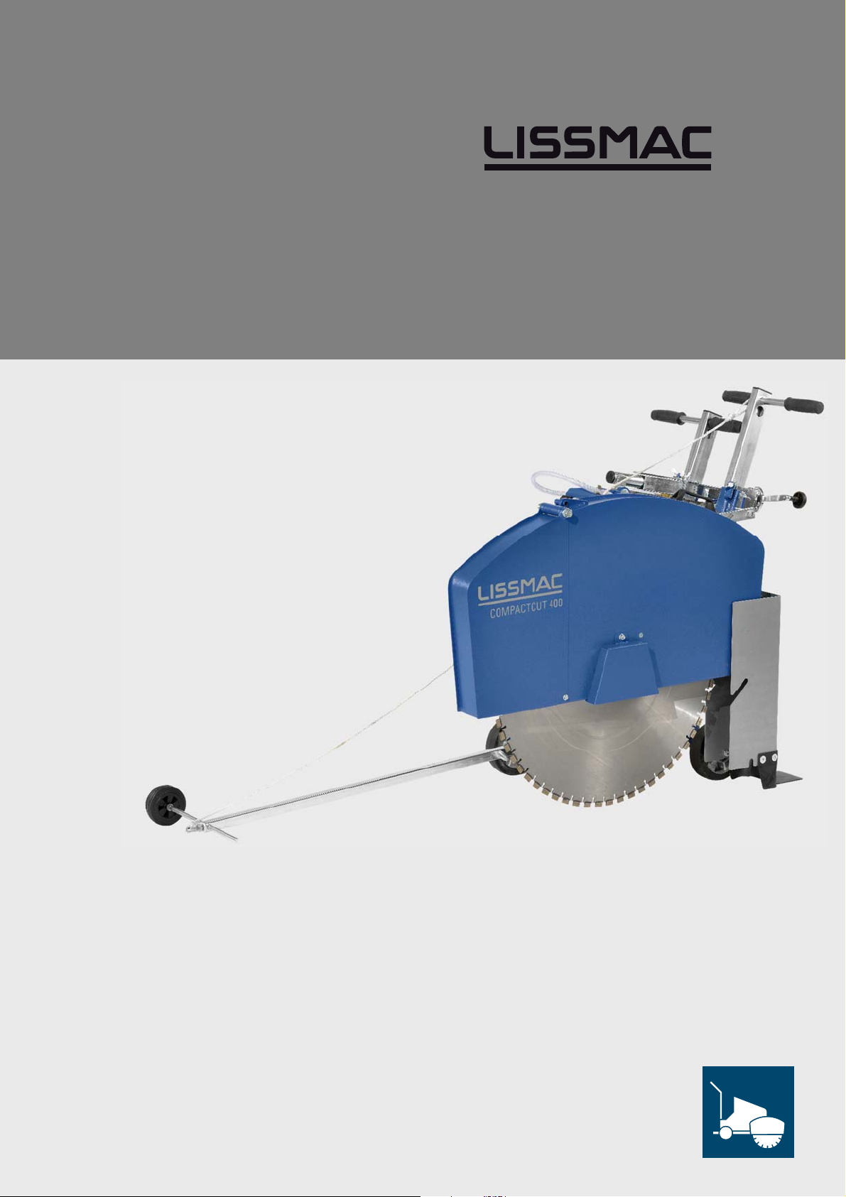
FLOOR SAW
COMPACTCUT 400 E
CONSTRUCTION TECHNOLOGY
LISSMAC Maschinenbau GmbH
Lanzstrasse 4
D-88410 Bad Wurzach
Telephone +49 (0) 7564 / 307- 0
Fax +49 (0) 7564 / 307 - 500
[email protected]
www.lissmac.com
1
Page 2

2/45
Page 3

Imprint The operating manual is valid for:
LISSMAC floor saw
• COMPACTCUT 400 E
Company headquarters:
LISSMAC Maschinenbau GmbH
Lanzstraße 4
D - 88410 Bad Wurzach
Phone: +49 (0) 7564 / 307 – 0
Fax: +49 (0) 7564 / 307 – 500
Translation of the original operating manual
Status: 08-2016
The dissemination or duplication of this operating manual in any form, or the reuse of contents is
forbidden unless permitted in writing.
Non-compliance is subject to compensation for damages. All rights reserved for the purpose of
patent, utility model, or design patent registration.
3
Page 4
BASIC SAFETY INSTRUCTIONS
Warning notices and symbols in this operating manual
Danger!
Caution!
Note Indicates that failure to comply leads to damage to the machine or other property.
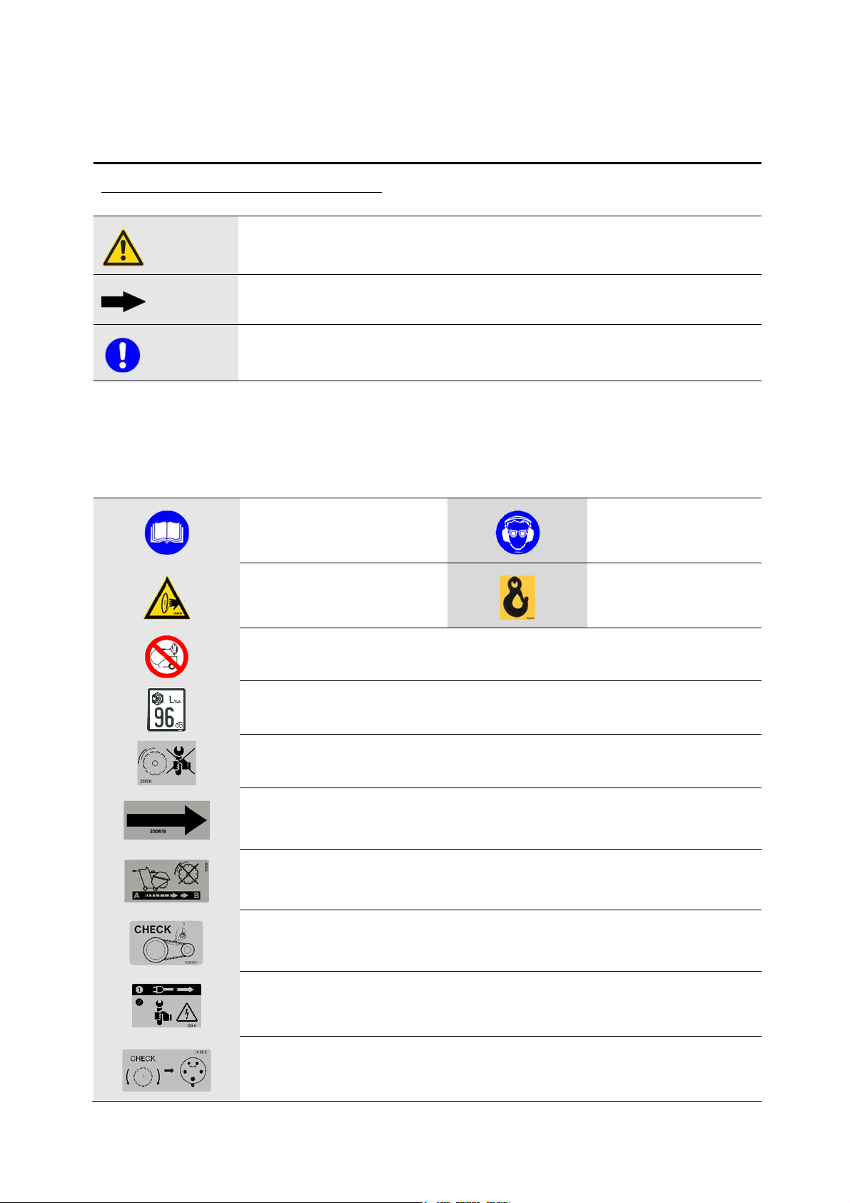
The following warning and safety symbols were attached on the machine:
Indicates that failure to comply could lead to severe injury or even death.
Indicates that failure to comply could sometimes lead to injuries.
Handling information for operators
The defined sequence of the handling steps makes proper and safe handling of the machine easier.
• Handling instructions for the operator
Observe the operating manual
Warning due to rotating saw blade
Wear safety glasses and hearing
protection
Attachment point for crane
transport
High-pressure washing prohibited
Noise power level (noise level) of the machine
Working on the saw blade protective hood is prohibited when the saw blade is running.
Running direction of sawblade
The machine must not be moved when the sawblade is running
Check the drive belts
Disconnect from the power supply during maintenance or when removing the protective hood
Check the running direction, change the phase sequence
4/45
Page 5

OPERATING MANUAL
Preface This operating manual should make it easier to get to know the machine and make use of
its intended applications.
The operating manual contains important information on how to operate the machine
safely, properly and economically. Your close attention helps avoid risk, repair costs and
downtime, and increase the reliability and lifetime of the machine.
The operating manual is to be supplemented by directives for accident prevention and
environmental protection, according to applicable national requirements.
The operating manual is to be kept permanently available at the machine location.
The operating manual must be read and used by each person assigned to work with the
machine, e.g.:
• Operating, including tooling, troubleshooting during operating, correction of
production rejects, service, disposal of operating and auxiliary materials
• Maintenance (service, inspection, repair) and/or
• Transport.
Along with the operating manual and the valid legal regulations for accident prevention in
the country of use and the place of use, also recognised regulations for safety and proper
work are to be observed.
Required tool In order for the floor saw to be operated, a tool - in the form of a saw blade - is required.
These tools can be purchased from the manufacturer.
Changes and reservations
We attempt for this operating manual to be correct and up-to-date. To maintain our
technological lead, it can be necessary to change the product without advance notice and
to perform their operation. We accept no liability for malfunctions, breakdowns and
damage caused by this.
5
Page 6

Notes:
6/45
Page 7

Table of Contents
1. Description of performance .................................................................................................. 8
1.1. Basics of intended use ......................................................................................................... 9
1.2. Organisational measures ..................................................................................................... 9
1.3. Personnel choice and personnel qualification; basic responsibilities .............................. 10
1.4. Safety instructions for operation phases .......................................................................... 11
1.4.1. Transport, assembly and installation ....................................................................... 11
1.4.2. Commissioning .......................................................................................................... 11
1.4.3. Operation ................................................................................................................... 12
1.4.4. Cutting with an open saw blade protective hood. ................................................... 12
1.4.5. Special work while using the machine ..................................................................... 13
1.4.6. Moving the floor saw ................................................................................................ 13
1.5. Safety instructions for special types of dangers ............................................................... 13
1.5.1. Danger for the operator by the machine .................................................................. 13
1.5.2. Electric power ........................................................................................................... 14
1.5.3. Dust ........................................................................................................................... 14
1.5.4. Noise ......................................................................................................................... 14
1.6. Transport ............................................................................................................................ 14
1.7. Packaging and Storage ...................................................................................................... 15
1.8. Environmental protection ................................................................................................... 15
1.9. Disposal .............................................................................................................................. 15
2. Description of the device ..................................................................................................... 16
2.1. Name of machine parts ...................................................................................................... 16
2.2. Safety guards ..................................................................................................................... 16
2.3. Technical data .................................................................................................................... 17
2.4. Noise power level .............................................................................................................. 17
2.5. Hand arm vibration ............................................................................................................. 18
2.6. Water pressure................................................................................................................... 18
3. Commissioning ...................................................................................................................... 19
3.1. Connections and operating materials ................................................................................ 19
3.2. Tool selection ..................................................................................................................... 19
3.3. Parking brake ...................................................................................................................... 19
3.4. Install saw blade ................................................................................................................ 20
3.5. Changing saw blade direction ........................................................................................... 21
3.6. Drive belt ............................................................................................................................ 22
4. Transport ................................................................................................................................ 23
4.1. Transport position .............................................................................................................. 23
4.2. Move with the crane .......................................................................................................... 23
4.3. Disassembling the machine ............................................................................................... 24
5. Operation ................................................................................................................................ 25
5.1. Safety ................................................................................................................................. 25
5.2. Preparations for starting .................................................................................................... 25
5.3. Moving or setting up the floor saw ................................................................................... 25
5.4. Cutting with the floor saw ................................................................................................. 26
5.5. Cutting with an open saw blade protective hood. ............................................................ 26
5.6. Wall gliding saw hood (optional) ....................................................................................... 27
5.7. Turning of floor saw ........................................................................................................... 27
6. Maintenance .......................................................................................................................... 28
6.1. Service ................................................................................................................................ 28
6.2. Troubleshooting table ........................................................................................................ 29
6.3. Torque of screw connections ............................................................................................. 30
6.4. Maintenance plan .............................................................................................................. 31
7. Tools ........................................................................................................................................ 32
8. Conditional connections ...................................................................................................... 33
9. Warranty ................................................................................................................................ 34
10. Replacement parts .............................................................................................................. 35
7/45
Page 8
1. DESCRIPTION OF PERFORMANCE
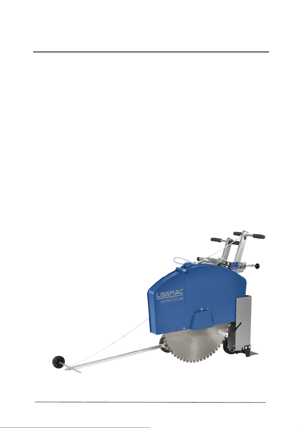
Thanks to optimum weight distribution of the COMPACTCUT 400 E, the 7.5 kW/ 400 V electrical
motor ensures an exceptional cutting performance.
• Every corner of the building site can be reached thanks to the compact, easy to handle design
• LISSMAC electrical floor saws are low noise and therefore are particularly suited for cutting
work in and on buildings
• The COMPACTCUT 400 E is fast and can be simply dismantled into three pieces. This means
it can be easily transported inside buildings
• Lowering and raising the saw blade is done smoothly by means of an threaded spindle with
cutting depth display, thereby preventing damage to the saw blade
• Optimum speed of the saw blade shaft
• Saw hood front can be raised for intersections
• Patented flush to wall sawing system with 800 mm wall gliding saw hood (optional) with
flush to wall saw blade holder. Floor cutting flush to walls conforming to the current machine
guidelines or C-standard is guaranteed!
• Exceptional directional stability from the central saw arm position
• The permanently horizontally positioned saw hood offers optimum accident protection and
minimizes spray water loading
• Height adjustable handles
• Easily converted from left to right cut with few hand movements
• The rear running wheel sits outside of the saw cut. This makes recutting of cut joints easy
• Standard flange spraying ensures low water consumption and optimal cooling
• A high slot and saw accuracy is reached due to the optimal weight distribution on the front
wheels
8/45
Page 9
1.1. Basics of intended use
1.1.1 The warranty obligation of the manufacturer and supplier is voided for improper or non-intended
use. Any change to the machine which is not carried out by the manufacturer is prohibited.
Changes, removal or addition of parts to the floor saw only with the written approval of the
manufacturer.
1.1.2 The machine is constructed according to the state of the art and recognised technical safety rules.
However, danger to life and limb of the user or third parties, and/or damage to the machine or other
property may still arise from its use.
1.1.3 Only use the machine in technically faultless condition and for intended use, aware of safety and
danger complying with the operating manual. You should particularly handle malfunctions which
can compromise safety immediately, or have them addressed by experts.
1.1.4 The LISSMAC floor saw is a floor cutting grinder and is designed exclusively for cutting grooves into
concrete or asphalt using water. Cutting uses saw blades and the machine may only be operated for
cutting of floors. The floor saw may only be operated by one person and is limited by proper
positioning at the rear part of the floor saw. Any other use or use above and beyond is not
considered intended use.
Intended use also includes compliance with the operating manual and observance of inspection and
maintenance manual.
1.1.5 Foreseeable misuse / non-intended use:
Cutting without saw blade protective hood
Cutting without water
1.2. Organisational measures
1.2.1 The operating manual must be easily accessible for each person at the location of the floor saw.
1.2.2 All additions to the operating manual, all generally valid legal and otherwise binding regulations for
accident prevention and environmental protection are to be followed and instructed!
Such obligations may also apply, for example, to the handling of hazardous materials or the wearing
of personal protective gear or traffic regulations.
1.2.3 Personnel assigned to activities on the floor saw must have read and understood the operating
manual, particularly the Safety Instructions chapter, before starting work. In the middle of work it is
too late. This particularly applies to personnel only occasionally engaged with the crane, such as
those involved in tooling and maintenance.
1.2.4 At least occasionally, perform checks for safe and hazard awareness work by operators while
following the operating manual!
Cutting of wood, plastic or metal (except for reinforcement in concrete).
Building changes, which alter the safety or the floor saw design type.
9/45
Page 10
1.2.5 Use personal protection equipment if necessary or required by regulations!
1.2.6 Keep all safety instructions and danger warnings on the floor saw and in legible condition! Replace
safety and danger instructions, that are damaged or non-readable any more.
1.2.7 For safety-related changes to the machine or its running behaviour, stop the machine immediately
and mark it accordingly. Report the problem to the responsible post/person!
1.2.8 No changes, removal or addition of parts without the written approval of the manufacturer! The
instructions of the tool maker must be followed.
1.2.9 Only use tested original replacement parts from the manufacturer!
1.2.10 Observe required or prescribed deadlines given in the operating manual for inspection.
1.2.11 Workshop equipment suitable for the work is absolutely necessary for performing maintenance
actions.
1.3. Personnel choice and personnel qualification; basic responsibilities
1.3.1 Only qualified personnel 18 years of age or older may operate the floor saw independently. All
personnel must be trained in the operation and be explicitly, in writing, authorized by the company
to operate the floor saw.
1.3.2 Establish responsibilities of the personnel for operating, changeover, servicing, and repairing the
machine!
1.3.3 Make sure that only authorized personnel works at the machine.
1.3.4 The operator must wear personal safety equipment according to the safety regulations, such as
safety shoes, safety gloves and safety glasses.
1.3.5 Remaining in the working area of the floor saw unnecessarily is prohibited! Direct unauthorised
personnel, who are not working on the machine, away from the work area. Block off the working
area, if necessary.
1.3.6 During all movement of the floor saw, operating personnel must ensure that they and other people
are not endangered. All obstacles which may hinder the operation or implementation of the
machine at the location of use must be moved out of the way.
1.3.7 Work on the electrical equipment of the machine may only be carried out by qualified electricians or
trained personnel under the management and supervision of a qualified electrician, and in
accordance with the rules of electronics.
1.3.8 Any personnel training, learning, being instructed, or currently involved in general education may
only work with the machine under the continual supervision of an experienced person!
10/45
Page 11
1.4. Safety instructions for operation phases
1.4.1. Transport, assembly and installation
1.4.2. Commissioning
1.4.1.1 Transport, assembly and installation on/with the floor saw may only be carried out in transport
position. Secure the floor saw against rolling away.
1.4.1.2 Transport, assembly and installation on/with the floor saw may only be carried out with removed
saw blade and when the drive motor is turned off.
1.4.1.3 The transport the floor saw in compliance with the maximum operating weight, this should be
exclusively done by crane.
1.4.1.4 The transport may only be done, as long as all machine parts are tightened on the machine and
individual parts cannot fall.
1.4.2.1 The commissioning of the floor saw may only be carried out in transport position.
1.4.2.2 When inserting the saw blade, observe the running direction. The cutting process must always be
done clockwise, otherwise material is ripped out which causes small pieces of debris to fly around.
1.4.2.3 When inserting the saw blade, protect against sharp edges.
1.4.2.4 Ensure that the floor on which cuts are to be made fulfils load carrying capacities.. All obstacles
must be cleared away from the cutting area and make sure there is sufficient lighting.
1.4.2.5 Visual inspection of the whole floor saw for damages and defects. Special check of the safety
1.4.2.6 The steering rod must be set for the operator.
1.4.2.7 Keep water sources handy for cooling the saw blade.
1.4.2.8 No rotating tools which have a maximum rotation speed smaller than the nominal speed of the
equipment.
machine can be used.
Defective or broken tools must be replaced immediately.
11/45
Page 12
1.4.3. Operation
1.4.4. Cutting with an open saw blade protective hood.
1.4.3.1 Refrain from working in any manner that is questionable in regard to safety!
1.4.3.2 Take measures to ensure that the floor saw is operated only in a safe, functional condition!
1.4.3.3 The floor saw must be checked at least once per shift for externally identifiable defects or
damages! Any changes which occur (including operating behaviour) must be reported immediately
to the responsible post/person! If necessary, immediately stop the machine and secure it against
restart!
1.4.3.4 Immediately stop and secure the floor saw in case of malfunctions! Immediately correct
malfunctions! Electrical work may only be carried out by qualified electricians.
1.4.3.5 Only suitable and tested tools must be used.
1.4.3.6 For protection before acceleration, move the depth setting of the saw blade slowly into the solid
floor. Avoid any contact with the running tool.
1.4.3.7 It is prohibited to cut without the saw blade protective hood or the drive motor cover. The operator
must be protected by turning parts.
1.4.4.1 Removing or opening of the saw blade protective hood or reaching into the saw blade during
1.4.4.2 When cutting with an opened saw blade protective hood folded open the saw blade does not
cutting is prohibited. This work may only be carried out with the saw blade at a standstill and the
drive motor turned off.
cover the front area. Particular care is necessary!
12/45
Page 13
1.4.5. Special work while using the machine
1.4.6. Moving the floor saw
1.4.5.1 Follow all setup, maintenance, and inspection activities and schedules prescribed by the operating
manual, including all information about the replacement of parts / assemblies! These activities
may only be carried out by technical personnel.
1.4.5.2 Inform operating personnel before beginning special and maintenance work! Name a supervisor!
1.4.5.3 If the floor saw is turned off during maintenance and repair work, it must be secured against
unexpected application of power.
1.4.5.4 Before cleaning all openings in which no cleaning agent should penetrate due to safety and/or
functional reasons must be covered and glued. Electric motors, switches and plugs are especially
at risk. After cleaning, remove the covers/tape completely!
1.4.5.6 During service and repair work, always tighten loose bolt joints!
1.4.7.7 If dismantling is required for fitting, servicing and repair, the safety fittings must be remounted
and checked immediately following the service and repair work!
1.4.7.8 No rotating tools which have a maximum rotation speed smaller than the nominal speed of the
machine can be used.
1.4.6.1 The floor saw may only be moved when the saw blade is at a standstill.
1.4.6.2 Before leaving the operating position on the floor saw, the drive motor must be shut down and the
saw blade must no longer rotate.
There is a danger of injury by a rotating saw blade.
1.4.6.3 The operator may not leave the floor saw if the parking brake has not been activated. The floor
saw must be secured against rolling away.
1.5. Safety instructions for special types of dangers
1.5.1. Danger for the operator by the machine
1.5.1.1 Before leaving the operating position on the floor saw, the drive motor must be shut down and the
saw blade must no longer rotate.
There is a danger of injury on a rotating saw blade.
1.5.1.2 Working on the floor saw and moving with rotating saw blade is prohibited.
1.5.1.3 The drive motor of the floor saw must only be put in operation for intended use cutting.
13/45
Page 14
1.5.2. Electric power
1.5.3. Dust
1.5.4. Noise
1.5.2.1 Use only original fuses with the specified current rating! In case of malfunctions, turn the floor
saw off immediately! Electrical work may only be carried out by technical and qualified personnel.
1.5.2.2 Carry out maintenance or repair work only when the motor of the floor saw is turned off and the
saw blade is not running any more. Transport position requires special care.
1.5.2.3 The machine's electrical equipment must be inspected/checked regularly. Faults such as loose
connections or damaged cables must be corrected immediately. The machine must be labeled so
that it cannot be started by others.
1.5.3.1 When working in close quarters, follow any applicable national guidelines!
15.3.2 To prevent dust build-up during cutting, the saw blade must be cooled using water. Dry cutting is
prohibited and damages not only the saw blade.
1.5.4.1 See 2.4 Noise power level of the machine
1.6. Transport
1.6.1 To implement using a crane, slinging equipment with sufficient load carrying capacity must be
1.6.2 Name expert instructors for the lifting process!
1.6.3 Lift the floor saw only according to the instructions in the operating manual and with proper lifting
1.6.4 Only use suitable transport vehicle with sufficient load capacity!
1.6.5 Secure loads reliably according to the regulations. Use suitable attachment points!
1.6.6 Even when moving only for a short distance, the motor of the floor saw must be turned off. The
1.6.7 When recommissioning, follow the operating manual!
used. Slinging equipment must be checked for damage before use.
gear!
saw blade may not be rotating before a restart!
14/45
Page 15
1.7. Packaging and Storage
To ensure sufficient protection during shipping and transport, the machine and its components are
In the case of damage, the machine must not be put into operation. Even damaged cable and plugs
If the machine is not immediately put into operation after unpacking, it must be protected from
1.8. Environmental protection
Packaging material, cleaning agents, used or residual operating materials, as well as removed
1.9. Disposal
carefully packaged. When receiving the machine, the machine should be checked for damage. The
packaging of the device consists of materials which can be recycled. Put these by type into the
relevant recycling containers, so that they can be recycled properly.
represent a safety risk and must not be used. In this case, please contact the manufacturer.
moisture and dirt.
wear parts, such as drive belts or motor oils must be taken to recycling corresponding to the valid
regulations for environmental protection at the place of use.
If the expiry date of the device has been reached, in particular if functional errors happen, make
the used machine unusable.
Dispose of the device according to the valid regulations for environmental protection of your
country. Electrical waste may not be disposed of in household waste. Take the used device to a
central rubbish collection centre.
15/45
Page 16
2. DESCRIPTION OF THE DEVICE
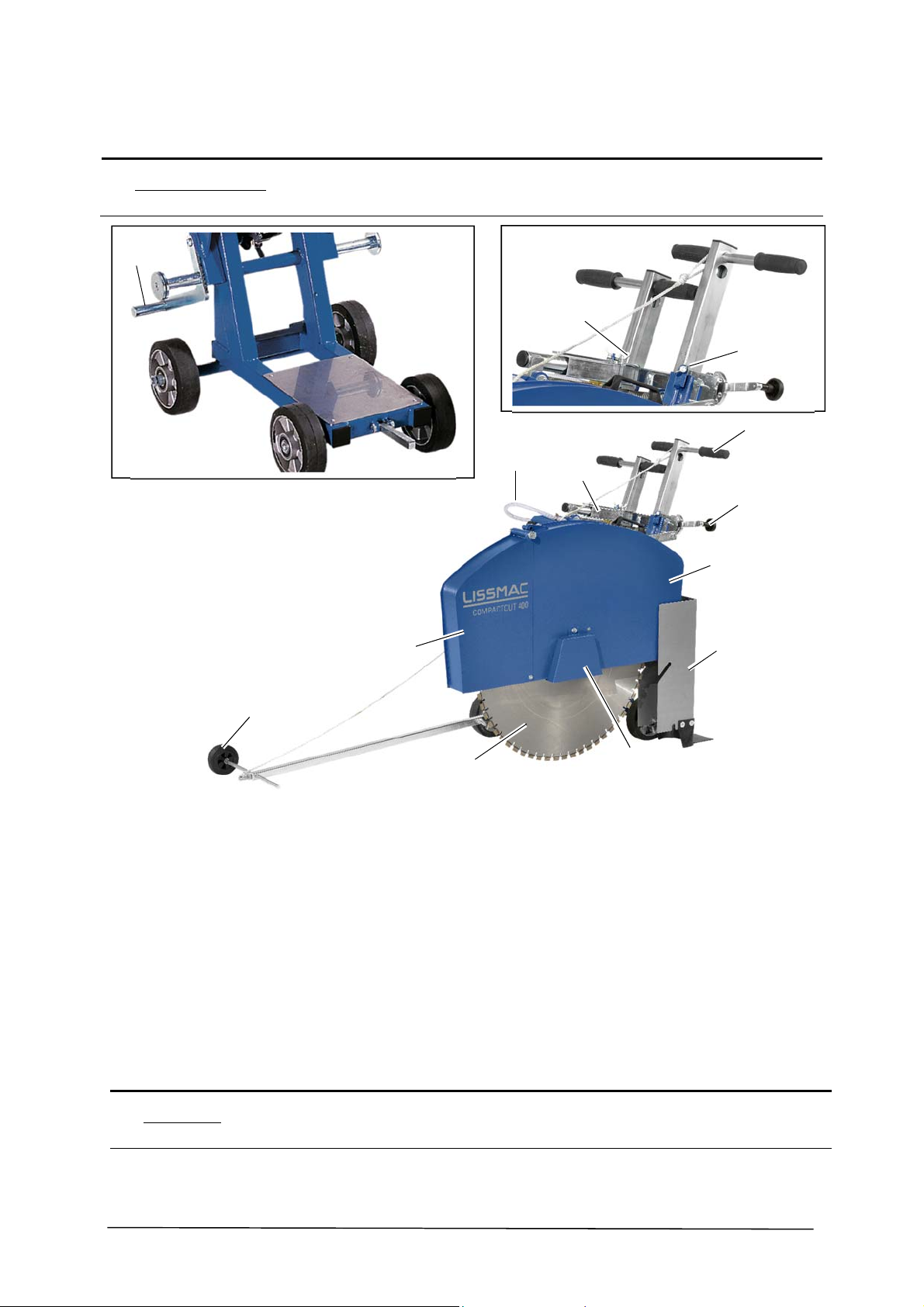
2
2.1. Name of machine parts
11
12
13
3
1
4
5
10
6
9
8
Pos. 1 Water hose Pos. 8 Saw blade
Pos. 2 Saw arm Pos. 9 Steering rod
Pos. 3 Handle Pos. 10 Fold up part of the saw blade protective hood
Pos. 4 Handle (height adjustment) Pos. 11 Parking brake
Pos. 5 Saw blade protective hood Pos. 12 Thumb screw for table foot adjustment
Pos. 6 Spray protection Pos. 13 Thumb screw for the handle
Pos. 7 Flange cover of the saw blade protective hood
7
2.2. Safety guards
Pos. 5 Pos. 6 Spray protection
16/45
Page 17
2.3. Technical data
COMPACTCUT 400 E
Max. cutting depth 320 mm
Max. saw blade diameter 800 mm
Saw blade holder 25.4 mm
Saw blade speed 1250 1/min
Operating weight 167 kg
Left/right cut yes
Drive motor Electric motor
Power consumption 400V / 16.1 A
Power supply 3PH + N + PE
Power (kW/PS) 7.5 kW
Dimensions (min.) L/W/H 1200 / 650 / 1090 mm
2.4. Noise power level
Danger!
In an environment with a high noise level, for example when working near loud machinery,
wearing hearing protection in the workplace is prescribed for above 85 dB(A).
The details define volume of noise level, related to the operator workspace and the noise power
level of the floor saw.
The measured noise level L
The emission noise pressure at the operator's place L
The guaranteed noise power level is:
COMPACTCUT 400 E 96 dB(A)
The values are determined by the noise emission measurement.
Testing is done under load with the largest permitted saw blade of the floor saw.
Measurement tolerances:
2.5 dB for the A-value noise power level
4 dB for the A-value emission noise pressure level
Emission noise pressure is done in compliance with
EN ISO 3744, EN 13862 and guidelines 2000/14/EC.
95 dB(A)
wA
96 dB(A)
pA
17/45
Page 18

2.5. Hand arm vibration
The given value was determined with the maximum saw blade diameter.
The impact can be reversely proportional to the weight of the operator.
Total vibration value:
The following standards were complied with during measurement:
EN ISO 5349, VD 2057 Sheet 2, Directive 2002/42/EC.
The given values were measured during concrete cutting at a cut depth of 5 cm.
In practice, these values are influenced by the following conditions:
• Quality of the saw blade
• Number of saw blades
• Weight of the operator
• Feed speed
• Condition of the machine
• Concrete properties
COMPACTCUT 400 E aHV less than 2.5 m/s2
2.6. Water pressure
Note
The water pressure in the lines to the floor saw must not exceed 5 bar. Otherwise use a pressure
reducer and reduce the water pressure to max. 5 bar.
18/45
Page 19
3. COMMISSIONING
3.1. Connections and operating materials
3.2. Tool selection
Danger!
Connection of electricity
A reliable power source with an operating voltage and corresponding fuses as shown on the
model plate must be available.
Water spray
To prevent dust build-up during cutting, the saw blade must always be cooled using water. Dry
cutting is prohibited!
Lubrication points
Moving parts must be lubricated on the lubrication points of the floor saw at regular intervals.
The manufacturer uses a qualified heat-resistant multi-purpose grease.
The use of non-tested or unauthorised tools such as cutting wheels or circular saw blades is
prohibited. Damaged tools must not be used!
All tools in the area of diamond tools are marked in colours. Depending on the application
purpose and area, tools are different. To have the best results, the parameters must match.
Storage of tools
Tools must be protected against humidity during storage. The applied segments around the saw
blade must be protected from damage.
Note
3.3. Parking brake
Danger!
In the LISSMAC sales booklet, the prices for the tools are determined. This sales booklet can be
obtained from the manufacturer at any time.
In order to secure the floor saw against rolling away, the parking brake must be used.
The parking brake is set via the height adjustment of the saw arm.
Loosen the spring lock on the crank and turn it into the upper position
The parking brake presses on the wheel of the floor saw and prevents it from rolling
away
Secure the height adjustment via the spring lock
19/45
Page 20
3.4. Install saw blade
Danger!
Removing or opening of the saw blade protective hood or reaching into the rotating saw blade
during cutting is prohibited. These works may only be carried out with the saw blade at a
standstill and the drive motor turned off.
1
2
Note
Note
No rotating tools which have a maximum rotation speed smaller than the nominal speed of the
machine can be used.
Defective or broken tools must be replaced immediately.
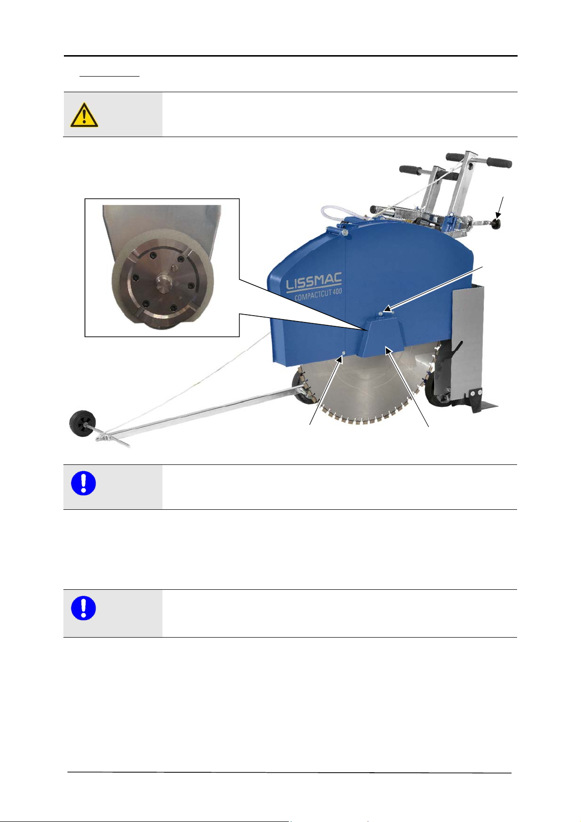
In order to change the saw blade, the following steps must be carried out:
When installing the saw blade, ensure that the flange surfaces are clean. The saw blade must sit
directly on the flange. Match the direction of rotation of the saw blade with the rotation direction
arrow (synchronised sawing) on the saw blade protective hood.
3
Rotate the saw arm to the uppermost position above the crank (Pos. 1)
Remove the hexagon head screw (Pos. 2)
Remove the flange nuts using the tool kit (SW36) and remove the pressure disc
Insert saw blade
Install the pressure disc and flange nut
Insert the locking pin
Remove the flange nuts using the tool kit (SW36) and remove the pressure disc
4
20/45
Plug-in the saw blade protective hood
Page 21
3.5. Changing saw blade direction
Danger!
Removing or opening of the saw blade protective hood or reaching into the rotating saw blade
during cutting is prohibited. These works may only be carried out with the saw blade at a
standstill and the drive motor turned off.
1
5
2
4
Note
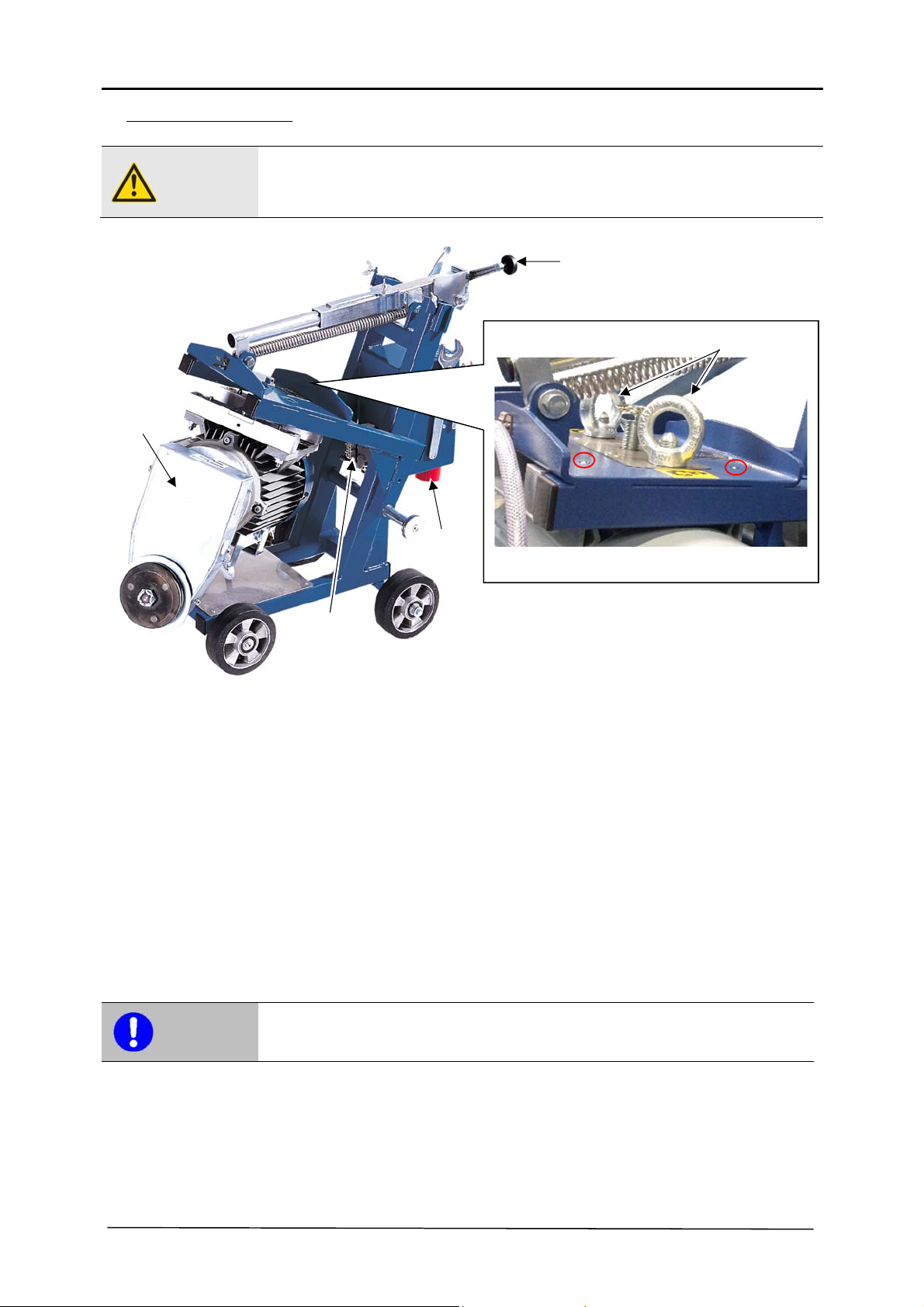
In order to change the saw blade direction, the following steps must be carried out:
The saw head (Pos. 2) must be secured using the ring screws after turning.
3
Disconnect the floor saw from mains power (Pos. 4) and unplug the connection plug
between the electrical motor and the plug housing (Pos. 3)
Disconnect the water hose
Remove the saw blade protective hood and rods from the floor saw
Remove the saw blade from the floor saw (see Section 3.4)
Rotate the saw arm downwards above the hand crank (Pos. 1)
(Set the saw blade fixture on the floor)
Remove ring screws (Pos. 5)
Rotate the saw arm upwards above the hand crank (Pos. 1)
The saw head releases downwards and can be turned to the other side
Insert saw blade
Install the pressure disc and flange nut
Insert the saw blade - protective hood and replace the rods
21/45
Page 22
3.6. Drive belt
3
1
Danger!
Removing or opening of the saw blade protective hood or reaching into the rotating saw blade
during cutting is prohibited. These works may only be carried out with the saw blade at a
standstill and the drive motor turned off.
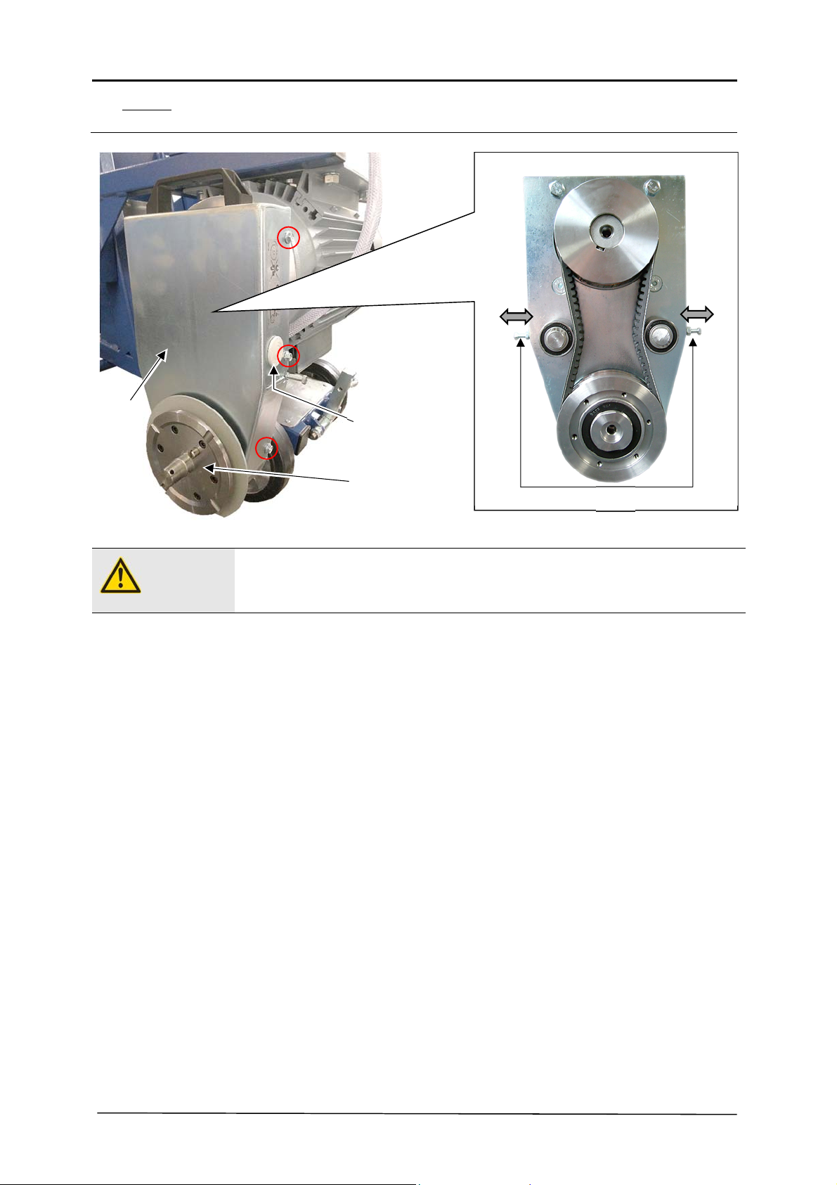
Inspection
Inspection of the drive belts can be done by pushing them with the thumbs.
The effects of an improperly tensioned drive belt:
Inserting and removal or re-tensioning the drive belts
2
4
Remove the cover (Pos. 3)
Inspection by pushing them with the thumbs
Drive belt too loose:
Drive belt slips on the v-belt pulley, no or low power transmission
Drive belt tightened too much:
Excessive wear, much heating of the v-belt pulley with resulting damage
Remove the saw blade protective hood and rods from the floor saw
Remove the saw blade from the floor saw (see Section 3.4)
Remove the saw blade flange (Pos. 2)
Remove the drive motor cover (Pos. 1)
By loosening the safety screw (Pos. 4), drive belts can be released or tightened
The drive belts can be removed
22/45
Page 23
4. TRANSPORT
4.1. Transport position
Danger!
Note
In order to secure the floor saw against rolling away, the floor saw may only be transported in
transport position.
When transporting the floor saw, unintentional position changes must be prevented. Motor oil can
leak into the combustion area of the motor and damage it.
The transport position includes:
4.2. Move with the crane
Danger!
The floor saw may only be transported or moved in transport position.
Parking brake is actuated, the saw arm is in the uppermost position and interlocked using
the spring lock
Saw blade is removed, to avoid damage to the saw blade.
Drive motor is turned off
The steering rod to the machine is folded away
Push the steering handle into the frame
Danger!
Only use undamaged slinging equipment with sufficient carrying capacity.
Personnel should never remain under hanging loads.
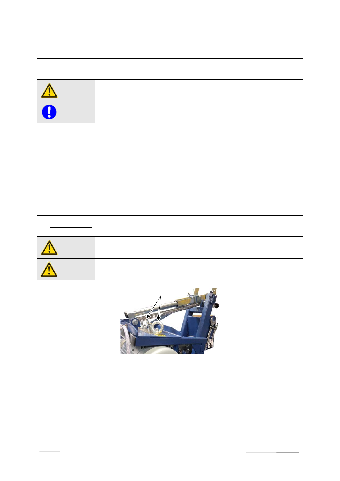
Hang the floor saw with slinging equipment with sufficient load carrying capacity on the ring
screws (Pos. 1).
1
Name expert instructors before the lifting process
Only use suitable transport vehicle with sufficient load capacity
Lift carefully and pay attention to the centre of gravity
Always keep an eye on the floor saw
Secure loads reliably. Use suitable attachment points
When recommissioning, follow the operating manual
23/45
Page 24
4.3. Disassembling the machine
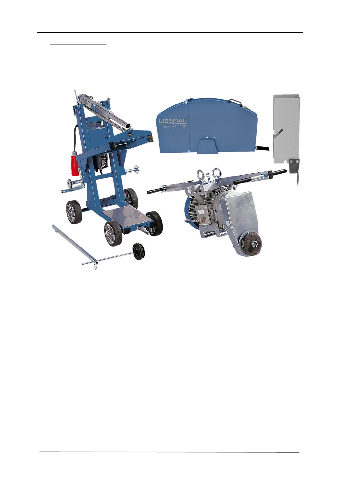
The floor saw can be dismantled into individual parts with a few movements for transport,
relocating or storage.
24/45
Page 25
5. OPERATION
5.1. Safety
Danger!
Danger!
5.2. Preparations for starting
Danger!
Note
The operator authorized to cut must introduce feed movement using the handle. Standing is
limited to this area of the floor saw. The floor saw may only be operated by one person. Inform
people to keep away from the cutting area, or block it off.
Removing or opening of the saw blade protective hood or reaching into the rotating saw blade
during cutting is prohibited. These works may only be carried out with the saw blade at a
standstill and the drive motor turned off.
Ensure that the floor on which cuts are to be made fulfils load carrying capacities.. All obstacles
must be cleared away from the cutting area and make sure there is sufficient lighting.
The cut area can be labelled using a marking spray to orient the operator for cutting.
To be able to use the floor saw safely and properly, the following pre-requisites must be fulfilled:
Check the floor saw for damages, loose screw connections and completeness of the
attaching parts.
5.3. Moving or setting up the floor saw
Danger!
Danger of injury from rotating saw blade!
When moving the floor saw the saw blade must not be rotating.
Moving the floor saw must first be done if
During moving the parking brake must be released. During this the operator must not leave the
intended position of the floor saw. The parking brake must be activated again immediately after
positioning!
A water connection must be available
A suitable saw blade, which meets the optimal conditions, must be mounted
The water cooling system must be functional
Secure power supply must be available
• the drive motor is turned off and the saw blade no longer rotates
• the parking brake is activated
25/45
Page 26
5.4. Cutting with the floor saw
Danger!
The floor saw may only be put into operation, if all starting preparations (see 5.2) are met. If this
is not possible, the operation of the floor saw is prohibited. Dry cutting without water is
prohibited!
Put the floor saw in position
Fold the steering rod downwards
Open the ball valve on the water tap
Start the drive motor:
To start up place the main switch of the saw blade to the "Star" position.
Once the motor has reached the maximum speed, place the main switch on the "Triangle"
position.
Introduce feed movement via the steering handle
Adjust the feed speed to the feed force
5.5. Cutting with an open saw blade protective hood.
Danger!
Removing or opening of the saw blade protective hood or reaching into the rotating saw blade
during cutting is prohibited. These works may only be carried out with the saw blade at a
standstill and the drive motor turned off.
Danger!
When cutting with an opened saw blade protective hood folded open the saw blade does not
cover the front area. Particular care is necessary!
1
2
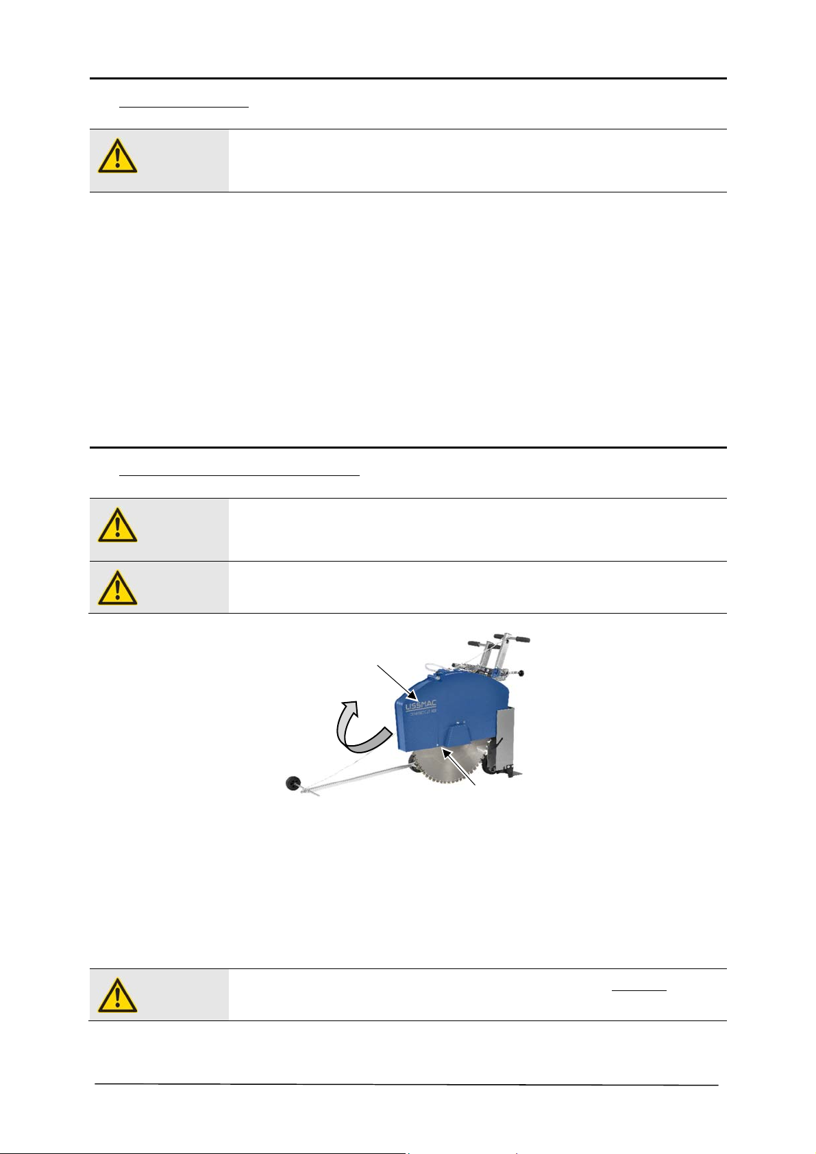
The saw blade protective hood front on the floor saw can be raised.
This function is required to cut wall corners open.
Turn off drive motor and wait until the saw blade is not running anymore
Loosen the screws on the side of the saw blade protective hood (Pos. 2)
Fold the saw blade protective hood upwards (Pos. 1)
Tighten the screws for safety
26/45
Danger!
After cutting, the saw blade protective hood (Pos. 1) must be closed again immediately! Turn off
drive motor and wait until the saw blade is not running anymore.
Page 27
5.6. Wall gliding saw hood (optional)
Danger!
Danger!
Removing or opening of the saw blade protective hood or reaching into the rotating saw blade
during cutting is prohibited. These works may only be carried out with the saw blade at a
standstill and the drive motor turned off.
Cutting with an open saw blade protective hood is prohibited! Ensure that the saw blade
conforms to standards - is covered.
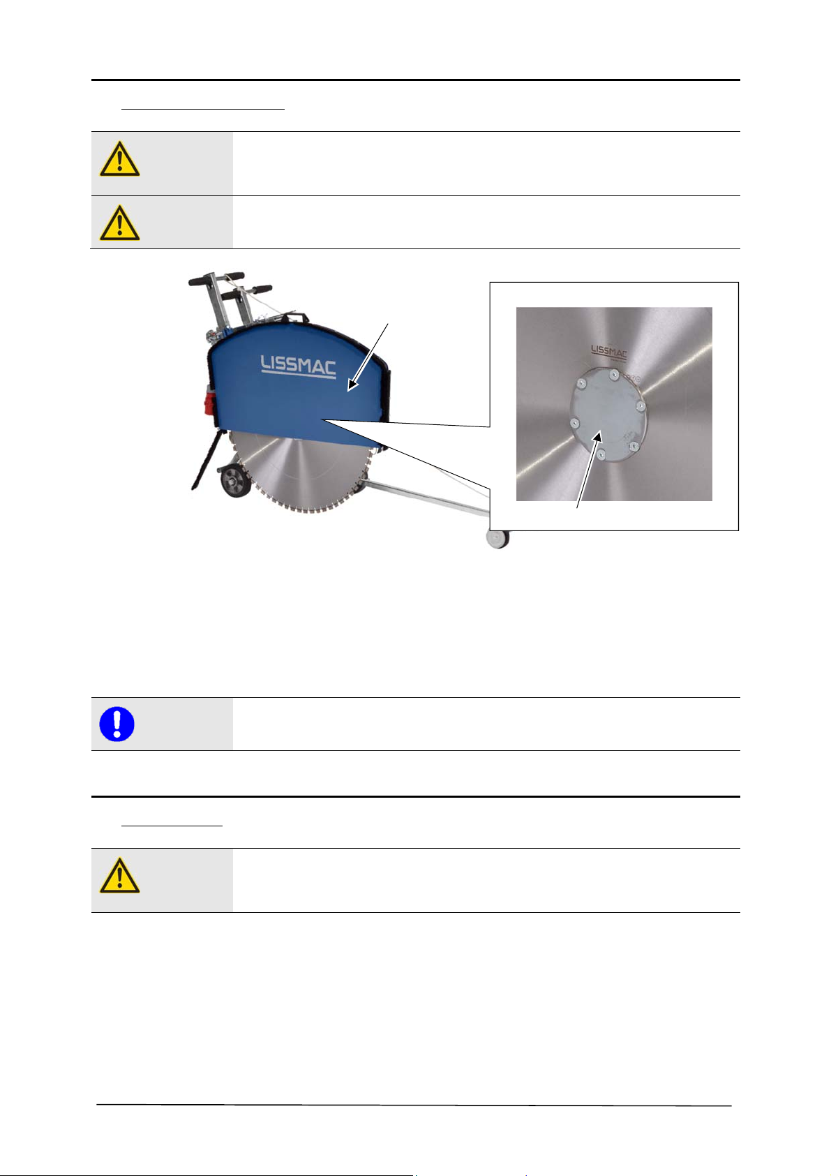
1
The saw blade protective hood on the floor saw can be exchanged for a wall sliding saw hood
(optional). This wall gliding saw hood (Pos. 1) permits cutting with the floor saw flush to a wall.
2
Note
5.7. Turning of floor saw
Danger!
Turn off drive motor and wait until the saw blade is not running anymore
Remove the saw blade protective hood from the floor saw
Mount the wall gliding saw hood and rods on the floor saw
A special flange (Pos. 2) is required for cutting flush to a wall
Before leaving the operating position on the floor saw, the drive motor must be shut down and the
saw blade must no longer rotate.
There is a danger of injury by a rotating saw blade.
Remove the saw blade with the handle from the cut groove
Move the rotary switch from the "Triangle" position to "Off"
Turn the main switch off.
Disconnect the power supply
Move the saw blade protective hood upwards until the parking brake actuates
27/45
Page 28
6. MAINTENANCE
6.1. Service
Danger!
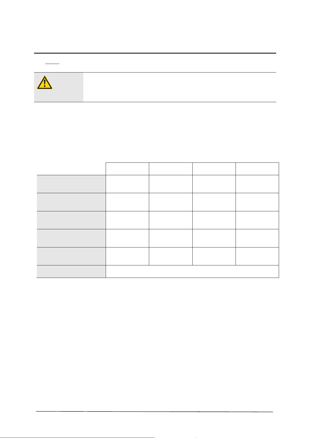
Visual inspection for recognisable
damage and deficiencies
Clean the floor saw thoroughly
(depending on use)
Check the V-belt saw blade drive
Maintenance and repair works must only be carried out by qualified personnel. The floor saw must
be secured against turning on by other people. The saw blade protective hood may only be
removed when the saw blade is at a standstill. Maintenance and repair works may only be carried
out when the machine is turned off.
Cleaning
To protect painted surfaces no aggressive cleaning agents may be used.
Lubrication
Use only high-quality grease which meets the specifications on lubrication nipples. The lubricant
used for the floor saw is called "Energrease LS2 BP“.
Before each use
Daily Weekly Monthly
Lubricate the cutting depth adjustment
spindle with spray grease
Spring lock - lubricate the cutting
depth adjustment (lubrication nipple)
Screw connections Retighten all screw connections after 20 operating hours see 6.3
28/45
Page 29
6.2. Troubleshooting table
Danger!
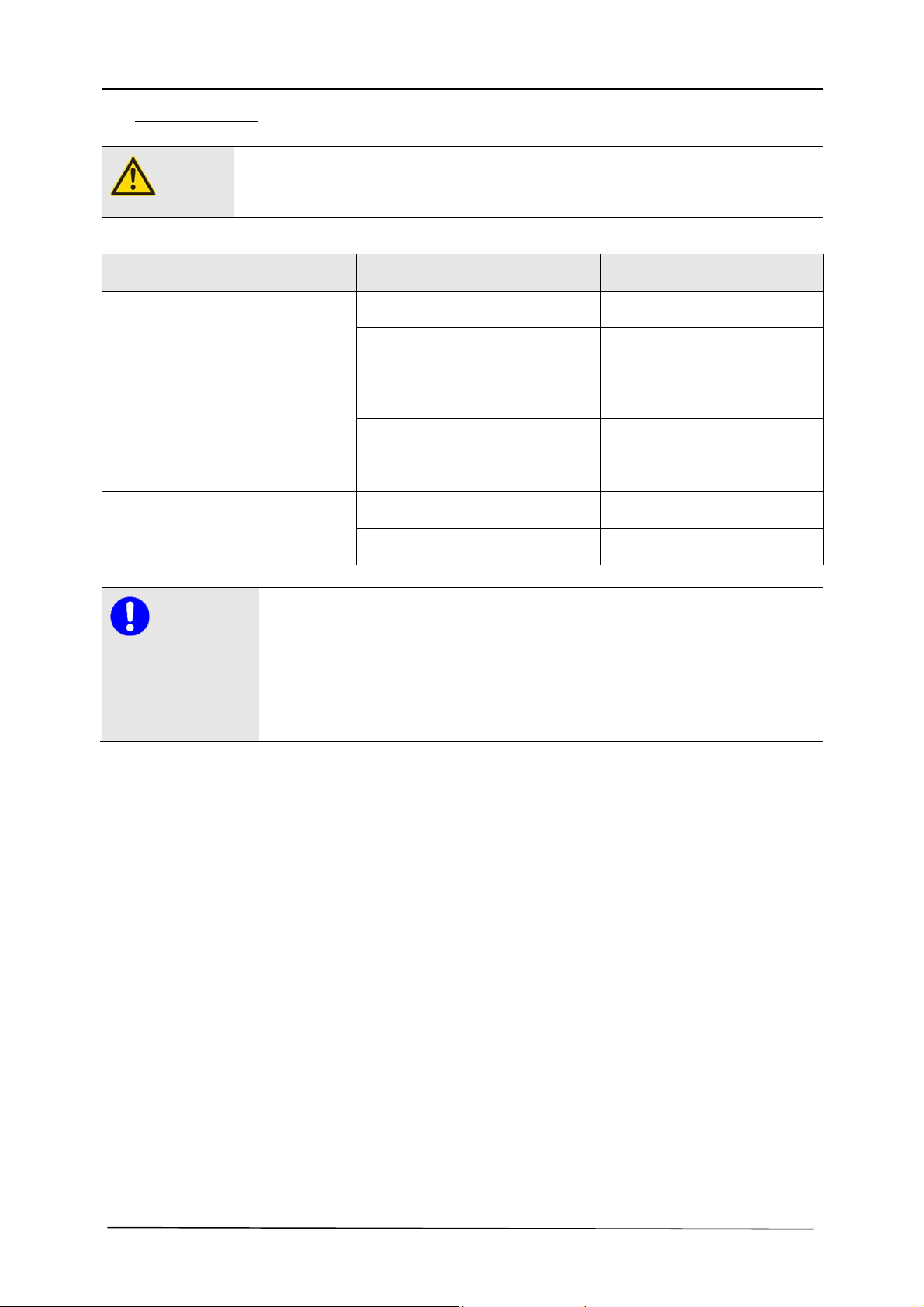
Error Cause Remedy
Low cutting performance Saw blade is dull Replace saw blade
Floor saw does not start Main switch in wrong position Main switch in position ON
Hand crank cannot rotate Spring lock not released Release the spring lock
Pull the power plug before any maintenance or repair work. Measures must be taken, so that an
accidental start-up by others is not possible. Maintenance and service works may only be carried out
by qualified personnel.
Too little cooling water Clean the water sieve or rinse the water
supply with pressure max. 5 bar
V-belt slips Retighten drive belts
Motor does not perform the full power see operating manual of the motor
Spring lock clamps Grease spring lock
Note
If the feed force is too large, the following points must be checked:
saw blade dull or defective?
too little water to cool the saw blade?
saw blade selection correct?
full power or rotation speed from the motor?
29/45
Page 30
6.3. Torque of screw connections
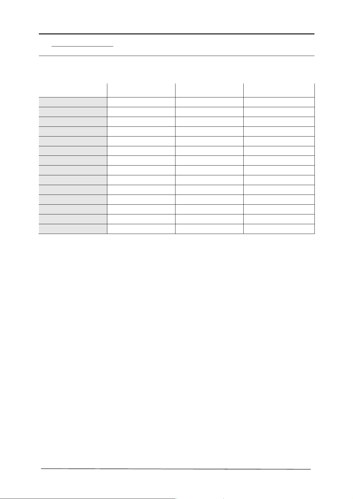
Strength class: 8.8 10.9 12.9
Dimensions Max. tightening torque in Nm Max. tightening torque in Nm Max. tightening torque in Nm
M4 3.3 4.8 5.6
M5 6.5 9.5 11.2
M6 11.3 16.5 19.3
M8 27.3 40.1 46.9
M10 54 79 93
M12 93 137 160
M14 148 218 255
M16 230 338 395
M18 329 469 549
M20 464 661 773
M22 634 904 1057
M24 798 1136 1329
M27 1176 1674 1959
M30 1597 2274 2662
30/45
Page 31
6.4. Maintenance plan
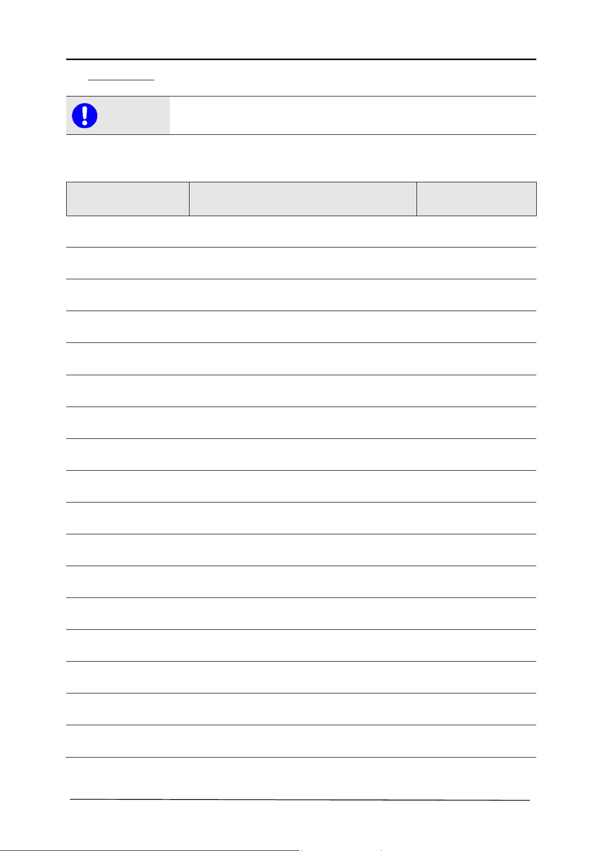
Note
Machine/type: Serial number/year of manufacture:
Date Performed maintenance or service works Date/signature
This section should be used as a proof of already performed maintenance and as a service book.
All warranty and service work must be entered as proof.
31/45
Page 32
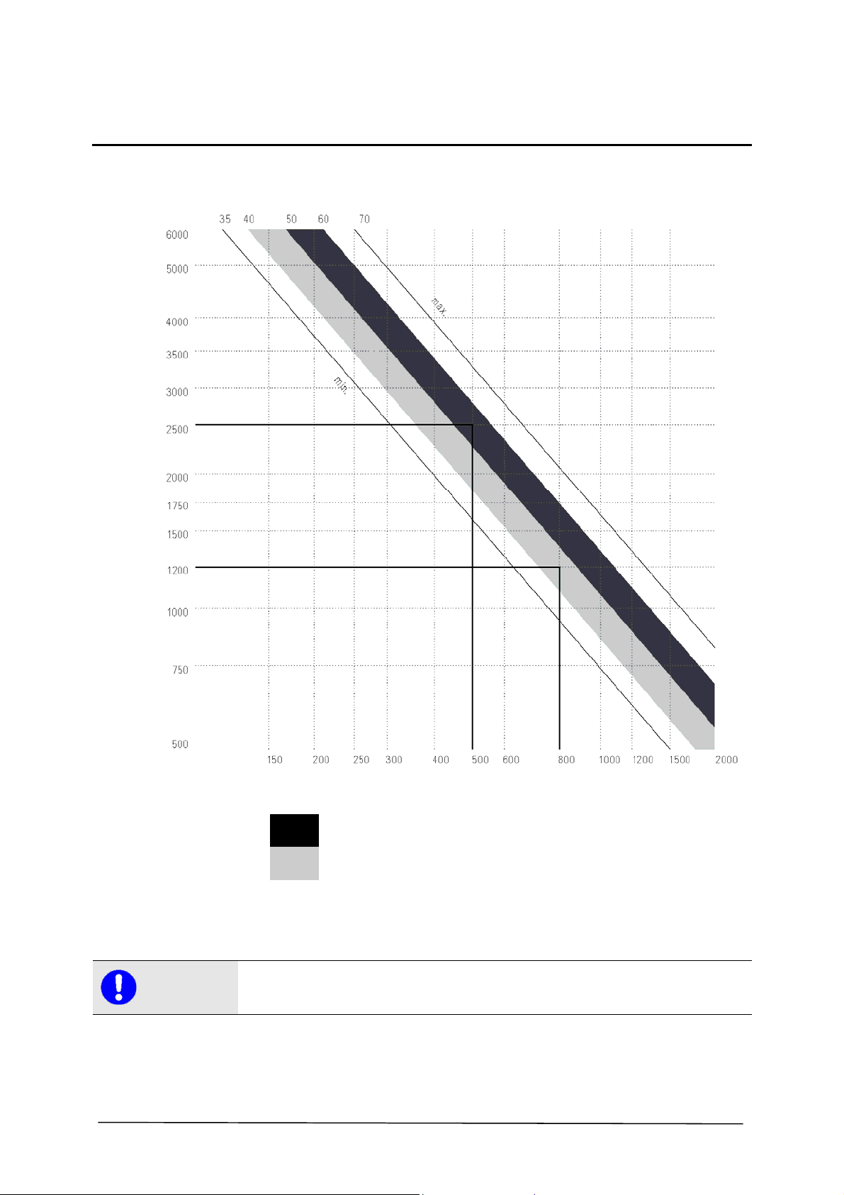
7. TOOLS
Peripheral speed m/s
Speed RPM
Diamond circular saw diameter mm
Note
Labelling for asphalt
Labelling for concrete
All tools in the area of diamond tools are marked in colours. Depending on the application
purpose and area, tools are different. To have the best results, the parameters must match. With
this diagram, the optimal cutting performance can be determined.
In the LISSMAC sales booklet, the prices for the tools are determined. This sales booklet can be
obtained from the manufacturer at any time.
32/45
Page 33
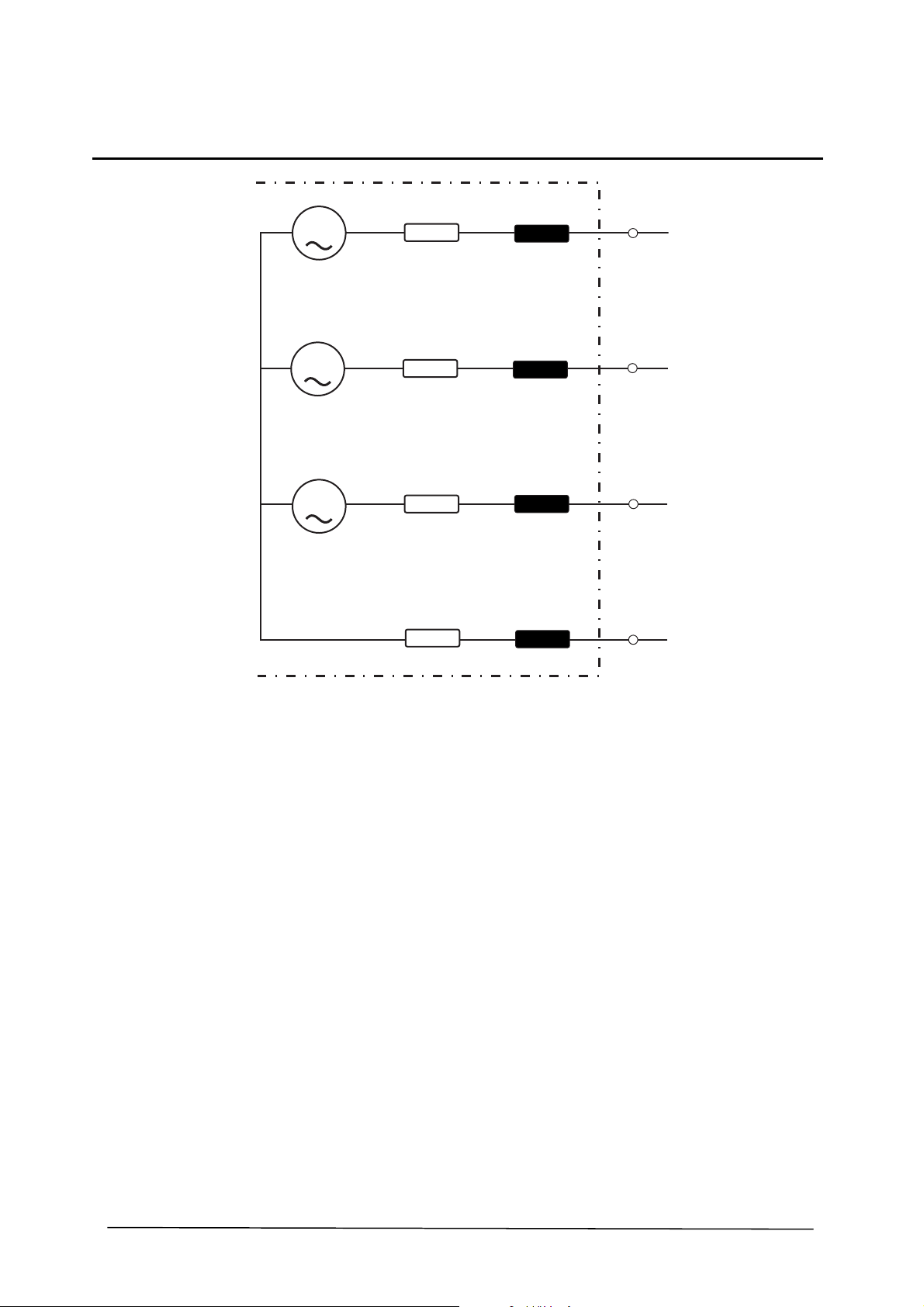
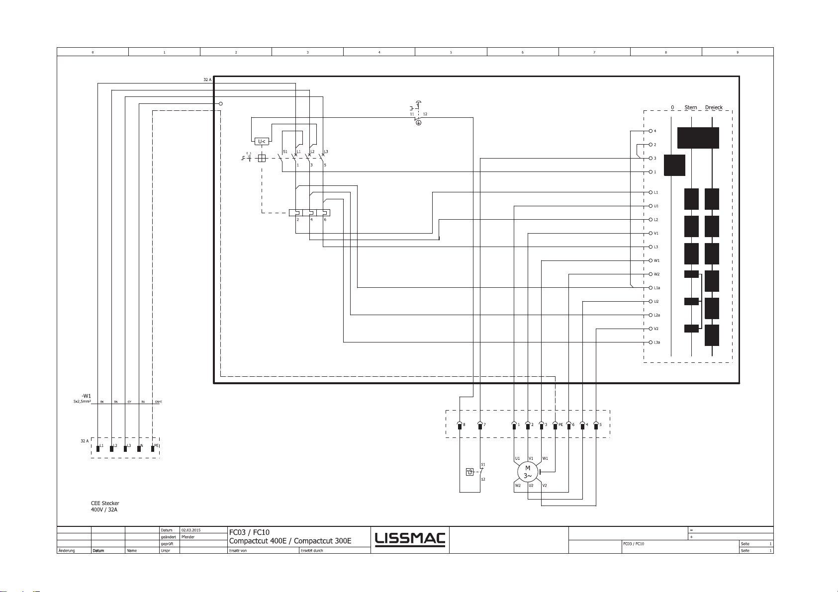
8. CONDITIONAL CONNECTIONS
G
G
G
R
R
R
R
A
A
A
N
X
A
i
X
A
i
X
A
i
X
N
j
L
1
L
2
L
3
N
Conditional connections according to EN 61000-3-3 or IEC 61000-3-11
RA=0.15Ω
jXA=0.1Ω on 50 Hz
RN=0.1Ω
jXN=0.06Ω on 50 Hz
33/45
Page 34

9. WARRANTY
The warranty for this machine is 12 months. For the following listed wear parts the warranty only
applies if the wear is not caused by operation.
Wear parts are parts that with intended use of the machine have limited operational wear. The wear
time is not uniformly specified, it differs according to intensity of use. Wear parts are device specific
and are to be maintained, adjusted and if required exchanged according to the manufacturers'
operating manual.
Wear caused by operation does not qualify for warranty claims.
Feed and drive elements, such as toothed racks, gears, pinions, spindles, spindle nuts, spindle
bearing, cables, chains, chain wheels, belts
Seals, cable, hoses, collars, connectors, couplings and switches for pneumatics, hydraulics,
water, electrical, fuel
Guide elements, such as guide strips, guide bushings, guide rails, rollers, bearings, anti-slide
plating
Tension elements from quick-coupling systems
Flushing head seals
Plain and roller bearings, which do not run in oil bath
Shaft sealing rings and sealing elements
Friction and overload couplings, braking equipment
Carbon brushes, collectors
Easily dissolvable rings
External potentiometer and manual switching elements
Fuses and lamps
Auxiliary and operating materials
Fastening elements, such as pegs, anchors and screws
Bowden cables
Lamella
Diaphragms
Spark plugs, glow plugs
Parts of reversing starters, such as crank cable, crank handle, crank roller, crank spring
Sealing brushes, sealing rubber, splash guard cloths
All types of filters
Drive and deflector rollers and bracings
Cable laying protection elements
Running and drive wheels
Water pumps
Cut goods transport rollers
Drilling, separating and cutting tools
Transport belt
Rubber scrapers
Needle felt protection
Energy storage
34/45
Page 35
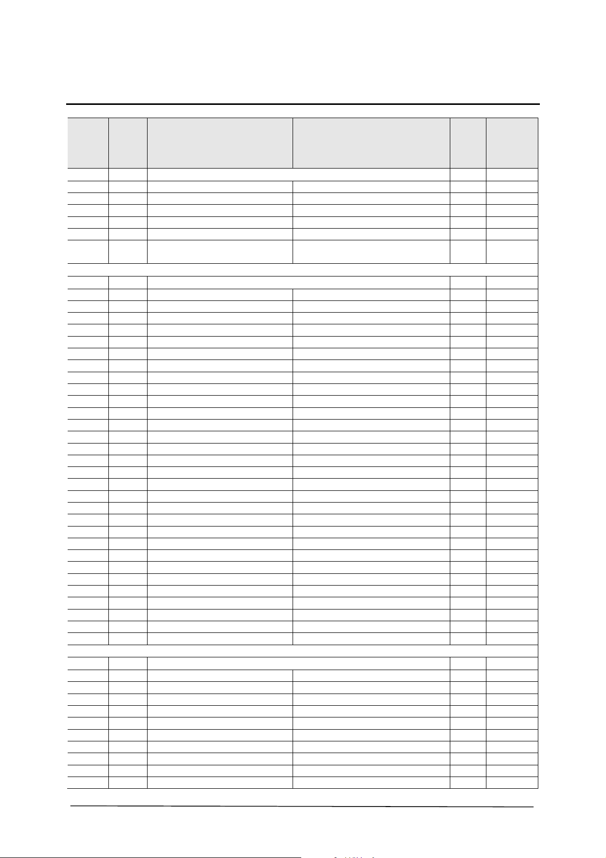
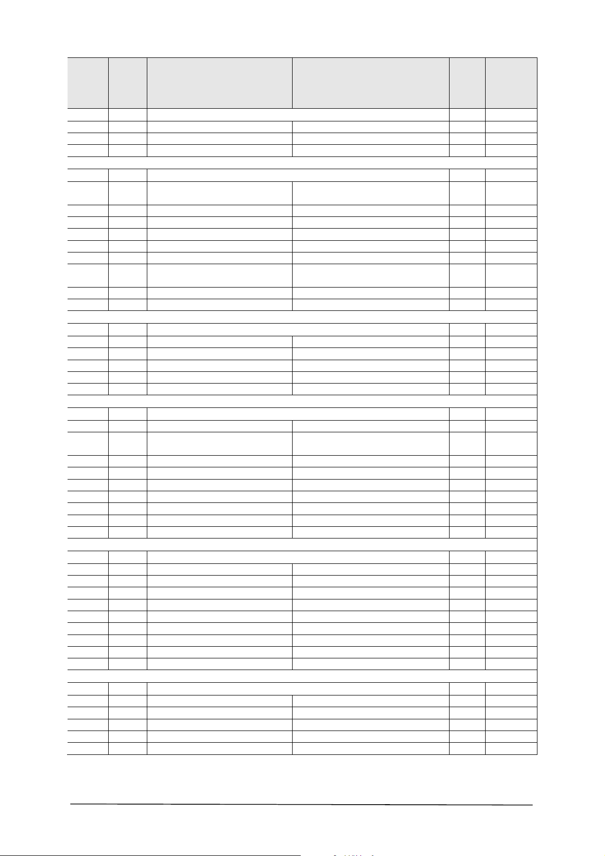
10. REPLACEMENT PARTS
Spare part
Item Item no. Designation Specification Units
1038 681399 HAND CRANK COUPL. 1 X
1038.1 300208 SPRING PIN ISO 8748 8 X 26 1
1038.2 300273 HEXAGON NUT DIN 934 8 1
1038.4 615467 ROTATING LEVER 1
1038.5 201183 SPACER SLEEVE 1
1038.6 209177 HANDLE 1
1038.7 360108 HEX SOCKET HEAD CAP SCREW WITH
ALLEN KEY DIN 912 8x60 GALV.
4000 681873 SPINDLE EXT. COUPL. 1 X
1026 201959 START UP DISC, PLASTIC 1
1027 261538 CYLINDER BUSH 2
1028 301664 COUNTERSUNK HEAD SCREW DIN 7991 12x45 1
1030 300398 HEXAGON HEAD SCREW DIN 933 12x40 GALV. 1
1031 300631 HEXAGON NUT DIN 439 12 GALV. 1
1032 300166 STEEL WASHER DIN 125 13 GALV. 3
1033 300559 LOCK NUT BIW V-SHAPE 12 MM 1
1038.1 300208 SPRING PIN ISO 8748 8 X 26 1
1038.2 300273 HEXAGON NUT DIN 934 8 1
1038.4 615467 ROTATING LEVER 1
1038.5 201183 SPACER SLEEVE 1
1038.6 209177 HANDLE 1
1038.7 360108 HEX SOCKET HEAD CAP SCREW DIN 912 8x60 GALV. 1
1040 202816 SPACER SLEEVE 1
1041 201959 START UP DISC, PLASTIC 1
1044 690489 SCALE PUSHER 1
1045 300808 WING SCREW DIN 316 6x16 GALV. 1
1046 628027 TRAPEZOIDAL SPINDLE 1
1047 691341 GUIDE PIPE 1
1048 206704 SCALE STICKER LABEL 0 -320 1
1049 205283 PLASTIC GLIDING STOPPER GL 35 1
1051 301166 HEXAGON HEAD SCREW DIN 931 12x70 GALV. 1
1052 300166 STEEL WASHER DIN 125 1
1053 261538 CYLINDER BUSH 1
1054 300576 STEEL WASHER 2
1055 201959 START UP DISC, PLASTIC 2
1056 261538 CYLINDER BUSH 1
1057 300559 LOCK NUT BIW V-FORM 2
1058 300166 STEEL WASHER DIN 125 A13 2
1059 206220 TENSION SPRING 1
4001 680373 STEERING ROD COUPL. 1 X
1090 300048 SAFETY SCREW 6 X 12 2
1091 300985 STEEL WASHER DIN 125 B 13.0 3
1092 615019 DISC FOR STEERING ROD 1
1093 613169 SOCKET FOR STEERING ROD 1
1094 280004 SOLID RUBBER WHEEL, PLASTIC RIMS 1 X
1095 300303 LOCKING RING DIN 471 D = 12 1
1096 615177 AXIS FOR STEERING ROD 1 X
1097 300003 RING SCREW DIN 580 8MM GALV. 2
1098 691408 STEERING ROD 1 X
1099 691407 STEERING ROD HOLDER 1
Recommen
dation
1
35/45
Page 36
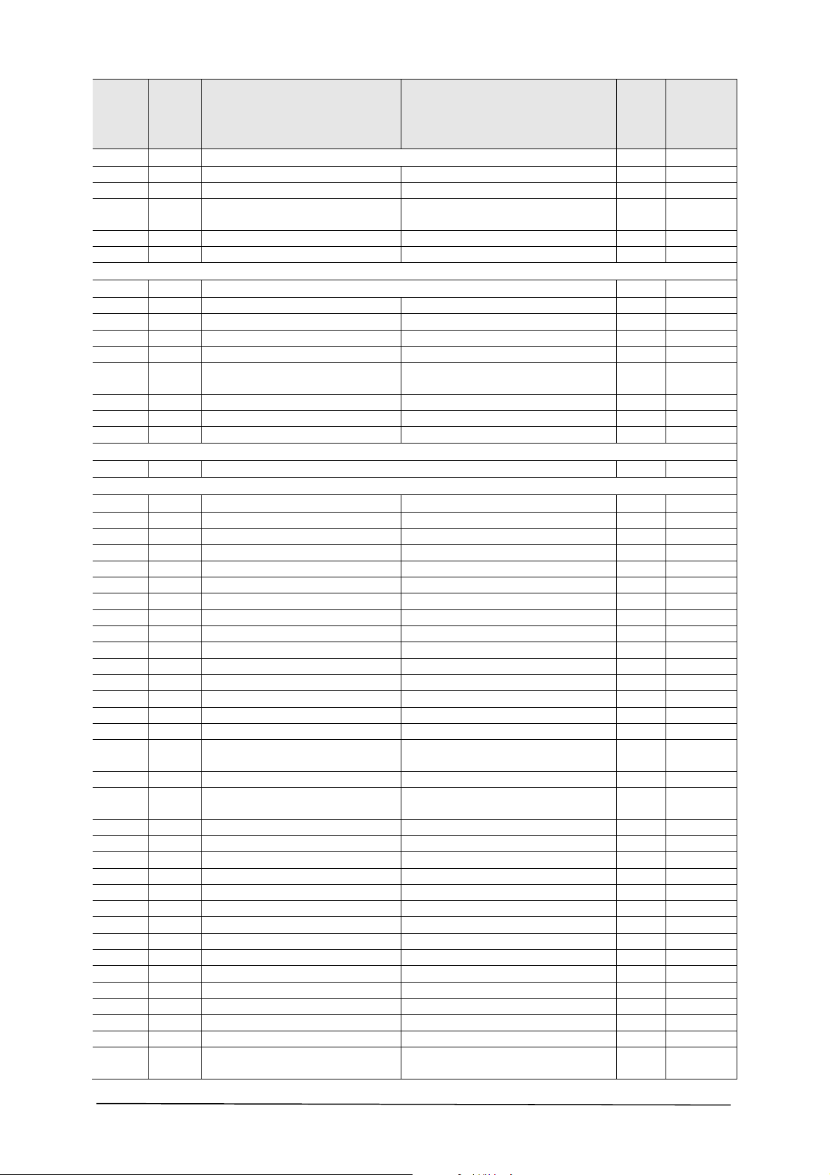
Spare part
Item Item no. Designation Specification Units
Recommen
dation
4002 681875 HANDLE ASSBLY. 2 X
1018 691344 HANDLE ASSBLY. 2
1019 280042 HANDLE PVC 4 X
1020 206233 SLIDE STOPPER 2
4003 681876 MOTOR FIXTURE ASSBLY. 1 X
2010 360131 HEX SOCKET HEAD CAP SCREW WITH
4
ALLEN KEY DIN 912 10x60 GALV.
2011 628032 MOTOR FIXTURE 2
2012 300778 SET SCREW DIN 914 8x8 V 2
2016 615357 CYLINDER PIN 4
2017 300423 SET SCREW DIN 914 20x80 V 2
2018 628033 CONNECTING PLATE 1
2019 300411 HEX SOCKET HEAD CAP SCREW WITH
2
ALLEN KEY DIN 912 8x30 GALV.
2020 300245 SCHNORR SAFETY WASHER 8.0 GALV.. 2
2021 628043 PIVOT SCREW 1
4004 681877 TENSIONING BOLT ASSBLY.
1 X
2041 628036 TENSIONING BOLTS 1
2042 260245 BALL BEARING 6004 2RS 3
2043 300332 ALIGNMENT DISC, STEEL DIN 988 20x28x1.0 2
2044 300333 ALIGNMENT DISC, STEEL DIN 988 20x28x0.5 2
2045 300120 LOCKING RING DIN 471 D = 20 1
4005 681824 WALL HOOD HOLDER 1 X
2111 613850 WALL HOOD HOLDER CC400 1
2112 301540 COUNTERSUNK HEAD SCREW W/
1
ALLEN KEY DIN 7991 12 X 25 12.9
2116 628028 SAW HOOD HOLDER FS27-E 1
2117 360147 HEXAGON HEAD SCREW DIN 933 8 X 70 MM GALVANIZED 1
2118 300125 STEEL WASHER DIN 125 A 8.4 GALV. 1
2121 300273 HEXAGON NUT DIN 934 8.0 MM, GALVANIZED 1
2122 601196 SEPARATOR 1
2123 300003 RING SCREW DIN 580 8.0 MM, GALVANIZED 1
2124 601197 BRAKING ROD 1
4006 681862 SAW HOOD 800 1 X
2097 613930 SIDE PANEL 2 1
2098 692651 SAW HOOD 800 SBG 1
2099 613924 FLANGE COVER PANEL 1
2100 200237 HANDLE DU. 6.5 MM X 122 MM 1
2101 300736 HEXAGON HEAD SCREW DIN 931 12 X 120 GALV. 1
2102 614584 SPRAY PANEL 1
2103 613926 RUBBER HOLDER 1
2104 212362 POLYURETHANE BLANK D44 1
2105 300080 HEXAGON NUT DIN 934 12.0 MM GALVANIZED 1
4007 681878 WATER TAP HOLDER ASSMBLY.
1 X
2079 280131 GEKA COUPLING HOSE PIECE 1 X
2080 280104 GEKA COUPLING THREADED PIECE 1 X
2081 280263 MINI BALL VALVE 1 X
2082 690482 WATER TAP HOLDER 1
2083 300604 WING SCREW DIN 316 8x16 GALV. 1
36/45
Page 37
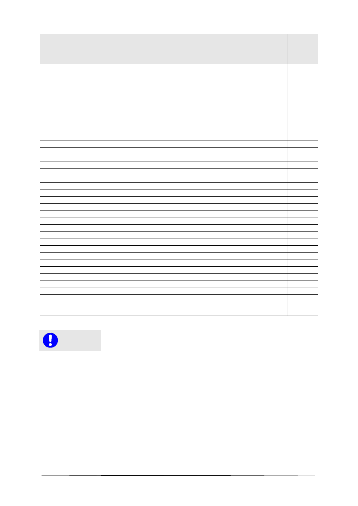
Item Item no. Designation Specification Units
Spare part
Recommen
dation
4008 680347 SPRAY PROTECTION ASSMBLY.
2136 628025 SPRAY PROTECTION PANEL 1
2137 628026 SPRAY PROTECTION PANEL 1
2138 300270 HEX SOCKET HEAD CAP SCREW WITH
ALLEN KEY DIN 912 5x16 GALV.
2139 206261 RUBBER SPRAY PROTECTION 1 X
2141 300258 BLIND RIVET ALU/STEEL ALU/STEEL 4 X 12 6
4009 681880 PLUG ASSMBLY. 1 X
3038 460606 CABLE SCREW FITTING 1
3040 400383 SKIN TIGHT REDUCTION 1
3041 402324 SOCKET HOUSING BG 10, 2xPG 21 1
3042 400541 SLEEVE INSERT 1
3044 300468 HEX SOCKET HEAD CAP SCREW WITH
ALLEN KEY DIN 912 5x12 GALV.
3045 300319 STEEL WASHER DIN 125 A 5.3 V 4
3049 400540 PIN INSERT 1
3050 400542 GROMMET HOUSING BG 10B, PG 16, 1
4010 403307 STAR TRIANGLE WITH MAIN SWITCH.
1001 691330 BASE FRAME
1002 300288 HEXAGON HEAD SCREW DIN 933 8x30 2
1003 360223 STEEL WASHER DIN 6340 8.4 GALV. 6
1004 300245 SCHNORR SAFETY WASHER 8.0 GALV.. 6
1005 300441 STEEL WASHER DIN 125 B 8.4 V 6
1006 212005 SOLID RUBBER WHEEL DU. 160 X 50 MM 4 X
1007 360223 STEEL WASHER DIN 6340 8.4 GALV. 2
1008 300635 ROUND HEADED SCREW ISO 7380 8x14 GALV. 2
1012 200693 SLIDE STOPPER 4
1013 628000 CARRYING PANEL 1
1014 300561 BLIND RIVET ALU/STEEL 3x8 4
1015 300604 WING SCREW DIN 316 8x16 GALV.. 2
1023 300559 LOCK NUT BIW V-FORM 1
1024 300274 STEEL WASHER DIN 6340, 13.0 MM GALV. 1
1025 261538 CYLINDER BUSH 1
1039 360033 HEX SOCKET HEAD CAP SCREW WITH
ALLEN KEY DIN 912 6x25 GALV.
1043 692420 SPINDLE FIXTURE 1
1061 360049 COUNTERSUNK HEAD SCREW WITH
ALLEN KEY DIN 7991 8x25
1062 628040 PANEL DISC 2
1063 300245 SCHNORR SAFETY WASHER 8.0 GALV.. 6
1064 628039 PANEL DISC 2
1065 628038 LONG SHAFT 1
1066 628030 PIVOT AXIS 1
1067 628041 BRAKE LEVER 1
1068 300202 SCHNORR SAFETY WASHER 10.0 GALV.. 1
1069 300342 HEXAGON HEAD SCREW DIN 933 10x25 GALV. 1
1070 628037 SHORT SHAFT 1
1072 300342 HEXAGON HEAD SCREW DIN 933 10x25 GALV. 1
1073 300202 SCHNORR SAFETY WASHER 10.0 GALV.. 1
1074 628011 BRAKING SHAFT 1
1077 691340 PIVOTING FRAME 1
1078 200693 SLIDE STOPPER 4
1084 300468 HEX SOCKET HEAD CAP SCREW WITH
ALLEN KEY DIN 912 5x12 GALV.
1 X
6
4
1 X
1
1
2
1
37/45
Page 38

Spare part
Item Item no. Designation Specification Units
1085 201386 TENSION CHECK STAY 1
1086 300319 STEEL WASHER DIN 125 A5.3 V 1
1087 300832 LOCK NUT BIW V-FORM 5 1
1100 206293 PLASTIC FLUSH SLEEVE 2 X
1101 300177 STEEL WASHER DIN 125 10.5 MM GALV. 2
1102 300240 LOCK NUT BIW V-FORM 2
1103 618338 THREADED ROD 1
1106 300132 SAFETY SCREW 6x16 VERBUS 1
1107 201406 PIPE CLAMP W/ RUBBER PROFILE 1
1108 200311 PIPE CLAMP W/ RUBBER PROFILE 1
1109 300833 LOCK NUT BIW V-FORM 6 1
1110 280152 OPEN ENDED SPANNER SW 36 1
1111 280204 OPEN ENDED SPANNER SW 19 1
1112 201655 OPEN ENDED SPANNER SW 10 1
2001 628607 MOTOR PANEL 1
2002 300297 COUNTERSUNK HEAD SCREW DIN 7991 10x50 GALV. 1
2003 628608 SPACER - MOTOR PANEL 1
2005 404518 ELECTRIC MOTOR 1
2008 300559 LOCK NUT BIW V-FORM 4
2009 300166 STEEL WASHER DIN 125 A13 MM GALV. 4
2022 300555 HEXAGON NUT DIN 439 20x1.5 1
2023 201488 FOLDING SPLINT 1
2024 618275 PROTECTION PANEL 1
2025 300561 BLIND RIVET ALU//STEEL ALU/STEEL 3x8 4
2026 300015 RING NUT DIN 582 20.0 GALV.. 2
2029 628035 INTERMEDIATE FLANGE 1
2030 628034 SWORD 1
2031 300239 HEXAGON HEAD SCREW DIN 933 10x50 GALV. 2
2032 300297 COUNTERSUNK HEAD SCREW WITH
ALLEN KEY DIN 7991 10x50 GALV.
2034 360138 HEXAGON HEAD SCREW DIN 933 6x40 GALV. 2
2035 300617 HEXAGON NUT DIN 439 6.0 V 2
2038 300796 HEXAGON HEAD SCREW DIN 933 12x30 GALV. 2
2039 300574 SCHNORR SAFETY WASHER 12.0 GALV.. 2
2040 300274 STEEL WASHER 2
2048 300915 SET SCREW DIN 914 6x12 V 1
2049 615358 V-BELT PULLEY 1 X
2050 206253 V-BELT XPA 832 1 (3x) X
2053 615190 HEXAGON HEAD SCREW 1
2054 615188 SEPARATOR 1 X
2055 280253 BALL BEARING 6208 2RS 3 X
2056 615158 V-BELT DISC SAW BLADE 1 X
2057 615164 BEARING PINS 1 X
20581.
2058.2
2059 615187 SEPARATOR 1 X
2060 691343 BELT GUARD ASSMBLY. 1
2061 200241 SEALING RING V-SEAL NBR 60° 1 X
2062 628031 SAW BLADE FLANGE 1
2063 300267 SET SCREW 1 X
2064 300279 SCHNORR SAFETY WASHER 6.0 MM 6
2065 300473 HEX SOCKET HEAD CAP SCREW WITH
2066 601020 PRESSURE DOSC 1
2067 301268 CROWN NUT DIN 937 24 X 1.5 1 X
2068 280235 LOCKING RING 1 X
2069 200237 PLASTIC HANDLE 1 X
2070 300276 HEXAGON HEAD SCREW DIN 933 6x16 GALV. 2
200240 GLIDING RING SEALING SET 91118+96064 1 X
ALLEN KEY DIN 912 6x35 GALV.
Recommen
dation
2
6
38/45
Page 39
Spare part
Item Item no. Designation Specification Units
2072 300048 SAFETY SCREW 6 X 12 2
2074 300248 DISC DIN 125 A 6.4 V 2
2075 300833 HEXAGON NUT BIW V-FORM 6 2
2076 613115 HOSE NIPPLE 1
2077 300135 SINGLE-EAR CLAMP 16,5 R 2
2078 200322 PVC HOSE 1
3001 400060 PHASE TURNING PLUG CEE PLUG 400 V 1
3004 400338 FLEXIBLE LINE 1
3005 200495 PIPE CLAMP WITH RUBBER PROFILE 2
3006 300270 HEX SOCKET HEAD CAP SCREW WITH
ALLEN KEY DIN 912 5x16 GALV.
3007 300832 LOCK NUT BIW V-FORM 5 1
3008 403166 CABLE SCREW FITTING 2
3010 403168 LOCK NUT 2
3013 403307 STAR TRIANGLE SWITCH 1
3016 300270 HEX SOCKET HEAD CAP SCREW WITH
ALLEN KEY DIN 912 5x16 GALV.
3017 300317 HEXAGON NUT DIN 934 5.0 V 4
3018 300248 STEEL WASHER DIN 125 A 6.4 V 4
3019 300279 SCHNORR SAFETY WASHER 6.0 MM 4
3020 300627 CAP NUT DIN 917 5.0 GALV.. 4
3022 400610 EMERGENCY STOP ASSMBLY. 1 X
3023.1 403441 MAIN SWITCH INSERT 1 X
3023.2 400481 SWITCH COVER PLATE 1 X
3023.3 400482 ROTATING HANDLE SWITCH 1 X
3024.1 403440 STAR TRIANGLE SWITCH INSERT 1 X
3024.2 402230 COVER PLATE 1
3024.3 280221 ROTATING HANDLE 1 X
3037 403255 FLEXIBLE LINE 1
3046 300832 LOCK NUT BIW V-FORM 5 4
3048 400521 PROTECTIVE HOSE CABLE 1
3053 403255 CABLE 1
--- 216095 SIEVE FOR WATER SUPPLY 1 X
--- 205238 HAND CRANK FOR SETTING DEPTH 1 X
--- 206609 FAN VANE FOR E-MOTOR 1 X
--- 206590 FAN HOOD FOR E-MOTOR 1 X
Recommen
dation
1
4
Note
To prevent incorrect deliveries, when ordering spare parts, indicate the complete model
designation, year of manufacture and the machine number!
Technical changes may be made!
We make it explicitly clear that parts not supplied by us are also not tested and released by us.
The installation and use of such products can therefore, in certain conditions, modify your
equipment negatively and thus affect safety. For damages caused by the use of non-original parts
and accessories, there is no liability!
39/45
Page 40
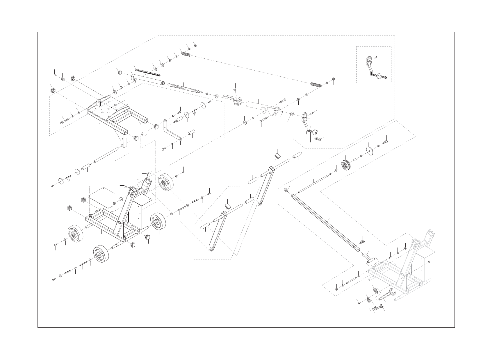
1078
4002
4001
4000
1038
1084
1061
1051
1085
1052
1062
1078
1053
1063
1012
1064
1014
1065
1012
1077
1066
1013
1054
1049
1055
1015
1023
1056
1024
1048
1047
1086
1087
1078
1025
1015
1055
1054
1078
1057
1072
1006
1058
1068
1003
1059
1073
1007
1058
1069
1070
1067
1005
1046
1008
1057
1064
1003
1063
1074
1004
1062
1003
1032
1061
1002
1041
1044
1020
1045
1018
1026
1027
1019
1019
1043
1030
1027
1020
1028
1040
1018
1097
1031
1038.4
1019
1032
1038.1
1038.2
1038.5
1096
1038.6
1032
1038.7
1095
1033
1091
1098
1094
1093
1091
1092
4000
1038
1091
1090
4001
40/45
1008
1002
1003
1007
1004
1006
1003
1005
1003
1001
1006
1012
1012
1006
1019
4002
1102
110 1
110 3
1106
110 0
1097
110 7
1108
1099
10
1112
110 2
1101
1100
1109
36
1110
19
1111
COMPACTCUT 400
Stand: 03-08-2015
Blatt 1/3
Page 41
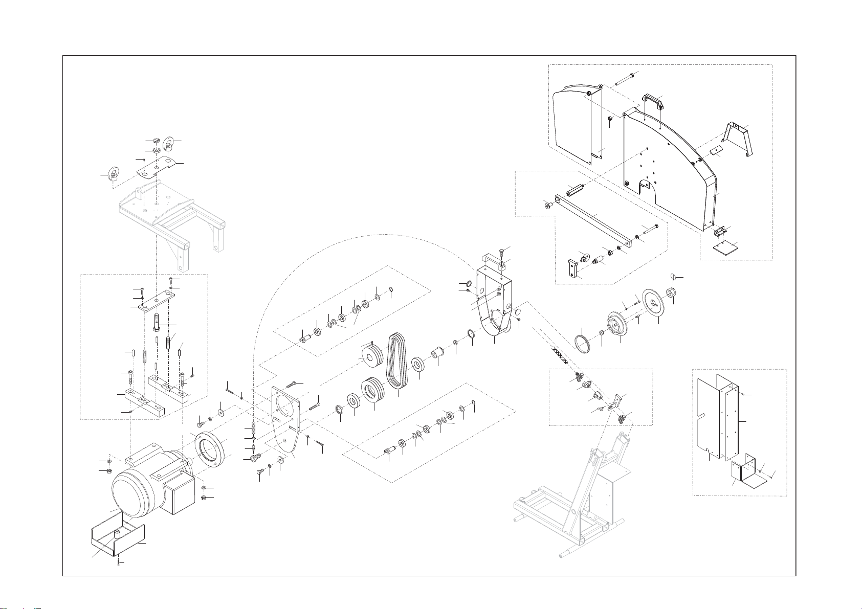
4004
4004
4003
4007
4008
4006
4005
2026
4003
2009
2008
2005
2010
2011
2012
2018
2016
2025
2019
2020
2023
2022
2019
2020
2021
2017
2029
2026
2024
2016
2012
2010
2011
2038
2039
2040
2009
2008
2034
2078
2077
2076
2053
2035
2038
2039
2040
2041
2035
2030
2042
2031
2032
2034
2043
2042
2054
2043
2044
2048
2049
2055
2042
2044
2056
2045
2041
2050
2042
4004
2055
2042
2043
2057
2042
2043
2044
2071
2072
2058.2
2074
2075
2059
2045
2044
2060
4004
2070
2069
2072
4005
2112
2111
2079
2123
2080
2061
2081
2083
2125
2124
2105
2116
2058.1
2097
2122
2064
2062
2117
2121
2065
2063
4007
2082
2080
2101
2118
2066
2100
2067
2068
2136
2102
2098
2139
2103
2104
4006
2099
2138
2137
2140
4008
2141
2003
2002
2001
COMPACTCUT 400
Stand: 24-10-2016
Blatt 2/3
41/45
Page 42
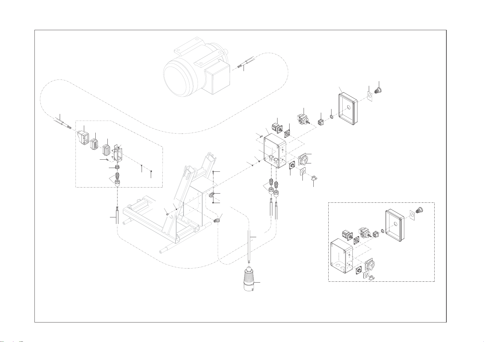
3053
4009
4010
3013
3022.1
3022.2
3048
3050
4009
3049
3044
3040
3038
3037
3042
3041
3045
3046
3020
3019
3006
3005
3007
3005
3018
3016
3017
3010
3013
3008
3004
3024.1
3024.2
3024.2
3023.1
0
3024.2
Y
3024.3
3022.4
3023.2
3023.3
3022.3
4010
0
Y
42/45
3001
COMPACTCUT 400
Stand: 23-09-2014
Blatt 3/3
Page 43
43 / 45
Page 44
Translation of the original declaration of conformity
This EC Declaration of Conformity is valid for the following machine:
LISSMAC Floor saw COMPACTCUT 400 E.
This declaration relates exclusively to the machine in the state in which it was placed on the
market, and excludes components which are added and/or operations carried out subsequently
Manufacturer:
Machine description:
LISSMAC Maschinenbau GmbH
The LISSMAC floor saw is a floor cutting grinder and is designed exclusively for cutting grooves
by the final user. It is confirmed that the machine conforms to the relevant provisions of
Directive 2006/42/EC and 2000/14/EC.
Lanzstrasse 4
D-88410 Bad Wurzach
Technical documentation retained by LISSMAC Maschinenbau GmbH, D-88410 Bad Wurzach
into concrete or asphalt using water. Cutting uses saw blades and the machine may only be
operated for cutting of floors.
COMPACTCUT 400 E
Cut depth, max. 320 mm
Max. saw blade Ø 800 mm
Saw blade holder 25.4 mm
Drive motor Electric motor
Output power max. 7.5 kW
Power consumption 400 V / 16.1 A
Saw blade speed 1250 1/min
Guaranteed noise power level 95 dB
Measured noise level LwA 96 dB
Weight 167 kg
Harmonised standards:
Legally binding
representative:
s
EN 13862:2010-03
EN ISO 12100 Corrigendum 1:2013-08
EN 60204-1:2014-10; VDE 0113-1:2014-10
EN 55014-1:2012-05; VDE 0875-14-1:2012-05
EN 55014-2:2016-01; VDE 0875-14-2:2016-01
EN 61000-3-11:2001-04; VDE 0838-11:2001-04
EN 61000-3-12:2012-06; VDE 0838-12:2012-06
Electromagnetic Compatibility IEC 61000-3-11
Conditional connections: RA=0.15Ω, jXA=0.1Ω at 50 Hz, RN=0.1Ω, jXN=0.06Ω at 50 Hz
LISSMAC Maschinenbau GmbH
Lanzstrasse 4
88410 Bad Wurzach
Tel.: +49 (0) 7564 / 307 - 0
Fax: +49 (0) 7564 / 307 - 500
E-mail: [email protected]
www.lissmac.com
Bad Wurzach den 01.02.2016
...........................................
ppa. Benjamin Mayer
(Head of Development Construction Technology)
Page 45

s
45 / 45
 Loading...