

Page 1
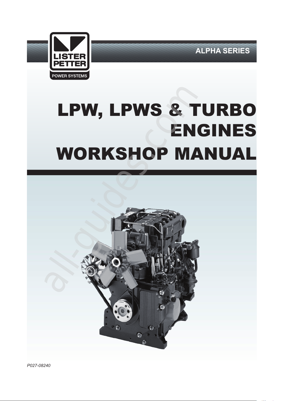
LPW, LPWS & TURBO
ENGINES
WORKSHOP MANUAL
ALPHA SERIES
P027-08240
All manuals and user guides at all-guides.com
all-guides.com
Page 2
2
Associated Publications
Master Parts Manual .............................................................................................................. P027-08046
Technical Handbook .................................................................................................................. P027-08247
Operators Handbook .............................................................................................................. P027-08201
Note:
Some information is not yet available and will be included in a later edition.
Associated Publications
Operators Handbooks
LPW, LPWS, LPWT
- English ............................................................................................................................. P027-08182
- German ..................................................................................................................... P027-08182/ger
- Italian ...........................................................................................................................P027-08182/ita
- French ........................................................................................................................ P027-08182/fre
- Spanish .....................................................................................................................P027-08182/spa
- Portuguese ...................................................................................................................... P027-08196
LPW, LPWS, LPWT
- English ............................................................................................................................. P027-08270
- French ........................................................................................................................ P027-08270/fre
- Spanish .....................................................................................................................P027-08270/spa
Master Parts Manuals
LPW/LPWS ............................................................................................................................ P027-08041
LPWS 400 Series .................................................................................................................... P027-08111
Disclaimer
Th e i nformation, s pecifications, illustrations,
instructions and statements contained within this
Our policy is one of continued development and
we reserv e t he right t o a mend any technical
information with or without prior notice. Whilst
every effort is made to ensure the accuracy of the
particulars contained within this publication neither
the Manufacturer, the Distributor nor the Dealer
shall in any circumstances be held liable for an
y
inaccuracy or the consequences thereof.
The information given is subject to the Company’s
current Conditions of Tender and Sale, is for the
assistance of users and is based upon results
obtained from tests carried out at the place of
manufacture. The Company does not guarantee that
the same results will be obtained elsewhere under
different conditions.
© Copyright Lister Petter Limited Power Systems
All rights reserved
publication are given with Lister Petter Power
Systems' best intentions and are believed to be
correct at the time of going to press.
All manuals and user guides at all-guides.com
Page 3
3
CONTENTS
Introduction ...........................................................................................................................4
1. General Information ..........................................................................................................5
2. Engine Servicing and Adjustments .................................................................................12
3. Engine Fluids ..................................................................................................................59
4. Operating Instructions .................................................................................................... 62
5. Routine Maintenance...................................................................................................... 65
6. Troubleshooting .............................................................................................................. 74
7. Engine Build Details ....................................................................................................... 77
8. Technical Data ................................................................................................................80
9. Dismantle and Rebuild ................................................................................................... 82
10. Conversion Factors ...................................................................................................... 84
All manuals and user guides at all-guides.com
Page 4
ALPHA SERIES ENGINES WORKSHOP MANUAL
4
WARNING
Unauthorised adjustments to the emission
compliant fuel injection pump may invalidate
warranty claims. In the USA, unauthorised
adjustment of emission critical components
is prohibited by Federal Law, incurring civil
penalty.
INTRODUCTION
The purpose of this manual is to give information,
operating, maintenance and repair procedures for
the 'Alpha' series of industrial, marine and gas
fuelled engines.
The manual is designed primarily for use by
qualified technicians with electrical and
mechanical experience.
This work can only be carried out if the necessary
hand and service tools are available. When the
user has insufficient tools, experience or ability to
carry out adjustments, maintenance and repairs
then this work should not be attempted.
Where accurate measurements, or torque values,
are required they can only be made using
calibrated instruments.
Under no circumstances should makeshift tools or
equipment be used, as their use may adversely
affect safe working procedures and engine
operation.
The specification details given apply to a range of
engines and not to any one particular engine. In
cases of difficulty the user should consult the local
Lister Petter Power Systems Distributor or Dealer
for further advice and technical assistance.
The information, specifications, illustrations,
instructions and statements contained within this
publication are given with our best intentions and
are believed to be correct at the time of going to
press. Our policy is one of continued development
and we reserve the right to amend any technical
information with or without prior notice.
Whilst every effort is made to ensure the accuracy
of the particulars contained within this publication,
neither the Manufacturer, Distributor or Dealer
shall in any circumstances be held liable for any
inaccuracy or the consequences thereof.
The information given is subject to the Company’s
current Conditions of Tender and Sale, is for the
assistance of users and is based upon results
obtained from tests carried out at the place of
manufacture. This Company does not guarantee
that the same results will be obtained elsewhere
under different conditions.
Parts that have not been approved by the Lister
Petter Power Systems organisation cannot be
relied upon for correct material, dimensions or
finish. This Company cannot therefore, be
responsible for any damage arising from the use of
such parts and the guarantee will be invalidated.
When purchasing parts or giving instructions for
repairs users should, in their own interests, always
specify Genuine Lister Petter Parts and quote the
Description of the Part and the Engine Serial
Number.
Various technical/sales leaflets are available;
please contact your Lister Petter Power Systems
Distributor or Dealer for details.
Training
Comprehensive training in the correct operation,
service and overhaul procedures of engines is
available at the Lister Petter Power Systems
International Product Training Centre.
Please contact Lister Petter Power Systems for
details.
If Problems Occur
If problems occur with your engine, or any of the
Lister Petter approved accessories fitted to it, your
local Lister Petter Power Systems Distributor
should be consulted.
There are Lister Petter Power Systems
Distributors in most countries of the world and
details for these can be obtained from any one of
the companies listed on the back cover or
www.listerpetter.com
Using this Workshop Manual
Each section title is given at the top of the relevant
pages and a full cross reference 'Index' appears at
the back of the manual.
It is recommended the individual steps contained
in the various maintenance or repair operations
are followed in the sequence in which they appear.
At times it may be necessary to refer to other parts
of the section, or to a different section, for more
specific or detailed information.
All manuals and user guides at all-guides.com
Page 5
ALPHA SERIES ENGINES WORKSHOP MANUAL
5
1.1 SAFETY PRECAUTIONS AND
SAFE WORKING PRACTICES
At all times follow the recommended precautions
and safe operating and working practices.
The following are of a general nature and more
specific information appears where it is relevant.
Caution and Warning Symbols
When an engine is operating or being overhauled
there are a number of associated practices which
may lead to personal injury or product damage. The
following are applied throughout this publication.
CAUTION
This caution symbol draws attention to special
instructions or procedures which, if not correctly
followed, may result in damage to, or destruction
of, equipment.
WARNING
This warning symbol draws attention to special
instructions or procedures which, if not strictly
observed, may result in personal injury.
WARNING
A WARNING SYMBOL WITH THIS TYPE OF
TEXT DRAWS ATTENTION TO SPECIA L
INSTRUCTIONS OR PROCEDURES WHICH, IF
NOT STRICTLY OBSERVED, MAY RESULT IN
SEVERE PERSONAL INJURY, OR LOSS OF LIFE.
Follow all Safety Instructions
a. Carefully read all safety messages in this manual
and the safety and informative symbols on your
engine and plant.
b. Starting any diesel engine can be dangerous
in the hands of inexperienced people. Engine
operators must be instructed in the correct
procedures before attempting to start any engine.
c. Do not make any unauthorised modifications as
these may affect the safe operation of the engine
and put the operator at risk.
d. Ensure all starting devices are removed, or
isolated, before commencing any work on the
engine or plant.
Emergency Considerations
a. Be prepared with suitable equipment, and
knowledge, in case a fire starts.
b. Know where to make calls to the emergency
services from.
Handling Fluids Safely
a. When working with fuel or batteries do not smoke
or work near to heaters or other fire hazards.
b. Store flammable liquids away from fire hazards.
c. Do not expose pressurised containers to heat
and do not incinerate or puncture them.
d. Handle fuel with care and always stop the engine
before refuelling. Do not overfill the fuel tank.
e. Thoroughly clean any lubricating or fuel oil from
the skin as soon as possible.
f. Rectify all fuel, coolant and oil leaks as soon
as practicable and clean any spills when they
occur.
g. Remove any build-up of grease, oil or debris.
h. Batteries contain sulphuric acid - if the acid has
been splashed on the skin, eyes or clothes flush
it away with copious amounts of fresh water and
seek medical aid.
Protective Clothing and Equipment
a. Tie long hair close to your head.
b. Do not wear a necktie, scarf, loose clothing
or necklace when working close to a running
engine.
Rotating Machinery
a. Entanglement with any rotating equipment can
cause serious injury or death.
b. If unprotected skin comes into contact with
rotating equipment severe burns can result.
c. It is advisable to remove rings and other jewellery
to prevent possible entanglement in moving
parts. These items could also cause an electric
short circuit if any part of the electrical system is
being worked on.
d. Ensure any lifting equipment to be used has the
correct capacity to lift the engine.
e. Lifting equipment must be designed to give two
vertical lifts from directly above the engine lifting eyes.
f.
g. Do not work under any plant that is only held by
overhead lifting equipment.
Personal Safety
a. Wear close fitting clothing and personal protective
clothing and safety equipment appropriate to the
work being done.
1. GENERAL INFORMATION
The engine lifting eyes fitted to the engine are
suitable for lifting the engine and accessory
assemblies originally fitted by Lister Petter Power
Systems. They must not be used to lift the
complete plant.
c. Ensure a third party knows where you are working
and when you leave the working area.
All manuals and user guides at all-guides.com
Page 6
ALPHA SERIES ENGINES WORKSHOP MANUAL
6
b. Wear suitable ear protection to protect against
objectionable or uncomfortable loud noise.
Prolonged exposure to loud noise can cause
impairment, or loss of hearing.
c. The use of music or radio headphones could
cause a loss of concentration.
Handling Chemical Products Safely
a. Direct exposure to hazardous chemicals can
cause serious injury.
b. Potentially hazardous chemicals include such
items as lubricants, fuel, coolant concentrate,
battery acid, paint and adhesives.
c. Manufacturers Safety Data Sheets will provide
specic details of the physical and health
hazards, safety and emergency procedures and
any necessary personal protection equipment
required while working with hazardous
materials.
Safe Maintenance Considerations
a. Understand the service procedures before
commencing any work.
b. Ensure the work area is clean, dry, well ventilated
and has adequate lighting.
c. Isolate the engine starting system before
commencing any work on the plant.
d. All persons using equipment or processes in
connection with the maintenance of plant and
machinery must have received adequate and
suitable training.
High Pressure Fluids
a. Never allow any part of the body to come
into contact with high pressure hydraulic oil,
compressed air or fuel oil, for example when
testing fuel injection equipment.
b. Both digested and injested uids can lead to
serious injury, possibly with fatal results in a very
short period of time.
Electrical System Considerations
a. Ensure that the battery is of sufcient capacity to
start the engine down to its minimum operating
temperature taking into account any drag that
may be imposed on the engine by the type of
transmission that is attached to it.
b. Ensure the battery and all engine wiring cables
are of sufcient size to carry the currents
required.
c. Check that the engine mounted alternator is of
sufcient output to cope with the total electrical
load required by the machine to which it is tted.
d. Ensure engine wiring cables are:-
Bound together in a loom and adequately
supported.
Routed to avoid any hot surfaces, particularly the
exhaust system.
Not in contact with any sharp corners or rough
surfaces so as to avoid any possibility of chafng
taking place.
Alternator Precautions
a. Never remove any electrical cable without rst
disconnecting the battery.
b. Only disconnect the battery with the engine
stopped and all switches in the OFF position.
c. Ensure cables are tted to their correct terminals.
A short circuit or reversal of polarity will ruin
diodes and transistors. Never connect a battery
into the system without checking that the voltage
and polarity are correct.
d. Never ash any connection to check the current
ow or experiment with any adjustments or
repairs to the system.
e. The battery and alternator must be disconnected
before commencing any electric welding when a
pole strap is directly or indirectly connected to the
engine.
Starter Battery Precautions
WARNING
Sulphuric acid in battery electrolyte is poisonous,
is strong enough to burn skin, eat holes in
clothing and cause blindness if splashed into
the eyes.
a. Do not smoke near the batteries and keep sparks
and ames away from them.
b. Batteries contain sulphuric acid - if the acid has
been splashed on the skin, eyes or clothes ush
it away with copious amounts of fresh water and
seek immediate medical aid.
c. Keep the top of the battery well ventilated during
charging. Switch off the battery charger before
connecting or disconnecting the charger leads.
d. Disconnect the battery negative (earth) lead rst
and reconnect last.
e. Never 'ash' connections to check current ow.
f. A damaged or unserviceable battery must never
be used.
g. Do not attempt to charge a frozen battery; it may
explode; warm the battery to 16°C (60°F).
Waste Contamination
a. Extreme care must be taken to ensure that waste
oil, fuel, lter elements, coolant concentrate,
battery electrolyte, solvents or other toxic
All manuals and user guides at all-guides.com
all-guides.com
Page 7
ALPHA SERIES ENGINES WORKSHOP MANUAL
7
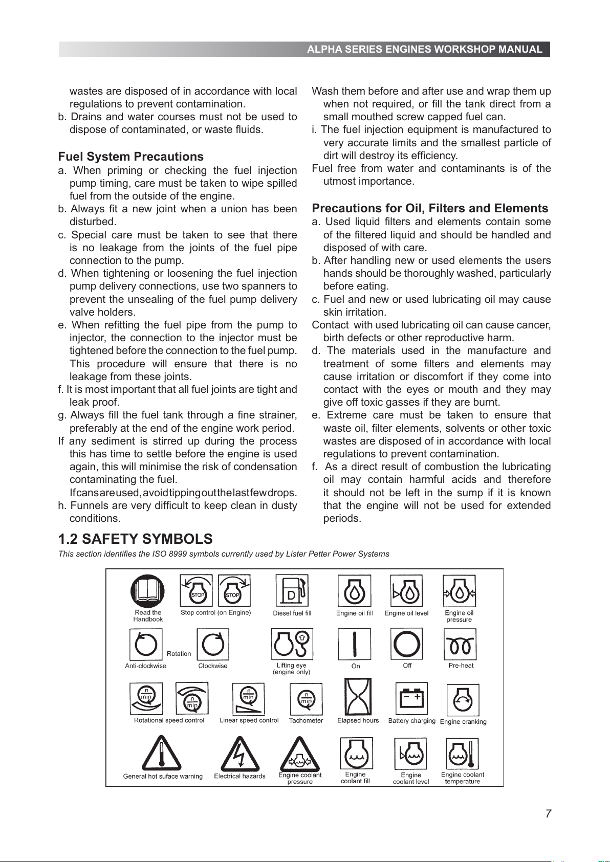
1.2 SAFETY SYMBOLS
This section identifies the ISO 8999 symbols currently used by Lister Petter Power Systems
wastes are disposed of in accordance with local
regulations to prevent contamination.
b. Drains and water courses must not be used to
dispose of contaminated, or waste fluids.
Fuel System Precautions
a. When priming or checking the fuel injection
pump timing, care must be taken to wipe spilled
fuel from the outside of the engine.
b. Always fit a new joint when a union has been
disturbed.
c. Special care must be taken to see that there
is no leakage from the joints of the fuel pipe
connection to the pump.
d. When tightening or loosening the fuel injection
pump delivery connections, use two spanners to
prevent the unsealing of the fuel pump delivery
valve holders.
e. When refitting the fuel pipe from the pump to
injector, the connection to the injector must be
tightened before the connection to the fuel pump.
This procedure will ensure that there is no
leakage from these joints.
f. It is most important that all fuel joints are tight and
leak proof.
g. Always fill the fuel tank through a fine strainer,
preferably at the end of the engine work period.
If any sediment is stirred up during the process
this has time to settle before the engine is used
again, this will minimise the risk of condensation
contaminating the fuel.
If cans are used, avoid tipping out the last few drops.
h. Funnels are very difficult to keep clean in dusty
conditions.
Wash them before and after use and
wrap them up
when not required, or fill the tank direct from a
small mouthed screw capped fuel can.
i. The fuel injection equipment is manufactured to
very accurate limits and the smallest particle of
dirt will destroy its efficiency.
Fuel free from water and contaminants is of the
utmost importance.
Precautions for Oil, Filters and Elements
a. Used liquid filters and elements contain some
of the filtered liquid and should be handled and
disposed of with care.
b. After handling new or used elements the users
hands should be thoroughly washed, particularly
before eating.
c. Fuel and new or used lubricating oil may cause
skin irritation.
Contact with used lubricating oil can cause cancer,
birth defects or other reproductive harm.
d. The materials used in the manufacture and
treatment of some filters and elements may
cause irritation or discomfort if they come into
contact with the eyes or mouth and they may
give off toxic gasses if they are burnt.
e. Extreme care must be taken to ensure that
waste oil, filter elements, solvents or other toxic
wastes are disposed of in accordance with local
regulations to prevent contamination.
f. As a direct result of combustion the lubricating
oil may contain harmful acids and therefore
it should not be left in the sump if it is known
that the engine will not be used for extended
periods.
All manuals and user guides at all-guides.com
Page 8
ALPHA SERIES ENGINES WORKSHOP MANUAL
8
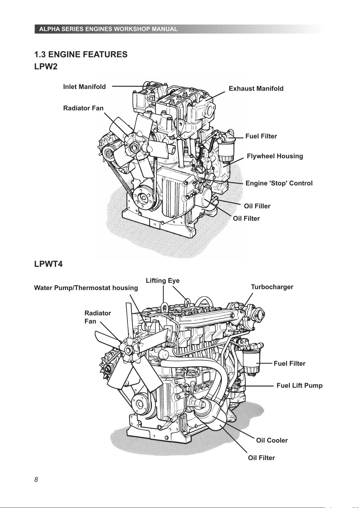
LPWT4
Fuel Lift Pump
Lifting Eye
Turbocharger
Fuel Filter
Radiator
Fan
Oil Cooler
Oil Filter
Water Pump/Thermostat housing
1.3 ENGINE FEATURES
LPW2
Inlet Manifold
Exhaust Manifold
Fuel Filter
Oil Filter
Oil Filler
Engine 'Stop' Control
Radiator Fan
Flywheel Housing
All manuals and user guides at all-guides.com
Page 9
ALPHA SERIES ENGINES WORKSHOP MANUAL
9
1.4 ENGINE IDENTIFICATION
1.4.1 Nomenclature
LPW2, 3 and 4 - two, three and four cylinder, direct
injection, naturally aspirated water cooled diesel
engines.
LPWT4 - four cylinder, direct injection, turbocharged
water cooled diesel engine.
LPWS2, 3 and 4 - two, three and four cylinder,
indirect injection, naturally aspirated water cooled
diesel engines.
LPWST4 - four cylinder, indirect injection,
turbocharged water cooled diesel engine.
1.4.2 Build Information
The engines within each range have been
assembled to predetermined configurations and
where the build number is preceded by a '9' this
indicates that the engine is either of a non-standard
configuration, or contains non-standard parts or
accessories.
When new parts are required for such a build it is
suggested that reference be made to Lister Petter
Power Systems to determine the exact engine
specification and which parts are non-standard.
Where the engine serial number contains a 'G', for
example GLPW3, this denotes the engine was built
into a generating set by Lister Petter Power Systems.
A full list of builds is given in "7. Engine Build
Details".
1.4.3 Engine Serial Number
The engine serial number is stamped on a plate
attached to the engine.
It is necessary to identify the type and build of
each engine to enable the correct maintenance
procedures, as described later in this publication,
to be carried out.
An example number is shown below:
06 00123 LPW3 A 01
06 ............. Year of manufacture code (06 = 2006)
00123 ................... Consecutive number of engine
LPW3 .............................. Model (T = turbocharger
,
S = indirect injection, G = gas fuelled)
A ....................................... Anti clockwise rotation
01 ................................................... Build of engine
All manuals and user guides at all-guides.com
Page 10
ALPHA SERIES ENGINES WORKSHOP MANUAL
10
1.5 BATTERY DETAILS
WARNING
Battery posts, terminals and related accessories
contain lead and lead compounds, chemicals
known to the State of California to cause cancer
and reproductive harm. Wash hands after
handling.
WARNING
Sulphuric acid in battery electrolyte is poisonous,
is strong enough to burn skin, eat holes in
clothing and cause blindness if splashed into
the eyes.
1.5.1 Battery Polarity
The electrical system for all engines is 12 or 24 volt
negative earth (check with meter).
1.5.2 Recommended Battery Type
Heavy Duty Batteries to BS3911:982 or IEC95-1
are recommended for all engine applications.
For temperatures below -18°C (0°F), high discharge,
low resistance Arctic or Alkaline batteries must be
used.
Lister Petter Power Systems recommend that a
battery shouldprovide a minimum cranking period
of 60 seconds from a 70% charged 12 volt battery,
with a minimum voltage at the end of the cranking
period of 8.4 volts (16.8 volts on a 24 volt system).
Note:
Tropical climates apply to those countries or
areas where the average temperature of any
month of the year exceeds 27°C (80°F).
1.5.3 Connecting Batteries
It is most important to ensure that the starter
battery, or batteries, are properly connected and all
connections are tight.
Figure 1.5.3 Battery Connections
A - 12 volt system using four 6 volt batteries connected in series-
parallel.
B - 12 volt system using two 6 volt batteries connected in series.
1.5.4 Connecting a Slave Battery
A slave, or booster battery can be connected in
parallel with the existing battery to aid starting in
cold weather conditions.
WARNING
Heavy duty jumper leads must always be
used and no attempt must be made to use any
others.
WARNING
Do not allow the jumper lead free ends to directly,
or indirectly touch the engine at any time.
1. Connect one end of the jumper lead to the
positive (+) post of the slave battery.
2. Connect the other end of the jumper lead to the
positive (+) post of the battery connected to the
starter motor.
3. Connect one end of the jumper lead to the
negative (-) post of the slave battery.
4. Make the final connection of the negative (-)
cable to a good earth on the engine frame and
away from all the batteries.
1.5.5 Disconnecting a Slave Battery
1. Start the engine.
2. Disconnect the slave battery negative (-) jumper
lead first.
3. Disconnect the remaining jumper leads.
1.5.6 Cold Cranking Battery Requirement
The cold cranking battery requirement table below
is to BS3911 and IEC95-1.
The table below defines the recommended minimum
cold cranking performance required from lead acid
batteries, when tested at an ambient temperature
of -18°C (0°F).
The recommendations made assume that the engine
is filled with the recommended type and grade of
lubricating oil and is not required to start against
high inertia loads such as concrete mixers, tar
boilers, hydraulic pumps, screw pumps and similar.
In these applications, wherever possible, means
should be provided to overcome such loads by the
inclusion of clutches and unloading valves, etc.
All manuals and user guides at all-guides.com
Page 11
ALPHA SERIES ENGINES WORKSHOP MANUAL
11
1.5.7 Recommended Battery Type
Heavy Duty Batteries to BS3911:982 or IEC95-1
are recommended for all applications.
For temperatures below -18°C (0°F), high discharge,
low resistance Arctic or Alkaline batteries must be
used.
System Volts
Ambient Temperature Range °C (°F)
Above 27° (80°)
26° to 1°
(79° to 34°)
0° to -8°
(32° to -18°)
-9° to -18°
(16° to 0°)
LPW2, LPWS2
12V 115A 150A 210A 350A
24V 75A 90A 140A 215A
LPW3, LPWS3
12V 175A 225A 345A 600A
24V 90A 105A 160A 285A
LPW4, LPWT4, LPWS4, LPWST4
12V 190A 255A 380A 670A
24V 75A 105A 160A 300A
Ambient Temperature Range °C (°F)
30° to 5°
(86° to 41°)
4° to -15°
(39° to 5°)
-16° to -25° (3°
to -13°)
-26° to -32°
(-15° to -26°)
Below -32°
(-26°)
LPW, LPWS
A-D
B-D-F
C-D-I C-D-I-G C-D-I-G-H
LPWT4 B-D-F-I
1.15.7.1 Table Code
A. 15W/40 Lubricating oil in the sump.
B. 10W/30 Lubricating oil in the sump.
C. 5W/20 Lubricating oil in the sump.
D. 12 volt starting.
E. Air inlet manifold heater energised while cranking.
F. High discharge, low resistance artic type or alkaline batteries.
G. Heating of the engine and batteries in a housing or engine room.
H. Air inlet manifold heater energised for preheat and while cranking.
1.5.8 Cold Starting Performance
The figures given in the table below are for bare
engines only.
Lister Petter Power Systems recommend that a
battery shouldprovide a minimum cranking period
of 60 seconds from a 70% charged 12 volt battery,
with a minimum voltage at the end of the cranking
period of 8.4 volts (16.8 volts on a 24 volt system).
All manuals and user guides at all-guides.com
all-guides.com
Page 12
ALPHA SERIES ENGINES WORKSHOP MANUAL
12
2.1 PRELIMINARY INSTRUCTIONS
WARNING
Maintenance must be performed by qualied
persons who are conversant with the hazards
of fuels, electricity and machinery.
Before commencing any work on the engine read
the "Safety Precautions and Safe Working Practices"
at the front of this manual.
Dismantling and Rebuilding
When the engine is being dismantled all items must
be identied and retained in their respective cylinder
orientation and all related components must be
treated similarly.
The instructions given deal with in dividual
components and it may be necessary to remove
others before the relevant instructions can be
carried out.
a. Disconnect or isolate any non-electric starting
systems.
b. Disconnect and remove the battery.
c. Drain the diesel fuel and lubricating oil.
d. Drain the coolant.
e. Disconnect all services.
f. Remove any accessories or components that
may be susceptible to damage when the engine
is turned out of its normal plane.
WARNING
Do not attempt to remove the fuel injection pumps
without referring to the relevant instructions.
WARNING
These engines are tted with hydraulic tappets
therefore it is important to follow the procedures
given.
Because of the various engine congurations, and
installations in which the engine can be tted, it is not
possible to give detailed instruction for each one.
Tightening torques are included in the text as
necessary and in table format in "05.5 Spanner
Torques".
When assembling the engine, use the same type
of lubricating oil as used in the engine to spray all
moving parts during assembly. All bearings and
bushes must be well lubricated during assembly.
Renew all joints, gaskets, connecting rod nuts and
bolts and the cylinder head bolts.
2.2 THE AIR CLEANER
Plastic air cleaners have been available since
March 2000 and these complement the existing
sheet metal types.
Every effort should be taken to ensure that the air
cleaner draws in combustion air at the prevailing
ambient temperature. Any increase in combustion
air temperature above the standard engine
reference condition of 25°C (77°F) will incur an
engine derate factor.
2.2.1 The Light Duty Air Cleaner
The industrial type has a replaceable paper
element, and the marine type a serviceable foam
element.
The snout is normally tted lying horizontal and
pointing towards the gear end although the cleaner
itself can be rotated through 360°.
1. Release the three cover clips (A).
2. Lift off the cover (B).
3. Lift out the element (C).
4. Industrial Engines:
a. Fit a new paper element.
Figure 2.2.1 Light Duty Air Cleaner
2.2.2 The Cyclonic Air Cleaner
A cyclonic air cleaner can be remote or engine
mounted over the ywheel housing, both are
connected to the engine by a moulded rubber hose
secured by jubilee clips.
Regularly remove the dust cap (A) and empty all
the dust
2. ENGINE SERVICING AND ADJUSTMENTS
All manuals and user guides at all-guides.com
Page 13
ALPHA SERIES ENGINES WORKSHOP MANUAL
13
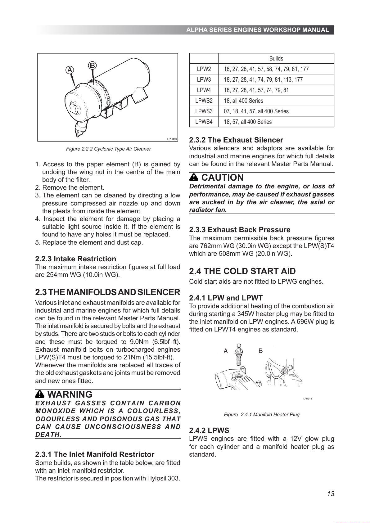
Figure 2.2.2 Cyclonic Type Air Cleaner
1. Access to the paper element (B) is gained by
undoing the wing nut in the centre of the main
body of the lter.
2. Remove the element.
3. The element can be cleaned by directing a low
pressure compressed air nozzle up and down
the pleats from inside the element.
4. Inspect the element for damage by placing a
suitable light source inside it. If the element is
found to have any holes it must be replaced.
5. Replace the element and dust cap.
2.2.3 Intake Restriction
The maximum intake restriction gures at full load
are 254mm WG (10.0in WG).
2.3 THE MANIFOLDS AND SILENCER
Various inlet and exhaust manifolds are available for
industrial and marine engines for which full details
can be found in the relevant Master Parts Manual.
The inlet manifold is secured by bolts and the exhaust
by studs. There are two studs or bolts to each cylinder
and these must be torqued to 9.0Nm (6.5lbf ft).
Exhaust manifold bolts on turbocharged engines
LPW(S)T4 must be torqued to 21Nm (15.5lbf-ft).
Whenever the manifolds are replaced all traces of
the old exhaust gaskets and joints must be removed
and new ones tted.
WARNING
EX HA U ST GA SS ES C O N T AI N CA R BO N
MON O XID E WH I CH IS A CO LOUR L ESS,
OD OURLESS AND POISONOU S G AS THAT
CA N CAU S E UN C ON S CIO USN ESS A N D
DEATH.
2.3.1 The Inlet Manifold Restrictor
Some builds, as shown in the table below, are tted
with an inlet manifold restrictor.
The restrictor is secured in position with Hylosil 303.
Builds
LPW2 18, 27, 28, 41, 57, 58, 74, 79, 81, 177
LPW3 18, 27, 28, 41, 74, 79, 81, 113, 177
LPW4 18, 27, 28, 41, 57, 74, 79, 81
LPWS2 18, all 400 Series
LPWS3 07, 18, 41, 57, all 400 Series
LPWS4 18, 57, all 400 Series
2.3.2 The Exhaust Silencer
Various silencers and adaptors are available for
industrial and marine engines for which full details
can be found in the relevant Master Parts Manual.
CAUTION
Detrimental damage to the engine, or loss of
performance, may be caused if exhaust gasses
are sucked in by the air cleaner, the axial or
radiator fan.
2.3.3 Exhaust Back Pressure
The maximum permissible back pressure gures
are 762mm WG (30.0in WG) except the LPW(S)T4
which are 508mm WG (20.0in WG).
2.4 THE COLD START AID
Cold start aids are not tted to LPWG engines.
2.4.1 LPW and LPWT
To provide additional heating of the combustion air
during starting a 345W heater plug may be tted to
the inlet manifold on LPW engines. A 696W plug is
tted on LPWT4 engines as standard.
Figure 2.4.1 Manifold Heater Plug
2.4.2 LPWS
LPWS engines are tted with a 12V glow plug
for each cylinder and a manifold heater plug as
standard.
All manuals and user guides at all-guides.com
Page 14
ALPHA SERIES ENGINES WORKSHOP MANUAL
14
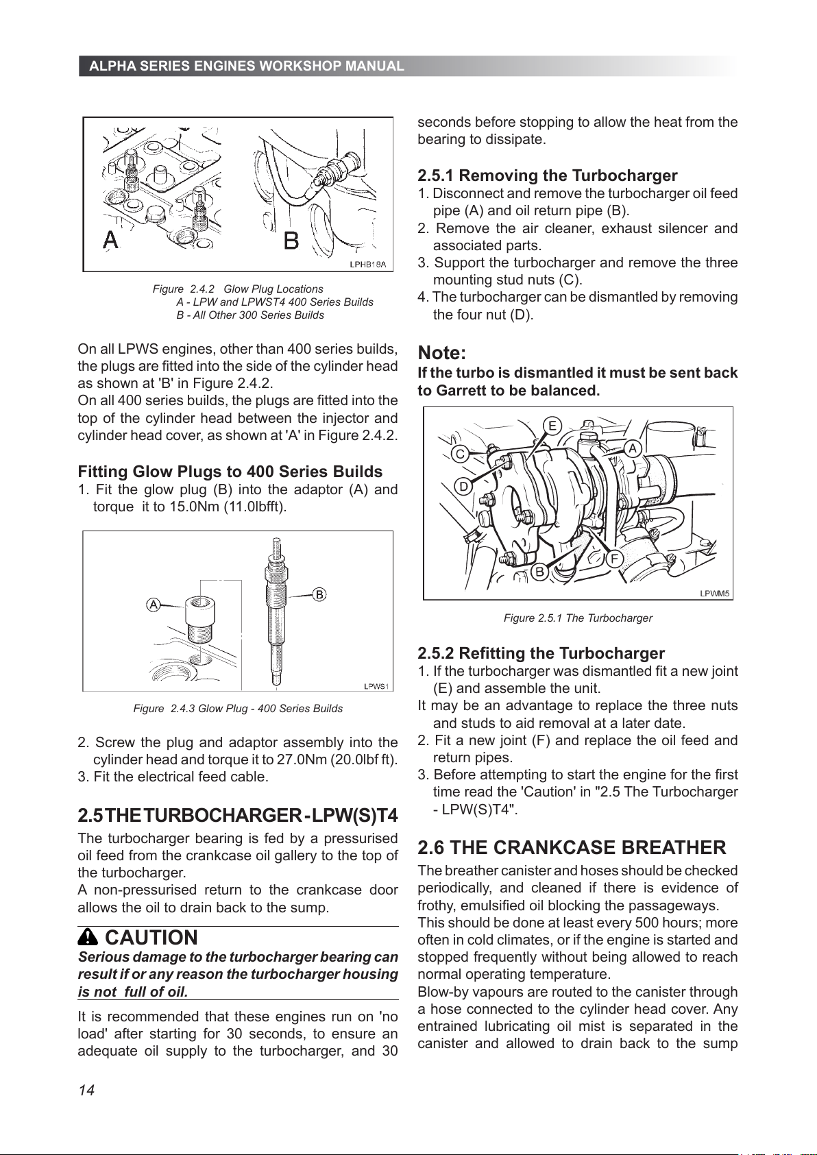
Figure 2.4.2 Glow Plug Locations
A - LPW and LPWST4 400 Series Builds
B - All Other 300 Series Builds
On all LPWS engines, other than 400 series builds,
the plugs are tted into the side of the cylinder head
as shown at 'B' in Figure 2.4.2.
On all 400 series builds, the plugs are tted into the
top of the cylinder head between the injector and
cylinder head cover, as shown at 'A' in Figure 2.4.2.
Fitting Glow Plugs to 400 Series Builds
1. Fit the glow plug (B) into the adaptor (A) and
torque it to 15.0Nm (11.0lbfft).
Figure 2.4.3 Glow Plug - 400 Series Builds
2. Screw the plug and adaptor assembly into the
cylinder head and torque it to 27.0Nm (20.0lbf ft).
3. Fit the electrical feed cable.
2.5 THE TURBOCHARGER - LPW(S)T4
The turbocharger bearing is fed by a pressurised
oil feed from the crankcase oil gallery to the top of
the turbocharger.
A non-pressurised return to the crankcase door
allows the oil to drain back to the sump.
CAUTION
Serious damage to the turbocharger bearing can
result if or any reason the turbocharger housing
is not full of oil.
It is recommended that these engines run on 'no
load' after starting for 30 seconds, to ensure an
adequate oil supply to the turbocharger, and 30
seconds before stopping to allow the heat from the
bearing to dissipate.
2.5.1 Removing the Turbocharger
1. Disconnect and remove the turbocharger oil feed
pipe (A) and oil return pipe (B).
2. Remove the air cleaner, exhaust silencer and
associated parts.
3. Support the turbocharger and remove the three
mounting stud nuts (C).
4. The turbocharger can be dismantled by removing
the four nut (D).
Note:
If the turbo is dismantled it must be sent back
to Garrett to be balanced.
Figure 2.5.1 The Turbocharger
2.5.2 Retting the Turbocharger
1. If the turbocharger was dismantled t a new joint
(E) and assemble the unit.
It may be an advantage to replace the three nuts
and studs to aid removal at a later date.
2. Fit a new joint (F) and replace the oil feed and
return pipes.
3. Before attempting to start the engine for the rst
time read the 'Caution' in "2.5 The Turbocharger
- LPW(S)T4".
2.6 THE CRANKCASE BREATHER
The breather canister and hoses should be checked
periodically, and cleaned if there is evidence of
frothy, emulsied oil blocking the passageways.
This should be done at least every 500 hours; more
often in cold climates, or if the engine is started and
stopped frequently without being allowed to reach
normal operating temperature.
Blow-by vapours are routed to the canister through
a hose connected to the cylinder head cover. Any
entrained lubricating oil mist is separated in the
canister and allowed to drain back to the sump
All manuals and user guides at all-guides.com
Page 15
ALPHA SERIES ENGINES WORKSHOP MANUAL
15
2.7.3 Starter Motor Terminal Torques
Starter Motor
Battery +
Terminal 1
Link
Terminal 2
Lucas/Magnetti Marrelli
(discontinued)
4.0-4.2 3.1-3.2
2.95-3.01 2.3-2.4
Denso Starter
5.89-11.77 5.89-11.77
4.34-8.68 4.34-8.68
UniPoint Starter
5.89-11.77 5.89-11.77
4.34-8.68 4.34-8.68
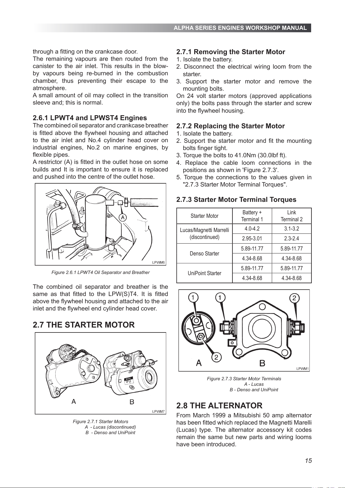
Figure 2.7.3 Starter Motor Terminals
A - Lucas
B - Denso and UniPoint
2.8 THE ALTERNATOR
From March 1999 a Mitsubishi 50 amp alternator
has been tted which replaced the Magnetti Marelli
(Lucas) type. The alternator accessory kit codes
remain the same but new parts and wiring looms
have been introduced.
through a tting on the crankcase door.
The remaining vapours are then routed from the
canister to the air inlet. This results in the blow-
by vapours being re-burned in the combustion
chamber, thus preventing their escape to the
atmosphere.
A small amount of oil may collect in the transition
sleeve and; this is normal.
2.6.1 LPWT4 and LPWST4 Engines
The combined oil separator and crankcase breather
is tted above the ywheel housing and attached
to the air inlet and No.4 cylinder head cover on
industrial engines, No.2 on marine engines, by
exible pipes.
A restrictor (A) is tted in the outlet hose on some
builds and It is important to ensure it is replaced
and pushed into the centre of the outlet hose.
Figure 2.6.1 LPWT4 Oil Separator and Breather
The combined oil separator and breather is the
same as that tted to the LPW(S)T4. It is tted
above the ywheel housing and attached to the air
inlet and the ywheel end cylinder head cover.
2.7 THE STARTER MOTOR
Figure 2.7.1 Starter Motors
A - Lucas (discontinued)
B - Denso and UniPoint
2.7.1 Removing the Starter Motor
1. Isolate the battery.
2. Disconnect the electrical wiring loom from the
starter.
3. Support the starter motor and remove the
mounting bolts.
On 24 volt starter motors (approved applications
only) the bolts pass through the starter and screw
into the ywheel housing.
2.7.2 Replacing the Starter Motor
1. Isolate the battery.
2. Support the starter motor and t the mounting
bolts nger tight.
3. Torque the bolts to 41.0Nm (30.0lbf ft).
4. Replace the cable loom connections in the
positions as shown in 'Figure 2.7.3'.
5. Torque the connections to the values given in
"2.7.3 Starter Motor Terminal Torques".
All manuals and user guides at all-guides.com
Page 16
ALPHA SERIES ENGINES WORKSHOP MANUAL
16
If an alternator is not required, a jockey pulley is
tted in its place.
The alternator is belt driven at the gear cover end
by a V-ribbed belt and the alternator to engine
speed ratio and output is constant for all engines.
An additional 100A earth return, or 55A insulated
return, alternator to power on board equipment is
available as an option for some marine builds.
Industrial - 12 volt negative earth with an engine
mounted 45A or 50A battery charging alternator.
CAUTION
When running the engine for battery charging
purposes the engine speed should be set to a
minimum of 1200r/min.
2.8.1 Terminal Identication
Terminal Mitsubishi Magnetti Marelli
Battery + B +
Warning light L IND
Phase tape P W
Regulator
reference
R not available
WARNING
The Mitsubishi 'R' terminal is for the alternator
reference circuit and must be wired into the
circuit.
2.8.2 Removing the Alternator
These instructions are specic to a Marelli Magnetti
alternator but also apply in general to the Mitsubishi
type.
1. Isolate the battery.
2. Remove the cable loom plug from the alternator
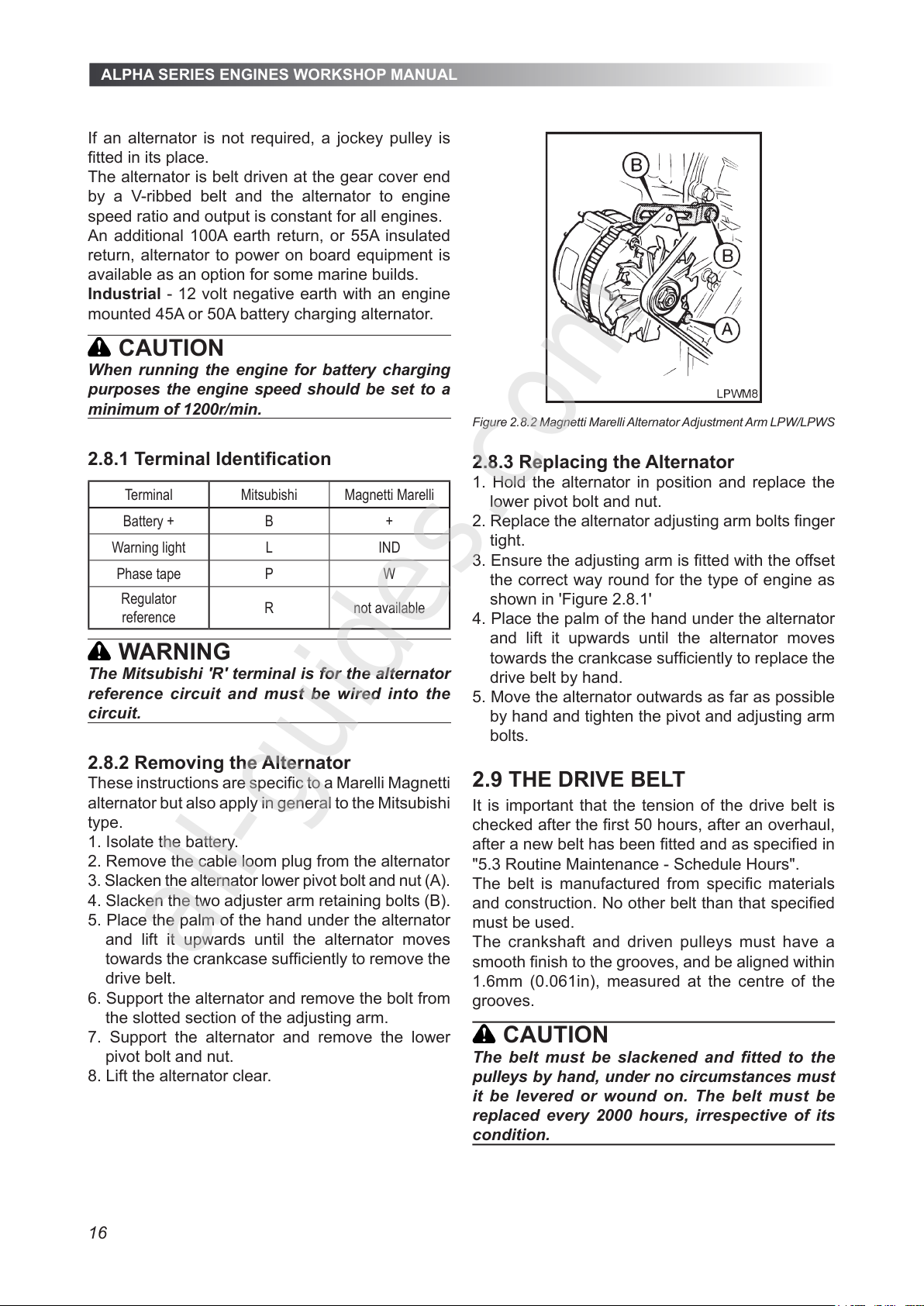
3. Slacken the alternator lower pivot bolt and nut (A).
4. Slacken the two adjuster arm retaining bolts (B).
5. Place the palm of the hand under the alternator
and lift it upwards until the alternator moves
towards the crankcase sufciently to remove the
drive belt.
6. Support the alternator and remove the bolt from
the slotted section of the adjusting arm.
7. Support the alternator and remove the lower
pivot bolt and nut.
8. Lift the alternator clear.
Figure 2.8.2 Magnetti Marelli Alternator Adjustment Arm LPW/LPWS
2.8.3 Replacing the Alternator
1. Hold the alternator in position and replace the
lower pivot bolt and nut.
2. Replace the alternator adjusting arm bolts nger
tight.
3. Ensure the adjusting arm is tted with the offset
the correct way round for the type of engine as
shown in 'Figure 2.8.1'
4. Place the palm of the hand under the alternator
and lift it upwards until the alternator moves
towards the crankcase sufciently to replace the
drive belt by hand.
5. Move the alternator outwards as far as possible
by hand and tighten the pivot and adjusting arm
bolts.
2.9 THE DRIVE BELT
It is important that the tension of the drive belt is
checked after the rst 50 hours, after an overhaul,
after a new belt has been tted and as specied in
"5.3 Routine Maintenance - Schedule Hours".
The belt is manufactured from specic materials
and construction. No other belt than that specied
must be used.
The crankshaft and driven pulleys must have a
smooth nish to the grooves, and be aligned within
1.6mm (0.061in), measured at the centre of the
grooves.
CAUTION
The belt must be slackened and tted to the
pulleys by hand, under no circumstances must
it be levered or wound on. The belt must be
replaced every 2000 hours, irrespective of its
condition.
All manuals and user guides at all-guides.com
all-guides.com
Page 17
ALPHA SERIES ENGINES WORKSHOP MANUAL
17
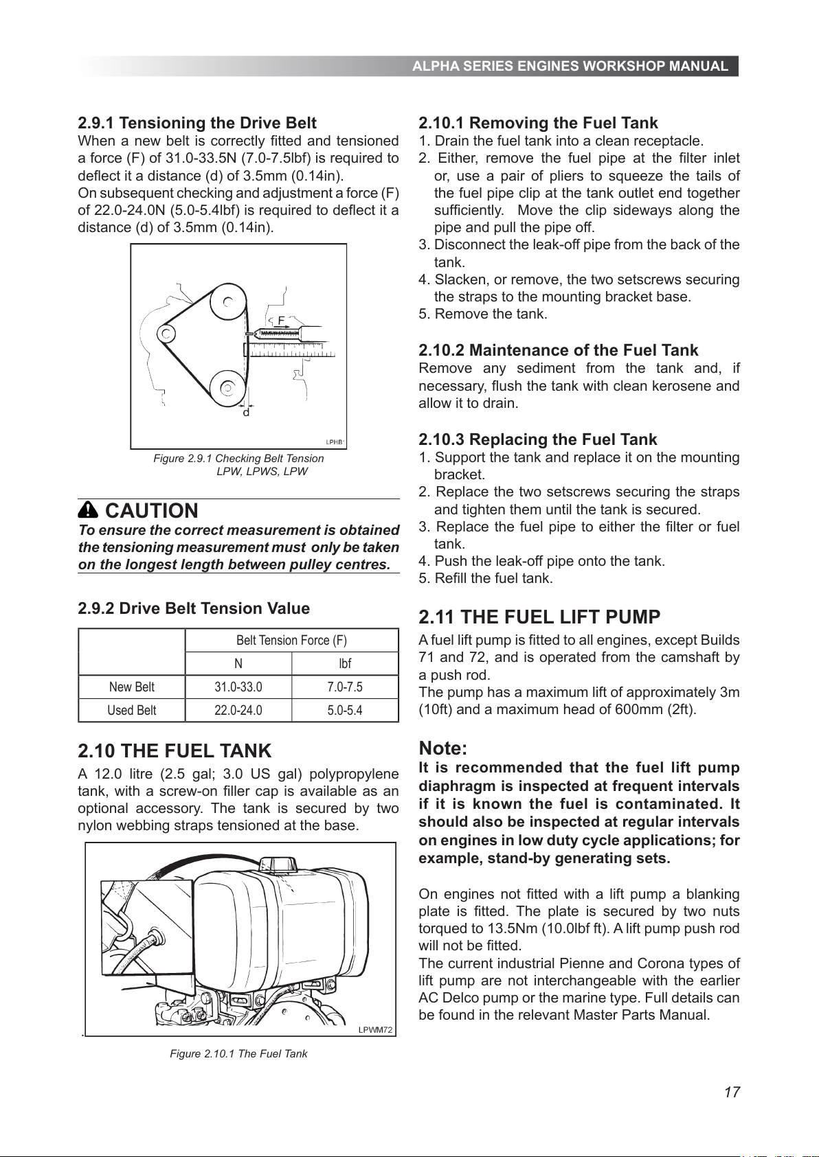
2.9.1 Tensioning the Drive Belt
When a new belt is correctly tted and tensioned
a force (F) of 31.0-33.5N (7.0-7.5lbf) is required to
deect it a distance (d) of 3.5mm (0.14in).
On subsequent checking and adjustment a force (F)
of 22.0-24.0N (5.0-5.4lbf) is required to deect it a
distance (d) of 3.5mm (0.14in).
Figure 2.9.1 Checking Belt Tension
LPW, LPWS, LPW
CAUTION
To ensure the correct measurement is obtained
the tensioning measurement must only be taken
on the longest length between pulley centres.
2.9.2 Drive Belt Tension Value
Belt Tension Force (F)
N lbf
New Belt 31.0-33.0 7.0-7.5
Used Belt 22.0-24.0 5.0-5.4
2.10 THE FUEL TANK
A 12.0 litre (2.5 gal; 3.0 US gal) polypropylene
tank, with a screw-on ller cap is available as an
optional accessory. The tank is secured by two
nylon webbing straps tensioned at the base.
.
Figure 2.10.1 The Fuel Tank
2.10.1 Removing the Fuel Tank
1. Drain the fuel tank into a clean receptacle.
2. Either, remove the fuel pipe at the lter inlet
or, use a pair of pliers to squeeze the tails of
the fuel pipe clip at the tank outlet end together
sufciently. Move the clip sideways along the
pipe and pull the pipe off.
3. Disconnect the leak-off pipe from the back of the
tank.
4. Slacken, or remove, the two setscrews securing
the straps to the mounting bracket base.
5. Remove the tank.
2.10.2 Maintenance of the Fuel Tank
Remove any sediment from the tank and, if
necessary, ush the tank with clean kerosene and
allow it to drain.
2.10.3 Replacing the Fuel Tank
1. Support the tank and replace it on the mounting
bracket.
2. Replace the two setscrews securing the straps
and tighten them until the tank is secured.
3. Replace the fuel pipe to either the lter or fuel
tank.
4. Push the leak-off pipe onto the tank.
5. Rell the fuel tank.
2.11 THE FUEL LIFT PUMP
A fuel lift pump is tted to all engines, except Builds
71 and 72, and is operated from the camshaft by
a push rod.
The pump has a maximum lift of approximately 3m
(10ft) and a maximum head of 600mm (2ft).
Note:
It is recommended that the fuel lift pump
diaphragm is inspected at frequent intervals
if it is known the fuel is contaminated. It
should also be inspected at regular intervals
on engines in low duty cycle applications; for
example, stand-by generating sets.
On engines not tted with a lift pump a blanking
plate is tted. The plate is secured by two nuts
torqued to 13.5Nm (10.0lbf ft). A lift pump push rod
will not be tted.
The current industrial Pienne and Corona types of
lift pump are not interchangeable with the earlier
AC Delco pump or the marine type. Full details can
be found in the relevant Master Parts Manual.
All manuals and user guides at all-guides.com
Page 18
ALPHA SERIES ENGINES WORKSHOP MANUAL
18
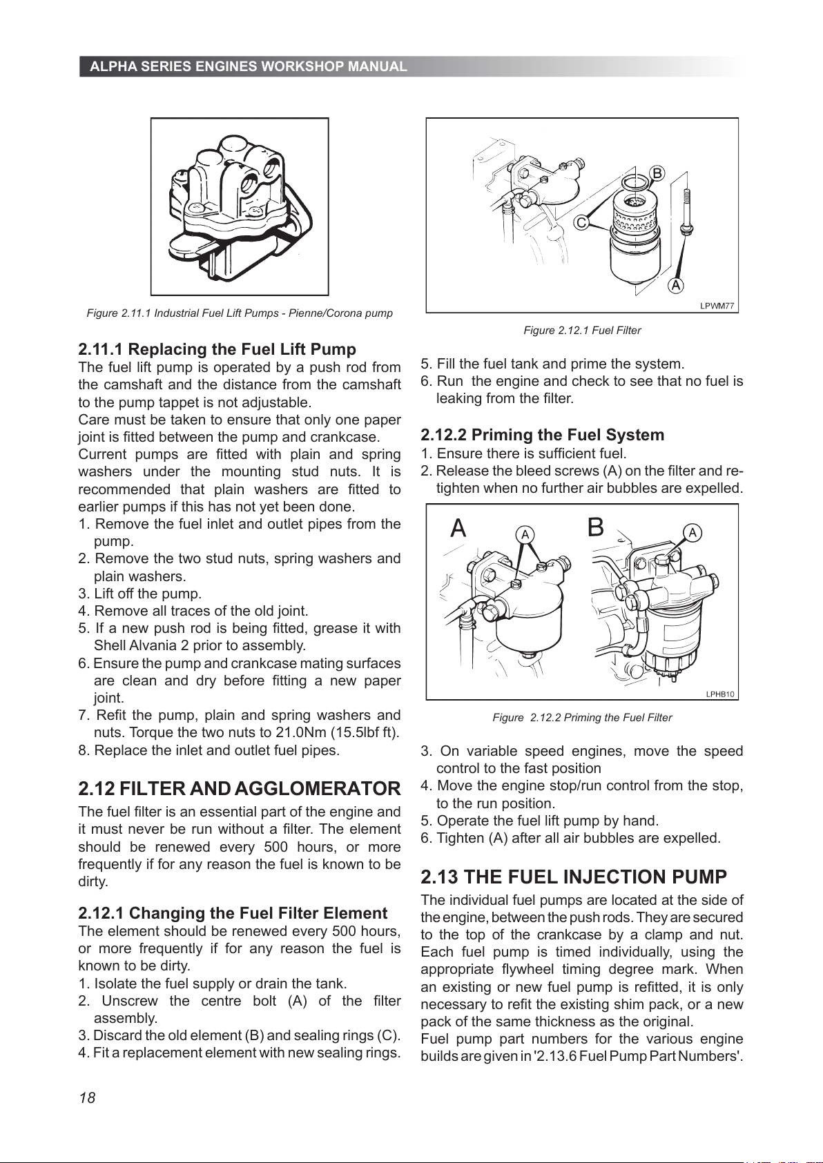
Figure 2.11.1 Industrial Fuel Lift Pumps - Pienne/Corona pump
2.11.1 Replacing the Fuel Lift Pump
The fuel lift pump is operated by a push rod from
the camshaft and the distance from the camshaft
to the pump tappet is not adjustable.
Care must be taken to ensure that only one paper
joint is tted between the pump and crankcase.
Current pumps are tted with plain and spring
washers under the mounting stud nuts. It is
recommended that plain washers are tted to
earlier pumps if this has not yet been done.
1. Remove the fuel inlet and outlet pipes from the
pump.
2. Remove the two stud nuts, spring washers and
plain washers.
3. Lift off the pump.
4. Remove all traces of the old joint.
5. If a new push rod is being tted, grease it with
Shell Alvania 2 prior to assembly.
6. Ensure the pump and crankcase mating surfaces
are clean and dry before tting a new paper
joint.
7. Ret the pump, plain and spring washers and
nuts. Torque the two nuts to 21.0Nm (15.5lbf ft).
8. Replace the inlet and outlet fuel pipes.
2.12 FILTER AND AGGLOMERATOR
The fuel lter is an essential part of the engine and
it must never be run without a lter. The element
should be renewed every 500 hours, or more
frequently if for any reason the fuel is known to be
dirty.
2.12.1 Changing the Fuel Filter Element
The element should be renewed every 500 hours,
or more frequently if for any reason the fuel is
known to be dirty.
1. Isolate the fuel supply or drain the tank.
2. Unscrew the centre bolt (A) of the lter
assembly.
3. Discard the old element (B) and sealing rings (C).
4. Fit a replacement element with new sealing rings.
Figure 2.12.1 Fuel Filter
5. Fill the fuel tank and prime the system.
6. Run the engine and check to see that no fuel is
leaking from the lter.
2.12.2 Priming the Fuel System
1. Ensure there is sufcient fuel.
2. Release the bleed screws (A) on the lter and re-
tighten when no further air bubbles are expelled.
Figure 2.12.2 Priming the Fuel Filter
3. On variable speed engines, move the speed
control to the fast position
4. Move the engine stop/run control from the stop,
to the run position.
5. Operate the fuel lift pump by hand.
6. Tighten (A) after all air bubbles are expelled.
2.13 THE FUEL INJECTION PUMP
The individual fuel pumps are located at the side of
the engine, between the push rods. They are secured
to the top of the crankcase by a clamp and nut.
Each fuel pump is timed individually, using the
appropriate ywheel timing degree mark. When
an existing or new fuel pump is retted, it is only
necessary to ret the existing shim pack, or a new
pack of the same thickness as the original.
Fuel pump part numbers for the various engine
builds are given in '2.13.6 Fuel Pump Part Numbers'.
All manuals and user guides at all-guides.com
Page 19
ALPHA SERIES ENGINES WORKSHOP MANUAL
19
2.13.1 Removing a Fuel Pump
To retain the governor setting leave one fuel pump
in position.
1. Isolate the fuel supply.
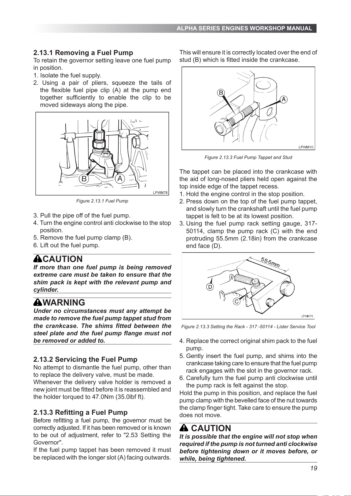
2. Using a pair of pliers, squeeze the tails of
the exible fuel pipe clip (A) at the pump end
together sufciently to enable the clip to be
moved sideways along the pipe.
Figure 2.13.1 Fuel Pump
3. Pull the pipe off of the fuel pump.
4. Turn the engine control anti clockwise to the stop
position.
5. Remove the fuel pump clamp (B).
6. Lift out the fuel pump.
CAUTION
If more than one fuel pump is being removed
extreme care must be taken to ensure that the
shim pack is kept with the relevant pump and
cylinder.
WARNING
Under no circumstances must any attempt be
made to remove the fuel pump tappet stud from
the crankcase. The shims tted between the
steel plate and the fuel pump ange must not
be removed or added to.
2.13.2 Servicing the Fuel Pump
No attempt to dismantle the fuel pump, other than
to replace the delivery valve, must be made.
Whenever the delivery valve holder is removed a
new joint must be tted before it is reassembled and
the holder torqued to 47.0Nm (35.0lbf ft).
2.13.3 Retting a Fuel Pump
Before retting a fuel pump, the governor must be
correctly adjusted. If it has been removed or is known
to be out of adjustment, refer to "2.53 Setting the
Governor".
If the fuel pump tappet has been removed it must
be replaced with the longer slot (A) facing outwards.
This will ensure it is correctly located over the end of
stud (B) which is tted inside the crankcase.
Figure 2.13.3 Fuel Pump Tappet and Stud
The tappet can be placed into the crankcase with
the aid of long-nosed pliers held open against the
top inside edge of the tappet recess.
1. Hold the engine control in the stop position.
2. Press down on the top of the fuel pump tappet,
and slowly turn the crankshaft until the fuel pump
tappet is felt to be at its lowest position.
3. Using the fuel pump rack setting gauge, 317-
50114, clamp the pump rack (C) with the end
protruding 55.5mm (2.18in) from the crankcase
end face (D).
Figure 2.13.3 Setting the Rack - 317 -50114 - Lister Service Tool
4. Replace the correct original shim pack to the fuel
pump.
5. Gently insert the fuel pump, and shims into the
crankcase taking care to ensure that the fuel pump
rack engages with the slot in the governor rack.
6. Carefully turn the fuel pump anti clockwise until
the pump rack is felt against the stop.
Hold the pump in this position, and replace the fuel
pump clamp with the bevelled face of the nut towards
the clamp nger tight. Take care to ensure the pump
does not move.
CAUTION
It is possible that the engine will not stop when
required if the pump is not turned anti clockwise
before tightening down or it moves before, or
while, being tightened.
All manuals and user guides at all-guides.com
Page 20
ALPHA SERIES ENGINES WORKSHOP MANUAL
20
7. Torque the nut to 34.0Nm (25.0lbf ft).
8. Replace the fuel pipes.
9. To ensure the control lever is positively stopped by
the control lever stop screw and not the fuel pump
stops refer to "2.55 Setting the Stop/Run Lever".
2.13.4 Fuel Pump Shims
The shims tted by the pump manufacturer between
the pump ange and the steel plate must not be
removed or added to.
2.13.5 Fuel Pump Shim Packs
Extreme care must be taken to ensure that the
individual shim packs that are tted between each
fuel pump plate and the crankcase are retained with
their original respective cylinder.
The colour coded shims are available in three
sizes:
Green 0.075mm (0.003in).
Slate blue or white 0.125mm (0.005in).
Black 0.250mm (0.010in).
2.14 FUEL PUMP TIMING
It will only be necessary to carry out pump timing
if the original shims have been lost or mixed with
those of another pump.
The following shim combinations are used to vary
the timing.
Change Shim Combination
1º 1 Green
2º 1 Green and 1 slate blue or white
3º 1 Green and 1 black
4º 2 Green and 1 black
To advance the timing - remove shims.
To retard the timing - add shims.
2.14.1 Piston Displacement Method
The following sequence of operations must be
repeated for each pump as necessary, using the
appropriate ring degree mark on the ywheel.
1. Rotate the piston to TDC on the ring stroke.
2. Use a suitable probe resting on top of the piston, on
the gudgeon pin axis, to accurately determine TDC.
3. Rotate the ywheel clockwise to beyond the
specied piston displacement, as given in "2.15
Fuel Pump Timing Values", from TDC.
The correct gure for the type and build of engine
must be used.
4. Carefully rotate the ywheel anti clockwise until
the correct piston displacement gure is reached.
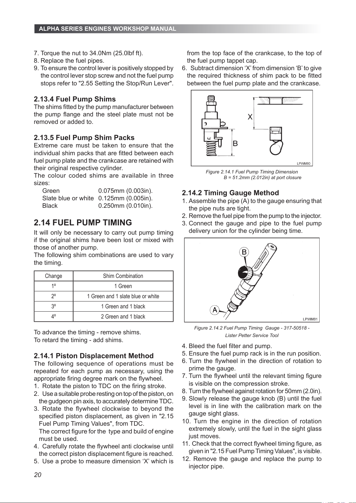
5. Use a probe to measure dimension ‘X’ which is
from the top face of the crankcase, to the top of
the fuel pump tappet cap.
6. Subtract dimension ‘X’ from dimension ‘B’ to give
the required thickness of shim pack to be tted
between the fuel pump plate and the crankcase.
Figure 2.14.1 Fuel Pump Timing Dimension
B = 51.2mm (2.012in) at port closure
2.14.2 Timing Gauge Method
1. Assemble the pipe (A) to the gauge ensuring that
the pipe nuts are tight.
2. Remove the fuel pipe from the pump to the injector.
3. Connect the gauge and pipe to the fuel pump
delivery union for the cylinder being time.
Figure 2.14.2 Fuel Pump Timing Gauge - 317-50518 -
Lister Petter Service Tool
4. Bleed the fuel lter and pump.
5. Ensure the fuel pump rack is in the run position.
6. Turn the ywheel in the direction of rotation to
prime the gauge.
7. Turn the ywheel until the relevant timing gure
is visible on the compression stroke.
8. Turn the ywheel against rotation for 50mm (2.0in).
9. Slowly release the gauge knob (B) until the fuel
level is in line with the calibration mark on the
gauge sight glass.
10. Turn the engine in the direction of rotation
extremely slowly, until the fuel in the sight glass
just moves.
11. Check that the correct ywheel timing gure, as
given in "2.15 Fuel Pump Timing Values", is visible.
12. Remove the gauge and replace the pump to
injector pipe.
All manuals and user guides at all-guides.com
Page 21
ALPHA SERIES ENGINES WORKSHOP MANUAL
21
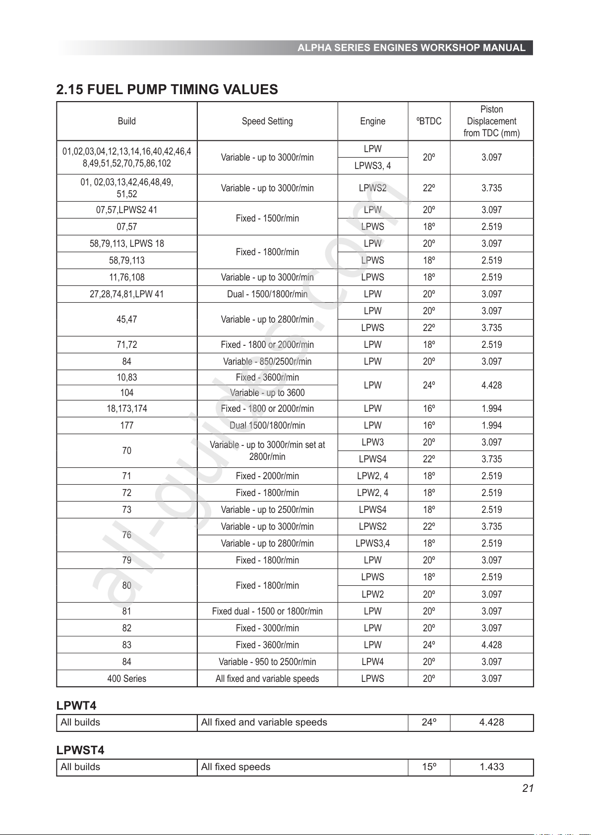
2.15 FUEL PUMP TIMING VALUES
Build Speed Setting Engine ºBTDC
Piston
Displacement
from TDC (mm)
01,02,03,04,12,13,14,16,40,42,46,4
8,49,51,52,70,75,86,102
Variable - up to 3000r/min
LPW
20º 3.097
LPWS3, 4
01, 02,03,13,42,46,48,49,
51,52
Variable - up to 3000r/min LPWS2 22º 3.735
07,57,LPWS2 41
Fixed - 1500r/min
LPW 20º 3.097
07,57 LPWS 18º 2.519
58,79,113, LPWS 18
Fixed - 1800r/min
LPW 20º 3.097
58,79,113 LPWS 18º 2.519
11,76,108 Variable - up to 3000r/min LPWS 18º 2.519
27,28,74,81,LPW 41 Dual - 1500/1800r/min LPW 20º 3.097
45,47 Variable - up to 2800r/min
LPW 20º 3.097
LPWS 22º 3.735
71,72 Fixed - 1800 or 2000r/min LPW 18º 2.519
84 Variable - 850/2500r/min LPW 20º 3.097
10,83 Fixed - 3600r/min
LPW 24º 4.428
104 Variable - up to 3600
18,173,174 Fixed - 1800 or 2000r/min LPW 16º 1.994
177 Dual 1500/1800r/min LPW 16º 1.994
70
Variable - up to 3000r/min set at
2800r/min
LPW3 20º 3.097
LPWS4 22º 3.735
71 Fixed - 2000r/min LPW2, 4 18º 2.519
72 Fixed - 1800r/min LPW2, 4 18º 2.519
73 Variable - up to 2500r/min LPWS4 18º 2.519
76
Variable - up to 3000r/min LPWS2 22º 3.735
Variable - up to 2800r/min LPWS3,4 18º 2.519
79 Fixed - 1800r/min LPW 20º 3.097
80 Fixed - 1800r/min
LPWS 18º 2.519
LPW2 20º 3.097
81 Fixed dual - 1500 or 1800r/min LPW 20º 3.097
82 Fixed - 3000r/min LPW 20º 3.097
83 Fixed - 3600r/min LPW 24º 4.428
84 Variable - 950 to 2500r/min LPW4 20º 3.097
400 Series All xed and variable speeds LPWS 20º 3.097
LPWT4
All builds All xed and variable speeds 24º 4.428
LPWST4
All builds All xed speeds 15º 1.433
All manuals and user guides at all-guides.com
all-guides.com
Page 22
ALPHA SERIES ENGINES WORKSHOP MANUAL
22
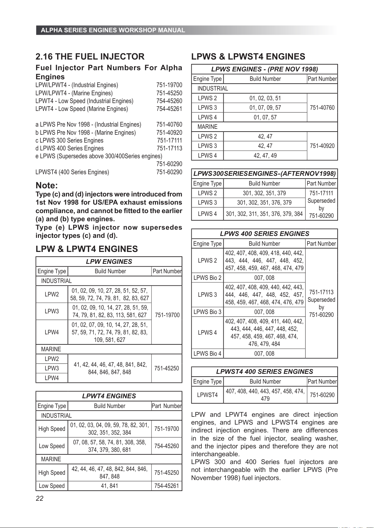
2.16 THE FUEL INJECTOR
Fuel Injector Part Numbers For Alpha
Engines
LPW/LPWT4 - (Industrial Engines) 751-19700
LPW/LPWT4 - (Marine Engines) 751-45250
LPWT4 - Low Speed (Industrial Engines) 754-45260
LPWT4 - Low Speed (Marine Engines) 754-45261
a LPWS Pre Nov 1998 - (Industrial Engines) 751-40760
b LPWS Pre Nov 1998 - (Marine Engines) 751-40920
c LPWS 300 Series Engines 751-17111
d LPWS 400 Series Engines 751-17113
e LPWS (Supersedes above 300/400Series engines)
751-60290
LPWST4 (400 Series Engines) 751-60290
Note:
Type (c) and (d) injectors were introduced from
1st Nov 1998 for US/EPA exhaust emissions
compliance, and cannot be tted to the earlier
(a) and (b) type engines.
Type (e) LPWS injector now supersedes
injector types (c) and (d).
LPW & LPWT4 ENGINES
LPW ENGINES
Engine Type Build Number Part Number
INDUSTRIAL
LPW2
01, 02, 09, 10, 27, 28, 51, 52, 57,
58, 59, 72, 74, 79, 81, 82, 83, 627
751-19700
LPW3
01, 02, 09, 10, 14, 27, 28, 51, 59,
74, 79, 81, 82, 83, 113, 581, 627
LPW4
01, 02, 07, 09, 10, 14, 27, 28, 51,
57, 59, 71, 72, 74, 79, 81, 82, 83,
109, 581, 627
MARINE
LPW2
41, 42, 44, 46, 47, 48, 841, 842,
844, 846, 847, 848
751-45250LPW3
LPW4
LPWT4 ENGINES
Engine Type Build Number Part Number
INDUSTRIAL
High Speed
01, 02, 03, 04, 09, 59, 78, 82, 301,
302, 351, 352, 384
751-19700
Low Speed
07, 08, 57, 58, 74, 81, 308, 358,
374, 379, 380, 681
754-45260
MARINE
High Speed
42, 44, 46, 47, 48, 842, 844, 846,
847, 848
751-45250
Low Speed 41, 841 754-45261
LPWS & LPWST4 ENGINES
LPWS ENGINES - (PRE NOV 1998)
Engine Type Build Number Part Number
INDUSTRIAL
LPWS 2 01, 02, 03, 51
751-40760LPWS 3 01, 07, 09, 57
LPWS 4 01, 07, 57
MARINE
LPWS 2 42, 47
751-40920LPWS 3 42, 47
LPWS 4 42, 47, 49
LPWS 300 SERIES ENGINES - (AFTER NOV 1998)
Engine Type Build Number Part Number
LPWS 2 301, 302, 351, 379 751-17111
Superseded
by
751-60290
LPWS 3 301, 302, 351, 376, 379
LPWS 4 301, 302, 311, 351, 376, 379, 384
LPWS 400 SERIES ENGINES
Engine Type Build Number Part Number
LPWS 2
402, 407, 408, 409, 418, 440, 442,
443, 444, 446, 447, 448, 452,
457, 458, 459, 467, 468, 474, 479
751-17113
Superseded
by
751-60290
LPWS Bio 2 007, 008
LPWS 3
402, 407, 408, 409, 440, 442, 443,
444, 446, 447, 448, 452, 457,
458, 459, 467, 468, 474, 476, 479
LPWS Bio 3 007, 008
LPWS 4
402, 407, 408, 409, 411, 440, 442,
443, 444, 446, 447, 448, 452,
457, 458, 459, 467, 468, 474,
476, 479, 484
LPWS Bio 4 007, 008
LPWST4 400 SERIES ENGINES
Engine Type Build Number Part Number
LPWST4
407, 408, 440, 443, 457, 458, 474,
479
751-60290
LPW and LPWT4 engines are direct injection
engines, and LPWS and LPWST4 engines are
indirect injection engines. There are differences
in the size of the fuel injector, sealing washer,
and the injector pipes and therefore they are not
interchangeable.
LPWS 300 and 400 Series fuel injectors are
not interchangeable with the earlier LPWS (Pre
November 1998) fuel injectors.
All manuals and user guides at all-guides.com
Page 23
ALPHA SERIES ENGINES WORKSHOP MANUAL
23
It is important to maintain the fuel injection
equipment, injection pipes, and unions between the
fuel supply lter and the injector in an absolutely
clean condition. A minute particle of dirt can easily
block an injector nozzle hole and this will give rise
to exhaust smoke, difcult starting, and poor engine
performance.
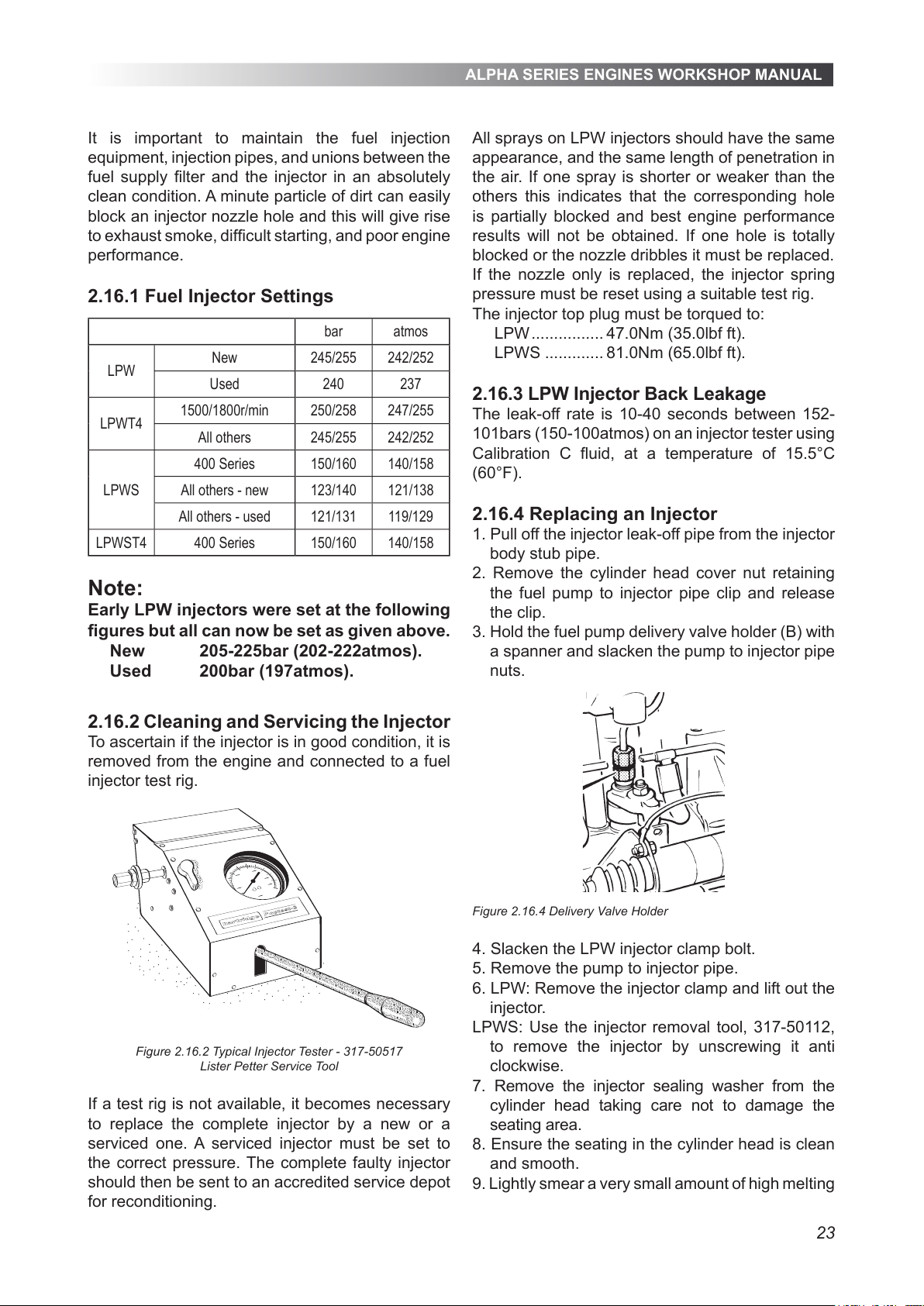
2.16.1 Fuel Injector Settings
bar atmos
LPW
New 245/255 242/252
Used 240 237
LPWT4
1500/1800r/min 250/258 247/255
All others 245/255 242/252
LPWS
400 Series 150/160 140/158
All others - new 123/140 121/138
All others - used 121/131 119/129
LPWST4 400 Series 150/160 140/158
Note:
Early LPW injectors were set at the following
gures but all can now be set as given above.
New 205-225bar (202-222atmos).
Used 200bar (197atmos).
2.16.2 Cleaning and Servicing the Injector
To ascertain if the injector is in good condition, it is
removed from the engine and connected to a fuel
injector test rig.
Figure 2.16.2 Typical Injector Tester - 317-50517
Lister Petter Service Tool
If a test rig is not available, it becomes necessary
to replace the complete injector by a new or a
serviced one. A serviced injector must be set to
the correct pressure. The complete faulty injector
should then be sent to an accredited service depot
for reconditioning.
All sprays on LPW injectors should have the same
appearance, and the same length of penetration in
the air. If one spray is shorter or weaker than the
others this indicates that the corresponding hole
is partially blocked and best engine performance
results will not be obtained. If one hole is totally
blocked or the nozzle dribbles it must be replaced.
If the nozzle only is replaced, the injector spring
pressure must be reset using a suitable test rig.
The injector top plug must be torqued to:
LPW ................ 47.0Nm (35.0lbf ft).
LPWS ............. 81.0Nm (65.0lbf ft).
2.16.3 LPW Injector Back Leakage
The leak-off rate is 10-40 seconds between 152-
101bars (150-100atmos) on an injector tester using
Calibration C uid, at a temperature of 15.5°C
(60°F).
2.16.4 Replacing an Injector
1. Pull off the injector leak-off pipe from the injector
body stub pipe.
2. Remove the cylinder head cover nut retaining
the fuel pump to injector pipe clip and release
the clip.
3. Hold the fuel pump delivery valve holder (B) with
a spanner and slacken the pump to injector pipe
nuts.
Figure 2.16.4 Delivery Valve Holder
4. Slacken the LPW injector clamp bolt.
5. Remove the pump to injector pipe.
6. LPW: Remove the injector clamp and lift out the
injector.
LPWS: Use the injector removal tool, 317-50112,
to remove the injector by unscrewing it anti
clockwise.
7. Remove the injector sealing washer from the
cylinder head taking care not to damage the
seating area.
8. Ensure the seating in the cylinder head is clean
and smooth.
9. Lightly smear a very small amount of high melting
All manuals and user guides at all-guides.com
Page 24
ALPHA SERIES ENGINES WORKSHOP MANUAL
24
point grease to one side of a new injector sealing
washer and place it over the injector nozzle,
greased side rst.
CAUTION
If the injector sealing washer has been used
more than once it may become compressed
causing a leak or damage to the injector seat.
10. LPW: Replace the injector and clamp. Hand
tighten the clamp bolt.
LPWS: Screw in the injector and torque it to
68.0Nm (50.0lbf ft).
11. Replace the pump to injector pipe hand
tightening the nuts.
12. Fit new rubber ‘O’ rings into the recesses on
the cylinder head cover.
13. Replace the pipe clip and torque the nut to
9.0Nm (6.5lbf ft).
14. Torque the LPW injector clamp bolt to 21.0Nm
(15.5lbf ft).
15. Hold the fuel pump delivery valve holder with a
spanner and torque the fuel pipe nuts to 29.0Nm
(21.0lbf ft).
16. Replace the injector leak-off pipe.
LPW engines before those shown below were tted
with injector seal washers 361296, later engines
are tted with seal washer 201-45070.
42 00014 LPWS2
42 00041 LPWS3
42 00685 LPWS4
41 00324 LPW2
41 00001 LPW
41 00570 LPW4
2.17 THE OIL SYSTEM
The lubricating oil sump forms an integral part of
the cast iron crankcase and has two drain plugs;
one at the gear end and the other on the lter side
of the crankcase.
The oil ller and dipstick are both located on the
crankcase door or cylinder head.
The oil pump, shown in "Figure 2.24.3", is gear
driven from the camshaft and is tted with a
removable strainer and oil relief valve; the relief
valve setting is preset.
Oil in the sump is drawn into the pump through
the oil strainer and is then delivered by the pump
through a drilling in the crankcase to the hole
nearest the outside of the cartridge type oil lter
base.
Filtered pressure oil passes through the centre
of the lter into the oil gallery in the crankcase
door and from the oil gallery it is delivered to the
crankshaft and bearings.
The connecting rod big end bearings are pressure
fed through internal drilling in the crankshaft from
the supply to the main bearings.
Splash oil lubricates the gears, governor, camshaft
and the underside of the pistons. On some engines
high speed oil jets supply oil under pressure to the
pistons and governor gears.
An internal crankcase drilling provides an oil feed
to the hydraulic tappets.
* Running in oil (green oil) no less than 50hrs, no more than 100hrs.
WARNING
New lubricating oil may cause skin irritation.
Contact with used lubricating oil can cause
cancer, birth defects or other reproductive
harm.
WARNING
The materials used in the manufacture and
treatment of some lters and elements may
cause irritation or discomfort if they come into
contact with the eyes or mouth and they may
give off toxic gasses if they are burnt.
WARNING
Extreme care must be taken to ensure that
waste oil, lter elements, solvents or other toxic
wastes are disposed of in accordance with local
regulations to prevent contamination.
CAUTION
As a direct result of combustion the lubricating
oil may contain harmful acids and therefore
it should not be left in the sump if it is known
that the engine will not be used for extended
periods.
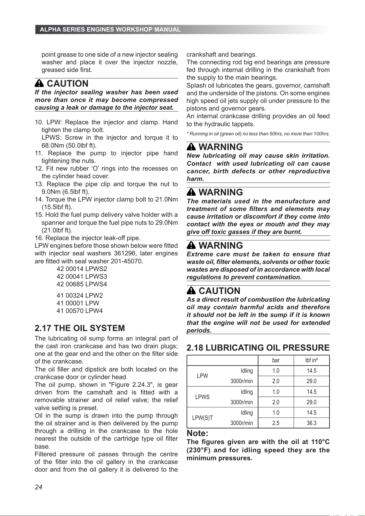
2.18 LUBRICATING OIL PRESSURE
bar lbf in²
LPW
Idling 1.0 14.5
3000r/min 2.0 29.0
LPWS
Idling 1.0 14.5
3000r/min 2.0 29.0
LPW(S)T
Idling 1.0 14.5
3000r/min 2.5 36.3
Note:
The gures given are with the oil at 110°C
(230°F) and for idling speed they are the
minimum pressures.
All manuals and user guides at all-guides.com
Page 25
ALPHA SERIES ENGINES WORKSHOP MANUAL
25
2.19 THE OIL DIPSTICK
Extreme care must be taken to ensure the correct
dipstick is returned to the engine.
Illustrations of the various dipsticks can be found in
the relevant Master Parts Manual.
2.20 OIL AND FILTER CHANGES
Before attempting to change the lubricating oil it is
essential to identify the type and build of engine and
ensure the new oil meets the correct specication
On engines built since 1 January 2005 (serial
number plate year code 05) lubricating oil lter 328-
21600 replaced 201-55370, 751-10620 and 751-
12870; refer to "2.22.1 Oil Filter Identication".
Note:
Continuous operation under heavy loads
in ambient temperatures above 35°C (95°F)
causes the oil to deteriorate faster.
To help assist engine running-in, all LPW, LPWS
and LPW(S)T4 engines are despatched with an
initial ll lubricating oil which must be changed with
the lter, at 100 hours and then as specied below.
Ambient
Temperature
Periods in Hours
LPW LPWT LPWS LPWST
Up to 35ºC 500 250 250 250
Above 35ºC 250 125 125 125
2.21 DRAINING THE OIL SUMP
Oil drain plugs are located on the oil lter side and
at the gear end of the crankcase.
If the engine has been run immediately before
draining the warm oil will drain quicker.
Before draining the oil sump read the precautions
on the previous page.
2.21.1 Draining the Oil Sump - Industrial
1. Run the engine to warm the oil.
2. Remove the oil ller cap.
3. Remove the oil sump drain plug and allow the oil
to run into a suitably sized container.
4. Clean the drain plug threads and coat them with
Hylomar PL32/M, Loctite 572 or Hylogrip 760.
5. Replace the plug and tighten it.
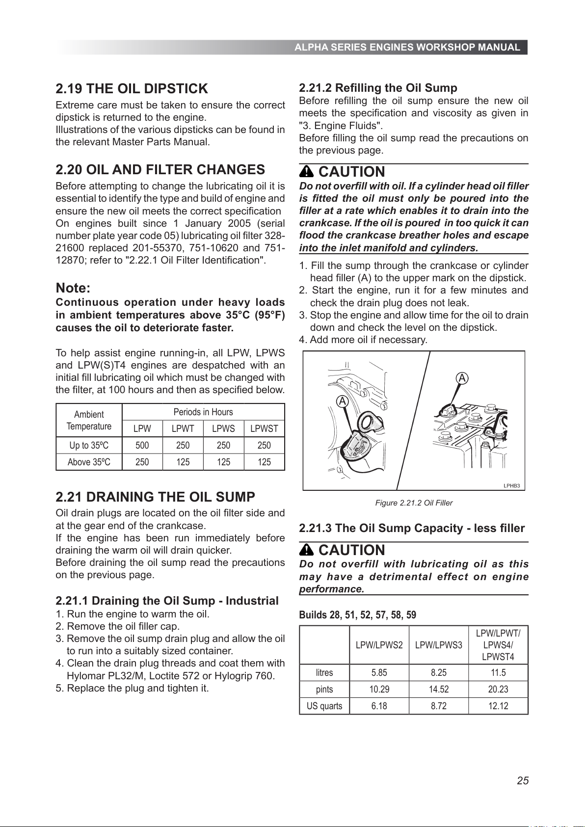
2.21.2 Relling the Oil Sump
Before relling the oil sump ensure the new oil
meets the specication and viscosity as given in
"3. Engine Fluids".
Before lling the oil sump read the precautions on
the previous page.
CAUTION
Do not overll with oil. If a cylinder head oil ller
is tted the oil must only be poured into the
ller at a rate which enables it to drain into the
crankcase. If the oil is poured in too quick it can
ood the crankcase breather holes and escape
into the inlet manifold and cylinders.
1. Fill the sump through the crankcase or cylinder
head ller (A) to the upper mark on the dipstick.
2. Start the engine, run it for a few minutes and
check the drain plug does not leak.
3. Stop the engine and allow time for the oil to drain
down and check the level on the dipstick.
4. Add more oil if necessary.
Figure 2.21.2 Oil Filler
2.21.3 The Oil Sump Capacity - less ller
CAUTION
Do not overfill with lubricating oil as this
may have a detr imenta l effe ct on engin e
performance.
Builds 28, 51, 52, 57, 58, 59
LPW/LPWS2 LPW/LPWS3
LPW/LPWT/
LPWS4/
LPWST4
litres 5.85 8.25 11.5
pints 10.29 14.52 20.23
US quarts 6.18 8.72 12.12
All manuals and user guides at all-guides.com
Page 26
ALPHA SERIES ENGINES WORKSHOP MANUAL
26
All builds except 28 ,51, 52, 57, 58, 59
LPW/LPWS2 LPW/LPWS3
LPW/LPWT/
LPWS4/
LPWST4
litres 3.00 3.75 5.50
pints 5.28 6.60 9.68
US quarts 3.17 3.96 5.81
2.21.4 Capacity Between Dipstick Marks
All builds except 28 ,51, 52, 57, 58, 59
LPW/LPWS2 LPW/LPWS23
LPW/LPWT/
LPWS4/
LPWST4
litres 0.9 0.95 1.2
pints 1.58 1.67 2.11
US quarts 0.95 1.00 1.27
Builds 28, 51, 52, 57, 58, 59
LPW/LPWS2 LPW/LPWS3
LPW/LPWT/
LPWS4/
LPWST4
litres 1.50 1.75 2.20
pints 2.64 3.08 3.87
US quarts 1.59 1.85 2.32
2.22 THE OIL FILTER
The standard full flow oil filter is a spin-on cartridge
type usually located on the crankcase door. In
some applications with limited space a remote filter
arrangement may be fitted.
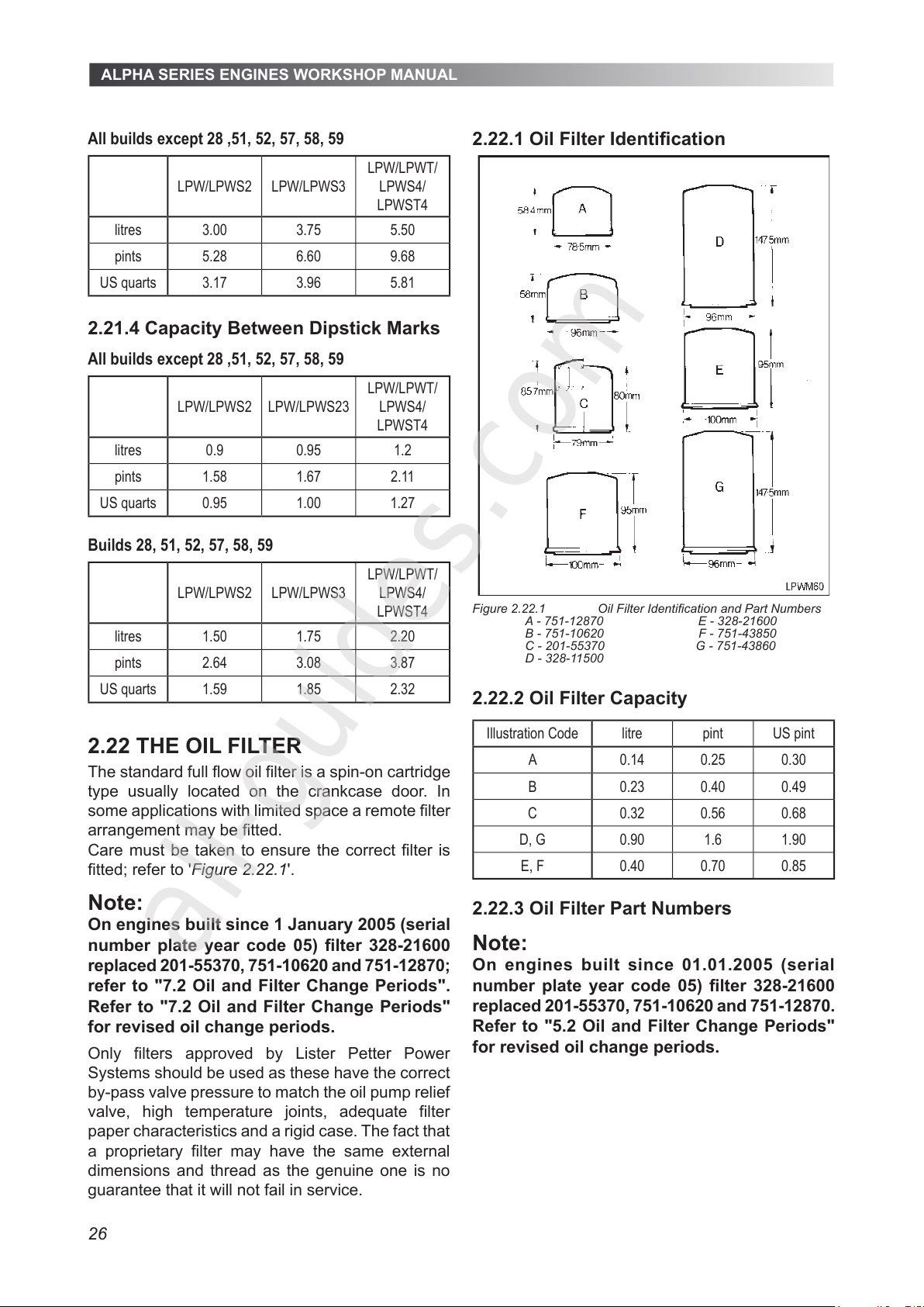
Care must be taken to ensure the correct filter is
fitted; refer to 'Figure 2.22.1'.
Note:
On engines built since 1 January 2005 (serial
number plate year code 05) filter 328-21600
replaced 201-55370, 751-10620 and 751-12870;
refer to "7.2 Oil and Filter Change Periods".
Refer to "7.2 Oil and Filter Change Periods"
for revised oil change periods.
2.22.1 Oil Filter Identification
Figure 2.22.1 Oil Filter Identification and Part Numbers
A - 751-12870 E - 328-21600
B - 751-10620 F - 751-43850
C - 201-55370 G - 751-43860
D - 328-11500
2.22.2 Oil Filter Capacity
Illustration Code litre pint US pint
A 0.14 0.25 0.30
B 0.23 0.40 0.49
C 0.32 0.56 0.68
D, G 0.90 1.6 1.90
E, F 0.40 0.70 0.85
2.22.3 Oil Filter Part Numbers
Note:
On engines built since 01.01.2005 (serial
number plate year code 05) filter 328-21600
replaced 201-55370, 751-10620 and 751-12870.
Refer to "5.2 Oil and Filter Change Periods"
for revised oil change periods.
Only filters approved by Lister Petter Power
Systems should be used as these have the correct
by-pass valve pressure to match the oil pump relief
valve, high temperature joints, adequate filter
paper characteristics and a rigid case. The fact that
a proprietary filter may have the same external
dimensions and thread as the genuine one is no
guarantee that it will not fail in service.
All manuals and user guides at all-guides.com
all-guides.com
Page 27
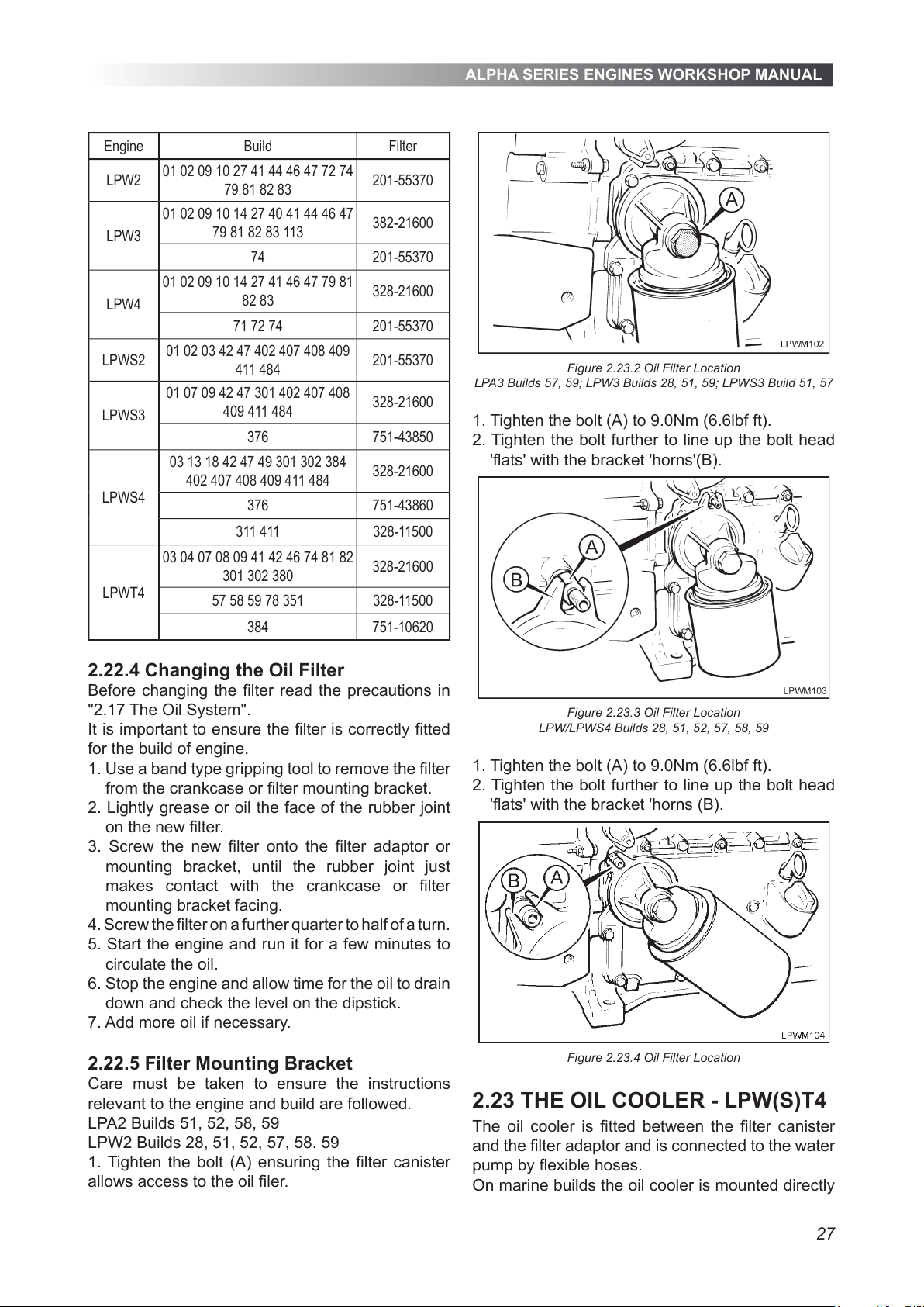
ALPHA SERIES ENGINES WORKSHOP MANUAL
27
Engine Build Filter
LPW2
01 02 09 10 27 41 44 46 47 72 74
79 81 82 83
201-55370
LPW3
01 02 09 10 14 27 40 41 44 46 47
79 81 82 83 113
382-21600
74 201-55370
LPW4
01 02 09 10 14 27 41 46 47 79 81
82 83
328-21600
71 72 74 201-55370
LPWS2
01 02 03 42 47 402 407 408 409
411 484
201-55370
LPWS3
01 07 09 42 47 301 402 407 408
409 411 484
328-21600
376 751-43850
LPWS4
03 13 18 42 47 49 301 302 384
402 407 408 409 411 484
328-21600
376 751-43860
311 411 328-11500
LPWT4
03 04 07 08 09 41 42 46 74 81 82
301 302 380
328-21600
57 58 59 78 351 328-11500
384 751-10620
2.22.4 Changing the Oil Filter
Before changing the lter read the precautions in
"2.17 The Oil System".
It is important to ensure the lter is correctly tted
for the build of engine.
1. Use a band type gripping tool to remove the lter
from the crankcase or lter mounting bracket.
2. Lightly grease or oil the face of the rubber joint
on the new lter.
3. Screw the new lter onto the lter adaptor or
mounting bracket, until the rubber joint just
makes contact with the crankcase or lter
mounting bracket facing.
4. Screw the lter on a further quarter to half of a turn.
5. Start the engine and run it for a few minutes to
circulate the oil.
6. Stop the engine and allow time for the oil to drain
down and check the level on the dipstick.
7. Add more oil if necessary.
2.22.5 Filter Mounting Bracket
Care must be taken to ensure the instructions
relevant to the engine and build are followed.
LPA2 Builds 51, 52, 58, 59
LPW2 Builds 28, 51, 52, 57, 58. 59
1. Tighten the bolt (A) ensuring the lter canister
allows access to the oil ler.
Figure 2.23.2 Oil Filter Location
LPA3 Builds 57, 59; LPW3 Builds 28, 51, 59; LPWS3 Build 51, 57
1. Tighten the bolt (A) to 9.0Nm (6.6lbf ft).
2. Tighten the bolt further to line up the bolt head
'ats' with the bracket 'horns'(B).
Figure 2.23.3 Oil Filter Location
LPW/LPWS4 Builds 28, 51, 52, 57, 58, 59
1. Tighten the bolt (A) to 9.0Nm (6.6lbf ft).
2. Tighten the bolt further to line up the bolt head
'ats' with the bracket 'horns (B).
Figure 2.23.4 Oil Filter Location
2.23 THE OIL COOLER - LPW(S)T4
The oil cooler is tted between the lter canister
and the lter adaptor and is connected to the water
pump by exible hoses.
On marine builds the oil cooler is mounted directly
All manuals and user guides at all-guides.com
Page 28
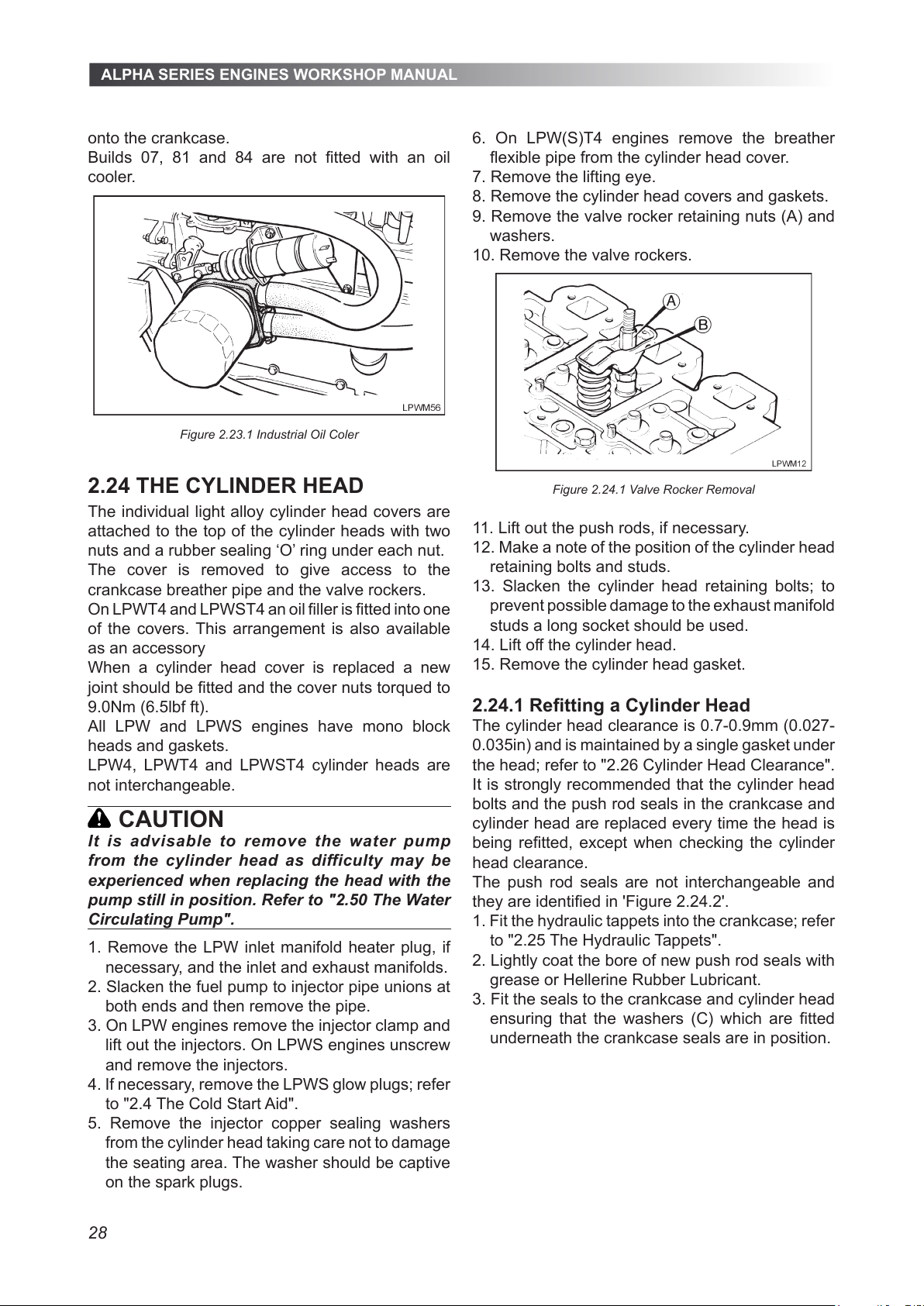
ALPHA SERIES ENGINES WORKSHOP MANUAL
28
onto the crankcase.
Builds 07, 81 and 84 are not tted with an oil
cooler.
Figure 2.23.1 Industrial Oil Coler
2.24 THE CYLINDER HEAD
The individual light alloy cylinder head covers are
attached to the top of the cylinder heads with two
nuts and a rubber sealing ‘O’ ring under each nut.
The cover is removed to give access to the
crankcase breather pipe and the valve rockers.
On LPWT4 and LPWST4 an oil ller is tted into one
of the covers. This arrangement is also available
as an accessory
When a cylinder head cover is replaced a new
joint should be tted and the cover nuts torqued to
9.0Nm (6.5lbf ft).
All LPW and LPWS engines have mono block
heads and gaskets.
LPW4, LPWT4 and LPWST4 cylinder heads are
not interchangeable.
CAUTION
It is advisable to remove the water pump
from the cylinder head as difficulty may be
experienced when replacing the head with the
pump still in position. Refer to "2.50 The Water
Circulating Pump".
1. Remove the LPW inlet manifold heater plug, if
necessary, and the inlet and exhaust manifolds.
2. Slacken the fuel pump to injector pipe unions at
both ends and then remove the pipe.
3. On LPW engines remove the injector clamp and
lift out the injectors. On LPWS engines unscrew
and remove the injectors.
4. If necessary, remove the LPWS glow plugs; refer
to "2.4 The Cold Start Aid".
5. Remove the injector copper sealing washers
from the cylinder head taking care not to damage
the seating area. The washer should be captive
on the spark plugs.
6. On LPW(S)T4 engines remove the breather
exible pipe from the cylinder head cover.
7. Remove the lifting eye.
8. Remove the cylinder head covers and gaskets.
9. Remove the valve rocker retaining nuts (A) and
washers.
10. Remove the valve rockers.
Figure 2.24.1 Valve Rocker Removal
11. Lift out the push rods, if necessary.
12. Make a note of the position of the cylinder head
retaining bolts and studs.
13. Slacken the cylinder head retaining bolts; to
prevent possible damage to the exhaust manifold
studs a long socket should be used.
14. Lift off the cylinder head.
15. Remove the cylinder head gasket.
2.24.1 Retting a Cylinder Head
The cylinder head clearance is 0.7-0.9mm (0.027-
0.035in) and is maintained by a single gasket under
the head; refer to "2.26 Cylinder Head Clearance".
It is strongly recommended that the cylinder head
bolts and the push rod seals in the crankcase and
cylinder head are replaced every time the head is
being retted, except when checking the cylinder
head clearance.
The push rod seals are not interchangeable and
they are identied in 'Figure 2.24.2'.
1. Fit the hydraulic tappets into the crankcase; refer
to "2.25 The Hydraulic Tappets".
2. Lightly coat the bore of new push rod seals with
grease or Hellerine Rubber Lubricant.
3. Fit the seals to the crankcase and cylinder head
ensuring that the washers (C) which are tted
underneath the crankcase seals are in position.
All manuals and user guides at all-guides.com
Page 29
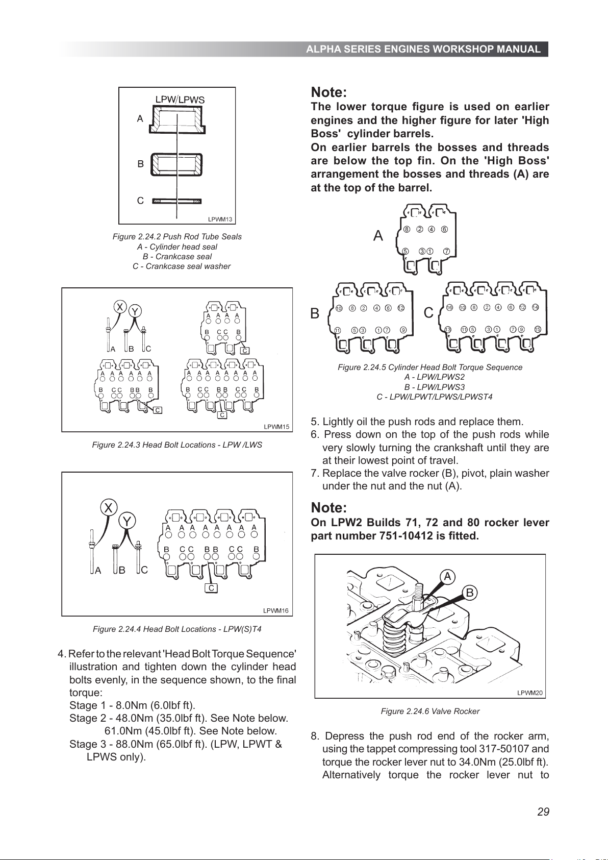
ALPHA SERIES ENGINES WORKSHOP MANUAL
29
Figure 2.24.2 Push Rod Tube Seals
A - Cylinder head seal
B - Crankcase seal
C - Crankcase seal washer
Figure 2.24.3 Head Bolt Locations - LPW /LWS
Figure 2.24.4 Head Bolt Locations - LPW(S)T4
4. Refer to the relevant 'Head Bolt Torque Sequence'
illustration and tighten down the cylinder head
bolts evenly, in the sequence shown, to the nal
torque:
Stage 1 - 8.0Nm (6.0lbf ft).
Stage 2 - 48.0Nm (35.0lbf ft). See Note below.
61.0Nm (45.0lbf ft). See Note below.
Stage 3 - 88.0Nm (65.0lbf ft). (LPW, LPWT &
LPWS only).
Note:
The lower torque gure is used on earlier
engines and the higher gure for later 'High
Boss' cylinder barrels.
On earlier barrels the bosses and threads
are below the top fin. On the 'High Boss'
arrangement the bosses and threads (A) are
at the top of the barrel.
Figure 2.24.5 Cylinder Head Bolt Torque Sequence
A - LPW/LPWS2
B - LPW/LPWS3
C - LPW/LPWT/LPWS/LPWST4
5. Lightly oil the push rods and replace them.
6. Press down on the top of the push rods while
very slowly turning the crankshaft until they are
at their lowest point of travel.
7. Replace the valve rocker (B), pivot, plain washer
under the nut and the nut (A).
Note:
On LPW2 Builds 71, 72 and 80 rocker lever
part number 751-10412 is tted.
Figure 2.24.6 Valve Rocker
8. Depress the push rod end of the rocker arm,
using the tappet compressing tool 317-50107 and
torque the rocker lever nut to 34.0Nm (25.0lbf ft).
Alternatively torque the rocker lever nut to
All manuals and user guides at all-guides.com
Page 30
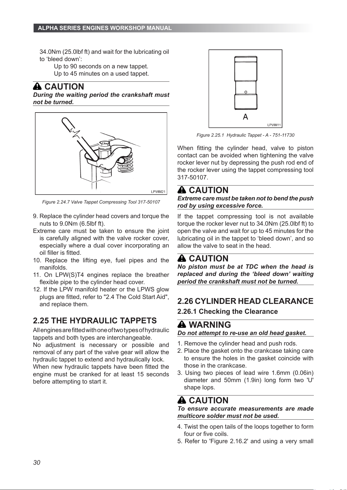
ALPHA SERIES ENGINES WORKSHOP MANUAL
30
34.0Nm (25.0lbf ft) and wait for the lubricating oil
to ‘bleed down’:
Up to 90 seconds on a new tappet.
Up to 45 minutes on a used tappet.
CAUTION
During the waiting period the crankshaft must
not be turned.
Figure 2.24.7 Valve Tappet Compressing Tool 317-50107
9. Replace the cylinder head covers and torque the
nuts to 9.0Nm (6.5lbf ft).
Extreme care must be taken to ensure the joint
is carefully aligned with the valve rocker cover,
especially where a dual cover incorporating an
oil ller is tted.
10. Replace the lifting eye, fuel pipes and the
manifolds.
11. On LPW(S)T4 engines replace the breather
exible pipe to the cylinder head cover.
12. If the LPW manifold heater or the LPWS glow
plugs are tted, refer to "2.4 The Cold Start Aid",
and replace them.
2.25 THE HYDRAULIC TAPPETS
All engines are tted with one of two types of hydraulic
tappets and both types are interchangeable.
No adjustment is necessary or possible and
removal of any part of the valve gear will allow the
hydraulic tappet to extend and hydraulically lock.
When new hydraulic tappets have been tted the
engine must be cranked for at least 15 seconds
before attempting to start it.
Figure 2.25.1 Hydraulic Tappet - A - 751-11730
When tting the cylinder head, valve to piston
contact can be avoided when tightening the valve
rocker lever nut by depressing the push rod end of
the rocker lever using the tappet compressing tool
317-50107.
CAUTION
Extreme care must be taken not to bend the push
rod by using excessive force.
If the tappet compressing tool is not available
torque the rocker lever nut to 34.0Nm (25.0lbf ft) to
open the valve and wait for up to 45 minutes for the
lubricating oil in the tappet to ‘bleed down’, and so
allow the valve to seat in the head.
CAUTION
No piston must be at TDC when the head is
replaced and during the ‘bleed down’ waiting
period the crankshaft must not be turned.
2.26 CYLINDER HEAD CLEARANCE
2.26.1 Checking the Clearance
WARNING
Do not attempt to re-use an old head gasket.
1. Remove the cylinder head and push rods.
2. Place the gasket onto the crankcase taking care
to ensure the holes in the gasket coincide with
those in the crankcase.
3. Using two pieces of lead wire 1.6mm (0.06in)
diameter and 50mm (1.9in) long form two 'U'
shape lops.
CAUTION
To ensure accurate measurements are made
multicore solder must not be used.
4. Twist the open tails of the loops together to form
four or ve coils.
5. Refer to 'Figure 2.16.2' and using a very small
All manuals and user guides at all-guides.com
Page 31
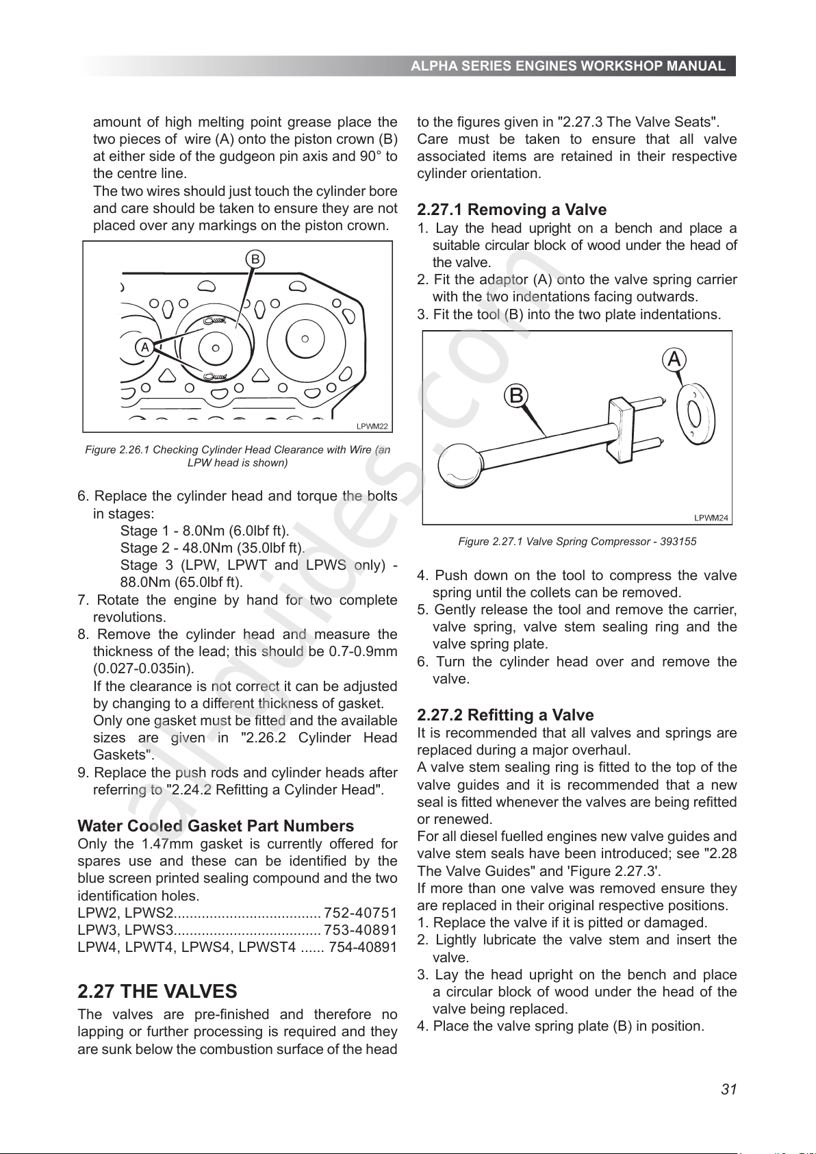
ALPHA SERIES ENGINES WORKSHOP MANUAL
31
amount of high melting point grease place the
two pieces of wire (A) onto the piston crown (B)
at either side of the gudgeon pin axis and 90° to
the centre line.
The two wires should just touch the cylinder bore
and care should be taken to ensure they are not
placed over any markings on the piston crown.
Figure 2.26.1 Checking Cylinder Head Clearance with Wire (an
LPW head is shown)
6. Replace the cylinder head and torque the bolts
in stages:
Stage 1 - 8.0Nm (6.0lbf ft).
Stage 2 - 48.0Nm (35.0lbf ft).
Stage 3 (LPW, LPWT and LPWS only) -
88.0Nm (65.0lbf ft).
7. Rotate the engine by hand for two complete
revolutions.
8. Remove the cylinder head and measure the
thickness of the lead; this should be 0.7-0.9mm
(0.027-0.035in).
If the clearance is not correct it can be adjusted
by changing to a different thickness of gasket.
Only one gasket must be tted and the available
sizes are given in "2.26.2 Cylinder Head
Gaskets".
9. Replace the push rods and cylinder heads after
referring to "2.24.2 Retting a Cylinder Head".
Water Cooled Gasket Part Numbers
Only the 1.47mm gasket is currently offered for
spares use and these can be identied by the
blue screen printed sealing compound and the two
identication holes.
LPW2, LPWS2..................................... 752-40751
LPW3, LPWS3..................................... 753-40891
LPW4, LPWT4, LPWS4, LPWST4 ...... 754-40891
2.27 THE VALVES
The valves are pre-nished and therefore no
lapping or further processing is required and they
are sunk below the combustion surface of the head
to the gures given in "2.27.3 The Valve Seats".
Care must be taken to ensure that all valve
associated items are retained in their respective
cylinder orientation.
2.27.1 Removing a Valve
1. Lay the head upright on a bench and place a
suitable circular block of wood under the head of
the valve.
2. Fit the adaptor (A) onto the valve spring carrier
with the two indentations facing outwards.
3. Fit the tool (B) into the two plate indentations.
Figure 2.27.1 Valve Spring Compressor - 393155
4. Push down on the tool to compress the valve
spring until the collets can be removed.
5. Gently release the tool and remove the carrier,
valve spring, valve stem sealing ring and the
valve spring plate.
6. Turn the cylinder head over and remove the
valve.
2.27.2 Retting a Valve
It is recommended that all valves and springs are
replaced during a major overhaul.
A valve stem sealing ring is tted to the top of the
valve guides and it is recommended that a new
seal is tted whenever the valves are being retted
or renewed.
For all diesel fuelled engines new valve guides and
valve stem seals have been introduced; see "2.28
The Valve Guides" and 'Figure 2.27.3'.
If more than one valve was removed ensure they
are replaced in their original respective positions.
1. Replace the valve if it is pitted or damaged.
2. Lightly lubricate the valve stem and insert the
valve.
3. Lay the head upright on the bench and place
a circular block of wood under the head of the
valve being replaced.
4. Place the valve spring plate (B) in position.
All manuals and user guides at all-guides.com
all-guides.com
Page 32
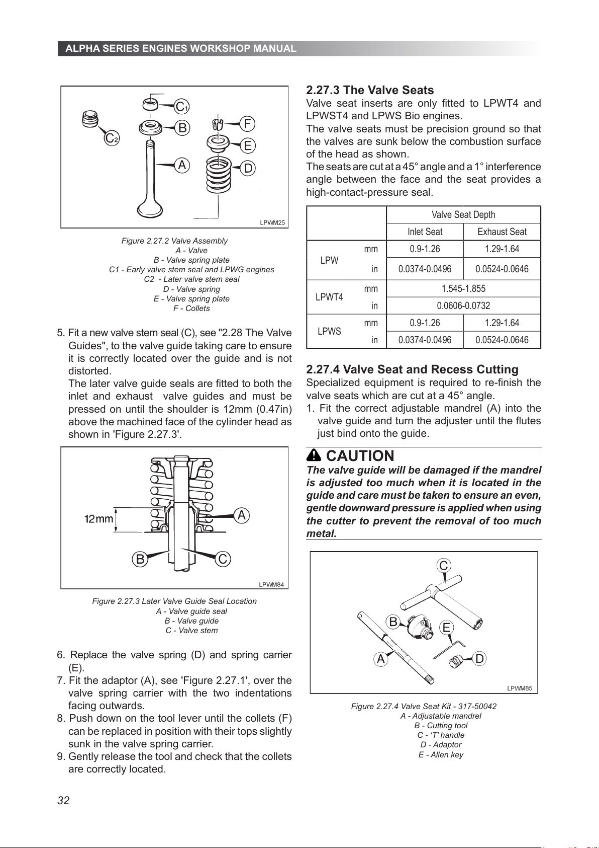
ALPHA SERIES ENGINES WORKSHOP MANUAL
32
Figure 2.27.2 Valve Assembly
A - Valve
B - Valve spring plate
C1 - Early valve stem seal and LPWG engines
C2 - Later valve stem seal
D - Valve spring
E - Valve spring plate
F - Collets
5. Fit a new valve stem seal (C), see "2.28 The Valve
Guides", to the valve guide taking care to ensure
it is correctly located over the guide and is not
distorted.
The later valve guide seals are tted to both the
inlet and exhaust valve guides and must be
pressed on until the shoulder is 12mm (0.47in)
above the machined face of the cylinder head as
shown in 'Figure 2.27.3'.
Figure 2.27.3 Later Valve Guide Seal Location
A - Valve guide seal
B - Valve guide
C - Valve stem
6. Replace the valve spring (D) and spring carrier
(E).
7. Fit the adaptor (A), see 'Figure 2.27.1', over the
valve spring carrier with the two indentations
facing outwards.
8. Push down on the tool lever until the collets (F)
can be replaced in position with their tops slightly
sunk in the valve spring carrier.
9. Gently release the tool and check that the collets
are correctly located.
2.27.3 The Valve Seats
Valve seat inserts are only tted to LPWT4 and
LPWST4 and LPWS Bio engines.
The valve seats must be precision ground so that
the valves are sunk below the combustion surface
of the head as shown.
The seats are cut at a 45° angle and a 1° interference
angle between the face and the seat provides a
high-contact-pressure seal.
Valve Seat Depth
Inlet Seat Exhaust Seat
LPW
mm 0.9-1.26 1.29-1.64
in 0.0374-0.0496 0.0524-0.0646
LPWT4
mm 1.545-1.855
in 0.0606-0.0732
LPWS
mm 0.9-1.26 1.29-1.64
in 0.0374-0.0496 0.0524-0.0646
2.27.4 Valve Seat and Recess Cutting
Specialized equipment is required to re-nish the
valve seats which are cut at a 45° angle.
1. Fit the correct adjustable mandrel (A) into the
valve guide and turn the adjuster until the utes
just bind onto the guide.
CAUTION
The valve guide will be damaged if the mandrel
is adjusted too much when it is located in the
guide and care must be taken to ensure an even,
gentle downward pressure is applied when using
the cutter to prevent the removal of too much
metal.
Figure 2.27.4 Valve Seat Kit - 317-50042
A - Adjustable mandrel
B - Cutting tool
C - ‘T’ handle
D - Adaptor
E - Allen key
All manuals and user guides at all-guides.com
Page 33
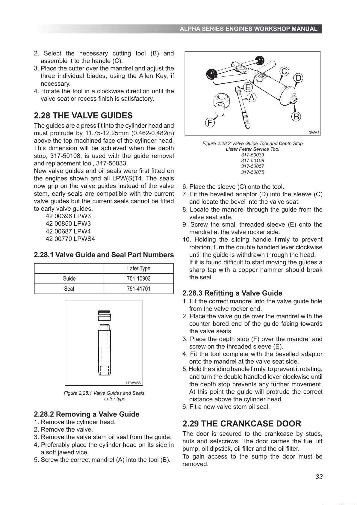
ALPHA SERIES ENGINES WORKSHOP MANUAL
33
2. Select the necessary cutting tool (B) and
assemble it to the handle (C).
3. Place the cutter over the mandrel and adjust the
three individual blades, using the Allen Key, if
necessary.
4. Rotate the tool in a clockwise direction until the
valve seat or recess nish is satisfactory.
2.28 THE VALVE GUIDES
The guides are a press t into the cylinder head and
must protrude by 11.75-12.25mm (0.462-0.482in)
above the top machined face of the cylinder head.
This dimension will be achieved when the depth
stop, 317-50108, is used with the guide removal
and replacement tool, 317-50033.
New valve guides and oil seals were rst tted on
the engines shown and all LPW(S)T4. The seals
now grip on the valve guides instead of the valve
stem, early seals are compatible with the current
valve guides but the current seals cannot be tted
to early valve guides.
42 00396 LPW3
42 00850 LPW3
42 00687 LPW4
42 00770 LPWS4
2.28.1 Valve Guide and Seal Part Numbers
Later Type
Guide 751-10903
Seal 751-41701
Figure 2.28.1 Valve Guides and Seals
Later type
2.28.2 Removing a Valve Guide
1. Remove the cylinder head.
2. Remove the valve.
3. Remove the valve stem oil seal from the guide.
4. Preferably place the cylinder head on its side in
a soft jawed vice.
5. Screw the correct mandrel (A) into the tool (B).
Figure 2.28.2 Valve Guide Tool and Depth Stop
Lister Petter Service Tool
317-50033
317-50108
317-50057
317-50075
6. Place the sleeve (C) onto the tool.
7. Fit the bevelled adaptor (D) into the sleeve (C)
and locate the bevel into the valve seat.
8. Locate the mandrel through the guide from the
valve seat side.
9. Screw the small threaded sleeve (E) onto the
mandrel at the valve rocker side.
10. Holding the sliding handle rmly to prevent
rotation, turn the double handled lever clockwise
until the guide is withdrawn through the head.
If it is found difcult to start moving the guides a
sharp tap with a copper hammer should break
the seal.
2.28.3 Retting a Valve Guide
1. Fit the correct mandrel into the valve guide hole
from the valve rocker end.
2. Place the valve guide over the mandrel with the
counter bored end of the guide facing towards
the valve seats.
3. Place the depth stop (F) over the mandrel and
screw on the threaded sleeve (E).
4. Fit the tool complete with the bevelled adaptor
onto the mandrel at the valve seat side.
5. Hold the sliding handle rmly, to prevent it rotating,
and turn the double handled lever clockwise until
the depth stop prevents any further movement.
At this point the guide will protrude the correct
distance above the cylinder head.
6. Fit a new valve stem oil seal.
2.29 THE CRANKCASE DOOR
The door is secured to the crankcase by studs,
nuts and setscrews. The door carries the fuel lift
pump, oil dipstick, oil ller and the oil lter.
To gain access to the sump the door must be
removed.
All manuals and user guides at all-guides.com
Page 34
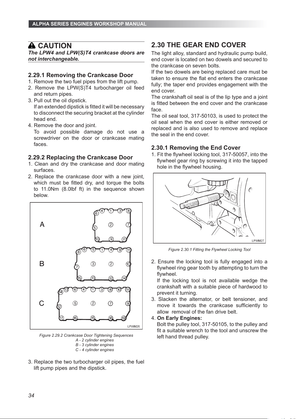
ALPHA SERIES ENGINES WORKSHOP MANUAL
34
CAUTION
The LPW4 and LPW(S)T4 crankcase doors are
not interchangeable.
2.29.1 Removing the Crankcase Door
1. Remove the two fuel pipes from the lift pump.
2. Remove the LPW(S)T4 turbocharger oil feed
and return pipes.
3. Pull out the oil dipstick.
If an extended dipstick is tted it will be necessary
to disconnect the securing bracket at the cylinder
head end.
4. Remove the door and joint.
To avoid possible damage do not use a
screwdriver on the door or crankcase mating
faces.
2.29.2 Replacing the Crankcase Door
1. Clean and dry the crankcase and door mating
surfaces.
2. Replace the crankcase door with a new joint,
which must be tted dry, and torque the bolts
to 11.0Nm (8.0lbf ft) in the sequence shown
below.
Figure 2.29.2 Crankcase Door Tightening Sequences
A - 2 cylinder engines
B - 3 cylinder engines
C - 4 cylinder engines
3. Replace the two turbocharger oil pipes, the fuel
lift pump pipes and the dipstick.
2.30 THE GEAR END COVER
The light alloy, standard and hydraulic pump build,
end cover is located on two dowels and secured to
the crankcase on seven bolts.
If the two dowels are being replaced care must be
taken to ensure the at end enters the crankcase
fully; the taper end provides engagement with the
end cover.
The crankshaft oil seal is of the lip type and a joint
is tted between the end cover and the crankcase
face.
The oil seal tool, 317-50103, is used to protect the
oil seal when the end cover is either removed or
replaced and is also used to remove and replace
the seal in the end cover.
2.30.1 Removing the End Cover
1. Fit the ywheel locking tool, 317-50057, into the
ywheel gear ring by screwing it into the tapped
hole in the ywheel housing.
Figure 2.30.1 Fitting the Flywheel Locking Tool
2. Ensure the locking tool is fully engaged into a
ywheel ring gear tooth by attempting to turn the
ywheel.
If the locking tool is not available wedge the
crankshaft with a suitable piece of hardwood to
prevent it turning.
3. Slacken the alternator, or belt tensioner, and
move it towards the crankcase sufciently to
allow removal of the fan drive belt.
4. On Early Engines:
Bolt the pulley tool, 317-50105, to the pulley and
t a suitable wrench to the tool and unscrew the
left hand thread pulley.
All manuals and user guides at all-guides.com
Page 35
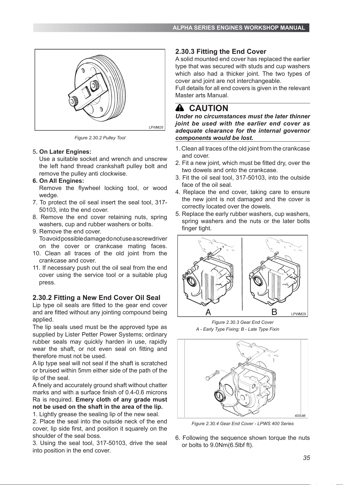
ALPHA SERIES ENGINES WORKSHOP MANUAL
35
Figure 2.30.2 Pulley Tool
5. On Later Engines:
Use a suitable socket and wrench and unscrew
the left hand thread crankshaft pulley bolt and
remove the pulley anti clockwise.
6. On All Engines:
Remove the flywheel locking tool, or wood
wedge.
7. To protect the oil seal insert the seal tool, 317-
50103, into the end cover.
8. Remove the end cover retaining nuts, spring
washers, cup and rubber washers or bolts.
9. Remove the end cover.
To avoid possible damage do not use a screwdriver
on the cover or crankcase mating faces.
10. Clean all traces of the old joint from the
crankcase and cover.
11. If necessary push out the oil seal from the end
cover using the service tool or a suitable plug
press.
2.30.2 Fitting a New End Cover Oil Seal
Lip type oil seals are fitted to the gear end cover
and are fitted without any jointing compound being
applied.
A lip type seal will not seal if the shaft is scratched
or bruised within 5mm either side of the path of the
lip of the seal.
A finely and accurately ground shaft without chatter
marks and with a surface finish of 0.4-0.6 microns
Ra is required. Emery cloth of any grade must
not be used on the shaft in the area of the lip.
1. Lightly grease the sealing lip of the new seal.
2. Place the seal into the outside neck of the end
cover, lip side first, and position it squarely on the
shoulder of the seal boss.
3. Using the seal tool, 317-50103, drive
the seal
into position in the end cover.
2.30.3 Fitting the End Cover
A solid mounted end cover has replaced the earlier
type that was secured with studs and cup washers
which also had a thicker joint. The two types of
cover and joint are not interchangeable.
Full details for all end covers is given in the relevant
Master arts Manual.
CAUTION
Under no circumstances must the later thinner
joint be used with the earlier end cover as
adequate clearance for the internal governor
components would be lost.
1. Clean all traces of the old joint from the crankcase
and cover.
2. Fit a new joint, which must be fitted dry, over the
two dowels and onto the crankcase.
3. Fit the oil seal tool, 317-50103, into the outside
face of the oil seal.
4. Replace the end cover, taking care to ensure
the new joint is not damaged and the cover is
correctly located over the dowels.
5. Replace the early rubber washers, cup washers,
spring washers and the nuts or the later bolts
finger tight.
Figure 2.30.3 Gear End Cover
A - Early Type Fixing; B - Late Type Fixin
Figure 2.30.4 Gear End Cover - LPWS 400 Series
6. Following the sequence shown torque the nuts
or bolts to 9.0Nm(6.5lbf ft).
The lip seals used must be the approved type as
supplied by Lister Petter Power Systems; ordinary
rubber seals may quickly harden in use, rapidly
wear the shaft, or not even seal on fitting and
therefore must not be used.
All manuals and user guides at all-guides.com
Page 36
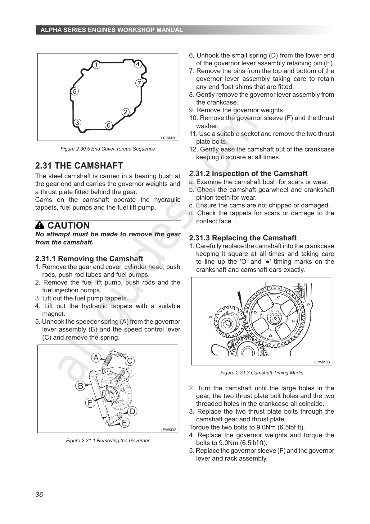
ALPHA SERIES ENGINES WORKSHOP MANUAL
36
Figure 2.30.5 End Cover Torque Sequence
2.31 THE CAMSHAFT
The steel camshaft is carried in a bearing bush at
the gear end and carries the governor weights and
a thrust plate tted behind the gear.
Cams on the camshaft operate the hydraulic
tappets, fuel pumps and the fuel lift pump.
CAUTION
No attempt must be made to remove the gear
from the camshaft.
2.31.1 Removing the Camshaft
1. Remove the gear end cover, cylinder head, push
rods, push rod tubes and fuel pumps.
2. Remove the fuel lift pump, push rods and the
fuel injection pumps.
3. Lift out the fuel pump tappets.
4. Lift out the hydraulic tappets with a suitable
magnet.
5. Unhook the speeder spring (A) from the governor
lever assembly (B) and the speed control lever
(C) and remove the spring.
Figure 2.31.1 Removing the Governor
6. Unhook the small spring (D) from the lower end
of the governor lever assembly retaining pin (E).
7. Remove the pins from the top and bottom of the
governor lever assembly taking care to retain
any end oat shims that are tted.
8. Gently remove the governor lever assembly from
the crankcase.
9. Remove the governor weights.
10. Remove the governor sleeve (F) and the thrust
washer.
11. Use a suitable socket and remove the two thrust
plate bolts.
12. Gently ease the camshaft out of the crankcase
keeping it square at all times.
2.31.2 Inspection of the Camshaft
a. Examine the camshaft bush for scars or wear.
b. Check the camshaft gearwheel and crankshaft
pinion teeth for wear.
c. Ensure the cams are not chipped or damaged.
d. Check the tappets for scars or damage to the
contact face.
2.31.3 Replacing the Camshaft
1. Carefully replace the camshaft into the crankcase
keeping it square at all times and taking care
to line up the 'O' and '●' timing marks on the
crankshaft and camshaft ears exactly.
Figure 2.31.3 Camshaft Timing Marks
2. Turn the camshaft until the large holes in the
gear, the two thrust plate bolt holes and the two
threaded holes in the crankcase all coincide.
3. Replace the two thrust plate bolts through the
camshaft gear and thrust plate.
Torque the two bolts to 9.0Nm (6.5lbf ft).
4. Replace the governor weights and torque the
bolts to 9.0Nm (6.5lbf ft).
5. Replace the governor sleeve (F) and the governor
lever and rack assembly.
All manuals and user guides at all-guides.com
all-guides.com
Page 37
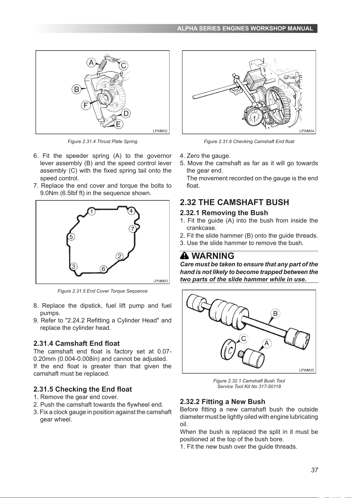
ALPHA SERIES ENGINES WORKSHOP MANUAL
37
Figure 2.31.4 Thrust Plate Spring
6. Fit the speeder spring (A) to the governor
lever assembly (B) and the speed control lever
assembly (C) with the xed spring tail onto the
speed control.
7. Replace the end cover and torque the bolts to
9.0Nm (6.5lbf ft) in the sequence shown.
Figure 2.31.5 End Cover Torque Sequence
8. Replace the dipstick, fuel lift pump and fuel
pumps.
9. Refer to "2.24.2 Retting a Cylinder Head" and
replace the cylinder head.
2.31.4 Camshaft End oat
The camshaft end oat is factory set at 0.07-
0.20mm (0.004-0.008in) and cannot be adjusted.
If the end oat is greater than that given the
camshaft must be replaced.
2.31.5 Checking the End oat
1. Remove the gear end cover.
2. Push the camshaft towards the ywheel end.
3. Fix a clock gauge in position against the camshaft
gear wheel.
Figure 2.31.6 Checking Camshaft End oat
4. Zero the gauge.
5. Move the camshaft as far as it will go towards
the gear end.
The movement recorded on the gauge is the end
oat.
2.32 THE CAMSHAFT BUSH
2.32.1 Removing the Bush
1. Fit the guide (A) into the bush from inside the
crankcase.
2. Fit the slide hammer (B) onto the guide threads.
3. Use the slide hammer to remove the bush.
WARNING
Care must be taken to ensure that any part of the
hand is not likely to become trapped between the
two parts of the slide hammer while in use.
Figure 2.32.1 Camshaft Bush Tool
Service Tool Kit No 317-50118
2.32.2 Fitting a New Bush
Before tting a new camshaft bush the outside
diameter must be lightly oiled with engine lubricating
oil.
When the bush is replaced the split in it must be
positioned at the top of the bush bore.
1. Fit the new bush over the guide threads.
All manuals and user guides at all-guides.com
Page 38
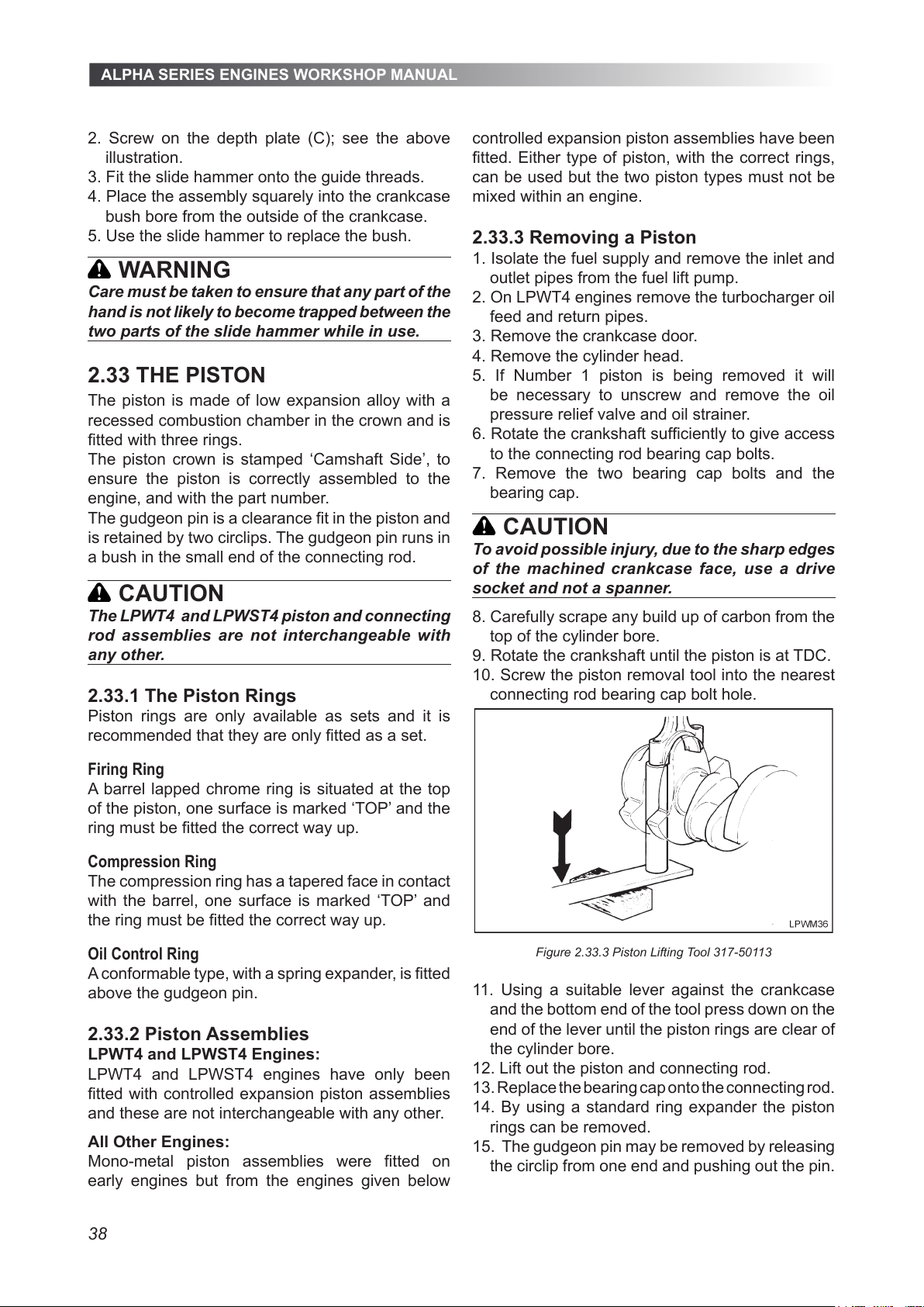
ALPHA SERIES ENGINES WORKSHOP MANUAL
38
2. Screw on the depth plate (C); see the above
illustration.
3. Fit the slide hammer onto the guide threads.
4. Place the assembly squarely into the crankcase
bush bore from the outside of the crankcase.
5. Use the slide hammer to replace the bush.
WARNING
Care must be taken to ensure that any part of the
hand is not likely to become trapped between the
two parts of the slide hammer while in use.
2.33 THE PISTON
The piston is made of low expansion alloy with a
recessed combustion chamber in the crown and is
tted with three rings.
The piston crown is stamped ‘Camshaft Side’, to
ensure the piston is correctly assembled to the
engine, and with the part number.
The gudgeon pin is a clearance t in the piston and
is retained by two circlips. The gudgeon pin runs in
a bush in the small end of the connecting rod.
CAUTION
The LPWT4 and LPWST4 piston and connecting
rod assemblies are not interchangeable with
any other.
2.33.1 The Piston Rings
Piston rings are only available as sets and it is
recommended that they are only tted as a set.
Firing Ring
A barrel lapped chrome ring is situated at the top
of the piston, one surface is marked ‘TOP’ and the
ring must be tted the correct way up.
Compression Ring
The compression ring has a tapered face in contact
with the barrel, one surface is marked ‘TOP’ and
the ring must be tted the correct way up.
Oil Control Ring
A conformable type, with a spring expander, is tted
above the gudgeon pin.
2.33.2 Piston Assemblies
LPWT4 and LPWST4 Engines:
LPWT4 and LPWST4 engines have only been
tted with controlled expansion piston assemblies
and these are not interchangeable with any other.
All Other Engines:
Mono-metal piston assemblies were tted on
early engines but from the engines given below
controlled expansion piston assemblies have been
tted. Either type of piston, with the correct rings,
can be used but the two piston types must not be
mixed within an engine.
2.33.3 Removing a Piston
1. Isolate the fuel supply and remove the inlet and
outlet pipes from the fuel lift pump.
2. On LPWT4 engines remove the turbocharger oil
feed and return pipes.
3. Remove the crankcase door.
4. Remove the cylinder head.
5. If Number 1 piston is being removed it will
be necessary to unscrew and remove the oil
pressure relief valve and oil strainer.
6. Rotate the crankshaft sufciently to give access
to the connecting rod bearing cap bolts.
7. Remove the two bearing cap bolts and the
bearing cap.
CAUTION
To avoid possible injury, due to the sharp edges
of the machined crankcase face, use a drive
socket and not a spanner.
8. Carefully scrape any build up of carbon from the
top of the cylinder bore.
9. Rotate the crankshaft until the piston is at TDC.
10. Screw the piston removal tool into the nearest
connecting rod bearing cap bolt hole.
Figure 2.33.3 Piston Lifting Tool 317-50113
11. Using a suitable lever against the crankcase
and the bottom end of the tool press down on the
end of the lever until the piston rings are clear of
the cylinder bore.
12. Lift out the piston and connecting rod.
13. Replace the bearing cap onto the connecting rod.
14. By using a standard ring expander the piston
rings can be removed.
15. The gudgeon pin may be removed by releasing
the circlip from one end and pushing out the pin.
All manuals and user guides at all-guides.com
Page 39
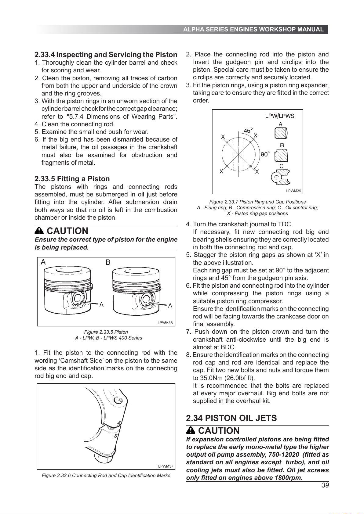
ALPHA SERIES ENGINES WORKSHOP MANUAL
39
2.33.4 Inspecting and Servicing the Piston
1. Thoroughly clean the cylinder barrel and check
for scoring and wear.
2. Clean the piston, removing all traces of carbon
from both the upper and underside of the crown
and the ring grooves.
3. With the piston rings in an unworn section of the
cylinder barrel check for the correct gap clearance;
refer to "5.7.4 Dimensions of Wearing Parts".
4. Clean the connecting rod.
5. Examine the small end bush for wear.
6. If the big end has been dismantled because of
metal failure, the oil passages in the crankshaft
must also be examined for obstruction and
fragments of metal.
2.33.5 Fitting a Piston
The pistons with rings and connecting rods
assembled, must be submerged in oil just before
tting into the cylinder. After submersion drain
both ways so that no oil is left in the combustion
chamber or inside the piston.
CAUTION
Ensure the correct type of piston for the engine
is being replaced.
Figure 2.33.5 Piston
A - LPW; B - LPWS 400 Series
1. Fit the piston to the connecting rod with the
wording ‘Camshaft Side’ on the piston to the same
side as the identication marks on the connecting
rod big end and cap.
Figure 2.33.6 Connecting Rod and Cap Identication Marks
2. Place the connecting rod into the piston and
Insert the gudgeon pin and circlips into the
piston. Special care must be taken to ensure the
circlips are correctly and securely located.
3. Fit the piston rings, using a piston ring expander,
taking care to ensure they are tted in the correct
order.
Figure 2.33.7 Piston Ring and Gap Positions
A - Firing ring; B - Compression ring; C - Oil control ring;
X - Piston ring gap positions
4. Turn the crankshaft journal to TDC.
If necessary, t new connecting rod big end
bearing shells ensuring they are correctly located
in both the connecting rod and cap.
5. Stagger the piston ring gaps as shown at ‘X’ in
the above illustration.
Each ring gap must be set at 90° to the adjacent
rings and 45° from the gudgeon pin axis.
6. Fit the piston and connecting rod into the cylinder
while compressing the piston rings using a
suitable piston ring compressor.
Ensure the identication marks on the connecting
rod will be facing towards the crankcase door on
nal assembly.
7. Push down on the piston crown and turn the
crankshaft anti-clockwise until the big end is
almost at BDC.
8. Ensure the identication marks on the connecting
rod cap and rod are identical and replace the
cap. Fit two new bolts and nuts and torque them
to 35.0Nm (26.0lbf ft).
It is recommended that the bolts are replaced
at every major overhaul. Big end bolts are not
supplied in the overhaul kit.
2.34 PISTON OIL JETS
CAUTION
If expansion controlled pistons are being tted
to replace the early mono-metal type the higher
output oil pump assembly, 750-12020 (tted as
standard on all engines except turbo), and oil
cooling jets must also be tted. Oil jet screws
only tted on engines above 1800rpm.
All manuals and user guides at all-guides.com
Page 40
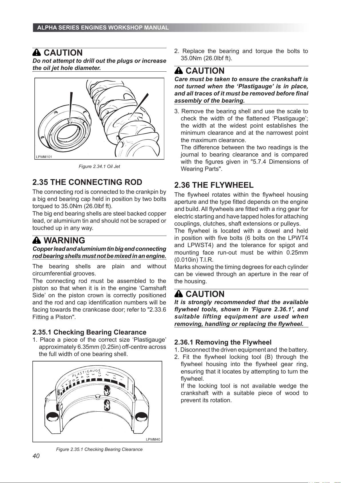
ALPHA SERIES ENGINES WORKSHOP MANUAL
40
CAUTION
Do not attempt to drill out the plugs or increase
the oil jet hole diameter.
Figure 2.34.1 Oil Jet
2.35 THE CONNECTING ROD
The connecting rod is connected to the crankpin by
a big end bearing cap held in position by two bolts
torqued to 35.0Nm (26.0lbf ft).
The big end bearing shells are steel backed copper
lead, or aluminium tin and should not be scraped or
touched up in any way.
WARNING
Copper lead and aluminium tin big end connecting
rod bearing shells must not be mixed in an engine.
The bearing shells are plain and without
circumferential grooves.
The connecting rod must be assembled to the
piston so that when it is in the engine ‘Camshaft
Side’ on the piston crown is correctly positioned
and the rod and cap identication numbers will be
facing towards the crankcase door; refer to "2.33.6
Fitting a Piston".
2.35.1 Checking Bearing Clearance
1. Place a piece of the correct size ‘Plastigauge’
approximately 6.35mm (0.25in) off-centre across
the full width of one bearing shell.
Figure 2.35.1 Checking Bearing Clearance
2. Replace the bearing and torque the bolts to
35.0Nm (26.0lbf ft).
CAUTION
Care must be taken to ensure the crankshaft is
not turned when the ‘Plastigauge’ is in place,
and all traces of it must be removed before nal
assembly of the bearing.
3. Remove the bearing shell and use the scale to
check the width of the attened ‘Plastigauge’;
the width at the widest point establishes the
minimum clearance and at the narrowest point
the maximum clearance.
The difference between the two readings is the
journal to bearing clearance and is compared
with the gures given in "5.7.4 Dimensions of
Wearing Parts".
2.36 THE FLYWHEEL
The ywheel rotates within the ywheel housing
aperture and the type tted depends on the engine
and build. All ywheels are tted with a ring gear for
electric starting and have tapped holes for attaching
couplings, clutches, shaft extensions or pulleys.
The ywheel is located with a dowel and held
in position with ve bolts (6 bolts on the LPWT4
and LPWST4) and the tolerance for spigot and
mounting face run-out must be within 0.25mm
(0.010in) T.I.R.
Marks showing the timing degrees for each cylinder
can be viewed through an aperture in the rear of
the housing.
CAUTION
It is strongly recommended that the available
ywheel tools, shown in 'Figure 2.36.1', and
suitable lif ting equipment are used when
removing, handling or replacing the ywheel.
2.36.1 Removing the Flywheel
1. Disconnect the driven equipment and the battery.
2. Fit the ywheel locking tool (B) through the
ywheel housing into the ywheel gear ring,
ensuring that it locates by attempting to turn the
ywheel.
If the locking tool is not available wedge the
crankshaft with a suitable piece of wood to
prevent its rotation.
All manuals and user guides at all-guides.com
Page 41
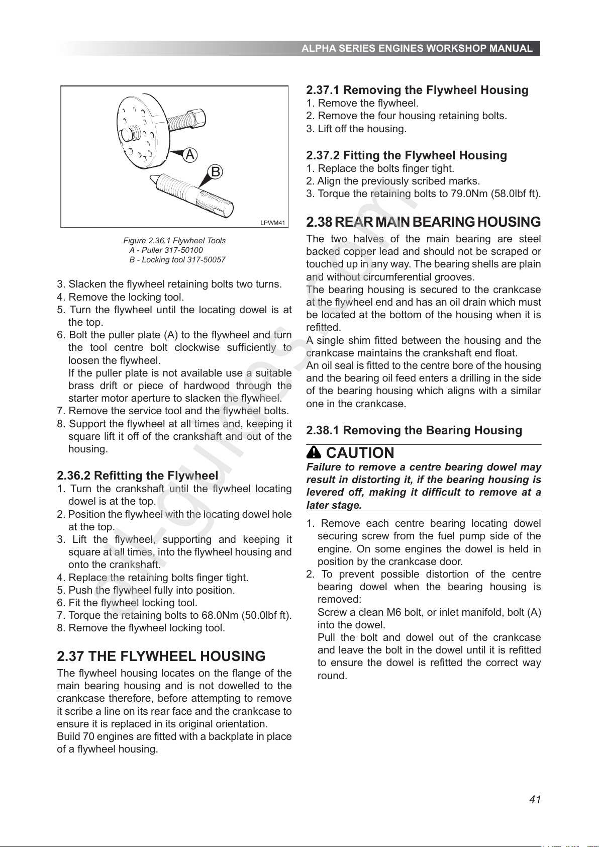
ALPHA SERIES ENGINES WORKSHOP MANUAL
41
Figure 2.36.1 Flywheel Tools
A - Puller 317-50100
B - Locking tool 317-50057
3. Slacken the ywheel retaining bolts two turns.
4. Remove the locking tool.
5. Turn the ywheel until the locating dowel is at
the top.
6. Bolt the puller plate (A) to the ywheel and turn
the tool centre bolt clockwise sufciently to
loosen the ywheel.
If the puller plate is not available use a suitable
brass drift or piece of hardwood through the
starter motor aperture to slacken the ywheel.
7. Remove the service tool and the ywheel bolts.
8. Support the ywheel at all times and, keeping it
square lift it off of the crankshaft and out of the
housing.
2.36.2 Retting the Flywheel
1. Turn the crankshaft until the ywheel locating
dowel is at the top.
2. Position the ywheel with the locating dowel hole
at the top.
3. Lift the ywheel, supporting and keeping it
square at all times, into the ywheel housing and
onto the crankshaft.
4. Replace the retaining bolts nger tight.
5. Push the ywheel fully into position.
6. Fit the ywheel locking tool.
7. Torque the retaining bolts to 68.0Nm (50.0lbf ft).
8. Remove the ywheel locking tool.
2.37 THE FLYWHEEL HOUSING
The ywheel housing locates on the ange of the
main bearing housing and is not dowelled to the
crankcase therefore, before attempting to remove
it scribe a line on its rear face and the crankcase to
ensure it is replaced in its original orientation.
Build 70 engines are tted with a backplate in place
of a ywheel housing.
2.37.1 Removing the Flywheel Housing
1. Remove the ywheel.
2. Remove the four housing retaining bolts.
3. Lift off the housing.
2.37.2 Fitting the Flywheel Housing
1. Replace the bolts nger tight.
2. Align the previously scribed marks.
3. Torque the retaining bolts to 79.0Nm (58.0lbf ft).
2.38 REAR MAIN BEARING HOUSING
The two halves of the main bearing are steel
backed copper lead and should not be scraped or
touched up in any way. The bearing shells are plain
and without circumferential grooves.
The bearing housing is secured to the crankcase
at the ywheel end and has an oil drain which must
be located at the bottom of the housing when it is
retted.
A single shim tted between the housing and the
crankcase maintains the crankshaft end oat.
An oil seal is tted to the centre bore of the housing
and the bearing oil feed enters a drilling in the side
of the bearing housing which aligns with a similar
one in the crankcase.
2.38.1 Removing the Bearing Housing
CAUTION
Failure to remove a centre bearing dowel may
result in distorting it, if the bearing housing is
levered off, making it difcult to remove at a
later stage.
1. Remove each centre bearing locating dowel
securing screw from the fuel pump side of the
engine. On some engines the dowel is held in
position by the crankcase door.
2. To prevent possible distortion of the centre
bearing dowel when the bearing housing is
removed:
Screw a clean M6 bolt, or inlet manifold, bolt (A)
into the dowel.
Pull the bolt and dowel out of the crankcase
and leave the bolt in the dowel until it is retted
to ensure the dowel is retted the correct way
round.
All manuals and user guides at all-guides.com
all-guides.com
Page 42
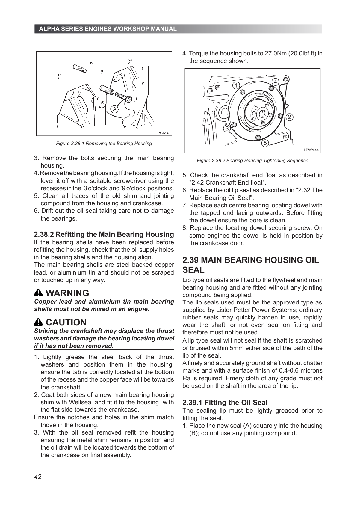
ALPHA SERIES ENGINES WORKSHOP MANUAL
42
Figure 2.38.1 Removing the Bearing Housing
3. Remove the bolts securing the main bearing
housing.
4. Remove the bearing housing. If the housing is tight,
lever it off with a suitable screwdriver using the
recesses in the ‘3 o'clock’ and ‘9 o'clock’ positions.
5. Clean all traces of the old shim and jointing
compound from the housing and crankcase.
6. Drift out the oil seal taking care not to damage
the bearings.
2.38.2 Refitting the Main Bearing Housing
If the bearing shells have been replaced before
refitting the housing, check that the oil supply holes
in the bearing shells and the housing align.
The main bearing shells are steel backed copper
lead, or aluminium tin and should not be scraped
or touched up in any way.
WARNING
Copper lead and aluminium tin main bearing
shells must not be mixed in an engine.
CAUTION
Striking the crankshaft may displace the thrust
washers and damage the bearing locating dowel
if it has not been removed.
1. Lightly grease the steel back of the thrust
washers and position them in the housing;
ensure the tab is correctly located at the bottom
of the recess and the copper face will be towards
the crankshaft.
2. Coat both sides of a new main bearing housing
shim with Wellseal and fit it to the housing with
the flat side towards the crankcase.
Ensure the notches and holes in the shim match
those in the housing.
3. With the oil seal removed refit the housing
ensuring the metal shim remains in position and
the oil drain will be located towards the bottom of
the crankcase on final assembly.
4. Torque the housing bolts to 27.0Nm (20.0lbf ft) in
the sequence shown.
Figure 2.38.2 Bearing Housing Tightening Sequence
5. Check the crankshaft end float as described in
"2.42 Crankshaft End float".
6. Replace the oil lip seal as described in "2.32 The
Main Bearing Oil Seal".
7. Replace each centre bearing locating dowel with
the tapped end facing outwards. Before fitting
the dowel ensure the bore is clean.
8. Replace the locating dowel securing screw. On
some engines the dowel is held in position by
the crankcase door.
2.39 MAIN BEARING HOUSING OIL
SEAL
Lip type oil seals are fitted to the flywheel end main
bearing housing and are fitted without any jointing
compound being applied.
A lip type seal will not seal if the shaft is scratched
or bruised within 5mm either side of the path of the
lip of the seal.
A finely and accurately ground shaft without chatter
marks and with a surface finish of 0.4-0.6 microns
Ra is required. Emery cloth of any grade must not
be used on the shaft in the area of the lip.
2.39.1 Fitting the Oil Seal
The sealing lip must be lightly greased prior to
fitting the seal.
1. Place the new seal (A) squarely into the housing
(B); do not use any jointing compound.
The lip seals used must be the approved type as
supplied by Lister Petter Power Systems; ordinary
rubber seals may quickly harden in use, rapidly
wear the shaft, or not even seal on fitting and
therefore must not be used.
All manuals and user guides at all-guides.com
Page 43
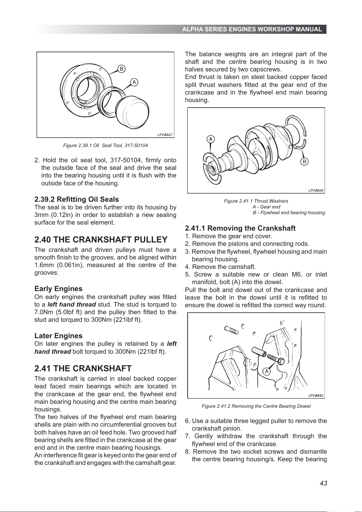
ALPHA SERIES ENGINES WORKSHOP MANUAL
43
Figure 2.39.1 Oil Seal Tool, 317-50104
2. Hold the oil seal tool, 317-50104, rmly onto
the outside face of the seal and drive the seal
into the bearing housing until it is ush with the
outside face of the housing.
2.39.2 Retting Oil Seals
The seal is to be driven further into its housing by
3mm (0.12in) in order to establish a new sealing
surface for the seal element.
2.40 THE CRANKSHAFT PULLEY
The crankshaft and driven pulleys must have a
smooth nish to the grooves, and be aligned within
1.6mm (0.061in), measured at the centre of the
grooves.
Early Engines
On early engines the crankshaft pulley was tted
to a left hand thread stud. The stud is torqued to
7.0Nm (5.0lbf ft) and the pulley then tted to the
stud and torqued to 300Nm (221lbf ft).
Later Engines
On later engines the pulley is retained by a left
hand thread bolt torqued to 300Nm (221lbf ft).
2.41 THE CRANKSHAFT
The crankshaft is carried in steel backed copper
lead faced main bearings which are located in
the crankcase at the gear end, the ywheel end
main bearing housing and the centre main bearing
housings.
The two halves of the ywheel end main bearing
shells are plain with no circumferential grooves but
both halves have an oil feed hole. Two grooved half
bearing shells are tted in the crankcase at the gear
end and in the centre main bearing housings.
An interference t gear is keyed onto the gear end of
the crankshaft and engages with the camshaft gear.
The balance weights are an integral part of the
shaft and the centre bearing housing is in two
halves secured by two capscrews.
End thrust is taken on steel backed copper faced
split thrust washers tted at the gear end of the
crankcase and in the ywheel end main bearing
housing.
Figure 2.41.1 Thrust Washers
A - Gear end
B - Flywheel end bearing housing
2.41.1 Removing the Crankshaft
1. Remove the gear end cover.
2. Remove the pistons and connecting rods.
3. Remove the ywheel, ywheel housing and main
bearing housing.
4. Remove the camshaft.
5. Screw a suitable new or clean M6, or inlet
manifold, bolt (A) into the dowel.
Pull the bolt and dowel out of the crankcase and
leave the bolt in the dowel until it is retted to
ensure the dowel is retted the correct way round.
Figure 2.41.2 Removing the Centre Bearing Dowel
6. Use a suitable three legged puller to remove the
crankshaft pinion.
7. Gently withdraw the crankshaft through the
ywheel end of the crankcase.
8. Remove the two socket screws and dismantle
the centre bearing housing/s. Keep the bearing
All manuals and user guides at all-guides.com
Page 44
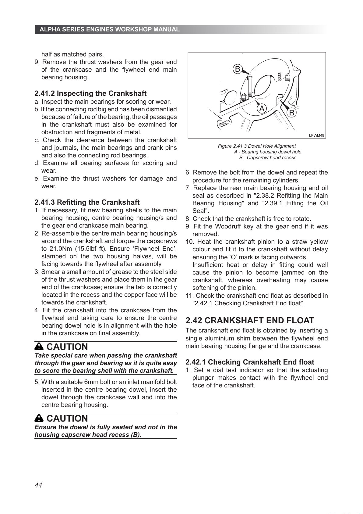
ALPHA SERIES ENGINES WORKSHOP MANUAL
44
half as matched pairs.
9. Remove the thrust washers from the gear end
of the crankcase and the ywheel end main
bearing housing.
2.41.2 Inspecting the Crankshaft
a. Inspect the main bearings for scoring or wear.
b. If the connecting rod big end has been dismantled
because of failure of the bearing, the oil passages
in the crankshaft must also be examined for
obstruction and fragments of metal.
c. Check the clearance between the crankshaft
and journals, the main bearings and crank pins
and also the connecting rod bearings.
d. Examine all bearing surfaces for scoring and
wear.
e. Examine the thrust washers for damage and
wear.
2.41.3 Retting the Crankshaft
1. If necessary, t new bearing shells to the main
bearing housing, centre bearing housing/s and
the gear end crankcase main bearing.
2. Re-assemble the centre main bearing housing/s
around the crankshaft and torque the capscrews
to 21.0Nm (15.5lbf ft). Ensure ‘Flywheel End’,
stamped on the two housing halves, will be
facing towards the ywheel after assembly.
3. Smear a small amount of grease to the steel side
of the thrust washers and place them in the gear
end of the crankcase; ensure the tab is correctly
located in the recess and the copper face will be
towards the crankshaft.
4. Fit the crankshaft into the crankcase from the
ywheel end taking care to ensure the centre
bearing dowel hole is in alignment with the hole
in the crankcase on nal assembly.
CAUTION
Take special care when passing the crankshaft
through the gear end bearing as it is quite easy
to score the bearing shell with the crankshaft.
5. With a suitable 6mm bolt or an inlet manifold bolt
inserted in the centre bearing dowel, insert the
dowel through the crankcase wall and into the
centre bearing housing.
CAUTION
Ensure the dowel is fully seated and not in the
housing capscrew head recess (B).
Figure 2.41.3 Dowel Hole Alignment
A - Bearing housing dowel hole
B - Capscrew head recess
6. Remove the bolt from the dowel and repeat the
procedure for the remaining cylinders.
7. Replace the rear main bearing housing and oil
seal as described in "2.38.2 Retting the Main
Bearing Housing" and "2.39.1 Fitting the Oil
Seal".
8. Check that the crankshaft is free to rotate.
9. Fit the Woodruff key at the gear end if it was
removed.
10. Heat the crankshaft pinion to a straw yellow
colour and t it to the crankshaft without delay
ensuring the ‘O’ mark is facing outwards.
Insufcient heat or delay in tting could well
cause the pinion to become jammed on the
crankshaft, whereas overheating may cause
softening of the pinion.
11. Check the crankshaft end oat as described in
"2.42.1 Checking Crankshaft End oat".
2.42 CRANKSHAFT END FLOAT
The crankshaft end oat is obtained by inserting a
single aluminium shim between the ywheel end
main bearing housing ange and the crankcase.
2.42.1 Checking Crankshaft End oat
1. Set a dial test indicator so that the actuating
plunger makes contact with the ywheel end
face of the crankshaft.
All manuals and user guides at all-guides.com
Page 45
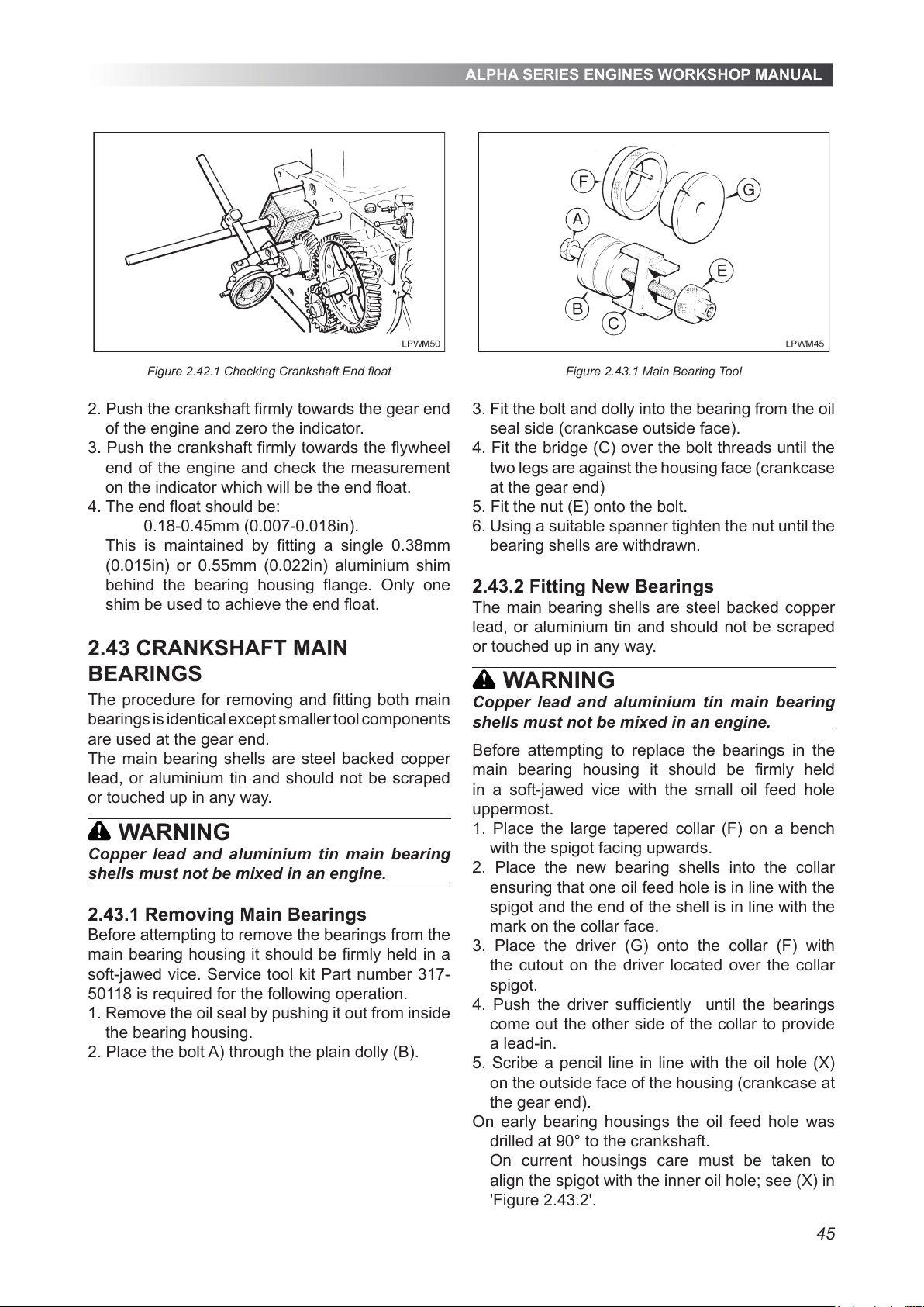
ALPHA SERIES ENGINES WORKSHOP MANUAL
45
Figure 2.42.1 Checking Crankshaft End oat
2. Push the crankshaft rmly towards the gear end
of the engine and zero the indicator.
3. Push the crankshaft rmly towards the ywheel
end of the engine and check the measurement
on the indicator which will be the end oat.
4. The end oat should be:
0.18-0.45mm (0.007-0.018in).
This is maintained by tting a single 0.38mm
(0.015in) or 0.55mm (0.022in) aluminium shim
behind the bearing housing ange. Only one
shim be used to achieve the end oat.
2.43 CRANKSHAFT MAIN
BEARINGS
The procedure for removing and tting both main
bearings is identical except smaller tool components
are used at the gear end.
The main bearing shells are steel backed copper
lead, or aluminium tin and should not be scraped
or touched up in any way.
WARNING
Copper lead and aluminium tin main bearing
shells must not be mixed in an engine.
2.43.1 Removing Main Bearings
Before attempting to remove the bearings from the
main bearing housing it should be rmly held in a
soft-jawed vice. Service tool kit Part number 317-
50118 is required for the following operation.
1. Remove the oil seal by pushing it out from inside
the bearing housing.
2. Place the bolt A) through the plain dolly (B).
Figure 2.43.1 Main Bearing Tool
3. Fit the bolt and dolly into the bearing from the oil
seal side (crankcase outside face).
4. Fit the bridge (C) over the bolt threads until the
two legs are against the housing face (crankcase
at the gear end)
5. Fit the nut (E) onto the bolt.
6. Using a suitable spanner tighten the nut until the
bearing shells are withdrawn.
2.43.2 Fitting New Bearings
The main bearing shells are steel backed copper
lead, or aluminium tin and should not be scraped
or touched up in any way.
WARNING
Copper lead and aluminium tin main bearing
shells must not be mixed in an engine.
Before attempting to replace the bearings in the
main bearing housing it should be rmly held
in a soft-jawed vice with the small oil feed hole
uppermost.
1. Place the large tapered collar (F) on a bench
with the spigot facing upwards.
2. Place the new bearing shells into the collar
ensuring that one oil feed hole is in line with the
spigot and the end of the shell is in line with the
mark on the collar face.
3. Place the driver (G) onto the collar (F) with
the cutout on the driver located over the collar
spigot.
4. Push the driver sufciently until the bearings
come out the other side of the collar to provide
a lead-in.
5. Scribe a pencil line in line with the oil hole (X)
on the outside face of the housing (crankcase at
the gear end).
On early bearing housings the oil feed hole was
drilled at 90° to the crankshaft.
On current housings care must be taken to
align the spigot with the inner oil hole; see (X) in
'Figure 2.43.2'.
All manuals and user guides at all-guides.com
Page 46
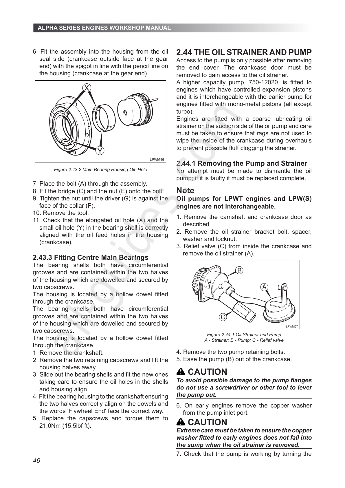
ALPHA SERIES ENGINES WORKSHOP MANUAL
46
6. Fit the assembly into the housing from the oil
seal side (crankcase outside face at the gear
end) with the spigot in line with the pencil line on
the housing (crankcase at the gear end).
Figure 2.43.2 Main Bearing Housing Oil Hole
7. Place the bolt (A) through the assembly.
8. Fit the bridge (C) and the nut (E) onto the bolt.
9. Tighten the nut until the driver (G) is against the
face of the collar (F).
10. Remove the tool.
11. Check that the elongated oil hole (X) and the
small oil hole (Y) in the bearing shell is correctly
aligned with the oil feed holes in the housing
(crankcase).
2.43.3 Fitting Centre Main Bearings
The bearing shells both have circumferential
grooves and are contained within the two halves
of the housing which are dowelled and secured by
two capscrews.
The housing is located by a hollow dowel tted
through the crankcase.
The bearing shells both have circumferential
grooves and are contained within the two halves
of the housing which are dowelled and secured by
two capscrews.
The housing is located by a hollow dowel tted
through the crankcase.
1. Remove the crankshaft.
2. Remove the two retaining capscrews and lift the
housing halves away.
3. Slide out the bearing shells and t the new ones
taking care to ensure the oil holes in the shells
and housing align.
4. Fit the bearing housing to the crankshaft ensuring
the two halves correctly align on the dowels and
the words 'Flywheel End' face the correct way.
5. Replace the capscrews and torque them to
21.0Nm (15.5lbf ft).
2.44 THE OIL STRAINER AND PUMP
Access to the pump is only possible after removing
the end cover. The crankcase door must be
removed to gain access to the oil strainer.
A higher capacity pump, 750-12020, is tted to
engines which have controlled expansion pistons
and it is interchangeable with the earlier pump for
engines tted with mono-metal pistons (all except
turbo).
Engines are tted with a coarse lubricating oil
strainer on the suction side of the oil pump and care
must be taken to ensure that rags are not used to
wipe the inside of the crankcase during overhauls
to prevent possible uff clogging the strainer.
2.44.1 Removing the Pump and Strainer
No attempt must be made to dismantle the oil
pump; if it is faulty it must be replaced complete.
Note
Oil pumps for LPWT engines and LPW(S)
engines are not interchangeable.
1. Remove the camshaft and crankcase door as
described.
2. Remove the oil strainer bracket bolt, spacer,
washer and locknut.
3. Relief valve (C) from inside the crankcase and
remove the oil strainer (A).
Figure 2.44.1 Oil Strainer and Pump
A - Strainer; B - Pump; C - Relief valve
4. Remove the two pump retaining bolts.
5. Ease the pump (B) out of the crankcase.
CAUTION
To avoid possible damage to the pump anges
do not use a screwdriver or other tool to lever
the pump out.
6. On early engines remove the copper washer
from the pump inlet port.
CAUTION
Extreme care must be taken to ensure the copper
washer tted to early engines does not fall into
the sump when the oil strainer is removed.
7. Check that the pump is working by turning the
All manuals and user guides at all-guides.com
all-guides.com
Page 47
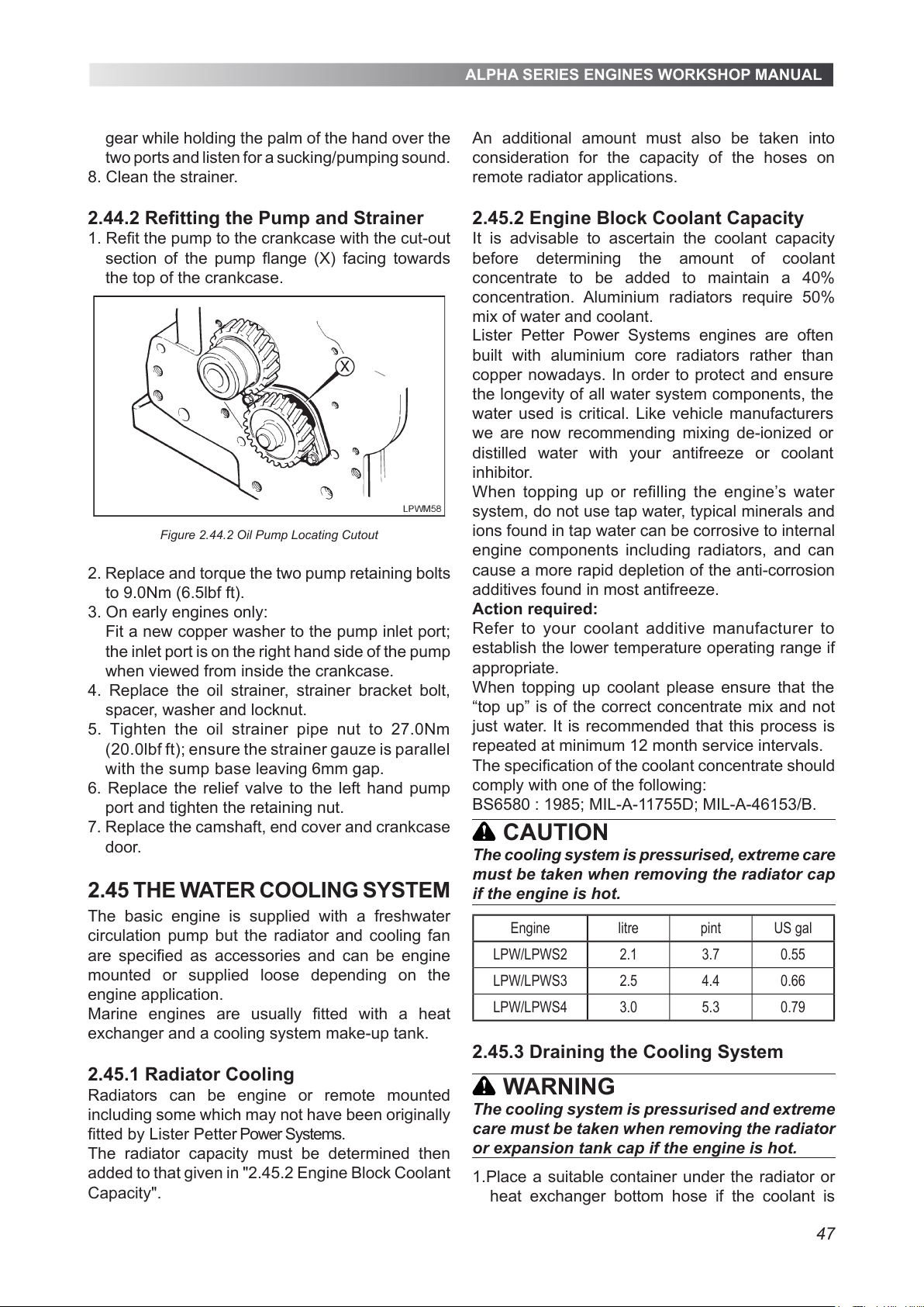
ALPHA SERIES ENGINES WORKSHOP MANUAL
47
gear while holding the palm of the hand over the
two ports and listen for a sucking/pumping sound.
8. Clean the strainer.
2.44.2 Refitting the Pump and Strainer
1. Refit the pump to the crankcase with the cut-out
section of the pump flange (X) facing towards
the top of the crankcase.
Figure 2.44.2 Oil Pump Locating Cutout
2. Replace and torque the two pump retaining bolts
to 9.0Nm (6.5lbf ft).
3. On early engines only:
Fit a new copper washer to the pump inlet port;
the inlet port is on the right hand side of the pump
when viewed from inside the crankcase.
4. Replace the oil strainer, strainer bracket bolt,
spacer, washer and locknut.
5. Tighten the oil strainer pipe nut to 27.0Nm
(20.0lbf ft); ensure the strainer gauze is parallel
with the sump base leaving 6mm gap.
6. Replace the relief valve to the left hand pump
port and tighten the retaining nut.
7. Replace the camshaft, end cover and crankcase
door.
2.45 THE WATER COOLING SYSTEM
The basic engine is supplied with a freshwater
circulation pump but the radiator and cooling fan
are specified as accessories and can be engine
mounted or supplied loose depending on the
engine application.
Marine engines are usually fitted with a heat
exchanger and a cooling system make-up tank.
2.45.1 Radiator Cooling
Radiators can be engine or remote mounted
including some which may not have been originally
fitted by Lister Petter Power Systems.
The radiator capacity must be determined then
added to that given in "2.45.2 Engine Block Coolant
Capacity".
An additional amount must also be taken into
consideration for the capacity of the hoses on
remote radiator applications.
2.45.2 Engine Block Coolant Capacity
It is advisable to ascertain the coolant capacity
before determining the amount of coolant
concentrate to be added to maintain a 40%
concentration. Aluminium radiators require 50%
mix of water and coolant.
When topping up or refilling the engine’s water
system, do not use tap water, typical minerals and
ions found in tap water can be corrosive to internal
engine components including radiators, and can
cause a more rapid depletion of the anti-corrosion
additives found in most antifreeze.
Action required:
Refer to your coolant additive manufacturer to
establish the lower temperature operating range if
appropriate.
When topping up coolant please ensure that the
“top up” is of the correct concentrate mix and not
just water. It is recommended that this process is
repeated at minimum 12 month service intervals.
The specification of the coolant concentrate should
comply with one of the following:
BS6580 : 1985; MIL-A-11755D; MIL-A-46153/B.
CAUTION
The cooling system is pressurised, extreme care
must be taken when removing the radiator cap
if the engine is hot.
Engine litre pint US gal
LPW/LPWS2 2.1 3.7 0.55
LPW/LPWS3 2.5 4.4 0.66
LPW/LPWS4 3.0 5.3 0.79
2.45.3 Draining the Cooling System
WARNING
The cooling system is pressurised and extreme
care must be taken when removing the radiator
or expansion tank cap if the engine is hot.
1.Place a suitable container under the radiator or
heat exchanger bottom hose if the coolant is
Lister Petter Power Systems engines are often
built with aluminium core radiators rather than
copper nowadays. In order to protect and ensure
the longevity of all water system components, the
water used is critical. Like vehicle manufacturers
we are now recommending mixing de-ionized or
distilled water with your antifreeze or coolant
inhibitor.
All manuals and user guides at all-guides.com
Page 48
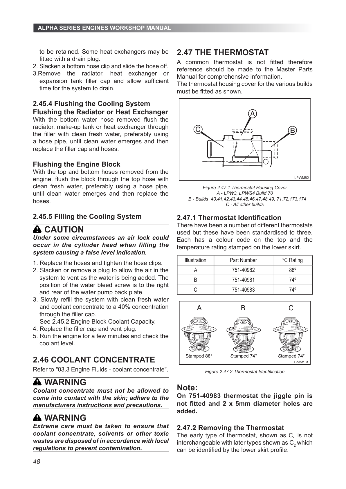
ALPHA SERIES ENGINES WORKSHOP MANUAL
48
to be retained. Some heat exchangers may be
tted with a drain plug.
2. Slacken a bottom hose clip and slide the hose off.
3.Remove the radiator, heat exchanger or
expansion tank ller cap and allow sufcient
time for the system to drain.
2.45.4 Flushing the Cooling System
Flushing the Radiator or Heat Exchanger
With the bottom water hose removed ush the
radiator, make-up tank or heat exchanger through
the ller with clean fresh water, preferably using
a hose pipe, until clean water emerges and then
replace the ller cap and hoses.
Flushing the Engine Block
With the top and bottom hoses removed from the
engine, ush the block through the top hose with
clean fresh water, preferably using a hose pipe,
until clean water emerges and then replace the
hoses.
2.45.5 Filling the Cooling System
CAUTION
Under some circumstances an air lock could
occur in the cylinder head when filling the
system causing a false level indication.
1. Replace the hoses and tighten the hose clips.
2. Slacken or remove a plug to allow the air in the
system to vent as the water is being added. The
position of the water bleed screw is to the right
and rear of the water pump back plate.
3. Slowly rell the system with clean fresh water
and coolant concentrate to a 40% concentration
through the ller cap.
See 2.45.2 Engine Block Coolant Capacity.
4. Replace the ller cap and vent plug.
5. Run the engine for a few minutes and check the
coolant level.
2.46 COOLANT CONCENTRATE
Refer to "03.3 Engine Fluids - coolant concentrate".
WARNING
Coolant concentrate must not be allowed to
come into contact with the skin; adhere to the
manufacturers instructions and precautions.
WARNING
Extreme care must be taken to ensure that
coolant concentrate, solvents or other toxic
wastes are disposed of in accordance with local
regulations to prevent contamination.
2.47 THE THERMOSTAT
A common thermostat is not tted therefore
reference should be made to the Master Parts
Manual for comprehensive information.
The thermostat housing cover for the various builds
must be tted as shown.
Figure 2.47.1 Thermostat Housing Cover
A - LPW3, LPWS4 Build 70
B - Builds 40,41,42,43,44,45,46,47,48,49, 71,72,173,174
C - All other builds
2.47.1 Thermostat Identication
There have been a number of different thermostats
used but these have been standardised to three.
Each has a colour code on the top and the
temperature rating stamped on the lower skirt.
Illustration Part Number ºC Rating
A 751-40982 88º
B 751-40981 74º
C 751-40983 74º
Figure 2.47.2 Thermostat Identication
Note:
On 751-40983 thermostat the jiggle pin is
not tted and 2 x 5mm diameter holes are
added.
2.47.2 Removing the Thermostat
The early type of thermostat, shown as C1 is not
interchangeable with later types shown as C2 which
can be identied by the lower skirt prole.
All manuals and user guides at all-guides.com
Page 49
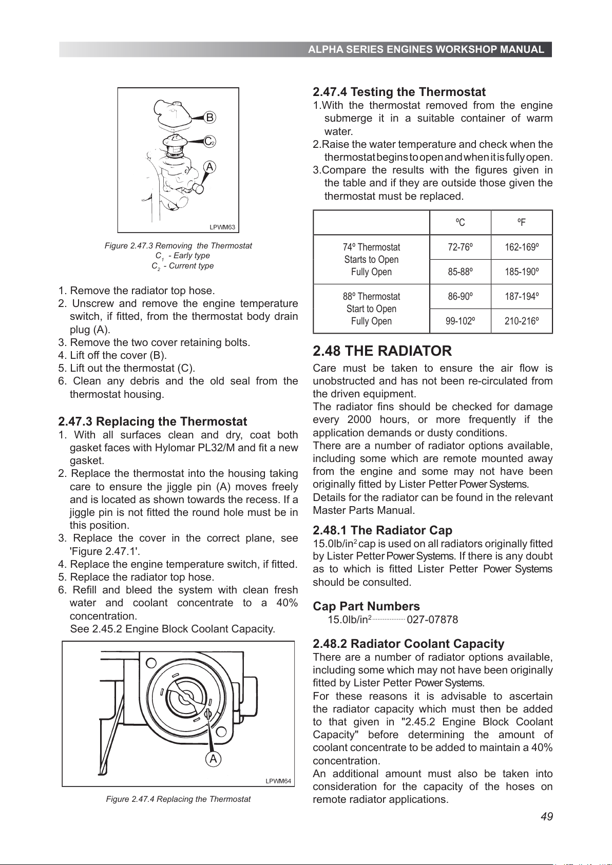
ALPHA SERIES ENGINES WORKSHOP MANUAL
49
Figure 2.47.3 Removing the Thermostat
C
1
- Early type
C
2
- Current type
1. Remove the radiator top hose.
2. Unscrew and remove the engine temperature
switch, if fitted, from the thermostat body drain
plug (A).
3. Remove the two cover retaining bolts.
4. Lift off the cover (B).
5. Lift out the thermostat (C).
6. Clean any debris and the old seal from the
thermostat housing.
2.47.3 Replacing the Thermostat
1. With all surfaces clean and dry, coat both
gasket faces with Hylomar PL32/M and fit a new
gasket.
2. Replace the thermostat into the housing taking
care to ensure the jiggle pin (A) moves freely
and is located as shown towards the recess. If a
jiggle pin is not fitted the round hole must be in
this position.
3. Replace the cover in the correct plane, see
'Figure 2.47.1'.
4. Replace the engine temperature switch, if fitted.
5. Replace the radiator top hose.
6. Refill and bleed the system with clean fresh
water and coolant concentrate to a 40%
concentration.
See 2.45.2 Engine Block Coolant Capacity.
Figure 2.47.4 Replacing the Thermostat
2.47.4 Testing the Thermostat
1.With the thermostat removed from the engine
submerge it in a suitable container of warm
water.
2.Raise the water temperature and check when the
thermostat begins to open and when it is fully open.
3.Compare the results with the figures given in
the table and if they are outside those given the
thermostat must be replaced.
ºC ºF
74º Thermostat
Starts to Open
Fully Open
72-76º 162-169º
85-88º 185-190º
88º Thermostat
Start to Open
Fully Open
86-90º 187-194º
99-102º 210-216º
2.48 THE RADIATOR
Care must be taken to ensure the air flow is
unobstructed and has not been re-circulated from
the driven equipment.
The radiator fins should be checked for damage
every 2000 hours, or more frequently if the
application demands or dusty conditions.
There are a number of radiator options available,
including some which are remote mounted away
from the engine and some may not have been
originally fitted by Lister Petter Power Systems.
Details for the radiator can be found in the relevant
Master Parts Manual.
2.48.1 The Radiator Cap
15.0lb/in2 cap is used on all radiators originally fitted
Cap Part Numbers
15.0lb/in
2 ...................
027-07878
2.48.2 Radiator Coolant Capacity
There are a number of radiator options available,
including some which may not have been originally
fitted by Lister Petter Power Systems.
For these reasons it is advisable to ascertain
the radiator capacity which must then be added
to that given in "2.45.2 Engine Block Coolant
Capacity" before determining the amount of
coolant concentrate to be added to maintain a 40%
concentration.
An additional amount must also be taken into
consideration for the capacity of the hoses on
remote radiator applications.
by Lister Petter Power Systems. If there is any doubt
as to which is fitted Lister Petter Power Systems
should be consulted.
All manuals and user guides at all-guides.com
Page 50
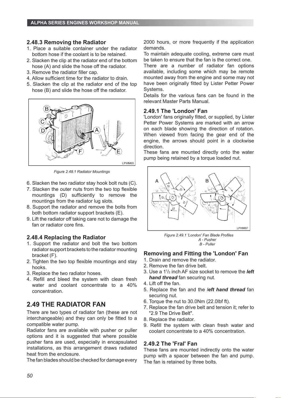
ALPHA SERIES ENGINES WORKSHOP MANUAL
50
2.48.3 Removing the Radiator
1. Place a suitable container under the radiator
bottom hose if the coolant is to be retained.
2. Slacken the clip at the radiator end of the bottom
hose (A) and slide the hose off the radiator.
3. Remove the radiator filler cap.
4. Allow sufficient time for the radiator to drain.
5. Slacken the clip at the radiator end of the top
hose (B) and slide the hose off the radiator.
Figure 2.48.1 Radiator Mountings
6. Slacken the two radiator stay hook bolt nuts (C).
7. Slacken the outer nuts from the two top flexible
mountings (D) sufficiently to remove the
mountings from the radiator lug slots.
8. Support the radiator and remove the bolts from
both bottom radiator support brackets (E).
9. Lift the radiator off taking care not to damage the
fan or radiator core fins.
2.48.4 Replacing the Radiator
1. Support the radiator and bolt the two bottom
radiator support brackets to the radiator mounting
bracket (F).
2. Tighten the two top flexible mountings and stay
hooks.
3. Replace the two radiator hoses.
4. Refill and bleed the system with clean fresh
water and coolant concentrate to a 40%
concentration.
2.49 THE RADIATOR FAN
There are two types of radiator fan (these are not
interchangeable) and they can only be fitted to a
compatible water pump.
Radiator fans are available with pusher or puller
options and it is suggested that where possible
pusher fans are used, especially in encapsulated
installations, as this arrangement draws radiated
heat from the enclosure.
The fan blades should be checked for damage every
2000 hours, or more frequently if the application
demands.
To maintain adequate cooling, extreme care must
be taken to ensure that the fan is the correct one.
2.49.1 The 'London' Fan
These fans are mounted directly onto the water
pump being retained by a torque loaded nut.
Figure 2.49.1 'London' Fan Blade Profiles
A - Pusher
B - Puller
Removing and Fitting the 'London' Fan
1. Drain and remove the radiator.
2. Remove the fan drive belt.
3. Use a 1
1
/2 inch AF size socket to remove the left
hand thread fan securing nut.
4. Lift off the fan.
5. Replace the fan and the left hand thread fan
securing nut.
6. Torque the nut to 30.0Nm (22.0lbf ft).
7. Replace the fan drive belt and tension it; refer to
"2.9 The Drive Belt".
8. Replace the radiator.
9. Refill the system with clean fresh water and
coolant concentrate to a 40% concentration.
2.49.2 The 'Fral' Fan
These fans are mounted indirectly onto the water
pump with a spacer between the fan and pump.
The fan is retained by three bolts.
There are a number of radiator fan options
available, including some which may be remote
mounted away from the engine and some may not
have been originally fitted by Lister Petter Power
Systems.
Details for the various fans can be found in the
relevant Master Parts Manual.
'London' fans originally fitted, or supplied, by Lister
Petter Power Systems are marked with an arrow
on each blade showing the direction of rotation.
When viewed from facing the gear end of the
engine, the arrows should point in a clockwise
direction.
All manuals and user guides at all-guides.com
Page 51
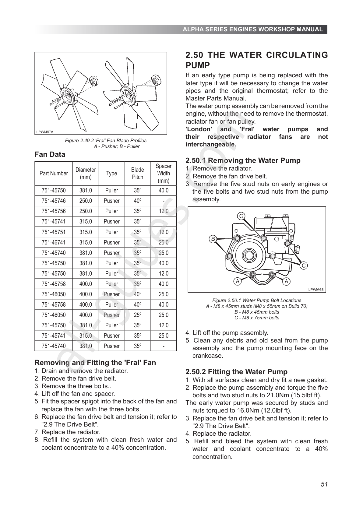
ALPHA SERIES ENGINES WORKSHOP MANUAL
51
Figure 2.49.2 'Fral' Fan Blade Proles
A - Pusher; B - Puller
Fan Data
Part Number
Diameter
(mm)
Type
Blade
Pitch
Spacer
Width
(mm)
751-45750 381.0 Puller 35º 40.0
751-45746 250.0 Pusher 40º -
751-45756 250.0 Puller 35º 12.0
751-45741 315.0 Pusher 35º -
751-45751 315.0 Puller 35º 12.0
751-46741 315.0 Pusher 35º 25.0
751-45740 381.0 Pusher 35º 25.0
751-45750 381.0 Puller 35º 40.0
751-45750 381.0 Puller 35º 12.0
751-45758 400.0 Puller 35º 40.0
751-46050 400.0 Pusher 40º 25.0
751-45758 400.0 Puller 40º 40.0
751-46050 400.0 Pusher 25º 25.0
751-45750 381.0 Puller 35º 12.0
751-45741 315.0 Pusher 35º 25.0
751-45740 381.0 Pusher 35º -
Removing and Fitting the 'Fral' Fan
1. Drain and remove the radiator.
2. Remove the fan drive belt.
3. Remove the three bolts..
4. Lift off the fan and spacer.
5. Fit the spacer spigot into the back of the fan and
replace the fan with the three bolts.
6. Replace the fan drive belt and tension it; refer to
"2.9 The Drive Belt".
7. Replace the radiator.
8. Rell the system with clean fresh water and
coolant concentrate to a 40% concentration.
2.50 THE WATER CIRCULATING
PUMP
If an early type pump is being replaced with the
later type it will be necessary to change the water
pipes and the original thermostat; refer to the
Master Parts Manual.
The water pump assembly can be removed from the
engine, without the need to remove the thermostat,
radiator fan or fan pulley.
'London' and 'Fral' water pumps and
their respective radiator fans are not
interchangeable.
2.50.1 Removing the Water Pump
1. Remove the radiator.
2. Remove the fan drive belt.
3. Remove the ve stud nuts on early engines or
the ve bolts and two stud nuts from the pump
assembly.
Figure 2.50.1 Water Pump Bolt Locations
A - M8 x 45mm studs (M8 x 55mm on Build 70)
B - M8 x 45mm bolts
C - M8 x 75mm bolts
4. Lift off the pump assembly.
5. Clean any debris and old seal from the pump
assembly and the pump mounting face on the
crankcase.
2.50.2 Fitting the Water Pump
1. With all surfaces clean and dry t a new gasket.
2. Replace the pump assembly and torque the ve
bolts and two stud nuts to 21.0Nm (15.5lbf ft).
The early water pump was secured by studs and
nuts torqued to 16.0Nm (12.0lbf ft).
3. Replace the fan drive belt and tension it; refer to
"2.9 The Drive Belt".
4. Replace the radiator.
5. Rell and bleed the system with clean fresh
water and coolant concentrate to a 40%
concentration.
All manuals and user guides at all-guides.com
all-guides.com
Page 52
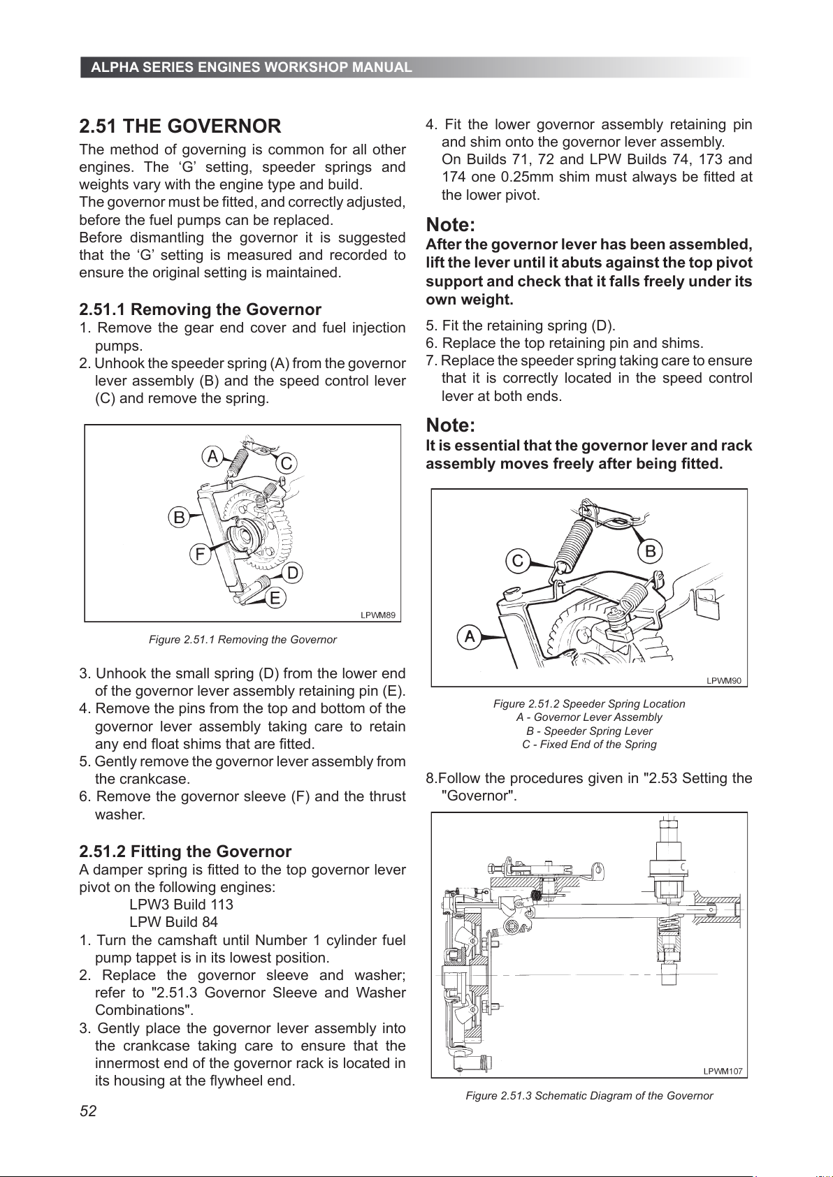
ALPHA SERIES ENGINES WORKSHOP MANUAL
52
2.51 THE GOVERNOR
The method of governing is common for all other
engines. The ‘G’ setting, speeder springs and
weights vary with the engine type and build.
The governor must be tted, and correctly adjusted,
before the fuel pumps can be replaced.
Before dismantling the governor it is suggested
that the ‘G’ setting is measured and recorded to
ensure the original setting is maintained.
2.51.1 Removing the Governor
1. Remove the gear end cover and fuel injection
pumps.
2. Unhook the speeder spring (A) from the governor
lever assembly (B) and the speed control lever
(C) and remove the spring.
Figure 2.51.1 Removing the Governor
3. Unhook the small spring (D) from the lower end
of the governor lever assembly retaining pin (E).
4. Remove the pins from the top and bottom of the
governor lever assembly taking care to retain
any end oat shims that are tted.
5. Gently remove the governor lever assembly from
the crankcase.
6. Remove the governor sleeve (F) and the thrust
washer.
2.51.2 Fitting the Governor
A damper spring is tted to the top governor lever
pivot on the following engines:
LPW3 Build 113
LPW Build 84
1. Turn the camshaft until Number 1 cylinder fuel
pump tappet is in its lowest position.
2. Replace the governor sleeve and washer;
refer to "2.51.3 Governor Sleeve and Washer
Combinations".
3. Gently place the governor lever assembly into
the crankcase taking care to ensure that the
innermost end of the governor rack is located in
its housing at the ywheel end.
4. Fit the lower governor assembly retaining pin
and shim onto the governor lever assembly.
On Builds 71, 72 and LPW Builds 74, 173 and
174 one 0.25mm shim must always be tted at
the lower pivot.
Note:
After the governor lever has been assembled,
lift the lever until it abuts against the top pivot
support and check that it falls freely under its
own weight.
5. Fit the retaining spring (D).
6. Replace the top retaining pin and shims.
7. Replace the speeder spring taking care to ensure
that it is correctly located in the speed control
lever at both ends.
Note:
It is essential that the governor lever and rack
assembly moves freely after being tted.
Figure 2.51.2 Speeder Spring Location
A - Governor Lever Assembly
B - Speeder Spring Lever
C - Fixed End of the Spring
8.Follow the procedures given in "2.53 Setting the
"Governor".
Figure 2.51.3 Schematic Diagram of the Governor
All manuals and user guides at all-guides.com
Page 53
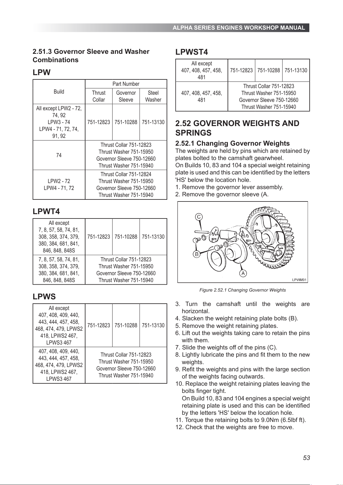
ALPHA SERIES ENGINES WORKSHOP MANUAL
53
2.51.3 Governor Sleeve and Washer
Combinations
LPW
Build
Part Number
Thrust
Collar
Governor
Sleeve
Steel
Washer
All except LPW2 - 72,
74, 92
LPW3 - 74
LPW4 - 71, 72, 74,
91, 92
751-12823 751-10288 751-13130
74
Thrust Collar 751-12823
Thrust Washer 751-15950
Governor Sleeve 750-12660
Thrust Washer 751-15940
LPW2 - 72
LPW4 - 71, 72
Thrust Collar 751-12824
Thrust Washer 751-15950
Governor Sleeve 750-12660
Thrust Washer 751-15940
LPWT4
All except
7, 8, 57, 58, 74, 81,
308, 358, 374, 379,
380, 384, 681, 841,
846, 848, 848S
751-12823 751-10288 751-13130
7, 8, 57, 58, 74, 81,
308, 358, 374, 379,
380, 384, 681, 841,
846, 848, 848S
Thrust Collar 751-12823
Thrust Washer 751-15950
Governor Sleeve 750-12660
Thrust Washer 751-15940
LPWS
All except
407, 408, 409, 440,
443, 444, 457, 458,
468, 474, 479, LPWS2
418, LPWS2 467,
LPWS3 467
751-12823 751-10288 751-13130
407, 408, 409, 440,
443, 444, 457, 458,
468, 474, 479, LPWS2
418, LPWS2 467,
LPWS3 467
Thrust Collar 751-12823
Thrust Washer 751-15950
Governor Sleeve 750-12660
Thrust Washer 751-15940
LPWST4
All except
407, 408, 457, 458,
481
751-12823 751-10288 751-13130
407, 408, 457, 458,
481
Thrust Collar 751-12823
Thrust Washer 751-15950
Governor Sleeve 750-12660
Thrust Washer 751-15940
2.52 GOVERNOR WEIGHTS AND
SPRINGS
2.52.1 Changing Governor Weights
The weights are held by pins which are retained by
plates bolted to the camshaft gearwheel.
On Builds 10, 83 and 104 a special weight retaining
plate is used and this can be identied by the letters
'HS' below the location hole.
1. Remove the governor lever assembly.
2. Remove the governor sleeve (A.
Figure 2.52.1 Changing Governor Weights
3. Turn the camshaft until the weights are
horizontal.
4. Slacken the weight retaining plate bolts (B).
5. Remove the weight retaining plates.
6. Lift out the weights taking care to retain the pins
with them.
7. Slide the weights off of the pins (C).
8. Lightly lubricate the pins and t them to the new
weights.
9. Ret the weights and pins with the large section
of the weights facing outwards.
10. Replace the weight retaining plates leaving the
bolts nger tight.
On Build 10, 83 and 104 engines a special weight
retaining plate is used and this can be identied
by the letters 'HS' below the location hole.
11. Torque the retaining bolts to 9.0Nm (6.5lbf ft).
12. Check that the weights are free to move.
All manuals and user guides at all-guides.com
Page 54
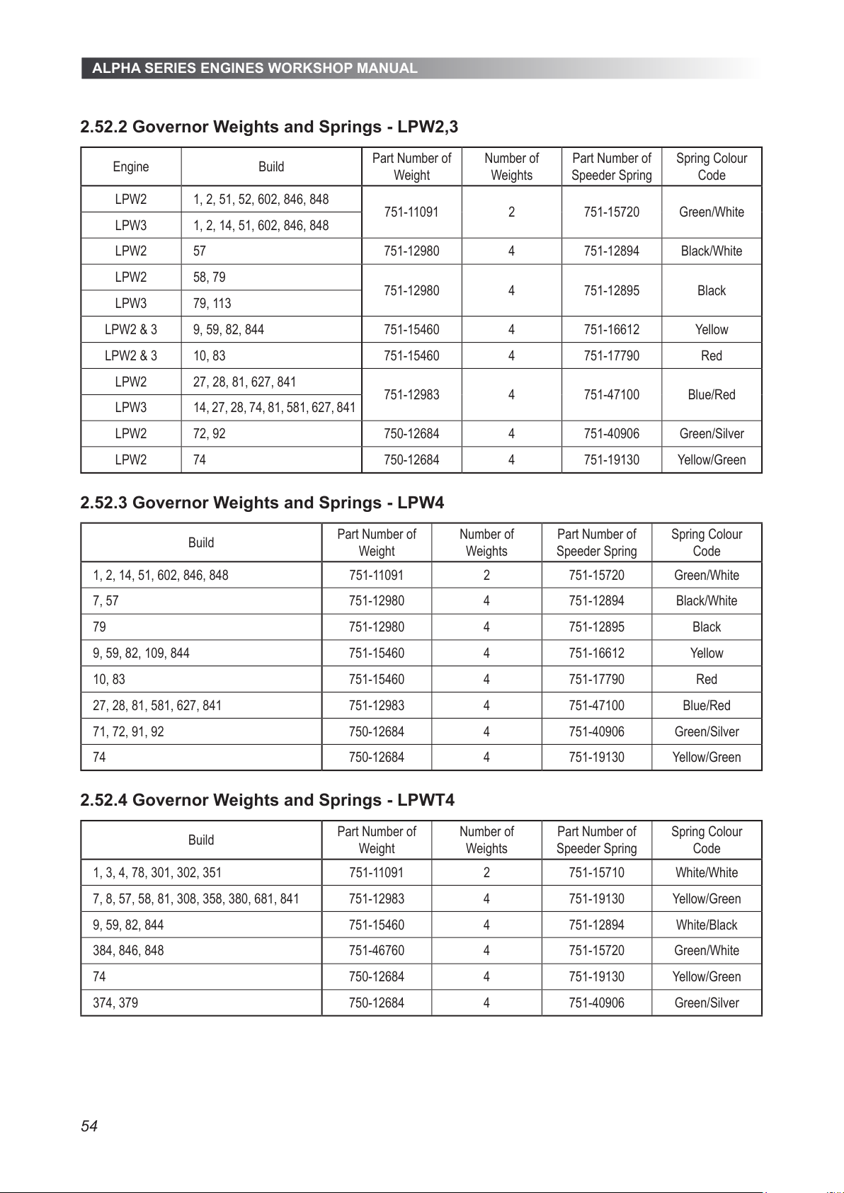
ALPHA SERIES ENGINES WORKSHOP MANUAL
54
2.52.2 Governor Weights and Springs - LPW2,3
Engine Build
Part Number of
Weight
Number of
Weights
Part Number of
Speeder Spring
Spring Colour
Code
LPW2 1, 2, 51, 52, 602, 846, 848
751-11091 2 751-15720 Green/White
LPW3 1, 2, 14, 51, 602, 846, 848
LPW2 57 751-12980 4 751-12894 Black/White
LPW2 58, 79
751-12980 4 751-12895 Black
LPW3 79, 113
LPW2 & 3 9, 59, 82, 844 751-15460 4 751-16612 Yellow
LPW2 & 3 10, 83 751-15460 4 751-17790 Red
LPW2 27, 28, 81, 627, 841
751-12983 4 751-47100 Blue/Red
LPW3 14, 27, 28, 74, 81, 581, 627, 841
LPW2 72, 92 750-12684 4 751-40906 Green/Silver
LPW2 74 750-12684 4 751-19130 Yellow/Green
2.52.3 Governor Weights and Springs - LPW4
Build
Part Number of
Weight
Number of
Weights
Part Number of
Speeder Spring
Spring Colour
Code
1, 2, 14, 51, 602, 846, 848 751-11091 2 751-15720 Green/White
7, 57 751-12980 4 751-12894 Black/White
79 751-12980 4 751-12895 Black
9, 59, 82, 109, 844 751-15460 4 751-16612 Yellow
10, 83 751-15460 4 751-17790 Red
27, 28, 81, 581, 627, 841 751-12983 4 751-47100 Blue/Red
71, 72, 91, 92 750-12684 4 751-40906 Green/Silver
74 750-12684 4 751-19130 Yellow/Green
2.52.4 Governor Weights and Springs - LPWT4
Build
Part Number of
Weight
Number of
Weights
Part Number of
Speeder Spring
Spring Colour
Code
1, 3, 4, 78, 301, 302, 351 751-11091 2 751-15710 White/White
7, 8, 57, 58, 81, 308, 358, 380, 681, 841 751-12983 4 751-19130 Yellow/Green
9, 59, 82, 844 751-15460 4 751-12894 White/Black
384, 846, 848 751-46760 4 751-15720 Green/White
74 750-12684 4 751-19130 Yellow/Green
374, 379 750-12684 4 751-40906 Green/Silver
All manuals and user guides at all-guides.com
Page 55
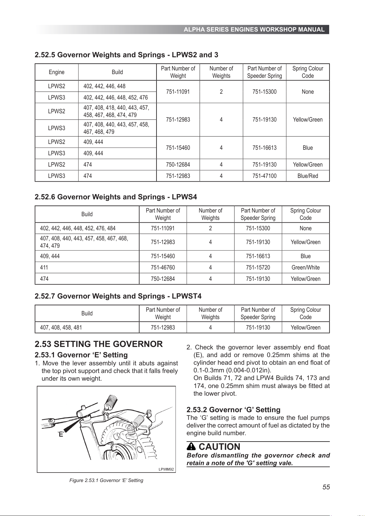
ALPHA SERIES ENGINES WORKSHOP MANUAL
55
2.52.5 Governor Weights and Springs - LPWS2 and 3
Engine Build
Part Number of
Weight
Number of
Weights
Part Number of
Speeder Spring
Spring Colour
Code
LPWS2 402, 442, 446, 448
751-11091 2 751-15300 None
LPWS3 402, 442, 446, 448, 452, 476
LPWS2
407, 408, 418, 440, 443, 457,
458, 467, 468, 474, 479
751-12983 4 751-19130 Yellow/Green
LPWS3
407, 408, 440, 443, 457, 458,
467, 468, 479
LPWS2 409, 444
751-15460 4 751-16613 Blue
LPWS3 409, 444
LPWS2 474 750-12684 4 751-19130 Yellow/Green
LPWS3 474 751-12983 4 751-47100 Blue/Red
2.52.6 Governor Weights and Springs - LPWS4
Build
Part Number of
Weight
Number of
Weights
Part Number of
Speeder Spring
Spring Colour
Code
402, 442, 446, 448, 452, 476, 484 751-11091 2 751-15300 None
407, 408, 440, 443, 457, 458, 467, 468,
474, 479
751-12983 4 751-19130 Yellow/Green
409, 444 751-15460 4 751-16613 Blue
411 751-46760 4 751-15720 Green/White
474 750-12684 4 751-19130 Yellow/Green
2.52.7 Governor Weights and Springs - LPWST4
Build
Part Number of
Weight
Number of
Weights
Part Number of
Speeder Spring
Spring Colour
Code
407, 408, 458, 481 751-12983 4 751-19130 Yellow/Green
2.53 SETTING THE GOVERNOR
2.53.1 Governor ‘E’ Setting
1. Move the lever assembly until it abuts against
the top pivot support and check that it falls freely
under its own weight.
Figure 2.53.1 Governor ‘E’ Setting
2. Check the governor lever assembly end oat
(E), and add or remove 0.25mm shims at the
cylinder head end pivot to obtain an end oat of
0.1-0.3mm (0.004-0.012in).
On Builds 71, 72 and LPW4 Builds 74, 173 and
174, one 0.25mm shim must always be tted at
the lower pivot.
2.53.2 Governor ‘G’ Setting
The ‘G’ setting is made to ensure the fuel pumps
deliver the correct amount of fuel as dictated by the
engine build number.
CAUTION
Before dismantling the governor check and
retain a note of the 'G' setting vale.
All manuals and user guides at all-guides.com
Page 56
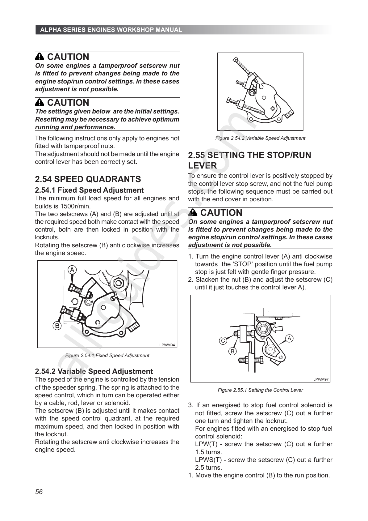
ALPHA SERIES ENGINES WORKSHOP MANUAL
56
CAUTION
On some engines a tamperproof setscrew nut
is tted to prevent changes being made to the
engine stop/run control settings. In these cases
adjustment is not possible.
CAUTION
The settings given below are the initial settings.
Resetting may be necessary to achieve optimum
running and performance.
The following instructions only apply to engines not
tted with tamperproof nuts.
The adjustment should not be made until the engine
control lever has been correctly set.
2.54 SPEED QUADRANTS
2.54.1 Fixed Speed Adjustment
The minimum full load speed for all engines and
builds is 1500r/min.
The two setscrews (A) and (B) are adjusted until at
the required speed both make contact with the speed
control, both are then locked in position with the
locknuts.
Rotating the setscrew (B) anti clockwise increases
the engine speed.
Figure 2.54.1 Fixed Speed Adjustment
2.54.2 Variable Speed Adjustment
The speed of the engine is controlled by the tension
of the speeder spring. The spring is attached to the
speed control, which in turn can be operated either
by a cable, rod, lever or solenoid.
The setscrew (B) is adjusted until it makes contact
with the speed control quadrant, at the required
maximum speed, and then locked in position with
the locknut.
Rotating the setscrew anti clockwise increases the
engine speed.
Figure 2.54.2 Variable Speed Adjustment
2.55 SETTING THE STOP/RUN
LEVER
To ensure the control lever is positively stopped by
the control lever stop screw, and not the fuel pump
stops, the following sequence must be carried out
with the end cover in position.
CAUTION
On some engines a tamperproof setscrew nut
is tted to prevent changes being made to the
engine stop/run control settings. In these cases
adjustment is not possible.
1. Turn the engine control lever (A) anti clockwise
towards the 'STOP' position until the fuel pump
stop is just felt with gentle nger pressure.
2. Slacken the nut (B) and adjust the setscrew (C)
until it just touches the control lever A).
Figure 2.55.1 Setting the Control Lever
3. If an energised to stop fuel control solenoid is
not tted, screw the setscrew (C) out a further
one turn and tighten the locknut.
For engines tted with an energised to stop fuel
control solenoid:
LPW(T) - screw the setscrew (C) out a further
1.5 turns.
LPWS(T) - screw the setscrew (C) out a further
2.5 turns.
1. Move the engine control (B) to the run position.
All manuals and user guides at all-guides.com
all-guides.com
Page 57
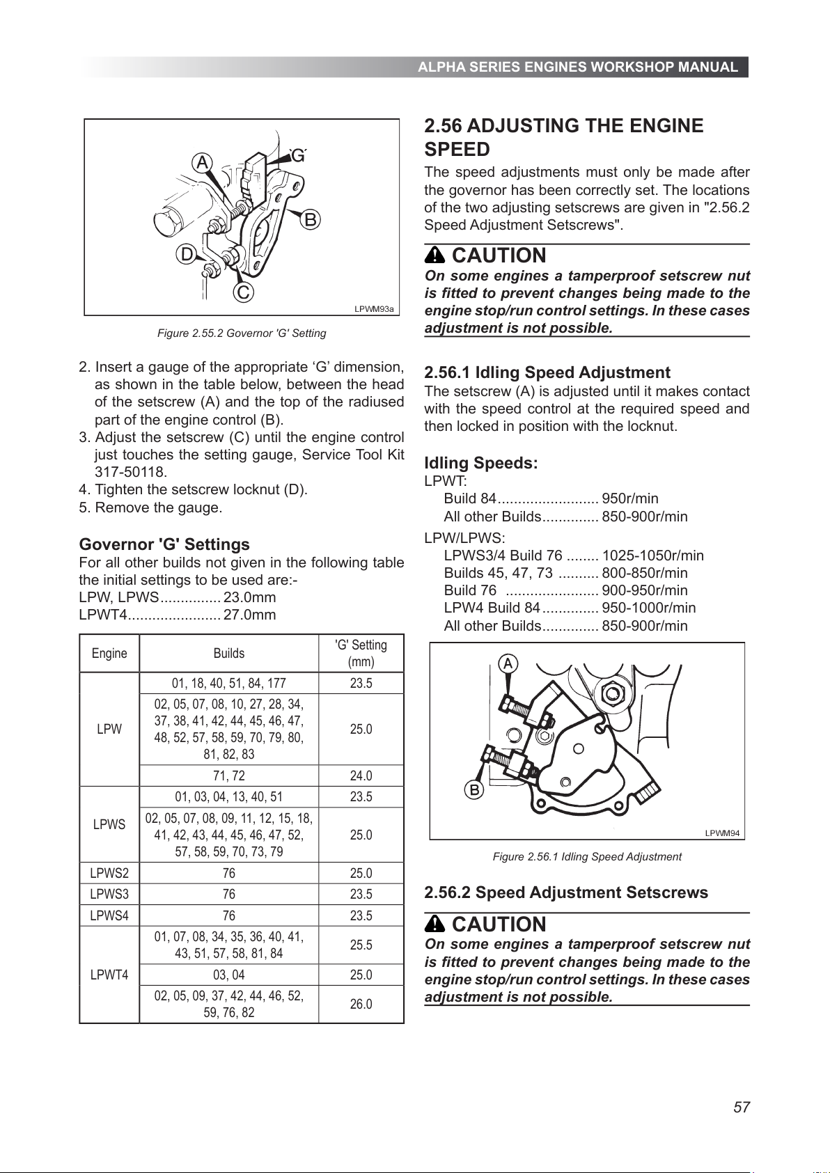
ALPHA SERIES ENGINES WORKSHOP MANUAL
57
Figure 2.55.2 Governor 'G' Setting
2. Insert a gauge of the appropriate ‘G’ dimension,
as shown in the table below, between the head
of the setscrew (A) and the top of the radiused
part of the engine control (B).
3. Adjust the setscrew (C) until the engine control
just touches the setting gauge, Service Tool Kit
317-50118.
4. Tighten the setscrew locknut (D).
5. Remove the gauge.
Governor 'G' Settings
For all other builds not given in the following table
the initial settings to be used are:-
LPW, LPWS ............... 23.0mm
LPWT4....................... 27.0mm
Engine Builds
'G' Setting
(mm)
LPW
01, 18, 40, 51, 84, 177 23.5
02, 05, 07, 08, 10, 27, 28, 34,
37, 38, 41, 42, 44, 45, 46, 47,
48, 52, 57, 58, 59, 70, 79, 80,
81, 82, 83
25.0
71, 72 24.0
LPWS
01, 03, 04, 13, 40, 51 23.5
02, 05, 07, 08, 09, 11, 12, 15, 18,
41, 42, 43, 44, 45, 46, 47, 52,
57, 58, 59, 70, 73, 79
25.0
LPWS2 76 25.0
LPWS3 76 23.5
LPWS4 76 23.5
LPWT4
01, 07, 08, 34, 35, 36, 40, 41,
43, 51, 57, 58, 81, 84
25.5
03, 04 25.0
02, 05, 09, 37, 42, 44, 46, 52,
59, 76, 82
26.0
2.56 ADJUSTING THE ENGINE
SPEED
The speed adjustments must only be made after
the governor has been correctly set. The locations
of the two adjusting setscrews are given in "2.56.2
Speed Adjustment Setscrews".
CAUTION
On some engines a tamperproof setscrew nut
is tted to prevent changes being made to the
engine stop/run control settings. In these cases
adjustment is not possible.
2.56.1 Idling Speed Adjustment
The setscrew (A) is adjusted until it makes contact
with the speed control at the required speed and
then locked in position with the locknut.
Idling Speeds:
LPWT:
Build 84 ......................... 950r/min
All other Builds .............. 850-900r/min
LPW/LPWS:
LPWS3/4 Build 76 ........ 1025-1050r/min
Builds 45, 47, 73 .......... 800-850r/min
Build 76 ....................... 900-950r/min
LPW4 Build 84 .............. 950-1000r/min
All other Builds .............. 850-900r/min
Figure 2.56.1 Idling Speed Adjustment
2.56.2 Speed Adjustment Setscrews
CAUTION
On some engines a tamperproof setscrew nut
is tted to prevent changes being made to the
engine stop/run control settings. In these cases
adjustment is not possible.
All manuals and user guides at all-guides.com
Page 58
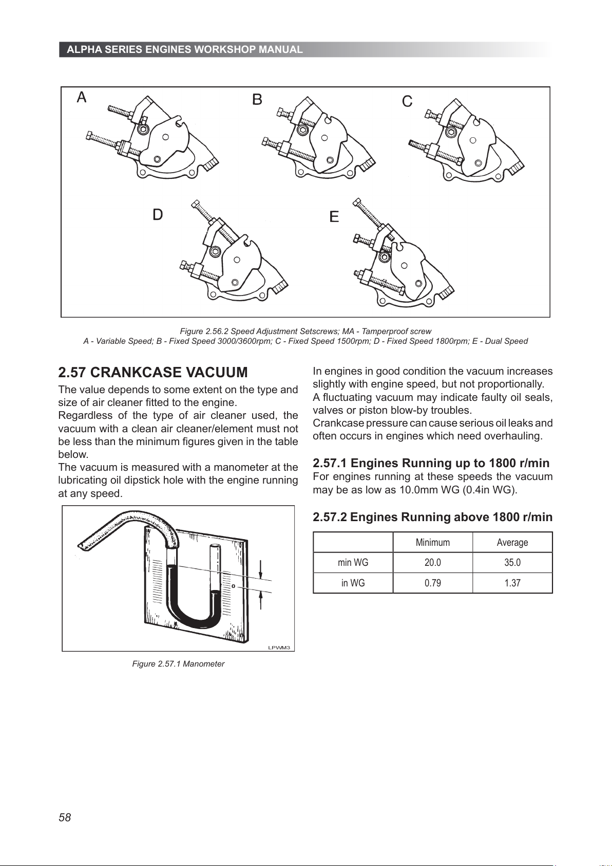
ALPHA SERIES ENGINES WORKSHOP MANUAL
58
2.57 CRANKCASE VACUUM
The value depends to some extent on the type and
size of air cleaner tted to the engine.
Regardless of the type of air cleaner used, the
vacuum with a clean air cleaner/element must not
be less than the minimum gures given in the table
below.
The vacuum is measured with a manometer at the
lubricating oil dipstick hole with the engine running
at any speed.
Figure 2.57.1 Manometer
In engines in good condition the vacuum increases
slightly with engine speed, but not proportionally.
A uctuating vacuum may indicate faulty oil seals,
valves or piston blow-by troubles.
Crankcase pressure can cause serious oil leaks and
often occurs in engines which need overhauling.
2.57.1 Engines Running up to 1800 r/min
For engines running at these speeds the vacuum
may be as low as 10.0mm WG (0.4in WG).
2.57.2 Engines Running above 1800 r/min
Minimum Average
min WG 20.0 35.0
in WG 0.79 1.37
Figure 2.56.2 Speed Adjustment Setscrews; MA - Tamperproof screw
A - Variable Speed; B - Fixed Speed 3000/3600rpm; C - Fixed Speed 1500rpm; D - Fixed Speed 1800rpm; E - Dual Speed
All manuals and user guides at all-guides.com
Page 59
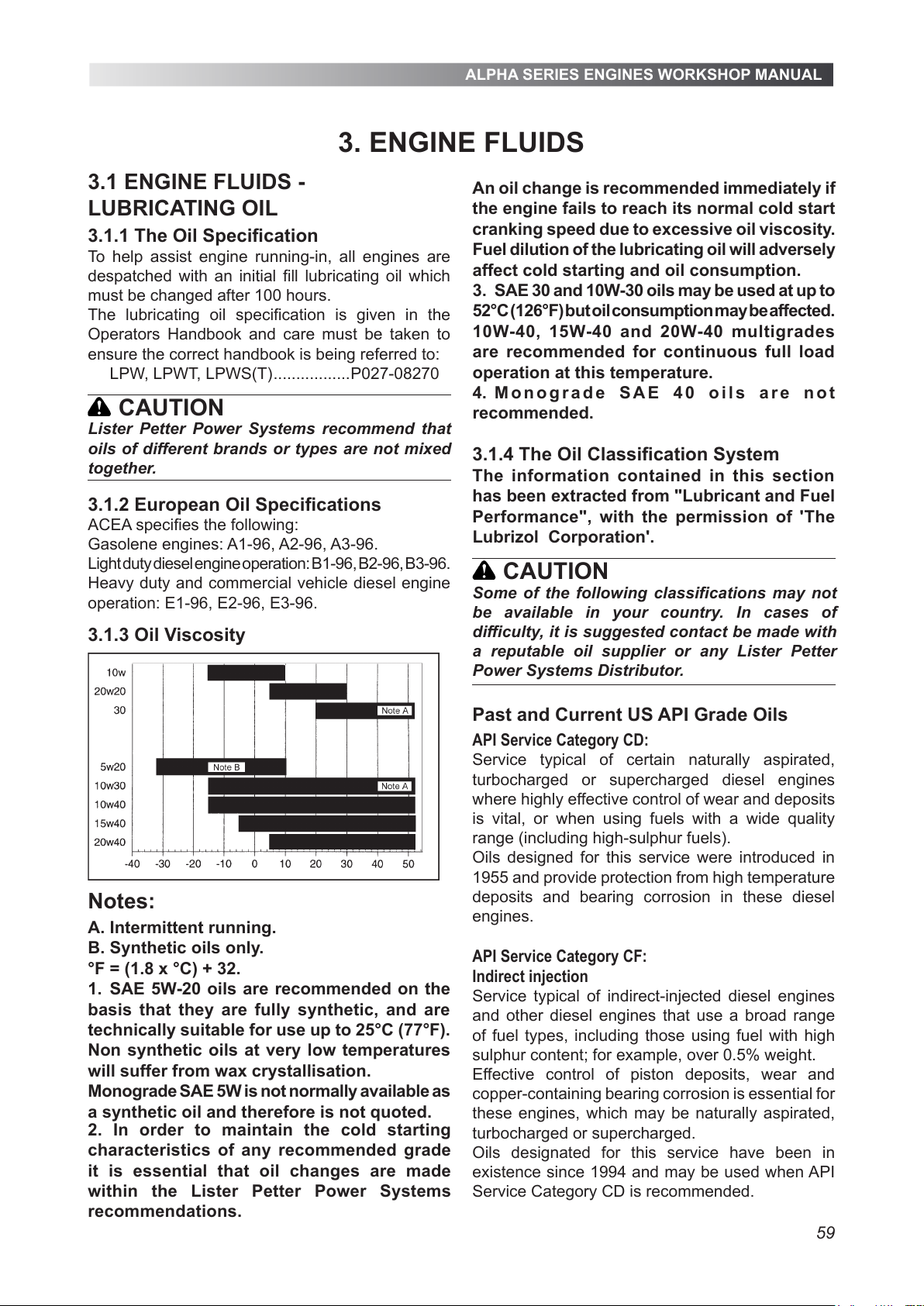
ALPHA SERIES ENGINES WORKSHOP MANUAL
59
3.1 ENGINE FLUIDS -
LUBRICATING OIL
3.1.1 The Oil Specification
To help assist engine running-in, all engines are
despatched with an initial fill lubricating oil which
must be changed after 100 hours.
The lubricating oil specification is given in the
Operators Handbook and care must be taken to
ensure the correct handbook is being referred to:
LPW, LPWT, LPWS(T) .................P027-08270
CAUTION
3.1.2 European Oil Specifications
ACEA specifies the following:
Gasolene engines: A1-96, A2-96, A3-96.
Light duty diesel engine operation: B1-96, B2-96, B3-96.
Heavy duty and commercial vehicle diesel engine
operation: E1-96, E2-96, E3-96.
3.1.3 Oil Viscosity
Notes:
A. Intermittent running.
B. Synthetic oils only.
°F = (1.8 x °C) + 32.
1. SAE 5W-20 oils are recommended on the
basis that they are fully synthetic, and are
technically suitable for use up to 25°C (77°F).
Non synthetic oils at very low temperatures
will suffer from wax crystallisation.
Monograde SAE 5W is not normally available as
a synthetic oil and therefore is not quoted.
An oil change is recommended immediately if
the engine fails to reach its normal cold start
cranking speed due to excessive oil viscosity.
Fuel dilution of the lubricating oil will adversely
affect cold starting and oil consumption.
3. SAE 30 and 10W-30 oils may be used at up to
52°C (126°F) but oil consumption may be affected.
10W-40, 15W-40 and 20W-40 multigrades
are recommended for continuous full load
operation at this temperature.
4. M onograd e S A E 40 oils are not
recommended.
3.1.4 The Oil Classification System
The information contained in this section
has been extracted from "Lubricant and Fuel
Performance", with the permission of 'The
Lubrizol Corporation'.
CAUTION
Past and Current US API Grade Oils
API Service Category CD:
Service typical of certain naturally aspirated,
turbocharged or supercharged diesel engines
where highly effective control of wear and deposits
is vital, or when using fuels with a wide quality
range (including high-sulphur fuels).
Oils designed for this service were introduced in
1955 and provide protection from high temperature
deposits and bearing corrosion in these diesel
engines.
API Service Category CF:
Indirect injection
Service typical of indirect-injected diesel engines
and other diesel engines that use a broad range
of fuel types, including those using fuel with high
sulphur content; for example, over 0.5% weight.
Effective control of piston deposits, wear and
copper-containing bearing corrosion is essential for
these engines, which may be naturally aspirated,
turbocharged or supercharged.
Oils designated for this service have been in
existence since 1994 and may be used when API
Service Category CD is recommended.
3. ENGINE FLUIDS
Lister Petter Power Systems recommend that
oils of different brands or types are not mixed
together.
Some of the following classifications may not
be available in your country. In cases of
difficulty, it is suggested contact be made with
a reputable oil supplier or any Lister Petter
Power Systems Distributor.
2. In order to maintain the cold starting
characteristics of any recommended grade
it is essential that oil changes are made
within the Lister Petter Power Systems
recommendations.
All manuals and user guides at all-guides.com
Page 60
ALPHA SERIES ENGINES WORKSHOP MANUAL
60
API Service Category CF-2:
Severe duty, two-stroke cycle
Service typical of two-stroke cycle diesel engines
requiring highly effective control over cylinder and
ring-face scufng and deposits.
Oils designed for this service have been in existence
since 1994 and may also be used when API Engine
Service Category CD-11 is recommended.
These oils do not necessarily meet the requirements
of API CF or CF-4 unless they pass the test
requirements for these categories.
API Service Category CG-4 - 1994:
Severe duty
API Service Category CG-4 describes oils for use in
high-speed four-stroke-cycle diesel engines used in
both heavy-duty on-highway (0.05% weight sulphur
fuel) and off-highway (less than 0.5% weight
sulphur fuel) applications.
CG-4 oils provide effective control over
high-temperature piston deposits, wear,
corrosion, foaming, oxidation stability, and soot
accumulation.
These oils are especially effective in engines
designed to meet 1994 exhaust emission standards
and may also be used in engines requiring API
Service Categories CD, CE, and CF-4. Oils designed
for this service have been in existence since 1994.
3.2 ENGINE FLUIDS - FUEL
3.2.1 The Fuel Specication
The engine must only be used with diesel fuel oil
which conforms to one of the following:
a. BS 2869:1988 Class A2.
b. BS EN590:1995 Class A1.
c. USA Specication ASTM D-975-77 Grades
No.1-D and 2-D.
d. BSMA 100 Class M1 for marine use.
The fuel must be a distillate, and not a residual oil
or blend.
Vaporising oils are not suitable as fuels for Lister
Petter engines.
The user is cautioned that although the engines may
operate on fuels outside the above specications,
such operation may well result in excessive wear
and damage.
CAUTION
The fuel injection equipment is manufactured
to very accurate limits and the smallest particle
of dirt will destroy its efficiency. Fuel free
from water and contaminants is of the utmost
importance.
3.2.2 Low Temperature Fuels
Special winter fuels are often available for use at
ambient temperatures below 0°C (32°F).
These fuels have a lower viscosity and limit the
formation of wax at low ambient temperatures.
CAUTION
Wax formation can rapidly reduce the ow of
fuel through the fuel lter element.
3.3 ENGINE FLUIDS - COOLANT
CONCENTRATE
Traditionally the term ‘antifreeze’ has been used
to describe the concentrate which is added to
the cooling system. However, this term takes into
account only the frost-protective role of the product,
so implying that its use is a seasonal requirement,
and ignores its function as a heat exchange
medium which is designed to protect the system
from corrosion and damage under all operating
conditions.
The term ‘engine coolant concentrate’ embraces
all these requirements.
WARNING
Coolant concentrate must not be allowed to
come into contact with the skin; adhere to the
manufacturers instructions and precautions.
3.3.1 Concentrate Specication
Lister Petter engines are often built with aluminium
core radiators rather than copper nowadays. In
order to protect and ensure the longevity of all water
system components, the water used is critical. Like
vehicle manufacturers we are now recommending
mixing de-ionized or distilled water with your
antifreeze or coolant inhibitor.
When topping up or relling the engine’s water
system, do not use tap water, typical minerals and
ions found in tap water can be corrosive to internal
engine components including radiators, and can
cause a more rapid depletion of the anti-corrosion
additives found in most antifreeze.
Action required:
Refer to your coolant additive manufacturer to
establish the lower temperature operating range if
appropriate.
When topping up coolant please ensure that the
“top up” is of the correct concentrate mix and not
just water. It is recommended that this process is
repeated at minimum 12 month service intervals.
The specication of the coolant concentrate should
comply with one of the following:
BS6580 : 1985; MIL-A-11755D; MIL-A-46153/B.
All manuals and user guides at all-guides.com
Page 61
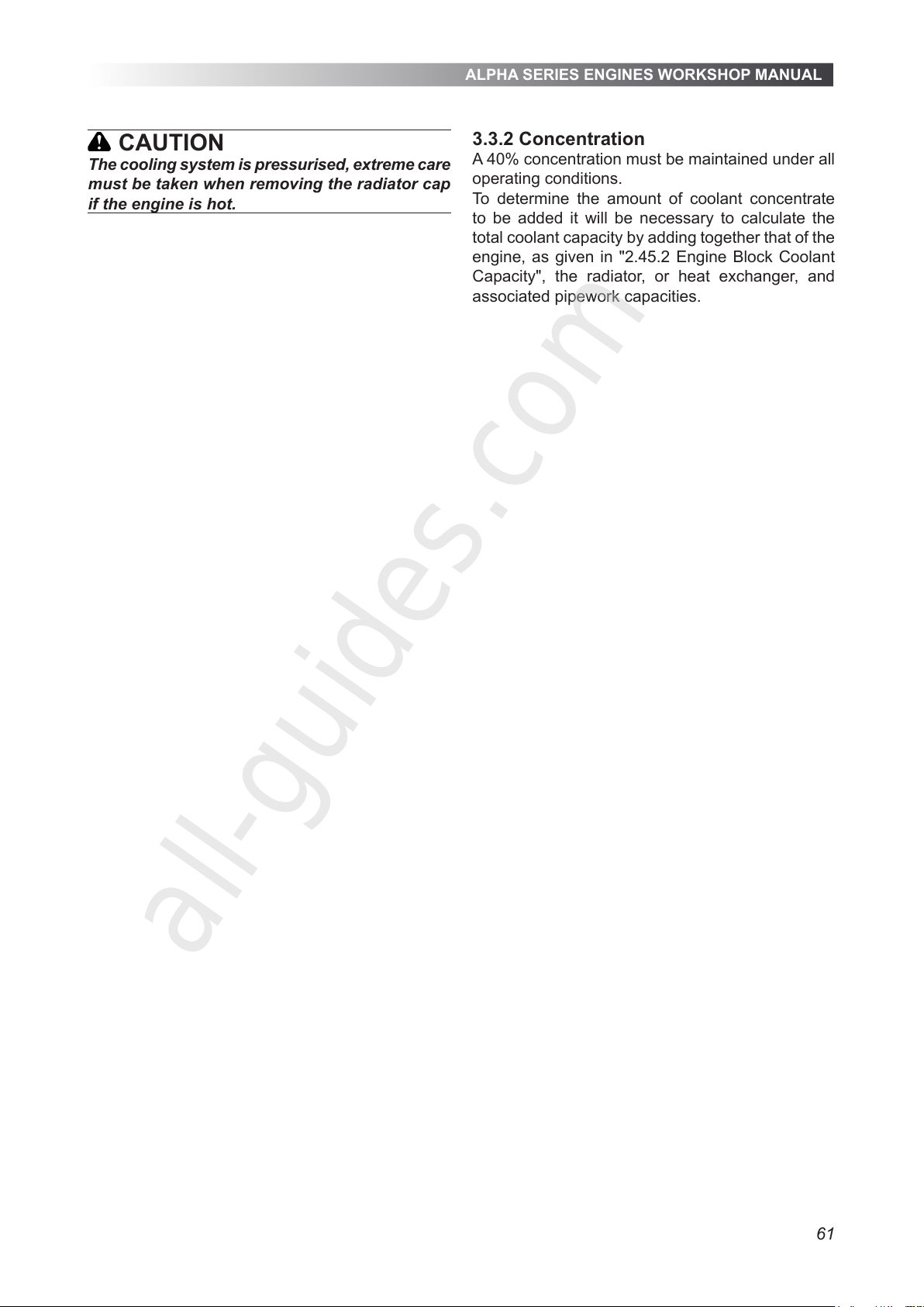
ALPHA SERIES ENGINES WORKSHOP MANUAL
61
CAUTION
The cooling system is pressurised, extreme care
must be taken when removing the radiator cap
if the engine is hot.
3.3.2 Concentration
A 40% concentration must be maintained under all
operating conditions.
To determine the amount of coolant concentrate
to be added it will be necessary to calculate the
total coolant capacity by adding together that of the
engine, as given in "2.45.2 Engine Block Coolant
Capacity", the radiator, or heat exchanger, and
associated pipework capacities.
All manuals and user guides at all-guides.com
all-guides.com
Page 62
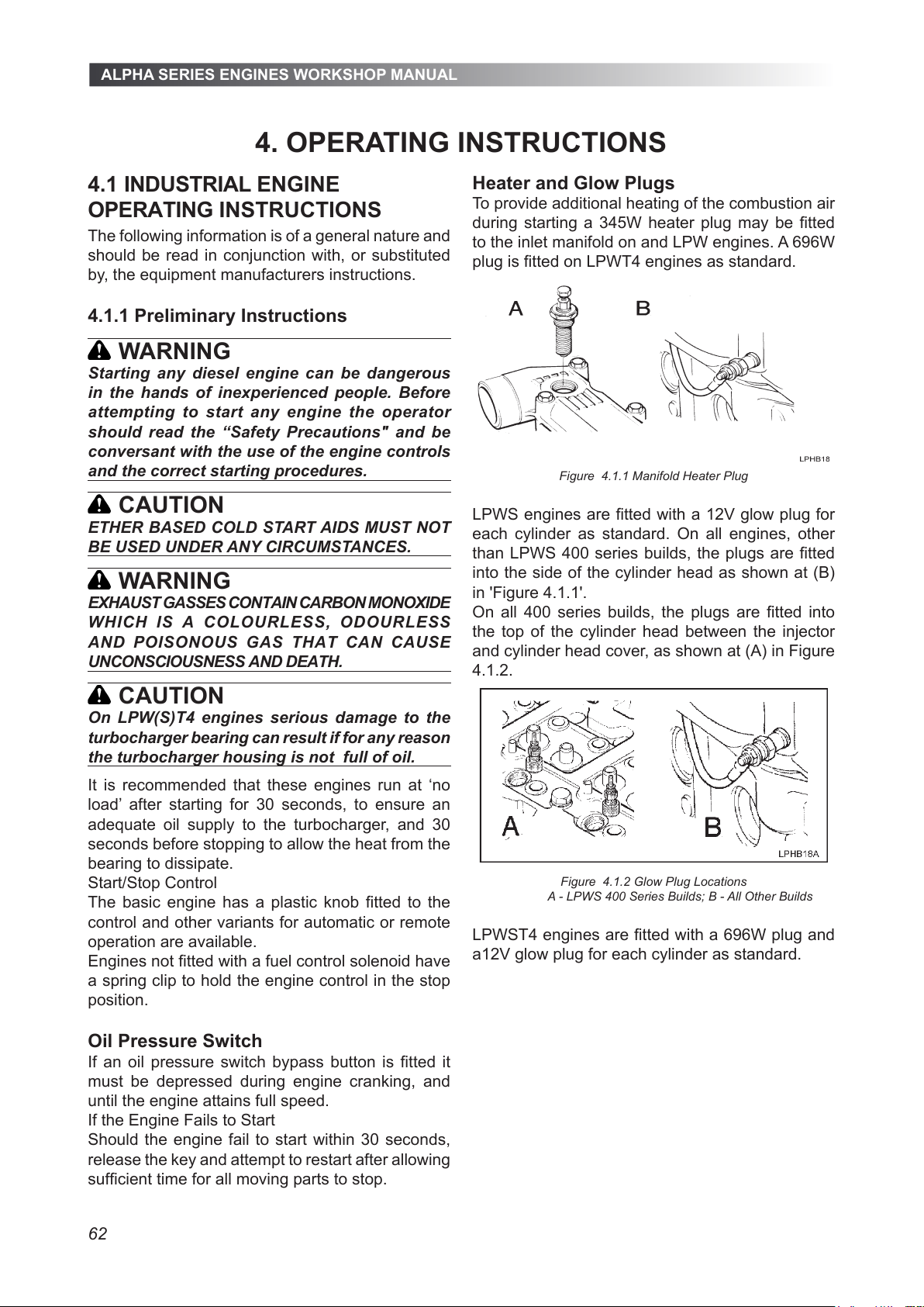
ALPHA SERIES ENGINES WORKSHOP MANUAL
62
4.1 INDUSTRIAL ENGINE
OPERATING INSTRUCTIONS
The following information is of a general nature and
should be read in conjunction with, or substituted
by, the equipment manufacturers instructions.
4.1.1 Preliminary Instructions
WARNING
Starting any diesel engine can be dangerous
in the hands of inexperienced people. Before
attempting to start any engine the operator
should read the “Safety Precautions" and be
conversant with the use of the engine controls
and the correct starting procedures.
CAUTION
ETHER BASED COLD START AIDS MUST NOT
BE USED UNDER ANY CIRCUMSTANCES.
WARNING
EXHAUST GASSES CONTAIN CARBON MONOXIDE
WHICH IS A COLOURLES S, ODOURLESS
AND POISONOUS GAS THAT CAN CAUSE
UNCONSCIOUSNESS AND DEATH.
CAUTION
On LPW(S)T4 engines serious damage to the
turbocharger bearing can result if for any reason
the turbocharger housing is not full of oil.
It is recommended that these engines run at ‘no
load’ after starting for 30 seconds, to ensure an
adequate oil supply to the turbocharger, and 30
seconds before stopping to allow the heat from the
bearing to dissipate.
Start/Stop Control
The basic engine has a plastic knob tted to the
control and other variants for automatic or remote
operation are available.
Engines not tted with a fuel control solenoid have
a spring clip to hold the engine control in the stop
position.
Oil Pressure Switch
If an oil pressure switch bypass button is tted it
must be depressed during engine cranking, and
until the engine attains full speed.
If the Engine Fails to Start
Should the engine fail to start within 30 seconds,
release the key and attempt to restart after allowing
sufcient time for all moving parts to stop.
Heater and Glow Plugs
To provide additional heating of the combustion air
during starting a 345W heater plug may be tted
to the inlet manifold on and LPW engines. A 696W
plug is tted on LPWT4 engines as standard.
Figure 4.1.1 Manifold Heater Plug
LPWS engines are tted with a 12V glow plug for
each cylinder as standard. On all engines, other
than LPWS 400 series builds, the plugs are tted
into the side of the cylinder head as shown at (B)
in 'Figure 4.1.1'.
On all 400 series builds, the plugs are tted into
the top of the cylinder head between the injector
and cylinder head cover, as shown at (A) in Figure
4.1.2.
Figure 4.1.2 Glow Plug Locations
A - LPWS 400 Series Builds; B - All Other Builds
LPWST4 engines are tted with a 696W plug and
a12V glow plug for each cylinder as standard.
4. OPERATING INSTRUCTIONS
All manuals and user guides at all-guides.com
Page 63
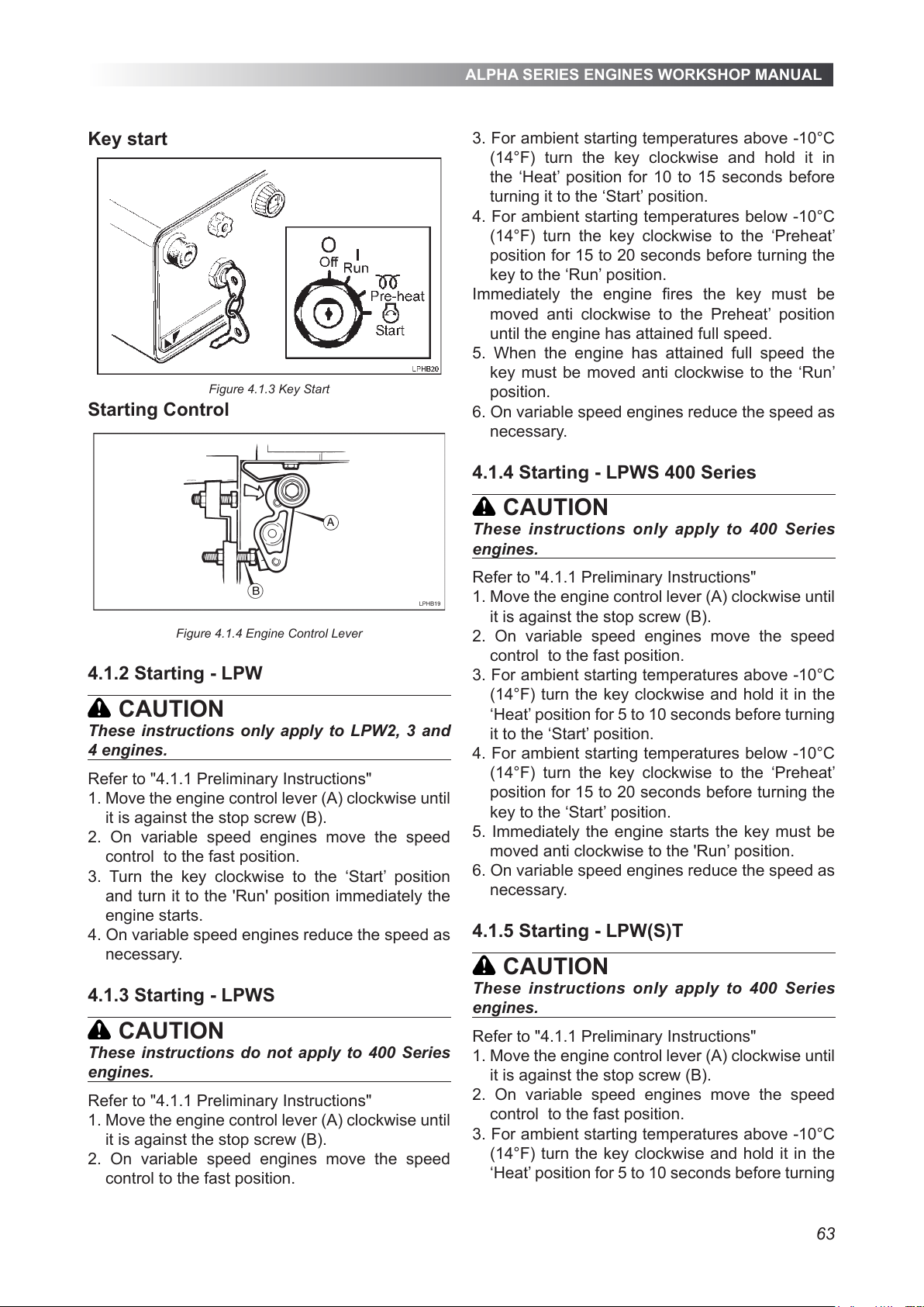
ALPHA SERIES ENGINES WORKSHOP MANUAL
63
Key start
Figure 4.1.3 Key Start
Starting Control
Figure 4.1.4 Engine Control Lever
4.1.2 Starting - LPW
CAUTION
These instructions only apply to LPW2, 3 and
4 engines.
Refer to "4.1.1 Preliminary Instructions"
1. Move the engine control lever (A) clockwise until
it is against the stop screw (B).
2. On variable speed engines move the speed
control to the fast position.
3. Turn the key clockwise to the ‘Start’ position
and turn it to the 'Run' position immediately the
engine starts.
4. On variable speed engines reduce the speed as
necessary.
4.1.3 Starting - LPWS
CAUTION
These instructions do not apply to 400 Series
engines.
Refer to "4.1.1 Preliminary Instructions"
1. Move the engine control lever (A) clockwise until
it is against the stop screw (B).
2. On variable speed engines move the speed
control to the fast position.
3. For ambient starting temperatures above -10°C
(14°F) turn the key clockwise and hold it in
the ‘Heat’ position for 10 to 15 seconds before
turning it to the ‘Start’ position.
4. For ambient starting temperatures below -10°C
(14°F) turn the key clockwise to the ‘Preheat’
position for 15 to 20 seconds before turning the
key to the ‘Run’ position.
Immediately the engine res the key must be
moved anti clockwise to the Preheat’ position
until the engine has attained full speed.
5. When the engine has attained full speed the
key must be moved anti clockwise to the ‘Run’
position.
6. On variable speed engines reduce the speed as
necessary.
4.1.4 Starting - LPWS 400 Series
CAUTION
These instructions only apply to 400 Series
engines.
Refer to "4.1.1 Preliminary Instructions"
1. Move the engine control lever (A) clockwise until
it is against the stop screw (B).
2. On variable speed engines move the speed
control to the fast position.
3. For ambient starting temperatures above -10°C
(14°F) turn the key clockwise and hold it in the
‘Heat’ position for 5 to 10 seconds before turning
it to the ‘Start’ position.
4. For ambient starting temperatures below -10°C
(14°F) turn the key clockwise to the ‘Preheat’
position for 15 to 20 seconds before turning the
key to the ‘Start’ position.
5. Immediately the engine starts the key must be
moved anti clockwise to the 'Run’ position.
6. On variable speed engines reduce the speed as
necessary.
4.1.5 Starting - LPW(S)T
CAUTION
These instructions only apply to 400 Series
engines.
Refer to "4.1.1 Preliminary Instructions"
1. Move the engine control lever (A) clockwise until
it is against the stop screw (B).
2. On variable speed engines move the speed
control to the fast position.
3. For ambient starting temperatures above -10°C
(14°F) turn the key clockwise and hold it in the
‘Heat’ position for 5 to 10 seconds before turning
All manuals and user guides at all-guides.com
Page 64
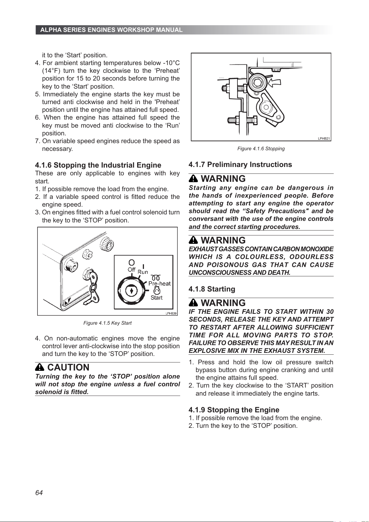
ALPHA SERIES ENGINES WORKSHOP MANUAL
64
it to the ‘Start’ position.
4. For ambient starting temperatures below -10°C
(14°F) turn the key clockwise to the ‘Preheat’
position for 15 to 20 seconds before turning the
key to the ‘Start’ position.
5. Immediately the engine starts the key must be
turned anti clockwise and held in the 'Preheat’
position until the engine has attained full speed.
6. When the engine has attained full speed the
key must be moved anti clockwise to the ‘Run’
position.
7. On variable speed engines reduce the speed as
necessary.
4.1.6 Stopping the Industrial Engine
These are only applicable to engines with key
start.
1. If possible remove the load from the engine.
2. If a variable speed control is tted reduce the
engine speed.
3. On engines tted with a fuel control solenoid turn
the key to the ‘STOP’ position.
Figure 4.1.5 Key Start
4. On non-automatic engines move the engine
control lever anti-clockwise into the stop position
and turn the key to the ‘STOP’ position.
CAUTION
Turning the key to the ‘STOP’ position alone
will not stop the engine unless a fuel control
solenoid is tted.
Figure 4.1.6 Stopping
4.1.7 Preliminary Instructions
WARNING
Starting any engine can be dangerous in
the hands of inexperienced people. Before
attempting to start any engine the operator
should read the “Safety Precautions" and be
conversant with the use of the engine controls
and the correct starting procedures.
WARNING
EXHAUST GASSES CONTAIN CARBON MONOXIDE
WHICH IS A COLOURLES S, ODOURLESS
AND POISONOUS GAS THAT CAN CAUSE
UNCONSCIOUSNESS AND DEATH.
4.1.8 Starting
WARNING
IF THE ENGINE FAILS TO START WITHIN 30
SECONDS, RELEASE THE KEY AND ATTEMPT
TO RESTART AFTER ALLOWING SUFFICIENT
TIME FOR ALL MOVING PARTS TO STOP.
FAILURE TO OBSERVE THIS MAY RESULT IN AN
EXPLOSIVE MIX IN THE EXHAUST SYSTEM.
1. Press and hold the low oil pressure switch
bypass button during engine cranking and until
the engine attains full speed.
2. Turn the key clockwise to the ‘START’ position
and release it immediately the engine tarts.
4.1.9 Stopping the Engine
1. If possible remove the load from the engine.
2. Turn the key to the ‘STOP’ position.
All manuals and user guides at all-guides.com
Page 65
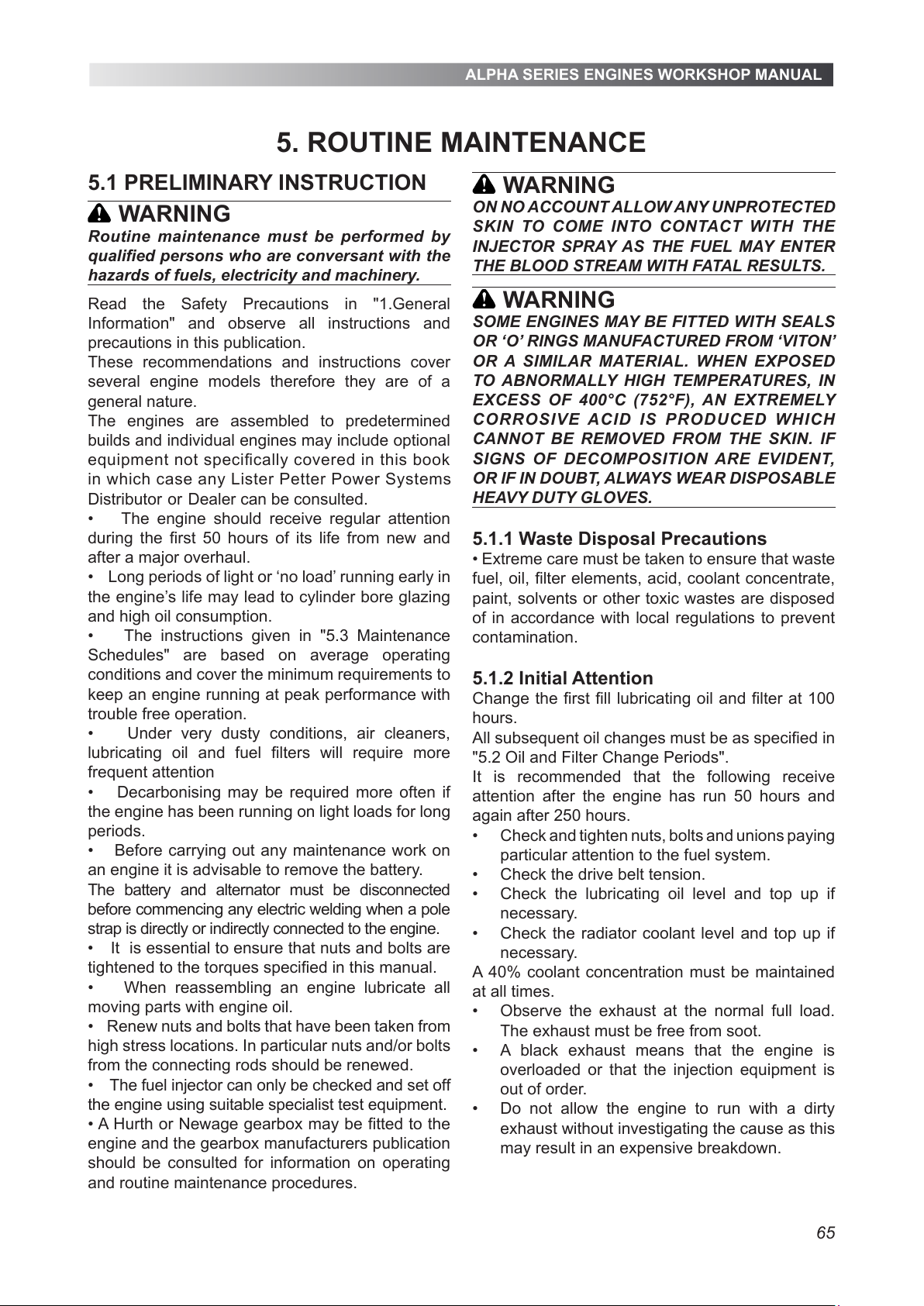
ALPHA SERIES ENGINES WORKSHOP MANUAL
65
5.1 PRELIMINARY INSTRUCTION
WARNING
Routine maintenance must be performed by
qualified persons who are conversant with the
hazards of fuels, electricity and machinery.
Read the Safety Precautions in "1.General
Information" and observe all instructions and
precautions in this publication.
These recommendations and instructions cover
several engine models therefore they are of a
general nature.
The engines are assembled to predetermined
builds and individual engines may include optional
equipment not specifically covered in this book
in which case any Lister Petter Power Systems
Distributor or Dealer can be consulted.
• The engine should receive regular attention
during the first 50 hours of its life from new and
after a major overhaul.
• Long periods of light or ‘no load’ running early in
the engine’s life may lead to cylinder bore glazing
and high oil consumption.
• The instructions given in "5.3 Maintenance
Schedules" are based on average operating
conditions and cover the minimum requirements to
keep an engine running at peak performance with
trouble free operation.
• Under very dusty conditions, air cleaners,
lubricating oil and fuel filters will require more
frequent attention
• Decarbonising may be required more often if
the engine has been running on light loads for long
periods.
• Before carrying out any maintenance work on
an engine it is advisable to remove the battery.
The battery and alternator must be disconnected
before commencing any electric welding when a pole
strap is directly or indirectly connected to the engine.
• It
is essential to ensure that nuts and bolts are
tightened to the torques specified in this manual.
• When reassembling an engine lubricate all
moving parts with engine oil.
• Renew nuts and bolts that have been taken from
high stress locations. In particular nuts and/or bolts
from the connecting rods should be renewed.
• The fuel injector can only be checked and set off
the engine using suitable specialist test equipment.
• A Hurth or Newage gearbox may be fitted to the
engine and the gearbox manufacturers publication
should be consulted for information on operating
and routine maintenance procedures.
WARNING
ON NO ACCOUNT ALLOW ANY UNPROTECTED
SKIN TO COME INTO CONTACT WITH THE
INJECTOR SPRAY AS THE FUEL MAY ENTER
THE BLOOD STREAM WITH FATAL RESULTS.
WARNING
SOME ENGINES MAY BE FITTED WITH SEALS
OR ‘O’ RINGS MANUFACTURED FROM ‘VITON’
OR A SIMILAR MATERIAL. WHEN EXPOSED
TO ABNORMALLY HIGH TEMPERATURES, IN
EXCESS OF 400°C (752°F), AN EXTREMELY
CORROSIVE ACID IS PR ODUCED WHICH
CANNOT BE REMOVED FROM THE SKIN. IF
SIGNS OF DECOMPOSITION ARE EVIDENT,
OR IF IN DOUBT, ALWAYS WEAR DISPOSABLE
HEAVY DUTY GLOVES.
5.1.1 Waste Disposal Precautions
• Extreme care must be taken to ensure that waste
fuel, oil, filter elements, acid, coolant concentrate,
paint, solvents or other toxic wastes are disposed
of in accordance with local regulations to prevent
contamination.
5.1.2 Initial Attention
Change the first fill lubricating oil and filter at 100
hours.
All subsequent oil changes must be as specified in
"5.2 Oil and Filter Change Periods".
It is recommended that the following receive
attention after the engine has run 50 hours and
again after 250 hours.
Check and tighten nuts, bolts and unions paying •
particular attention to the fuel system.
Check the drive belt tension.•
Check the lubricating oil level and top up if •
necessary.
Check the radiator
coolant level and top up if •
necessary.
A 40% coolant concentration must be maintained
at all times.
Observe the exhaust at the normal full load. •
The exhaust must be free from soot.
A black exhaust means that the engine is •
overloaded or that the injection equipment is
out of order.
Do not allow the engine to run with a dirty •
exhaust without investigating the cause as this
may result in an expensive breakdown.
5. ROUTINE MAINTENANCE
All manuals and user guides at all-guides.com
Page 66
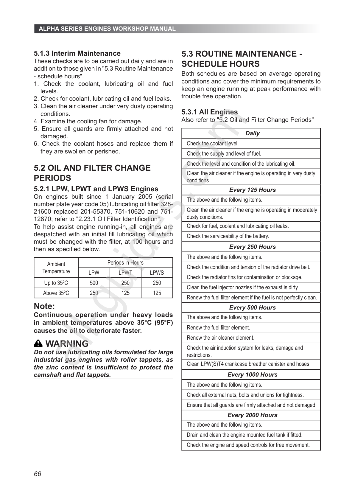
ALPHA SERIES ENGINES WORKSHOP MANUAL
66
5.1.3 Interim Maintenance
These checks are to be carried out daily and are in
addition to those given in "5.3 Routine Maintenance
- schedule hours".
1. Check the coolant, lubricating oil and fuel
levels.
2. Check for coolant, lubricating oil and fuel leaks.
3. Clean the air cleaner under very dusty operating
conditions.
4. Examine the cooling fan for damage.
5. Ensure all guards are rmly attached and not
damaged.
6. Check the coolant hoses and replace them if
they are swollen or perished.
5.2 OIL AND FILTER CHANGE
PERIODS
5.2.1 LPW, LPWT and LPWS Engines
On engines built since 1 January 2005 (serial
number plate year code 05) lubricating oil lter 328-
21600 replaced 201-55370, 751-10620 and 751-
12870; refer to "2.23.1 Oil Filter Identication".
To help assist engine running-in, all engines are
despatched with an initial ll lubricating oil which
must be changed with the lter, at 100 hours and
then as specied below.
Ambient
Temperature
Periods in Hours
LPW LPWT LPWS
Up to 35ºC 500 250 250
Above 35ºC 250 125 125
Note:
Continuous operation under heavy loads
in ambient temperatures above 35°C (95°F)
causes the oil to deteriorate faster.
WARNING
Do not use lubricating oils formulated for large
industrial gas engines with roller tappets, as
the zinc content is insufcient to protect the
5.3 ROUTINE MAINTENANCE -
SCHEDULE HOURS
Both schedules are based on average operating
conditions and cover the minimum requirements to
keep an engine running at peak performance with
trouble free operation.
5.3.1 All Engines
Also refer to "5.2 Oil and Filter Change Periods"
Daily
Check the coolant level.
Check the supply and level of fuel.
Check the level and condition of the lubricating oil.
Clean the air cleaner if the engine is operating in very dusty
conditions.
Every 125 Hours
The above and the following items.
Clean the air cleaner if the engine is operating in moderately
dusty conditions.
Check for fuel, coolant and lubricating oil leaks.
Check the serviceability of the battery.
Every 250 Hours
The above and the following items.
Check the condition and tension of the radiator drive belt.
Check the radiator ns for contamination or blockage.
Clean the fuel injector nozzles if the exhaust is dirty.
Renew the fuel lter element if the fuel is not perfectly clean.
Every 500 Hours
The above and the following items.
Renew the fuel lter element.
Renew the air cleaner element.
Check the air induction system for leaks, damage and
restrictions.
Clean LPW(S)T4 crankcase breather canister and hoses.
Every 1000 Hours
The above and the following items.
Check all external nuts, bolts and unions for tightness.
Ensure that all guards are rmly attached and not damaged.
Every 2000 Hours
The above and the following items.
Drain and clean the engine mounted fuel tank if tted.
Check the engine and speed controls for free movement.
All manuals and user guides at all-guides.com
all-guides.com
Page 67
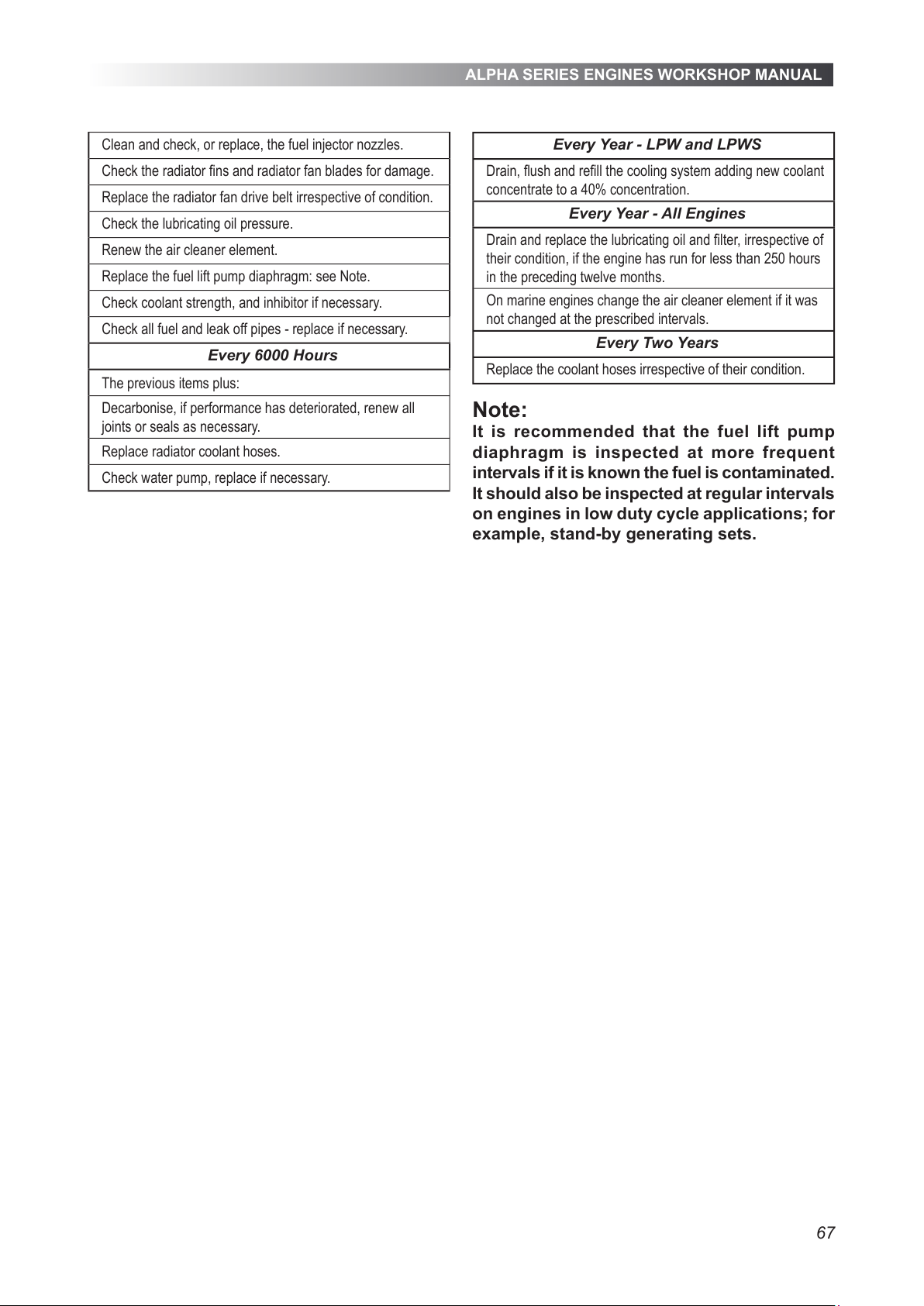
ALPHA SERIES ENGINES WORKSHOP MANUAL
67
Clean and check, or replace, the fuel injector nozzles.
Check the radiator ns and radiator fan blades for damage.
Replace the radiator fan drive belt irrespective of condition.
Check the lubricating oil pressure.
Renew the air cleaner element.
Replace the fuel lift pump diaphragm: see Note.
Check coolant strength, and inhibitor if necessary.
Check all fuel and leak off pipes - replace if necessary.
Every 6000 Hours
The previous items plus:
Decarbonise, if performance has deteriorated, renew all
joints or seals as necessary.
Replace radiator coolant hoses.
Check water pump, replace if necessary.
Every Year - LPW and LPWS
Drain, ush and rell the cooling system adding new coolant
concentrate to a 40% concentration.
Every Year - All Engines
Drain and replace the lubricating oil and lter, irrespective of
their condition, if the engine has run for less than 250 hours
in the preceding twelve months.
On marine engines change the air cleaner element if it was
not changed at the prescribed intervals.
Every Two Years
Replace the coolant hoses irrespective of their condition.
Note:
It is recommended that the fuel lift pump
diaphragm is inspected at more frequent
intervals if it is known the fuel is contaminated.
It should also be inspected at regular intervals
on engines in low duty cycle applications; for
example, stand-by generating sets.
All manuals and user guides at all-guides.com
Page 68
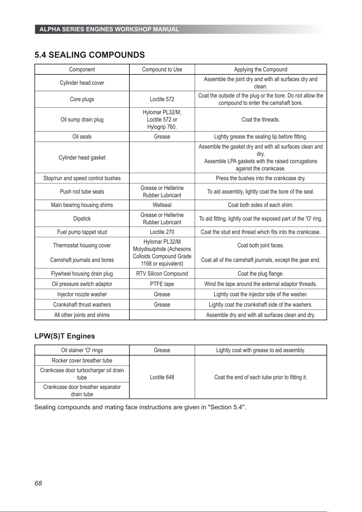
ALPHA SERIES ENGINES WORKSHOP MANUAL
68
5.4 SEALING COMPOUNDS
Component Compound to Use Applying the Compound
Cylinder head cover
Assemble the joint dry and with all surfaces dry and
clean.
Core plugs Loctite 572
Coat the outside of the plug or the bore. Do not allow the
compound to enter the camshaft bore.
Oil sump drain plug
Hylomar PL32/M,
Loctite 572 or
Hylogrip 760.
Coat the threads.
Oil seals Grease Lightly grease the sealing lip before tting.
Cylinder head gasket
Assemble the gasket dry and with all surfaces clean and
dry.
Assemble LPA gaskets with the raised corrugations
against the crankcase.
Stop/run and speed control bushes Press the bushes into the crankcase dry.
Push rod tube seals
Grease or Hellerine
Rubber Lubricant
To aid assembly, lightly coat the bore of the seal.
Main bearing housing shims Wellseal Coat both sides of each shim.
Dipstick
Grease or Hellerine
Rubber Lubricant
To aid tting, lightly coat the exposed part of the 'O' ring.
Fuel pump tappet stud Loctite 270 Coat the stud end thread which ts into the crankcase.
Thermostat housing cover
Camshaft journals and bores
Hylomar PL32/M
Molydisulphide (Achesons
Colloids Compound Grade
1168 or equivalent)
Coat both joint faces.
Coat all of the camshaft journals, except the gear end.
Flywheel housing drain plug RTV Silicon Compound Coat the plug ange.
Oil pressure switch adaptor PTFE tape Wind the tape around the external adaptor threads.
Injector nozzle washer Grease Lightly coat the injector side of the washer.
Crankshaft thrust washers Grease Lightly coat the crankshaft side of the washers.
All other joints and shims Assemble dry and with all surfaces clean and dry.
LPW(S)T Engines
Oil stainer 'O' rings Grease Lightly coat with grease to aid assembly.
Rocker cover breather tube
Loctite 648 Coat the end of each tube prior to tting it.
Crankcase door turbocharger oil drain
tube
Crankcase door breather separator
drain tube
Sealing compounds and mating face instructions are given in "Section 5.4".
All manuals and user guides at all-guides.com
Page 69
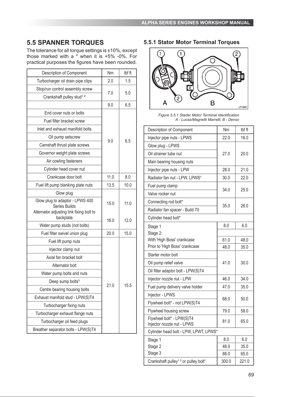
ALPHA SERIES ENGINES WORKSHOP MANUAL
69
5.5 SPANNER TORQUES
The tolerance for all torque settings is ±10%, except
those marked with a * when it is +5% -0%. For
practical purposes the gures have been rounded.
Description of Component Nm lbf ft
Turbocharger oil drain pipe clips 2.0 1.5
Stop/run control assembly screw
7.0 5.0
Crankshaft pulley stud¹ ²
9.0 6.5
End cover nuts or bolts
9.0 6.5
Fuel lter bracket screw
Inlet and exhaust manifold bolts
Oil pump setscrew
Camshaft thrust plate screws
Governor weight plate screws
Air cowling fasteners
Cylinder head cover nut
Crankcase door bolt 11.0 8.0
Fuel lift pump blanking plate nuts 13.5 10.0
Glow plug
15.0
16.0
11.0
12.0
Glow plug to adaptor - LPWS 400
Series Builds
Alternator adjusting link xing bolt to
backplate
Water pump studs (not bolts)
Fuel lter swivel union plug 20.0 15.0
Fuel lift pump nuts
21.0 15.5
Injector clamp nut
Axial fan bracket bolt
Alternator bolt
Water pump bolts and nuts
Deep sump bolts³
Centre bearing housing bolts
Exhaust manifold stud - LPW(S)T4
Turbocharger xing nuts
Turbocharger exhaust ange nuts
Turbocharger oil feed plugs
Breather separator bolts - LPW(S)T4
5.5.1 Stator Motor Terminal Torques
Figure 5.5.1 Starter Motor Terminal Identication
A - Lucas/Magnetti Marrelli; B - Denso
Description of Component Nm lbf ft
Injector pipe nuts - LPWS 22.0 16.0
Glow plug - LPWS
27.0 20.0Oil strainer tube nut
Main bearing housing nuts
Injector pipe nuts - LPW 28.0 21.0
Radiator fan nut - LPW, LPWS¹ 30.0 22.0
Fuel pump clamp
34.0 25.0
Valve rocker nut
Connecting rod bolt*
35.0 26.0
Radiator fan spacer - Build 70
Cylinder head bolt*
Stage 1
Stage 2:
With 'High Boss' crankcase
Prior to 'High Boss' crankcase
8.0 6.0
61.0 48.0
48.0 35.0
Starter motor bolt
41.0 30.0Oil pump relief valve
Oil lter adaptor bolt - LPW(S)T4
Injector nozzle nut - LPW 46.0 34.0
Fuel pump delivery valve holder 47.0 35.0
Injector - LPWS
68.0 50.0
Flywheel bolt* - not LPW(S)T4
Flywheel housing screw 79.0 58.0
Flywheel bolt* - LPW(S)T4
Injector nozzle nut - LPWS
81.0 65.0
Cylinder head bolt - LPW, LPWT, LPWS*
Stage 1
Stage 2
Stage 3
8.0 6.0
48.0 35.0
88.0 65.0
Crankshaft pulley¹ ² or pulley bolt¹ 300.0 221.0
All manuals and user guides at all-guides.com
Page 70
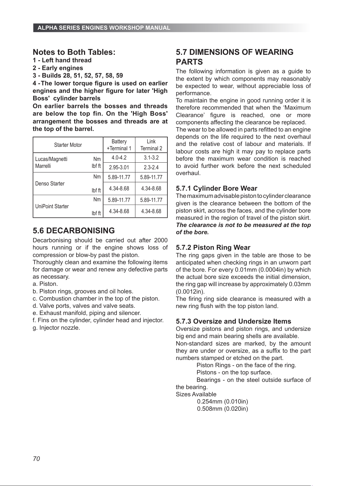
ALPHA SERIES ENGINES WORKSHOP MANUAL
70
Notes to Both Tables:
1 - Left hand thread
2 - Early engines
3 - Builds 28, 51, 52, 57, 58, 59
4 - The lower torque gure is used on earlier
engines and the higher gure for later 'High
Boss' cylinder barrels
On earlier barrels the bosses and threads
are below the top fin. On the 'High Boss'
arrangement the bosses and threads are at
the top of the barrel.
Starter Motor
Battery
+Terminal 1
Link
Terminal 2
Lucas/Magnetti Nm
Marrelli lbf ft
4.0-4.2 3.1-3.2
2.95-3.01 2.3-2.4
Nm
Denso Starter
lbf ft
5.89-11.77 5.89-11.77
4.34-8.68 4.34-8.68
Nm
UniPoint Starter
lbf ft
5.89-11.77 5.89-11.77
4.34-8.68 4.34-8.68
5.6 DECARBONISING
Decarbonising should be carried out after 2000
hours running or if the engine shows loss of
compression or blow-by past the piston.
Thoroughly clean and examine the following items
for damage or wear and renew any defective parts
as necessary.
a. Piston.
b. Piston rings, grooves and oil holes.
c. Combustion chamber in the top of the piston.
d. Valve ports, valves and valve seats.
e. Exhaust manifold, piping and silencer.
f. Fins on the cylinder, cylinder head and injector.
g. Injector nozzle.
5.7 DIMENSIONS OF WEARING
PARTS
The following information is given as a guide to
the extent by which components may reasonably
be expected to wear, without appreciable loss of
performance.
To maintain the engine in good running order it is
therefore recommended that when the ‘Maximum
Clearance’ gure is reached, one or more
components affecting the clearance be replaced.
The wear to be allowed in parts retted to an engine
depends on the life required to the next overhaul
and the relative cost of labour and materials. If
labour costs are high it may pay to replace parts
before the maximum wear condition is reached
to avoid further work before the next scheduled
overhaul.
5.7.1 Cylinder Bore Wear
The maximum advisable piston to cylinder clearance
given is the clearance between the bottom of the
piston skirt, across the faces, and the cylinder bore
measured in the region of travel of the piston skirt.
The clearance is not to be measured at the top
of the bore.
5.7.2 Piston Ring Wear
The ring gaps given in the table are those to be
anticipated when checking rings in an unworn part
of the bore. For every 0.01mm (0.0004in) by which
the actual bore size exceeds the initial dimension,
the ring gap will increase by approximately 0.03mm
(0.0012in).
The ring ring side clearance is measured with a
new ring ush with the top piston land.
5.7.3 Oversize and Undersize Items
Oversize pistons and piston rings, and undersize
big end and main bearing shells are available.
Non-standard sizes are marked, by the amount
they are under or oversize, as a sufx to the part
numbers stamped or etched on the part.
Piston Rings - on the face of the ring.
Pistons - on the top surface.
Bearings - on the steel outside surface of
the bearing.
Sizes Available
0.254mm (0.010in)
0.508mm (0.020in)
All manuals and user guides at all-guides.com
Page 71
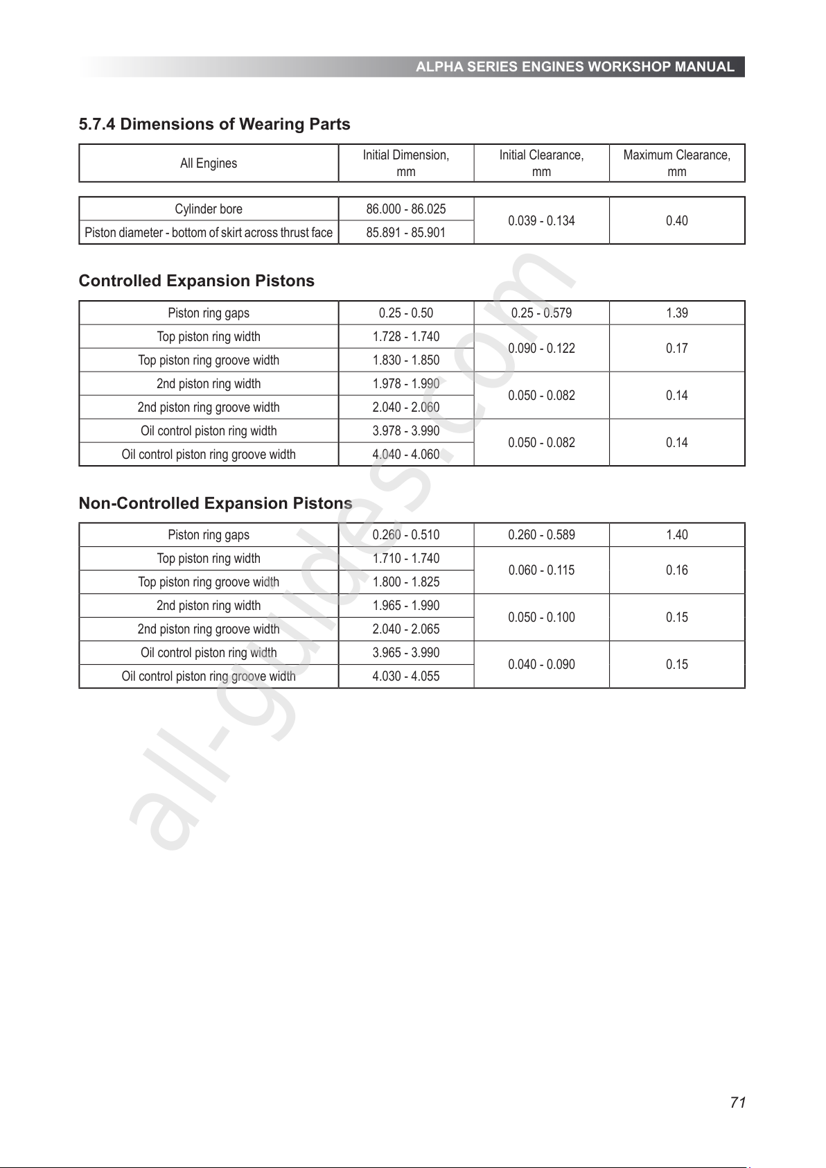
ALPHA SERIES ENGINES WORKSHOP MANUAL
71
5.7.4 Dimensions of Wearing Parts
All Engines
Initial Dimension,
mm
Initial Clearance,
mm
Maximum Clearance,
mm
Cylinder bore 86.000 - 86.025
0.039 - 0.134 0.40
Piston diameter - bottom of skirt across thrust face 85.891 - 85.901
Controlled Expansion Pistons
Piston ring gaps 0.25 - 0.50 0.25 - 0.579 1.39
Top piston ring width 1.728 - 1.740
0.090 - 0.122 0.17
Top piston ring groove width 1.830 - 1.850
2nd piston ring width 1.978 - 1.990
0.050 - 0.082 0.14
2nd piston ring groove width 2.040 - 2.060
Oil control piston ring width 3.978 - 3.990
0.050 - 0.082 0.14
Oil control piston ring groove width 4.040 - 4.060
Non-Controlled Expansion Pistons
Piston ring gaps 0.260 - 0.510 0.260 - 0.589 1.40
Top piston ring width 1.710 - 1.740
0.060 - 0.115 0.16
Top piston ring groove width 1.800 - 1.825
2nd piston ring width 1.965 - 1.990
0.050 - 0.100 0.15
2nd piston ring groove width 2.040 - 2.065
Oil control piston ring width 3.965 - 3.990
0.040 - 0.090 0.15
Oil control piston ring groove width 4.030 - 4.055
All manuals and user guides at all-guides.com
all-guides.com
Page 72
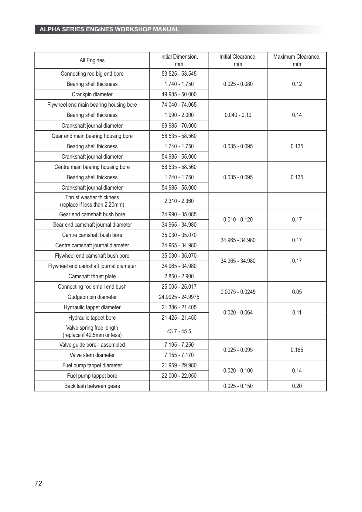
ALPHA SERIES ENGINES WORKSHOP MANUAL
72
All Engines
Initial Dimension,
mm
Initial Clearance,
mm
Maximum Clearance,
mm
Connecting rod big end bore 53.525 - 53.545
0.025 - 0.080 0.12Bearing shell thickness 1.740 - 1.750
Crankpin diameter 49.985 - 50.000
Flywheel end main bearing housing bore 74.040 - 74.065
0.040 - 0.10 0.14Bearing shell thickness 1.990 - 2.000
Crankshaft journal diameter 69.985 - 70.000
Gear end main bearing housing bore 58.535 - 58.560
0.035 - 0.095 0.135Bearing shell thickness 1.740 - 1.750
Crankshaft journal diameter 54.985 - 55.000
Centre main bearing housing bore 58.535 - 58.560
0.035 - 0.095 0.135Bearing shell thickness 1.740 - 1.750
Crankshaft journal diameter 54.985 - 55.000
Thrust washer thickness
(replace if less than 2.20mm)
2.310 - 2.360
Gear end camshaft bush bore 34.990 - 35.085
0.010 - 0.120 0.17
Gear end camshaft journal diameter 34.965 - 34.980
Centre camshaft bush bore 35.030 - 35.070
34.965 - 34.980 0.17
Centre camshaft journal diameter 34.965 - 34.980
Flywheel end camshaft bush bore 35.030 - 35.070
34.965 - 34.980 0.17
Flywheel end camshaft journal diameter 34.965 - 34.980
Camshaft thrust plate 2.850 - 2.900
Connecting rod small end bush 25.005 - 25.017
0.0075 - 0.0245 0.05
Gudgeon pin diameter 24.9925 - 24.9975
Hydraulic tappet diameter 21.386 - 21.405
0.020 - 0.064 0.11
Hydraulic tappet bore 21.425 - 21.450
Valve spring free length
(replace if 42.5mm or less)
43.7 - 45.5
Valve guide bore - assembled 7.195 - 7.250
0.025 - 0.095 0.165
Valve stem diameter 7.155 - 7.170
Fuel pump tappet diameter 21.959 - 29.980
0.020 - 0.100 0.14
Fuel pump tappet bore 22.000 - 22.050
Back lash between gears 0.025 - 0.150 0.20
All manuals and user guides at all-guides.com
Page 73
ALPHA SERIES ENGINES WORKSHOP MANUAL
73
5.8 LONG TERM STORAGE
5.8.1 Preparing the Engine for Storage
The following routine should be carried out when
it is known that the engine will not be required for
some months.
If the following procedure is not carried out the
engine should be run on full load for approximately
45 minutes once a month.
CAUTION
As a direct result of combustion the lubricating
oil may contain harmful acids and therefore
it should not be left in the sump if it is known
engine will not be used for extended periods.
a. Replace the fuel in the tank with a small supply
of suitable inhibition uid.
b. Drain the lubricating oil from the sump and rell
with new oil.
c. Run the engine for a period to circulate the oil
through the system and to ensure the inhibition
uid is passed through the fuel pumps and
injectors.
d. Stop the engine, drain the cooling system and
drain the lubricating oil from the sump.
The crankshaft should NOT be turned until the
engine is again required for service.
The inhibition uid should be left in the fuel
system.
e. Seal all openings on the engine with tape.
f. Remove the batteries and store them fully charged
after coating the terminals with petroleum jelly.
g. Grease all external bright metal parts and the
speed control linkage.
h. Tie labels on the engine clearly stating what
steps have been taken to inhibit the engine
during storage.
5.8.2 Returning the Engine to Service
Refer to the appropriate sections for the relevant
detailed instructions as necessary to complete this
work.
a. Remove the tie-on labels and all the protective
coverings from openings and apertures.
b. Check the drive belt for deterioration and correct
tension.
c. Check to ensure the drive belt pulley grooves
are corrosion free.
d. Fill the fuel tank.
e. Rell the cooling system, adding new coolant
concentrate to a 50% concentration.
f. Rell the lubricating oil sump with new oil of the
correct specication and viscosity.
g. Remove the batteries from store. If they are still
fully charged reconnect them to the engine.
Coat the terminals with petroleum jelly.
h. Start the engine and check for coolant, fuel and
oil leaks before applying load.
All manuals and user guides at all-guides.com
Page 74
ALPHA SERIES ENGINES WORKSHOP MANUAL
74
6. TROUBLESHOOTING
6.1 PRELIMINARY INFORMATION
Troubleshooting mechanical engine problems
can be difficult. This section lists possible engine
problems that could be encountered with possible
causes and corrections. The information given is of
a general nature as it covers the basic engine and
your particular application may be different.
Electrical wiring diagrams can be found in 'Section
08'.
If you are in any doubt, contact your local Lister
Petter Power Systems distributor.
Before starting any dismantling procedure the
following should be considered:
a. Do you know and understand the engine and all
the related systems?
b. Do you have sufficient electrical and mechanical
knowledge and skills to understand the
symptoms?
c. Do you have suitable electrical diagnostic
equipment available?
d. Do you have, or access to, the necessary
Lister Petter spare parts before you commence
dismantling.
6.2 METHOD OF
TROUBLESHOOTING
1. Diagnose the problem by eliminating the easiest
things first.
2. Before starting to remove or dismantle any
components double check your observations.
3. During dismantling keep all cylinder related items
together. This will ensure they are refitted in the
original orientation.
4. When electrical troubleshooting always start at
the battery first.
All manuals and user guides at all-guides.com
Page 75
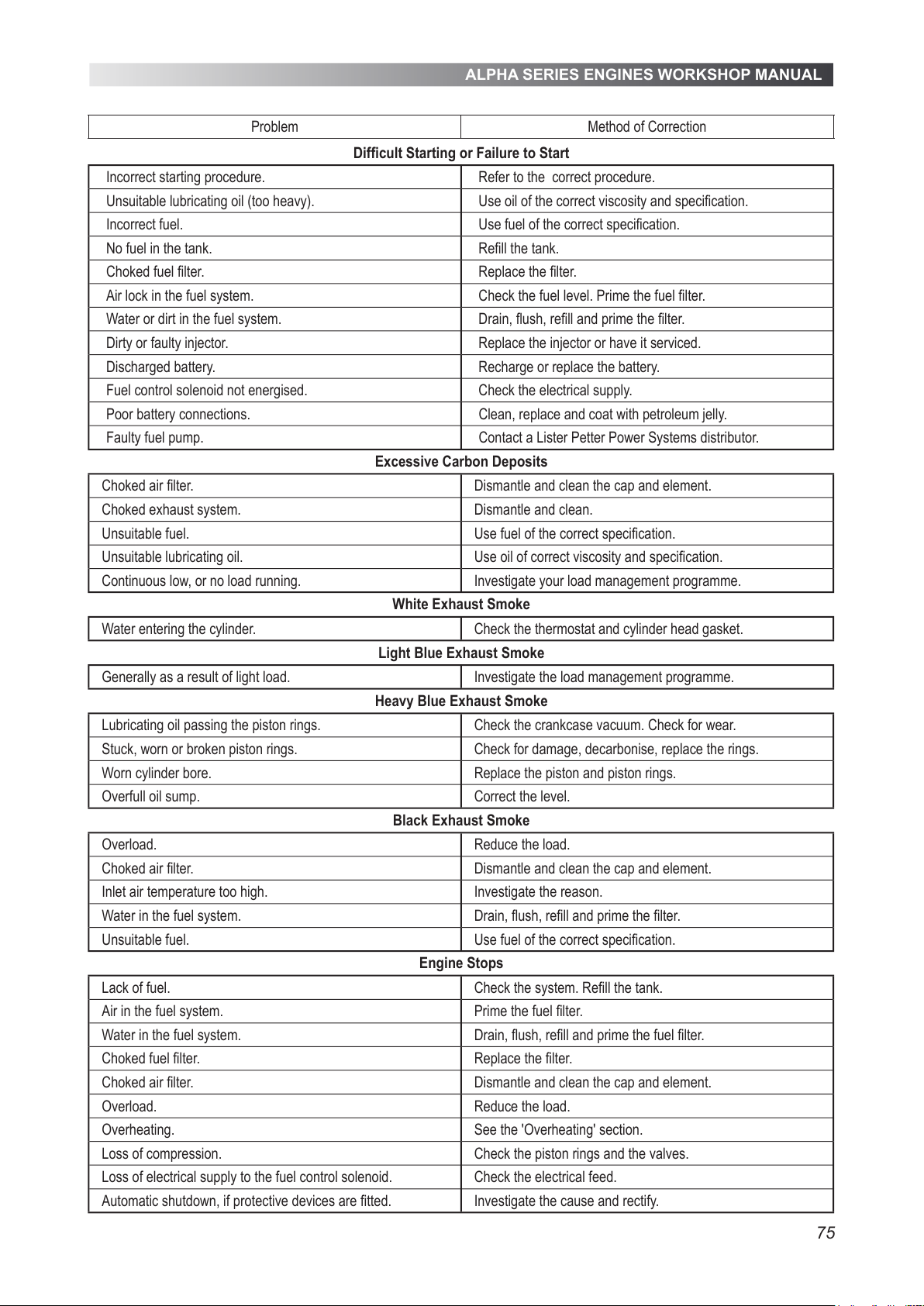
ALPHA SERIES ENGINES WORKSHOP MANUAL
75
Problem Method of Correction
Difficult Starting or Failure to Start
Incorrect starting procedure. Refer to the correct procedure.
Unsuitable lubricating oil (too heavy). Use oil of the correct viscosity and specification.
Incorrect fuel. Use fuel of the correct specification.
No fuel in the tank. Refill the tank.
Choked fuel filter. Replace the filter.
Air lock in the fuel system. Check the fuel level. Prime the fuel filter.
Water or dirt in the fuel system. Drain, flush, refill and prime the filter.
Dirty or faulty injector. Replace the injector or have it serviced.
Discharged battery. Recharge or replace the battery.
Fuel control solenoid not energised. Check the electrical supply.
Poor battery connections. Clean, replace and coat with petroleum jelly.
Faulty fuel pump. Contact a Lister Petter Power Systems distributor.
Excessive Carbon Deposits
Choked air filter. Dismantle and clean the cap and element.
Choked exhaust system. Dismantle and clean.
Unsuitable fuel. Use fuel of the correct specification.
Unsuitable lubricating oil. Use oil of correct viscosity and specification.
Continuous low, or no load running. Investigate your load management programme.
White Exhaust Smoke
Water entering the cylinder. Check the thermostat and cylinder head gasket.
Light Blue Exhaust Smoke
Generally as a result of light load. Investigate the load management programme.
Heavy Blue Exhaust Smoke
Lubricating oil passing the piston rings. Check the crankcase vacuum. Check for wear.
Stuck, worn or broken piston rings. Check for damage, decarbonise, replace the rings.
Worn cylinder bore. Replace the piston and piston rings.
Overfull oil sump. Correct the level.
Black Exhaust Smoke
Overload. Reduce the load.
Choked air filter. Dismantle and clean the cap and element.
Inlet air temperature too high. Investigate the reason.
Water in the fuel system. Drain, flush, refill and prime the filter.
Unsuitable fuel. Use fuel of the correct specification.
Engine Stops
Lack of fuel. Check the system. Refill the tank.
Air in the fuel system. Prime the fuel filter.
Water in the fuel system. Drain, flush, refill and prime the fuel filter.
Choked fuel filter. Replace the filter.
Choked air filter. Dismantle and clean the cap and element.
Overload. Reduce the load.
Overheating. See the 'Overheating' section.
Loss of compression. Check the piston rings and the valves.
Loss of electrical supply to the fuel control solenoid. Check the electrical feed.
Automatic shutdown, if protective devices are fitted. Investigate the cause and rectify.
All manuals and user guides at all-guides.com
Page 76
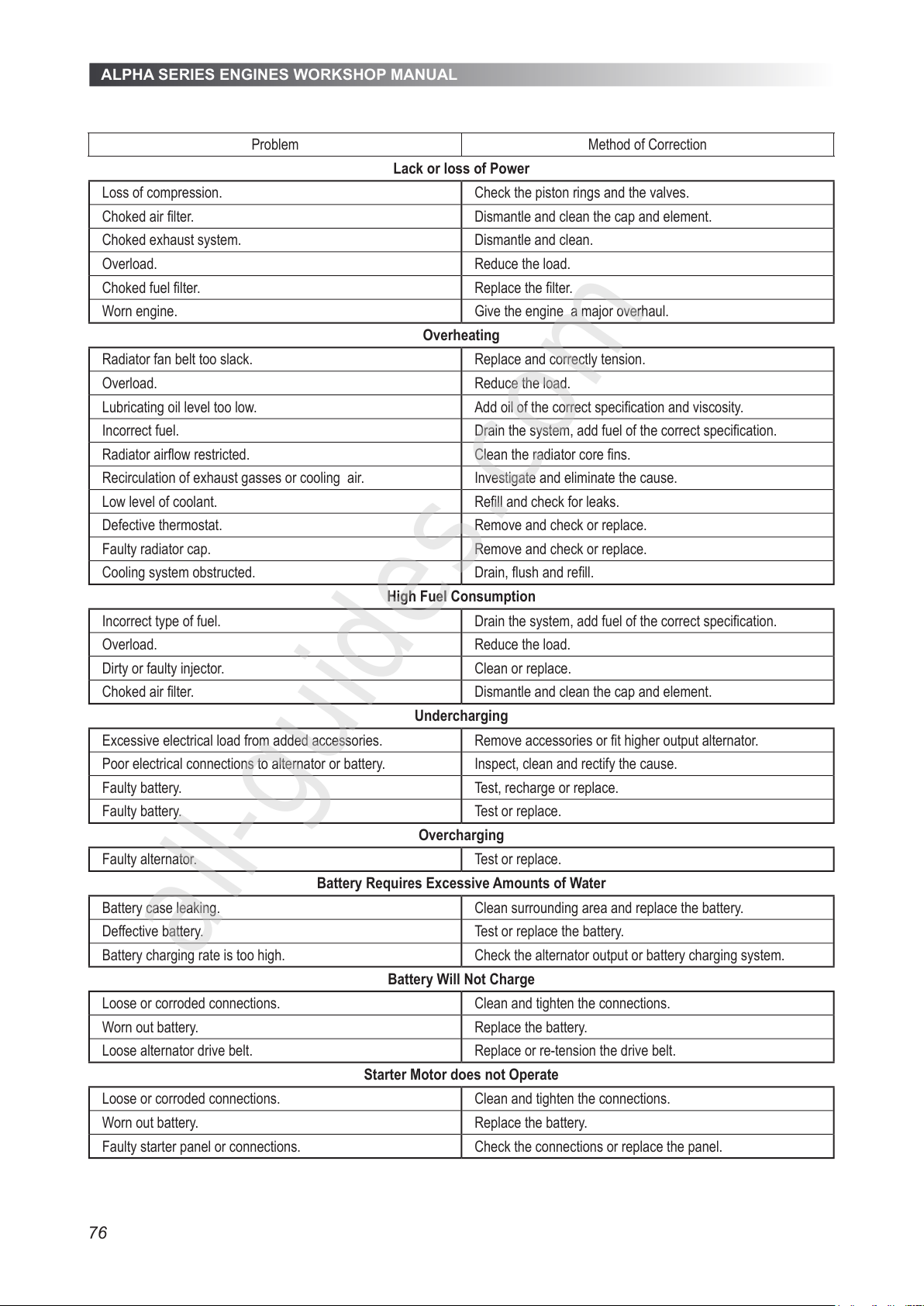
ALPHA SERIES ENGINES WORKSHOP MANUAL
76
Problem Method of Correction
Lack or loss of Power
Loss of compression. Check the piston rings and the valves.
Choked air lter. Dismantle and clean the cap and element.
Choked exhaust system. Dismantle and clean.
Overload. Reduce the load.
Choked fuel lter. Replace the lter.
Worn engine. Give the engine a major overhaul.
Overheating
Radiator fan belt too slack. Replace and correctly tension.
Overload. Reduce the load.
Lubricating oil level too low. Add oil of the correct specication and viscosity.
Incorrect fuel. Drain the system, add fuel of the correct specication.
Radiator airow restricted. Clean the radiator core ns.
Recirculation of exhaust gasses or cooling air. Investigate and eliminate the cause.
Low level of coolant. Rell and check for leaks.
Defective thermostat. Remove and check or replace.
Faulty radiator cap. Remove and check or replace.
Cooling system obstructed. Drain, ush and rell.
High Fuel Consumption
Incorrect type of fuel. Drain the system, add fuel of the correct specication.
Overload. Reduce the load.
Dirty or faulty injector. Clean or replace.
Choked air lter. Dismantle and clean the cap and element.
Undercharging
Excessive electrical load from added accessories. Remove accessories or t higher output alternator.
Poor electrical connections to alternator or battery. Inspect, clean and rectify the cause.
Faulty battery. Test, recharge or replace.
Faulty battery. Test or replace.
Overcharging
Faulty alternator. Test or replace.
Battery Requires Excessive Amounts of Water
Battery case leaking. Clean surrounding area and replace the battery.
Deffective battery. Test or replace the battery.
Battery charging rate is too high. Check the alternator output or battery charging system.
Battery Will Not Charge
Loose or corroded connections. Clean and tighten the connections.
Worn out battery. Replace the battery.
Loose alternator drive belt. Replace or re-tension the drive belt.
Starter Motor does not Operate
Loose or corroded connections. Clean and tighten the connections.
Worn out battery. Replace the battery.
Faulty starter panel or connections. Check the connections or replace the panel.
All manuals and user guides at all-guides.com
all-guides.com
Page 77
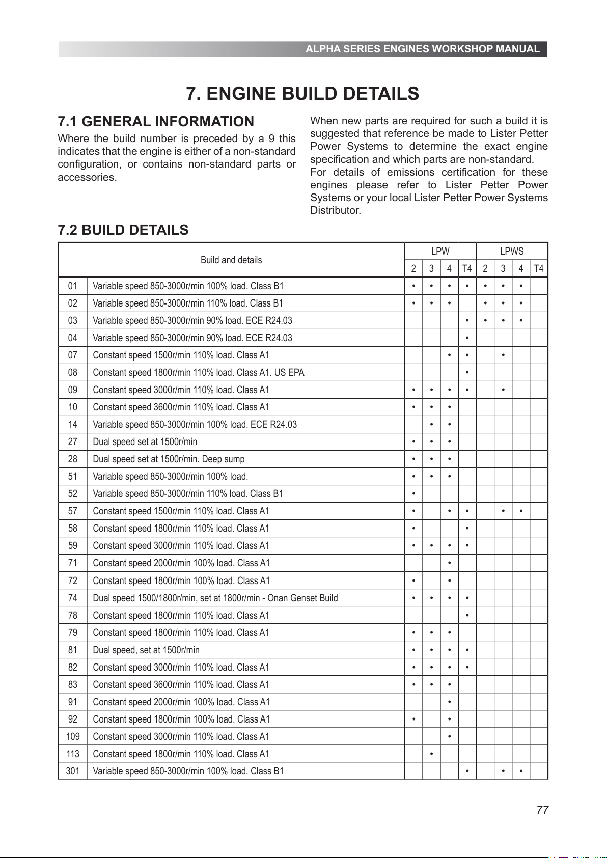
ALPHA SERIES ENGINES WORKSHOP MANUAL
77
7.1 GENERAL INFORMATION
Where the build number is preceded by a 9 this
indicates that the engine is either of a non-standard
configuration, or contains non-standard parts or
accessories.
7. ENGINE BUILD DETAILS
7.2 BUILD DETAILS
Build and details
LPW LPWS
2 3 4 T4 2 3 4 T4
01 Variable speed 850-3000r/min 100% load. Class B1 • • • • • • •
02 Variable speed 850-3000r/min 110% load. Class B1 • • • • • •
03 Variable speed 850-3000r/min 90% load. ECE R24.03 • • • •
04 Variable speed 850-3000r/min 90% load. ECE R24.03 •
07 Constant speed 1500r/min 110% load. Class A1 • • •
08 Constant speed 1800r/min 110% load. Class A1. US EPA •
09 Constant speed 3000r/min 110% load. Class A1 • • • • •
10 Constant speed 3600r/min 110% load. Class A1 • • •
14 Variable speed 850-3000r/min 100% load. ECE R24.03 • •
27 Dual speed set at 1500r/min • • •
28 Dual speed set at 1500r/min. Deep sump • • •
51 Variable speed 850-3000r/min 100% load. • • •
52 Variable speed 850-3000r/min 110% load. Class B1 •
57 Constant speed 1500r/min 110% load. Class A1 • • • • •
58 Constant speed 1800r/min 110% load. Class A1 • •
59 Constant speed 3000r/min 110% load. Class A1 • • • •
71 Constant speed 2000r/min 100% load. Class A1 •
72 Constant speed 1800r/min 100% load. Class A1 • •
74 Dual speed 1500/1800r/min, set at 1800r/min - Onan Genset Build • • • •
78 Constant speed 1800r/min 110% load. Class A1 •
79 Constant speed 1800r/min 110% load. Class A1 • • •
81 Dual speed, set at 1500r/min • • • •
82 Constant speed 3000r/min 110% load. Class A1 • • • •
83 Constant speed 3600r/min 110% load. Class A1 • • •
91 Constant speed 2000r/min 100% load. Class A1 •
92 Constant speed 1800r/min 100% load. Class A1 • •
109 Constant speed 3000r/min 110% load. Class A1 •
113 Constant speed 1800r/min 110% load. Class A1 •
301 Variable speed 850-3000r/min 100% load. Class B1 • • •
When new parts are required for such a build it is
suggested that reference be made to Lister Petter
Power Systems to determine the exact engine
specification and which parts are non-standard.
For details of emissions certification for these
engines please refer to Lister Petter Power
Systems or your local Lister Petter Power Systems
Distributor.
All manuals and user guides at all-guides.com
Page 78
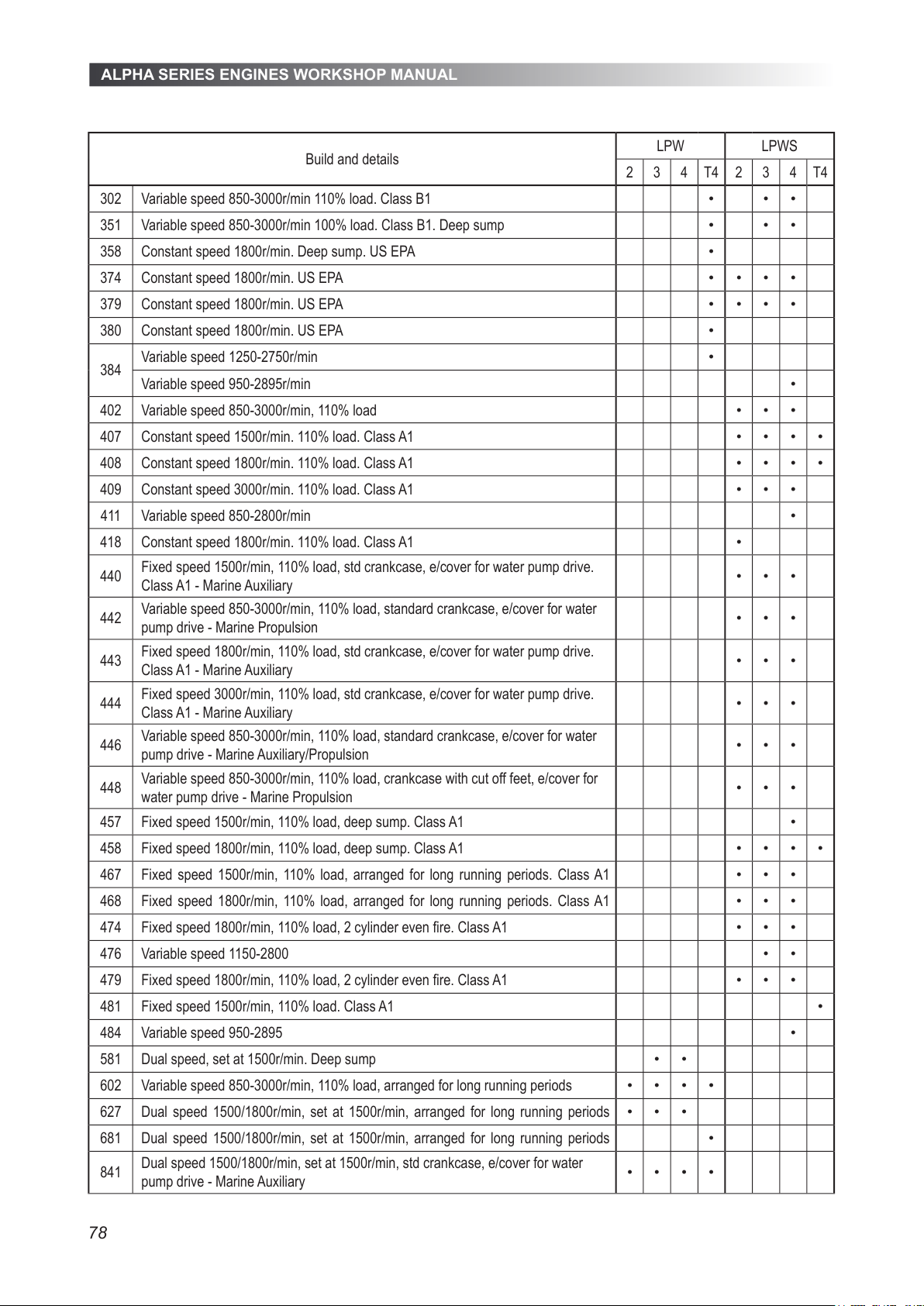
ALPHA SERIES ENGINES WORKSHOP MANUAL
78
Build and details
LPW LPWS
2 3 4 T4 2 3 4 T4
302 Variable speed 850-3000r/min 110% load. Class B1 • • •
351 Variable speed 850-3000r/min 100% load. Class B1. Deep sump • • •
358 Constant speed 1800r/min. Deep sump. US EPA •
374 Constant speed 1800r/min. US EPA • • • •
379 Constant speed 1800r/min. US EPA • • • •
380 Constant speed 1800r/min. US EPA •
384
Variable speed 1250-2750r/min •
Variable speed 950-2895r/min •
402 Variable speed 850-3000r/min, 110% load • • •
407 Constant speed 1500r/min. 110% load. Class A1 • • • •
408 Constant speed 1800r/min. 110% load. Class A1 • • • •
409 Constant speed 3000r/min. 110% load. Class A1 • • •
411 Variable speed 850-2800r/min •
418 Constant speed 1800r/min. 110% load. Class A1 •
440
Fixed speed 1500r/min, 110% load, std crankcase, e/cover for water pump drive.
Class A1 - Marine Auxiliary
• • •
442
Variable speed 850-3000r/min, 110% load, standard crankcase, e/cover for water
pump drive - Marine Propulsion
• • •
443
Fixed speed 1800r/min, 110% load, std crankcase, e/cover for water pump drive.
Class A1 - Marine Auxiliary
• • •
444
Fixed speed 3000r/min, 110% load, std crankcase, e/cover for water pump drive.
Class A1 - Marine Auxiliary
• • •
446
Variable speed 850-3000r/min, 110% load, standard crankcase, e/cover for water
pump drive - Marine Auxiliary/Propulsion
• • •
448
Variable speed 850-3000r/min, 110% load, crankcase with cut off feet, e/cover for
water pump drive - Marine Propulsion
• • •
457 Fixed speed 1500r/min, 110% load, deep sump. Class A1 •
458 Fixed speed 1800r/min, 110% load, deep sump. Class A1 • • • •
467 Fixed speed 1500r/min, 110% load, arranged for long running periods. Class A1 • • •
468 Fixed speed 1800r/min, 110% load, arranged for long running periods. Class A1 • • •
474 Fixed speed 1800r/min, 110% load, 2 cylinder even re. Class A1 • • •
476 Variable speed 1150-2800 • •
479 Fixed speed 1800r/min, 110% load, 2 cylinder even re. Class A1 • • •
481 Fixed speed 1500r/min, 110% load. Class A1 •
484 Variable speed 950-2895 •
581 Dual speed, set at 1500r/min. Deep sump • •
602 Variable speed 850-3000r/min, 110% load, arranged for long running periods • • • •
627 Dual speed 1500/1800r/min, set at 1500r/min, arranged for long running periods • • •
681 Dual speed 1500/1800r/min, set at 1500r/min, arranged for long running periods •
841
Dual speed 1500/1800r/min, set at 1500r/min, std crankcase, e/cover for water
pump drive - Marine Auxiliary
• • • •
All manuals and user guides at all-guides.com
Page 79
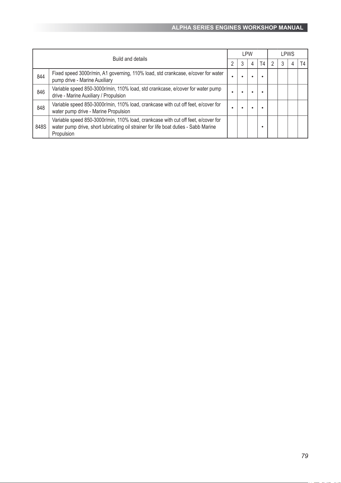
ALPHA SERIES ENGINES WORKSHOP MANUAL
79
Build and details
LPW LPWS
2 3 4 T4 2 3 4 T4
844
Fixed speed 3000r/min, A1 governing, 110% load, std crankcase, e/cover for water
pump drive - Marine Auxiliary
• • • •
846
Variable speed 850-3000r/min, 110% load, std crankcase, e/cover for water pump
drive - Marine Auxiliary / Propulsion
• • • •
848
Variable speed 850-3000r/min, 110% load, crankcase with cut off feet, e/cover for
water pump drive - Marine Propulsion
• • • •
848S
Variable speed 850-3000r/min, 110% load, crankcase with cut off feet, e/cover for
water pump drive, short lubricating oil strainer for life boat duties - Sabb Marine
Propulsion
•
All manuals and user guides at all-guides.com
Page 80
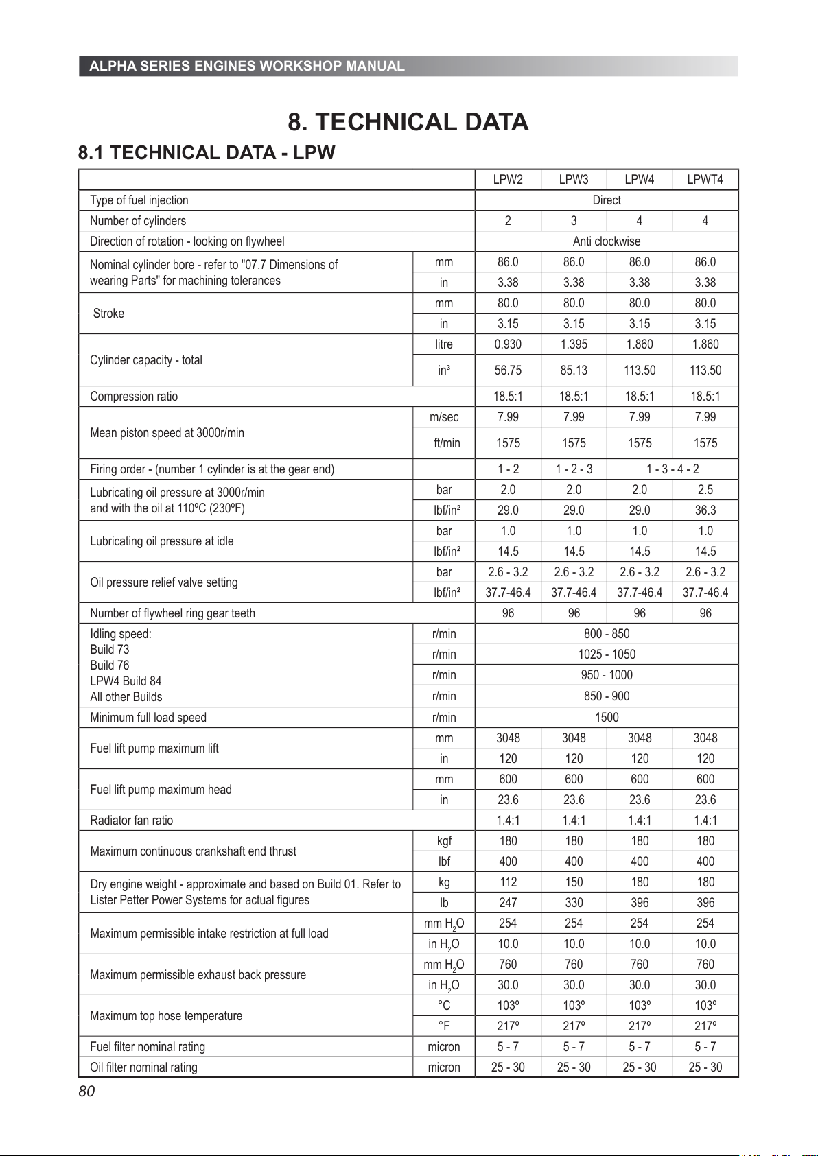
ALPHA SERIES ENGINES WORKSHOP MANUAL
80
8. TECHNICAL DATA
8.1 TECHNICAL DATA - LPW
LPW2 LPW3 LPW4 LPWT4
Type of fuel injection Direct
Number of cylinders 2 3 4 4
Direction of rotation - looking on flywheel Anti clockwise
Nominal cylinder bore - refer to "07.7 Dimensions of
wearing Parts" for machining tolerances
mm 86.0 86.0 86.0 86.0
in 3.38 3.38 3.38 3.38
Stroke
mm 80.0 80.0 80.0 80.0
in 3.15 3.15 3.15 3.15
Cylinder capacity - total
litre 0.930 1.395 1.860 1.860
in³ 56.75 85.13 113.50 113.50
Compression ratio 18.5:1 18.5:1 18.5:1 18.5:1
Mean piston speed at 3000r/min
m/sec 7.99 7.99 7.99 7.99
ft/min 1575 1575 1575 1575
Firing order - (number 1 cylinder is at the gear end) 1 - 2 1 - 2 - 3 1 - 3 - 4 - 2
Lubricating oil pressure at 3000r/min
and with the oil at 110ºC (230ºF)
bar 2.0 2.0 2.0 2.5
lbf/in² 29.0 29.0 29.0 36.3
Lubricating oil pressure at idle
bar 1.0 1.0 1.0 1.0
lbf/in² 14.5 14.5 14.5 14.5
Oil pressure relief valve setting
bar 2.6 - 3.2 2.6 - 3.2 2.6 - 3.2 2.6 - 3.2
lbf/in² 37.7-46.4 37.7-46.4 37.7-46.4 37.7-46.4
Number of flywheel ring gear teeth 96 96 96 96
Idling speed:
Build 73
Build 76
LPW4 Build 84
All other Builds
r/min 800 - 850
r/min 1025 - 1050
r/min 950 - 1000
r/min 850 - 900
Minimum full load speed r/min 1500
Fuel lift pump maximum lift
mm 3048 3048 3048 3048
in 120 120 120 120
Fuel lift pump maximum head
mm 600 600 600 600
in 23.6 23.6 23.6 23.6
Radiator fan ratio 1.4:1 1.4:1 1.4:1 1.4:1
Maximum continuous crankshaft end thrust
kgf 180 180 180 180
lbf 400 400 400 400
Dry engine weight - approximate and based on Build 01. Refer to
Lister Petter Power Systems for actual figures
kg 112 150 180 180
lb 247 330 396 396
Maximum permissible intake restriction at full load
mm H
2
O 254 254 254 254
in H
2
O 10.0 10.0 10.0 10.0
Maximum permissible exhaust back pressure
mm H
2
O 760 760 760 760
in H
2
O 30.0 30.0 30.0 30.0
Maximum top hose temperature
°C 103º 103º 103º 103º
°F 217º 217º 217º 217º
Fuel filter nominal rating micron 5 - 7 5 - 7 5 - 7 5 - 7
Oil filter nominal rating micron 25 - 30 25 - 30 25 - 30 25 - 30
All manuals and user guides at all-guides.com
Page 81
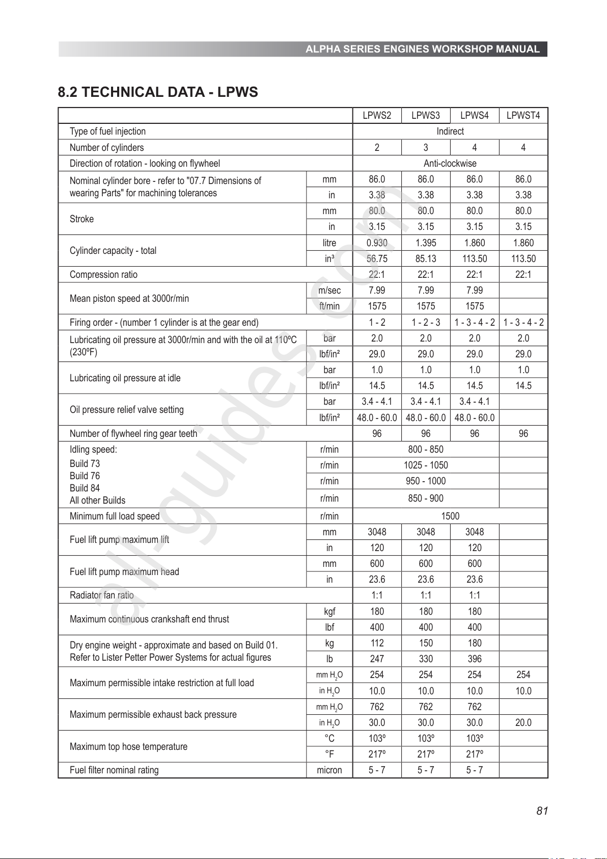
ALPHA SERIES ENGINES WORKSHOP MANUAL
81
8.2 TECHNICAL DATA - LPWS
LPWS2 LPWS3 LPWS4 LPWST4
Type of fuel injection Indirect
Number of cylinders 2 3 4 4
Direction of rotation - looking on flywheel Anti-clockwise
Nominal cylinder bore - refer to "07.7 Dimensions of
wearing Parts" for machining tolerances
mm 86.0 86.0 86.0 86.0
in 3.38 3.38 3.38 3.38
Stroke
mm 80.0 80.0 80.0 80.0
in 3.15 3.15 3.15 3.15
Cylinder capacity - total
litre 0.930 1.395 1.860 1.860
in³ 56.75 85.13 113.50 113.50
Compression ratio 22:1 22:1 22:1 22:1
Mean piston speed at 3000r/min
m/sec 7.99 7.99 7.99
ft/min 1575 1575 1575
Firing order - (number 1 cylinder is at the gear end) 1 - 2 1 - 2 - 3 1 - 3 - 4 - 2 1 - 3 - 4 - 2
Lubricating oil pressure at 3000r/min and with the oil at 110ºC
(230ºF)
bar 2.0 2.0 2.0 2.0
lbf/in² 29.0 29.0 29.0 29.0
Lubricating oil pressure at idle
bar 1.0 1.0 1.0 1.0
lbf/in² 14.5 14.5 14.5 14.5
Oil pressure relief valve setting
bar 3.4 - 4.1 3.4 - 4.1 3.4 - 4.1
lbf/in² 48.0 - 60.0 48.0 - 60.0 48.0 - 60.0
Number of flywheel ring gear teeth 96 96 96 96
Idling speed:
Build 73
Build 76
Build 84
All other Builds
r/min 800 - 850
r/min 1025 - 1050
r/min 950 - 1000
r/min 850 - 900
Minimum full load speed r/min 1500
Fuel lift pump maximum lift
mm 3048 3048 3048
in 120 120 120
Fuel lift pump maximum head
mm 600 600 600
in 23.6 23.6 23.6
Radiator fan ratio 1:1 1:1 1:1
Maximum continuous crankshaft end thrust
kgf 180 180 180
lbf 400 400 400
Dry engine weight - approximate and based on Build 01.
Refer to Lister Petter Power Systems for actual figures
kg 112 150 180
lb 247 330 396
Maximum permissible intake restriction at full load
mm H2O
254 254 254 254
in H2O
10.0 10.0 10.0 10.0
Maximum permissible exhaust back pressure
mm H2O
762 762 762
in H2O
30.0 30.0 30.0 20.0
Maximum top hose temperature
°C 103º 103º 103º
°F 217º 217º 217º
Fuel filter nominal rating micron 5 - 7 5 - 7 5 - 7
All manuals and user guides at all-guides.com
all-guides.com
Page 82
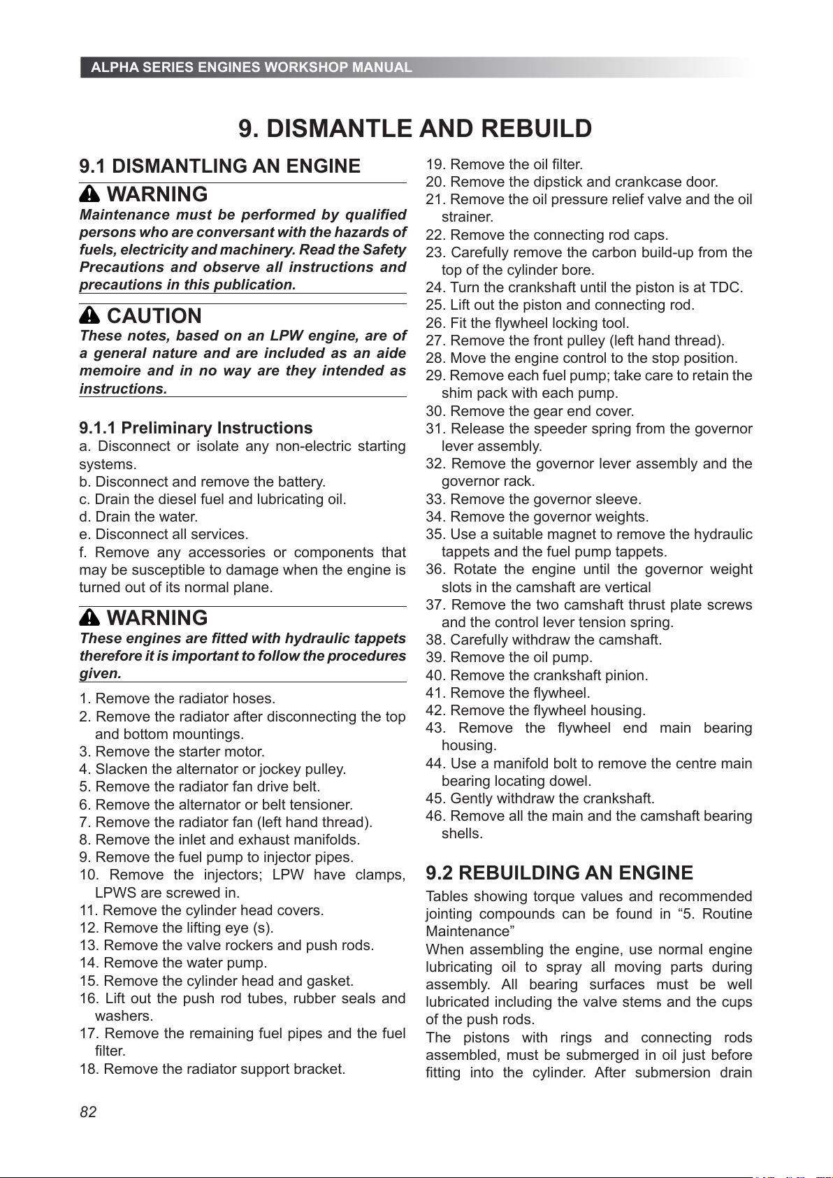
ALPHA SERIES ENGINES WORKSHOP MANUAL
82
9. DISMANTLE AND REBUILD
9.1 DISMANTLING AN ENGINE
WARNING
Maintenance must be performed by qualied
persons who are conversant with the hazards of
fuels, electricity and machinery. Read the Safety
Precautions and observe all instructions and
precautions in this publication.
CAUTION
These notes, based on an LPW engine, are of
a general nature and are included as an aide
memoire and in no way are they intended as
instructions.
9.1.1 Preliminary Instructions
a. Disconnect or isolate any non-electric starting
systems.
b. Disconnect and remove the battery.
c. Drain the diesel fuel and lubricating oil.
d. Drain the water.
e. Disconnect all services.
f. Remove any accessories or components that
may be susceptible to damage when the engine is
turned out of its normal plane.
WARNING
These engines are tted with hydraulic tappets
therefore it is important to follow the procedures
given.
1. Remove the radiator hoses.
2. Remove the radiator after disconnecting the top
and bottom mountings.
3. Remove the starter motor.
4. Slacken the alternator or jockey pulley.
5. Remove the radiator fan drive belt.
6. Remove the alternator or belt tensioner.
7. Remove the radiator fan (left hand thread).
8. Remove the inlet and exhaust manifolds.
9. Remove the fuel pump to injector pipes.
10. Remove the injectors; LPW have clamps,
LPWS are screwed in.
11. Remove the cylinder head covers.
12. Remove the lifting eye (s).
13. Remove the valve rockers and push rods.
14. Remove the water pump.
15. Remove the cylinder head and gasket.
16. Lift out the push rod tubes, rubber seals and
washers.
17. Remove the remaining fuel pipes and the fuel
lter.
18. Remove the radiator support bracket.
19. Remove the oil lter.
20. Remove the dipstick and crankcase door.
21. Remove the oil pressure relief valve and the oil
strainer.
22. Remove the connecting rod caps.
23. Carefully remove the carbon build-up from the
top of the cylinder bore.
24. Turn the crankshaft until the piston is at TDC.
25. Lift out the piston and connecting rod.
26. Fit the ywheel locking tool.
27. Remove the front pulley (left hand thread).
28. Move the engine control to the stop position.
29. Remove each fuel pump; take care to retain the
shim pack with each pump.
30. Remove the gear end cover.
31. Release the speeder spring from the governor
lever assembly.
32. Remove the governor lever assembly and the
governor rack.
33. Remove the governor sleeve.
34. Remove the governor weights.
35. Use a suitable magnet to remove the hydraulic
tappets and the fuel pump tappets.
36. Rotate the engine until the governor weight
slots in the camshaft are vertical
37. Remove the two camshaft thrust plate screws
and the control lever tension spring.
38. Carefully withdraw the camshaft.
39. Remove the oil pump.
40. Remove the crankshaft pinion.
41. Remove the ywheel.
42. Remove the ywheel housing.
43. Remove the ywheel end main bearing
housing.
44. Use a manifold bolt to remove the centre main
bearing locating dowel.
45. Gently withdraw the crankshaft.
46. Remove all the main and the camshaft bearing
shells.
9.2 REBUILDING AN ENGINE
Tables showing torque values and recommended
jointing compounds can be found in “5. Routine
Maintenance”
When assembling the engine, use normal engine
lubricating oil to spray all moving parts during
assembly. All bearing surfaces must be well
lubricated including the valve stems and the cups
of the push rods.
The pistons with rings and connecting rods
assembled, must be submerged in oil just before
tting into the cylinder. After submersion drain
All manuals and user guides at all-guides.com
Page 83
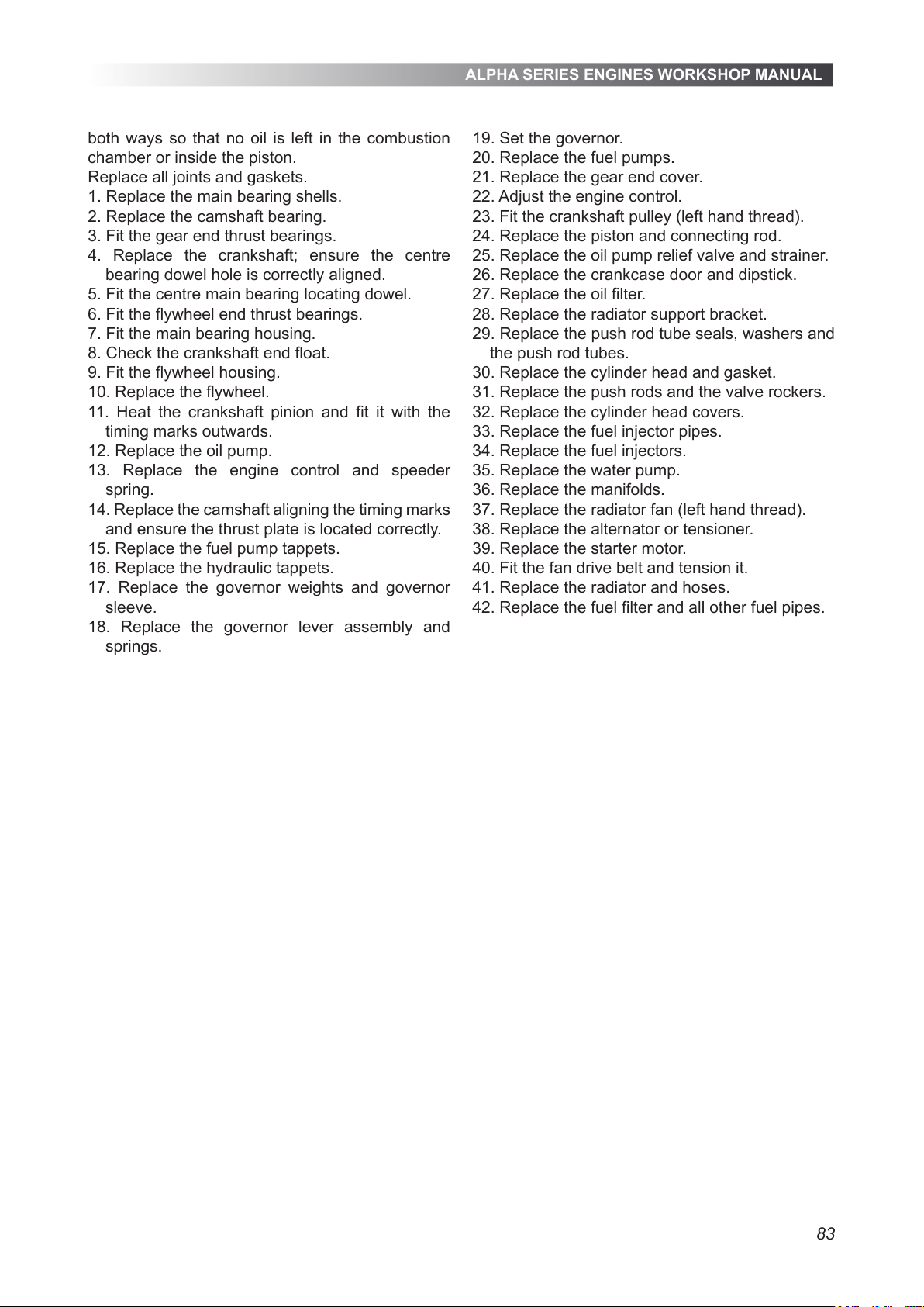
ALPHA SERIES ENGINES WORKSHOP MANUAL
83
both ways so that no oil is left in the combustion
chamber or inside the piston.
Replace all joints and gaskets.
1. Replace the main bearing shells.
2. Replace the camshaft bearing.
3. Fit the gear end thrust bearings.
4. Replace the crankshaft; ensure the centre
bearing dowel hole is correctly aligned.
5. Fit the centre main bearing locating dowel.
6. Fit the ywheel end thrust bearings.
7. Fit the main bearing housing.
8. Check the crankshaft end oat.
9. Fit the ywheel housing.
10. Replace the ywheel.
11. Heat the crankshaft pinion and t it with the
timing marks outwards.
12. Replace the oil pump.
13. Replace the engine control and speeder
spring.
14. Replace the camshaft aligning the timing marks
and ensure the thrust plate is located correctly.
15. Replace the fuel pump tappets.
16. Replace the hydraulic tappets.
17. Replace the governor weights and governor
sleeve.
18. Replace the governor lever assembly and
springs.
19. Set the governor.
20. Replace the fuel pumps.
21. Replace the gear end cover.
22. Adjust the engine control.
23. Fit the crankshaft pulley (left hand thread).
24. Replace the piston and connecting rod.
25. Replace the oil pump relief valve and strainer.
26. Replace the crankcase door and dipstick.
27. Replace the oil lter.
28. Replace the radiator support bracket.
29. Replace the push rod tube seals, washers and
the push rod tubes.
30. Replace the cylinder head and gasket.
31. Replace the push rods and the valve rockers.
32. Replace the cylinder head covers.
33. Replace the fuel injector pipes.
34. Replace the fuel injectors.
35. Replace the water pump.
36. Replace the manifolds.
37. Replace the radiator fan (left hand thread).
38. Replace the alternator or tensioner.
39. Replace the starter motor.
40. Fit the fan drive belt and tension it.
41. Replace the radiator and hoses.
42. Replace the fuel lter and all other fuel pipes.
All manuals and user guides at all-guides.com
Page 84
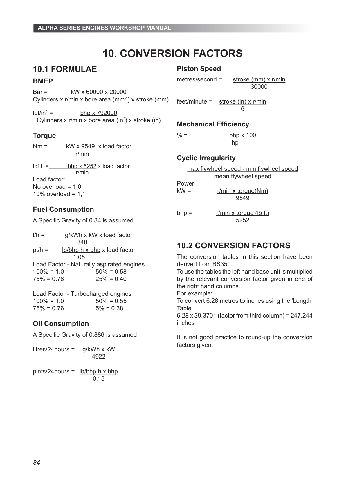
ALPHA SERIES ENGINES WORKSHOP MANUAL
84
10.1 FORMULAE
BMEP
Bar = kW x 60000 x 20000
Cylinders x r/min x bore area (mm2 ) x stroke (mm)
lbf/in2 = bhp x 792000
Cylinders x r/min x bore area (in2) x stroke (in)
Torque
Nm = kW x 9549 x load factor
r/min
lbf ft = bhp x 5252 x load factor
r/min
Load factor:
No overload = 1,0
10% overload = 1,1
Fuel Consumption
A Specic Gravity of 0.84 is assumed
l/h = g/kWh x kW x load factor
840
pt/h = lb/bhp h x bhp x load factor
1.05
Load Factor - Naturally aspirated engines
100% = 1.0 50% = 0.58
75% = 0.78 25% = 0.40
Load Factor - Turbocharged engines
100% = 1.0 50% = 0.55
75% = 0.76 5% = 0.38
Oil Consumption
A Specic Gravity of 0.886 is assumed
litres/24hours = g/kWh x kW
4922
pints/24hours = lb/bhp h x bhp
0.15
Piston Speed
metres/second = stroke (mm) x r/min
30000
feet/minute = stroke (in) x r/min
6
Mechanical Efciency
% = bhp x 100
ihp
Cyclic Irregularity
max ywheel speed - min ywheel speed
mean ywheel speed
Power
kW = r/min x torque(Nm)
9549
bhp = r/min x torque (lb ft)
5252
10.2 CONVERSION FACTORS
The conversion tables in this section have been
derived from BS350.
To use the tables the left hand base unit is multiplied
by the relevant conversion factor given in one of
the right hand columns.
For example:
To convert 6.28 metres to inches using the 'Length'
Table
6.28 x 39.3701 (factor from third column) = 247.244
inches
It is not good practice to round-up the conversion
factors given.
10. CONVERSION FACTORS
All manuals and user guides at all-guides.com
Page 85
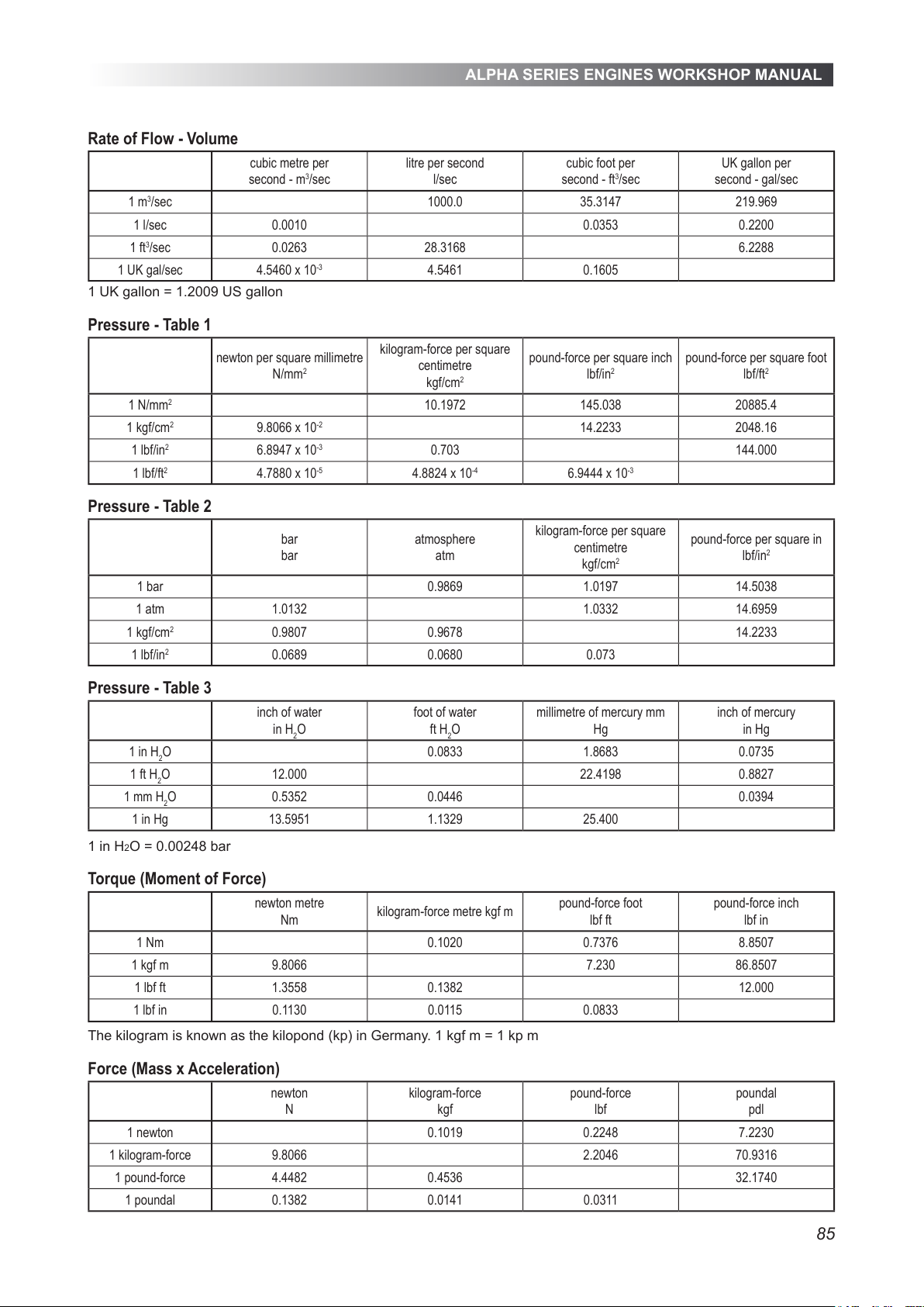
ALPHA SERIES ENGINES WORKSHOP MANUAL
85
Rate of Flow - Volume
cubic metre per
second - m3/sec
litre per second
l/sec
cubic foot per
second - ft3/sec
UK gallon per
second - gal/sec
1 m3/sec 1000.0 35.3147 219.969
1 l/sec 0.0010 0.0353 0.2200
1 ft3/sec 0.0263 28.3168 6.2288
1 UK gal/sec 4.5460 x 10
-3
4.5461 0.1605
1 UK gallon = 1.2009 US gallon
Pressure - Table 1
newton per square millimetre
N/mm
2
kilogram-force per square
centimetre
kgf/cm
2
pound-force per square inch
lbf/in
2
pound-force per square foot
lbf/ft
2
1 N/mm
2
10.1972 145.038 20885.4
1 kgf/cm
2
9.8066 x 10
-2
14.2233 2048.16
1 lbf/in
2
6.8947 x 10
-3
0.703 144.000
1 lbf/ft
2
4.7880 x 10
-5
4.8824 x 10
-4
6.9444 x 10
-3
Pressure - Table 2
bar
bar
atmosphere
atm
kilogram-force per square
centimetre
kgf/cm
2
pound-force per square in
lbf/in
2
1 bar 0.9869 1.0197 14.5038
1 atm 1.0132 1.0332 14.6959
1 kgf/cm
2
0.9807 0.9678 14.2233
1 lbf/in
2
0.0689 0.0680 0.073
Pressure - Table 3
inch of water
in H2O
foot of water
ft H2O
millimetre of mercury mm
Hg
inch of mercury
in Hg
1 in H2O 0.0833 1.8683 0.0735
1 ft H2O 12.000 22.4198 0.8827
1 mm H2O 0.5352 0.0446 0.0394
1 in Hg 13.5951 1.1329 25.400
1 in H2O = 0.00248 bar
Torque (Moment of Force)
newton metre
Nm
kilogram-force metre kgf m
pound-force foot
lbf ft
pound-force inch
lbf in
1 Nm 0.1020 0.7376 8.8507
1 kgf m 9.8066 7.230 86.8507
1 lbf ft 1.3558 0.1382 12.000
1 lbf in 0.1130 0.0115 0.0833
The kilogram is known as the kilopond (kp) in Germany. 1 kgf m = 1 kp m
Force (Mass x Acceleration)
newton
N
kilogram-force
kgf
pound-force
lbf
poundal
pdl
1 newton 0.1019 0.2248 7.2230
1 kilogram-force 9.8066 2.2046 70.9316
1 pound-force 4.4482 0.4536 32.1740
1 poundal 0.1382 0.0141 0.0311
All manuals and user guides at all-guides.com
Page 86
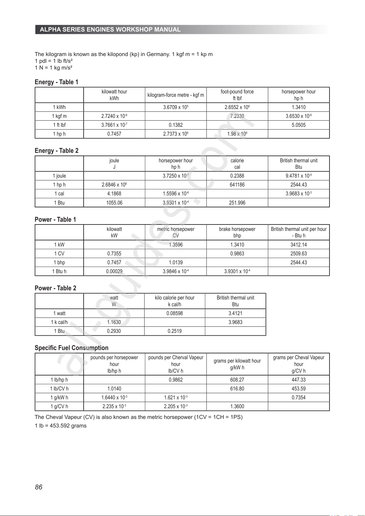
ALPHA SERIES ENGINES WORKSHOP MANUAL
86
The kilogram is known as the kilopond (kp) in Germany. 1 kgf m = 1 kp m
1 pdl = 1 lb ft/s²
1 N = 1 kg m/s²
Energy - Table 1
kilowatt hour
kWh
kilogram-force metre - kgf m
foot-pound force
ft lbf
horsepower hour
hp h
1 kWh 3.6709 x 10
5
2.6552 x 10
6
1.3410
1 kgf m 2.7240 x 10
-6
7.2330 3.6530 x 10
-6
1 ft lbf 3.7661 x 10
-7
0.1382 5.0505
1 hp h 0.7457 2.7373 x 10
6
1.98 x 10
6
Energy - Table 2
joule
J
horsepower hour
hp h
calorie
cal
British thermal unit
Btu
1 joule 3.7250 x 10
-7
0.2388 9.4781 x 10
-4
1 hp h 2.6846 x 10
6
641186 2544.43
1 cal 4.1868 1.5596 x 10
-6
3.9683 x 10
-3
1 Btu 1055.06 3.9301 x 10
-4
251.996
Power - Table 1
kilowatt
kW
metric horsepower
CV
brake horsepower
bhp
British thermal unit per hour
- Btu h
1 kW 1.3596 1.3410 3412.14
1 CV 0.7355 0.9863 2509.63
1 bhp 0.7457 1.0139 2544.43
1 Btu h 0.00029 3.9846 x 10
-4
3.9301 x 10
-4
Power - Table 2
watt
W
kilo calorie per hour
k cal/h
British thermal unit
Btu
1 watt 0.08598 3.4121
1 k cal/h 1.1630 3.9683
1 Btu 0.2930 0.2519
Specic Fuel Consumption
pounds per horsepower
hour
lb/hp h
pounds per Cherval Vapeur
hour
lb/CV h
grams per kilowatt hour
g/kW h
grams per Cheval Vapeur
hour
g/CV h
1 lb/hp h 0.9862 608.27 447.33
1 lb/CV h 1.0140 616.80 453.59
1 g/kW h 1.6440 x 10
-3
1.621 x 10
-3
0.7354
1 g/CV h 2.235 x 10
-3
2.205 x 10
-3
1.3600
The Cheval Vapeur (CV) is also known as the metric horsepower (1CV = 1CH = 1PS)
1 lb = 453.592 grams
All manuals and user guides at all-guides.com
all-guides.com
Page 87

87
All manuals and user guides at all-guides.com
Page 88
California Proposition 65 Warning
Diesel engine exhaust and some of its constituents are known to the State of California to cause
cancer, birth defects, and other reproductive harm.
Head Office
Lister Peter Power Systems Limited
Unit 14 Estuary Court, Broadmeadow Industrial Estate
Teignmouth, TQ14 9FA
T: +44 (0) 1285 702211
Production Facility
Lister Peter Power Systems Limited
Units 13-15 Quadrant Distribution Centre
Hardwicke, Gloucester, GL2 2RN
sales@listerpetter.com
www.listerpetter.com
ALPHA SERIES ENGINE WORKSHOP MANUAL
P027-08240, EDITION 15, NOVEMBER 2017
© LISTER PETTER POWER SYSTEMS
All manuals and user guides at all-guides.com
 Loading...