


L'ISOLANTE K-FLEX
LNG appLicatioNs MaNuaL

LNG APPLICATIONS MANUAL
The insulation LNG plants may forsee a multilayer design
according to the specific characteristics and the working
temperatures of the plants that need to be insulated.
In order to establish the correct scale of the insulation,
always refer to the project specifications and to the specific
“K-FLEX IN CLAD Piping Equipment Insulation Specification”
attached to this document.
L’ISOLANTE K-FLEX

INDICE
TOOLS NEEDED TO CARRY OUT THE INSULATION
ACCESSORIES
INSTALLATION INSTRUCTIONS
PREPARATIONS BEFORE STARTING
MULTILAYER INSULATION, PIPES
First layer
Middle layers
Installation K-FLEX IN CLAD covering
Pipe supports
MULTILAYER INSULATION, SPECIAL PARTS
Preformed “T” connection, first layer
Making the “T” connection sections on-site from sheets
Making the vapour barrier on the “T” connection
Preformed elbows: first layer
Elbows and “T” connections. Following layers (applies to the two, three or more layer designs)
Flanges
Insulation of the valves
Fixing the K-FLEX IN CLAD covering onto the “T” connection
Fixing the K-FLEX IN CLAD covering on flanges
Fixing the K-FLEX IN CLAD covering on valves
SPECIAL PREFORMED MULTILAYER SECTIONS
4
6
9
10
11
11
14
15
16
18
18
22
24
25
28
32
36
40
42
46
50
LIST OF DRAWINGS
STRAIGHT PIPE
PIPE SUPPORT
FLANGE
BLIND FLANGE
END CAP
ELBOW
“T” CONNECTION
CONCENTRIC REDUCTION
TECHNICAL SPECIFICATIONS
53
54
55
56
57
58
59
60
61
63

GENERAL PRINCIPLES
1° LNG insulations are all multilayered
2° The first layer is never glued
3° The joints of the first layer always have an expansion joint
4° The first layer is always covered with an aluminium/polyester vapour barrier
5° The first layer does not adhere perfectly to the pipe: an excess of 2-5%
is necessary to allow for thermal contraction of the insulation during use
6° The following layers are installed in the same way as those for traditional
applications for cold (glue and anticondensation tape on all joints and staggering
of the joints between the various layers
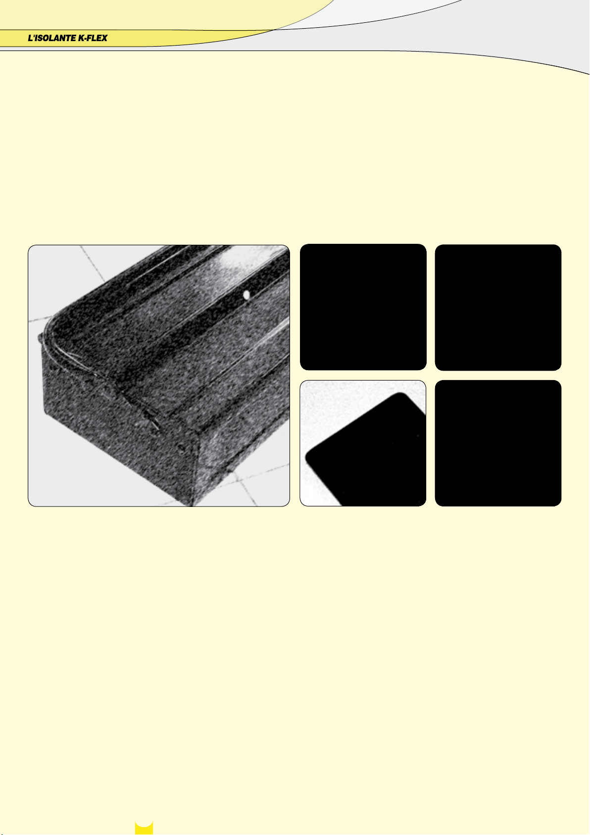
TOOLS NEEDED FOR THE JOB
compass brushes
spatula
marker pen
4
knife-shapening stone
scissors
ruler
knife
scalpel
compass to measure
diameters
chalk
sand paper
5
ACCESSORIES
TAPE, COVERING AND ADHESIVES
L’ISOLANTE K-FLEX advises using two types of tape: K-FLEX ST
anticondensation tape and K-FLEX ALU AA 130 tape.
anticondensation tape
Measurements
Thickness mm: 3
Lengths m: 10, 15
Widths mm: 50, 75, 100
ALU 5 LAYER FOIL
Measurements
Thickness: 80 µ
Length m: 100
Width mm: 1.000
ALU AA 130 Tape
Self-adhesive joint covering tape
in smooth aluminium
Measurements
Thickness: 30 µ
Length m: 50
Widths mm: 50, 75, 1000
K-FLEX IN CLAD COVERING
Measurements
Thickness mm: 1
Length m: 10
Width mm: 1.000
K-FL
EX IN CLAD TAPE
Measurements
Thickness: 1 mm
Length m: 25
Widths mm: 50, 100
6
TUBES
thickness mm 9
thickness mm 13
thickness mm 19
thickness mm 25
thickness mm 32
thickness mm 40
L'ISOLANTE K-FLEX does not accept responsibility for consumptions that may differ to those indicated above
k-fleX adhesiVes
K-FLEX K 420 glue has been specifically designed for use with K-FLEX
elastomeric foam insulation material. The securely bonded surfaces and
joints are resistant to ageing and atmospheric agents and preserve the
technical characteristics of the insulating material.
K 420
ADHESIVE in tins of: 0,26 - 1 - 2,6 litres
INDICATED CONSUMPTION OF 1 LITRE OF ADHESIVE
glued to the heads
every 1.350 m
every 500 m
every 300 m
every 220 m
every 180 m
every 139 m
glued lengthways
every 150 m
every 100 m
every 80 m
every 60 m
every 40 m
every 27 m
MARINE SEALANT
Marine sealant is suitable for making elastic constructive joints and has
extremely good UV-resistance and ageing properties.
Product is based on Silyl Modified Polymers.
Packaging: cartridges 290 ml
SPECIAL K-FLEX THINNERS
Before covering the surfaces to be insulated, it is advisable to clean them
thoroughly with the special K-FLEX thinners.
1 LITRE TINS
7
INSTALLATION INSTRUCTIONS
9
PREPARATION BEFORE STARTING TO INSULATE
1 2 3
1. C
LEANING THE SURFACE TO INSULATE.
Thoroughly degrease the surface to be insulated with the producer’s specified thinners
2)
STAGGERED LAYERS.
The insulation must be carried out, making sure that the end joints of tubes
(preformed up to a diameter of 168 mm) and of sheets (for diameters from
140-170 mm) are always staggered in order to ensure that the edges are
never aligned. In this way, starting to insulate from the pipe supports (fig.
1) where the sections are already staggered, the next layers are applied with
end joints that are not aligned.
5 6 7
4
3) CO
MPENSATION JOINTS.
Prepare a sufficient quantity of mineral fibre compensation joints according
to the following indications:
a) prepare several 30 mm thick mineral fibre strips;
b) cut sections with the same width as the insulation’s thickness eg. 50 mm
thickness, (fig. 2).
c) The mineral fibre strips should each be cut to a width of 50 mm. This
material will be used for making the compensation joints, (figs. from 2 - 4).
8
4. MAKING THE RIGHT SIZE TUBES FROM SHEETS
The insulation of the pipes can be carried out using preformed tubes, cut
out from sheets, or, when working on-site it is possible to use sheets for
insulating pipes of large dimensions. Usually preformed insulating tubes
are used for diameters from 140-170 mm whereas for greater diameters it
is easier to use sheets cut to size, as indicated further on in the manual, in
order to obtain the desired result, or one can even order the sheet section
already prepared for installing.
10
a) Cut a strip of K-FLEX ST elastomeric material of about 100 in width, fig. 5.
b) With the strip, measure the circumference of the pipe to insulate and
make a mark on the strip to indicate the correct circumference. Add to this
measurement an excess of 3% (fig. 6). NB: Gently lay the strip onto the
tube. Do not stretch, avoiding ending up with a section which is too short.
c) Lay the K-FLEX insulation sheet onto a flat surface and use the previously
cut strip to obtain the sheet sections needed to insulate the pipes, (figs.
7-8).
MULTILAYER INSULATION, PIPES
FIRST LAYER
9 10 11
1. APPLYING THE FIRST LAYER
a) apply the tube sections, previously cut out of a sheet, onto the pipes.
b) Seal the insulation together with 50 mm ALU AA 130 self-adhesive tape,
attaching strips every 30 cm perpendicularly to the cut, (fig. 9).
c) To make sure that the ALU AA 130 tape is correctly placed, press together the logitudinal edges of the insulation so that they touch and securely fixdown the tape, (fig. 10).
12 13 14
2.
INSTALLING THE COMPENSATION JOINTS
Between each insulated section, add a strip of previously prepared mineral
fibres, see pag. 10.
a) position the strip between the insulated tube sections, (fig. 12).
d) Once the tape is fixed perpendicularly, apply the tape along the complete
length of the tube to be insulated, over the joint, (fig. 11).
e) Rotate the logitudinal seal downwards, turning the insulation 180° to position the tube’s sealed joint towards the ground.
b) It is advisable to install the elastomeric material so that they come into
contact and then, using force, insert
the mineral fibres strip between the
end joints, (figs. 13-14).
11
MULTILAYER INSULATION, PIPES
FIRST LAYER
16
3. VAPOUR BARRIER
a) From a roll of ALU 5 layer foil, cut out a sheet with a width equal to one
and a half times the circumference of the insulated tube, (figs. 16-17).
18
17
19
b) Apply the sheet of ALU 5 layer foil onto the K-FLEX insulation, securely
fixing it down to obtain a tight fitting cover, (figs. 18-19).
12
All the edges of the vapour barrier must be staggered.
MULTILAYER INSULATION, PIPES
FIRST LAYER
20 21
c) It is important to stagger the edges of the insulation and the edges of the
ALU 5 layer foil in order to avoid continuity with the underlying edge. Every
sheet of ALU 5 layer foil should be positioned in such a way as to overlap
the following one by at least 100 mm between one section and another.
d) On both the longitudinal and end joints apply 50 mm ALU AA 130 selfadhesive tape to fix down the vapour barrier, (figs. 20-21).
13
MULTILAYER INSULATION, PIPES
MIDDLE LAYERS
22 23 24
INDICATIONS FOR CUTTING SHEETS TO SIZE
1. Repeat the procedure described above for carrying out the insulation of
the following layers, without adding any excess during the preparation of
the sheet sections.
2. Take care not to overlap the expansion joints of the following layers.
26 27
25
3. Use K-FLEX K-420 adhesive for sealing both the longitudinal and end joints of both the sheets and tubes, applying the glue with a brush on both the
sides to be sealed. Wait until the glue dries before installing the insulation
material, (figs. 22-24).
4. Install the insulation on the tube, taking care to avoid positioning the joints above those of the underlying layer. (first or second layer), (fig.25).
27a 27b
5. Apply, only on the second layer, 50 mm K-Flex anticondensation tape on
all the longidudinal and (fig. 26) head joints which were previously glued
together, (fig. 27).
14
6. For layers applied after the second one, it is not necessary to use (figs.
27 - 27b) anticondensation tape.
MULTILAYER INSULATION, PIPES
INSTALLING THE K-FLEX IN CLAD COVERING
28 29 29
1. PREPARATION OF IN-CLAD
From a roll of K-FLEX IN CLAD, cut a sheet with the same width as the
circumference of the insulated tube, adding an excess of roughly 50 mm for
the longitudinal overlap.
2.
INSTALLATION
a) Apply a layer of K-FLEX K-420 glue along the section of the tube to be
covered with K-FLEX IN CLAD.
b) Position the K-FLEX IN CLAD on the area where the glue has been applied and from that point wrap the K-FLEX IN CLAD sheet around the whole
section.
31
32 33
30
c) Securely press down the K-FLEX IN CLAD covering along the whole circumference, in order to obtain a tightly fitting cover, fig. 29.
d) With a brush, apply K-FLEX K-420 adhesive on both ends in order to
obtain a perfect seal against water between the covering and the insulation
material, (figs. 30-32).
NB: Take care to stagger the edges of the insulation and the the edges of
K-FLEX IN CLAD to avoid continuity with the underlying edge.
Each sheet of K-FLEX IN CLAD should be positioned in such a way as to
overlap the next sheet by at least 50 mm. Use K-FLEX K-420 on both the
longitudinal and transverse overlaps.
34
3.
SEALING WITH MARINE SEALANT
In order to obtain a covering with a secure water barrier, use marine sealant
approved by L’ISOLANTE K-FLEX on all the joints:
- Between all the longitudinal and transverse overlaps of the K-FLEX IN
CLAD covering
- Betwen the pipe supports and the K-FLEX IN CLAD covering
- Between the overlaps of the valves, flanges, “T” connections and
terminals
- On the sections of the elbow covered with K-FLEX IN CLAD
- On all the overlaps and K-FLEX IN CLAD joints.
Proceed as follows on all the joints indicated in figures 33 and 34:
a) with the corect dispensor, spread a layer of marine sealant at least 10 mm
wide, (figs. 33 - 34).
b) check that there are no breaks in the seal
c) carefully follow the instructions indicated on the tin of sealant and check
the time required to obtain a secure and permanent seal.
15
MULTILAYER INSULATION, PIPES
PIPE SUPPORTS
35 36 37
4.PIPE SUPPORTS
For a correct installation of the PU pipe supports, proceed as follows:
a) On a work surface, position all the shell sections needed for the pipe
support
b) Apply Foster putty on the edges of the PU “shell” sections, (fig. 35).
c) On the tube, apply an elastic band as shown in figure 36, which will help
to hold the shells onto the tube.
d) Apply the support sections one at a time starting from the top and continuing in a clockwise direction, rotating then downwards, (fig. 37).
e) Use the correct tools at the ends of the pipe support (10 cm from the
right and left edges) to secure the support onto the tube, using sufficient
39 40 41
38
force in order to achieve a tight fit of the longitudinal shell sections.
Position two aluminium sheets under the jack to avoid ruining the supports,
(fig. 38).
f) Wrap around the appropriate reinforced fiberglass tape three times in the
following three positions, (fig. 39).
- On the side of the left jack towards the centre, at about 10 cm
- On the side of the right jack towards the centre, at about 10 cm
- At the centre of the pipe support
g) Remove both left and right jacks.
Proceed in the same way for the following layers taking care to:
- apply the vapour barrier on the first layer, leaving 100 mm of overlap on
42
each side, and apply 1,5 rotations of ALU 5 layer foil. Finally, seal the vapour
barrier with reinforced fiberglass tape, (fig. 40).
h) For all the following layers (fig. 41) of the pipe support, the vapour barrier should be positioned only when the installer has attached the metal
collars, (fig. 42); afterwards, proceed with the covering as follows:
- Measure the distance between the end of the metal collar and the pipe
support, add 50 mm of excess for the overlap and cut out a strip of K-FLEX
IN CLAD.
- Install this strip, taking care to glue the longitudinal and transverse over-
16
laps with K-FLEX K 420 adhesive.
- Apply marine sealant to all the joints around the pipe support.
- to avoid water infiltrations, cover all the openings around the supporting
collar with marine sealant, (fig. 42).
MULTILAYER INSULATION, PIPES
PIPE SUPPORTS
43 44 45
CONNECTION BETWEEN THE PIPE SUPPORT AND THE TUBE SECTIONS
a) First layer
On the edges, apply mineral fibre strips as previously carried out for the
elastomeric material, (fig. 43). Cover everything with the vapour barrier as
shown in figure 44.
b) Following layers
Glue the two ends of the supports to the elastomeric material using K-FLEX
K-420 adhesive.
Only on the second layer, apply 50 mm K-FLEX anticondensation tape on all
the glued joints, (fig. 45). In a three layer installation, on the third layer, it is
not necessary to apply anticondensation tape.
47 48 49
46
K-FL
EX IN CLAD COVERING
The pipe supports should be covered externally with K-FLEX IN CLAD. Proceed as follows:
a) Cut a section of K-FLEX IN CLAD equal to the external circumference of
the pipe support, plus 50 mm of longitudinal and transverse excess on all
sides, (fig. 46).
50
b) Wrap the covering around the pipe support, (fig. 47).
c) Apply K-420 glue on both the longitudinal and transverse overlaps of the
K-FLEX IN CLAD covering and also onto the areas below onto which the
overlaps will be glued, (fig. 48).
d) Join together the areas to be glued and apply enough force to ensure a
perfect sealing, (fig. 49).
C
OVERINGS
On both sides of all joints, apply a 10 mm layer of marine sealant, (fig.
50).
17
MULTILAYER INSULATION, SPECIAL PARTS
PREFORMED “T” CONNECTIONS, 1° LAYER
51 52 53
5. “T” CONNECTIONS
FIRST LAYER WITH “T” CONNECTION IN SECTIONS READY FOR INSTALLING
The “T” connection is made of two pieces ready for installation as shown
in figure 51. As previously indicated for straight sections, the installation
should be carried out following the multilayer design. The first layer must
never be glued; ALU AA 130 tape will be used to fix the “T” connection
sections to the pipe. Proceed as follows.
55 56 57
54
a) On the tube, apply the single precut “T” connection sections (fig. 51),
fixing them together with 50 mm ALU AA 130 self-adhesive tape along all
the joints (figs. 52, 53, 54). NB: first install the horizontal section (figs. 52
and above) followed by the vertical one (fig. 64 and following).
b) ALU AA 130 self-adhesive tape should be applied as shown in figures
55 to 58.
58
NB: The ALU AA 130 tape should be applied both longitudinaly and transversely over the joints, as shown in figures 52 to 58.
18
NB: The prepared “T” connection sections needed for the installation are
already supplied with a 3% excess. During the installation, this excess
should be maintained. Therefore only seal down what is necessary.

MULTILAYER INSULATION, SPECIAL PARTS
PREFORMED “T” CONNECTIONS, 1° LAYER
59
d) With controlled pressure, insert the mineral fibre strips into the joints as
shown in figure 59.
e) When this operation is complete, the “T” connection should now appear
as shown in figure 60.
60
19

MULTILAYER INSULATION, SPECIAL PARTS
MAKING THE “T” CONNECTION SECTIONS ON-SITE FROM SHEETS
61 62 63
The “T” connection sections can be easily made directly on-site by cutting
them out of a section of K-FLEX ST sheet. They should be made in two
sections, a horizontal and vertical one, (fig. 51).
Proceed as follows.
a) Horizontal section
Prepare a strip of K-FLEX ST elastomeric material about 100 mm wide, with
the same thickness as the insulation which will be used, in order to take
the measurements of the circumference, fig. 61. Do not stretch the strip,
avoiding creating a section that could be too short. Finally, add an excess
of 3%.
65
66 6867
64
- Transfer the measurements onto a K-FLEX ST sheet as indicated by the red
arrow in figure 75 for preparing the length.
- Measure the diameter of the “T” connection, (fig. 62).
- Transfer the measurements of the diameter onto a ruler, (fig. 63).
- Divide the measurement by 2 (fig. 64) to obtain the radius needed to trace
two semi-circles with a compass, (fig. 65).
- The width of the sheet (green arrow in fig. 65) should be equal to 3 times
that of the measured radius in figure 74. Whereas the length, as previously
indicated, is the same as the circumference of the “T” connection section,
as indicated in figure 66.
20
- Once the two semi-circles have been marked out with the point of a compass (fig. 67), start to cut them out along the lines with a sharp knife, (fig.
68).

MULTILAYER INSULATION, SPECIAL PARTS
MAKING THE “T” CONNECTION SECTIONS ON-SITE FROM SHEETS
69
- Apply the horizontal section of the “T” connection onto the pipe, (fig.
69).
- Fix the horizontal section together using ALU AA 130 tape as indicated in
figures 70 to 72.
73 74 75
70
71
72
76
P
reparing the vertical section
To prepare the vertical section of the “T” connection, proceed as follows:
- Take the measurements of the coupling arm section by resting the cut
sheet on it to use as a basis for measuring, (fig. 73).
- Divide a second K-FLEX ST sheet into four equal sections, using the
same method as indicated in figure 61. Draw a line parallel to the edge.
The distance from the edge must be equal to that of the difference in height
measured in figure 85. This line is needed to obtain the intersecting point
with the three previously drawn vertical lines to use as the center for the
following circles, (figs. 86 - 93).
21

MULTILAYER INSULATION, SPECIAL PARTS
MAKING THE “T” CONNECTION SECTIONS ON-SITE FROM SHEETS
78 79 80
- At this point, with the help of a metal ruler, trace 4 sections as indicated
in figures 78 and 79.
82 Fig.93 Fig.94
83 84 85
81
- With a white felt pen, draw a median line which exactly divides in two the
previously drawn section, (fig. 80).
- Finally draw the curves as indicated in figures 81 and 82.
Fig.95
- cut out the final shape following the lines, (fig. 83). - Measure the distance between the horizontal “T” connection section and
the next already installed section, (fig. 84).
Transfer the measurements onto the sheet (fig. 85) and cut out the horizontal section of the “T” connection, which is now ready to be installed.
22

MULTILAYER INSULATION, SPECIAL PARTS
MAKING THE “T” CONNECTION SECTIONS ON-SITE FROM SHEETS
86 87 88
- Install the section onto the pipe, fixing it together with 50 mm ALU AA 130
self-adhesive tape, as indicated in figures 86 to 90.
90
105
89
NB: The ALU AA 130 tape should be applied both transversely (figure 103),
and longitudinaly to the cut as shown in figure 90.
91
92
- Apply, in the intersection between one sheet and another, a 30 mm thick
strip of mineral wool; with the same thickness as the insulation which will
be used.
- Proceed to cut a few strips of mineral fibre as indicated in figure 105 and
previously on page 20, and insert them between the intersections as seen
in figures 91 and 92.
NB: Bearing in mind the function of these strips (to compensate for the contraction of the elastomeric sheet), it is advisable to install the elastomeric
material so that they come into contact, and then, using force, open them
apart to allow enough space for the wool.
23

MULTILAYER INSULATION, SPECIAL PARTS
APPLYING THE VAPOUR BARRIER ON THE “T” CONNECTION
93
PREFABRICATED VAPOUR BARRIER
- On the first insulated layer, apply the prefabricated, ALU 5 layer foil sec-
tions of the “T” connection, (fig. 93).
- Apply the vapour barrier securely, in order to obtain a tight fitting cover
which compensates for the 3% of excess previously added to the insulation,
(figs. 91 - 97).
- Cover each overlap with 50 mm ALU AA 130 self-adhesive tape, (figs. 95
- 96 - 98 - 99).
97 98
94
95
The final result will result in a perfect vapour barrier, (fig. 100).
99
96
100
MAKING THE VAPOUR BARRIER ON-SITE
Prepare the sections which will be applied to the insulation by cutting them
out of a sheet of ALU 5 layer foil, following the instructions indicated in
the previous pages for making the “T” connection with K-FLEX insulation.
Apply each sheet of 5 layer aluminium foil onto the insulation, fixing them
down securely in order to obtain a tightly fitting cover and to compensate
for the 3% of excess previously added to the insulation. Take care to stagger the edges of the insulation and the edges of the ALU 5 layer foil sheet to
avoid continuity with the underlying edge.
24
Every sheet of ALU 5 layer foil should be positioned in such a way as to
overlap the following sheet by at least 100 mm.
On both the longitudinal and tranverse overlaps, 50 mm ALU AA 130 selfadhesive tape should be used.

MULTILAYER INSULATION, SPECIAL PARTS
PREFORMED ELBOWS: FIRST LAYER
1 2
A) FIRST LAYER: ELBOW IN SECTIONS
- The first layer of the elbows must be constructed using precut sections,
ready to be installed, (fig. 1).
4 5 6
3
- On the pipe, apply the single precut elbow sections previously cut out of
a sheet of K-FLEX ST, closing them together with 50 mm ALU AA 130 selfadhesive tape along all the joints, (figs. 2 - 3).
7
- Repeat the operation and proceed to apply all the elbow sections.
NB: The elbow sections which have a straight side, the ones at the start and
at the end, can be used in a specular way, (fig. 1).
- Continue to apply ALU AA 130 self-adhesive tape to close all the sections,
as shown in figures 4- 5- 6- 7.
25

MULTILAYER INSULATION, SPECIAL PARTS
PREFORMED ELBOWS: FIRST LAYER
8
B
) COMPENSATION JOINTS
- Insert a mineral fibre strip (see previous pages for indications on how to
make mineral wool strips) between each section of the elbow.
10 Fig.20 Fig.20
9
NB: When this operation is complete, the elbow should resemble the photo
in figs. 9 (detail) and 10 (complete elbow).
11
12
C) VAPOUR BARRIER
- On the insulated first layer, apply the prefabricated elbow sections in ALU
5 layer foil (fig. 11), taking care to overlap each segment over the previous
one by at least 50 mm.
26
- Attach them securely, in order to obtain a tight fitting cover and close each
section with ALU AA 130 self-adhesive tape, (fig. 12).

MULTILAYER INSULATION, SPECIAL PARTS
PREFORMED ELBOWS: FIRST LAYER
13 14 15
- Repeat the previously indicated operations for all the elbow sections, (figs.
20 and 21).
16
Cover each overlap with 50 mm ALU AA 130 self-adhesive tape, (fig. 16).
27

MULTILAYER INSULATION, SPECIAL PARTS
ELBOWS AND “T” CONNECTIONS:
FOLLOWING LAYERS
ELBOWS
With preformed elbows:
a) Cut the preformed elbow along the lower spine, (figs. 18 - 19).
20 21 22
17 18
b) Apply K-FLEX K 420 glue on the cut edges and wait until the glue is
almost dry, (fig. 21).
19
23
c) Mount the elbow onto the tube, (fig. 20).
d) Starting from the two extremities, glue the joints together. Make sure that
both sides are well glued, also internally, (fig. 22).
28
e) Apply K-Flex K-420 glue on both the lateral edges and wait until the glue
is almost dry, (fig. 23).

MULTILAYER INSULATION, SPECIAL PARTS
ELBOWS AND “T” CONNECTIONS:
FOLLOWING LAYERS
23 24 25
f) Next, apply 50 mm K-FLEX anticondensation tape over all the glued joints,
(figs. 24 - 25).
27 28 29
26
P
reparing the elbows on-site from sheets
- First of all, measure the internal radius of the curve using a ruler with
another ruler lying perpendicular to it, as shown in figure 26.
30
- Using a compass, mark out the outline of the internal radius on the K-FLEX
sheet, using the corner of the square marked out on the insulating material
as the axis, (fig. 27).
- measure the exact circumference of the pipe using a strip of K-FLEX ST
sheet of the correct thickness and divide the circumference by two, and
mark the middle of the strip accordingly.
- Add the outer radius to the measurement of the inner radius and, using
the same axis, mark out a semicircle onto the sheet with the compass, (fig.
28).
- Cut the sheet accurately along the arc of the circle, (fig. 29).
- Place the section obtained on the reverse side of another sheet and use it
as a template to cut out a second, mirror image section, (fig. 30).
- Allow the glue to dry and stick the edges together, starting from the two
extremities.
- Finally, install the elbow and follow the same procedures already indicated
for preformed elbows, (figs. 23 - 24 - 25).
29
MULTILAYER INSULATION, SPECIAL PARTS
ELBOWS AND “T” CONNECTIONS:
FOLLOWING LAYERS
Fig.31 Fig.32 33
31 32
INSTALLATION OF THE 3° ELBOW LAYER
Proceed to install the third layer of the elbow as previously indicated for
the second layer (both for preformed elbows and elbows cut out of sheets
on -site).
NB: In the third layer do not use K-FLEX ST anticondensation tape. It is only
necessary to:
- Install the elbow
- Glue the joints with K-FLEX K-420 adhesive, (figs. 31 - 32).
35 36 37
34
IN
STALLATION OF THE SECOND “T” CONNECTION LAYER
- The installation of the second “T” connection layer must be carried out
with the same procedure as previously indicated on pages 19 and 25, both
for preformed “T” connections and for those made directly on-site from
sheets.
38
- However, there are certain aspects to take into consideration:
1. K-FLEX K-420 glue, which was not used on the first layer, must be used
on all the joints of the ”T” connection.
30
- Apply ST anticondensation tape over all the joints as indicated in figures
37 and 38.
At this point the “T” connection is ready to be covered with K-FLEX IN
CLAD, or in the case of the three layer design, the third elastomeric layer
can now be installed.
The procedure to follow for the third elastomeric layer is exactly the same
as that indicated for the second layer except that ST anticondensation tape
should not be applied.

MULTILAYER INSULATION, SPECIAL PARTS
ELBOWS AND “T” CONNECTIONS:
FOLLOWING LAYERS
39 40 41
APPLICATION OF THE THIRD “T” CONNECTION LAYER
- As previously indicated, the application of the third layer differs from that
of the previous one in as much as it is not necessary to apply ST anticondensation tape on the joints. The photos from 39 to 41 show the “T”
connection insulated with 3 layers.
31

MULTILAYER INSULATION, SPECIAL PARTS
FLANGES
42
INSTALLATION OF THE FIRST LAYER OF THE FLANGE COVER
- Measure the pipes’ circumference. Use the measurements of the two diameters to calculate the respective inner and outer radii, (fig. 42).
- After calculating the two radii, mark out the inner and outer circumferences of the rings on two separate squares of K-FLEX ST sheet.
- Attaching a sharp blade to the tip of the compass allows the first incision
to be made so that a knife can then be used to cut out the ring. However, a
knife alone can give acceptable results, (fig. 43).
Cut the rings out and make an opening on one side to attach them around
the pipes, (fig. 44).
46
43 44 45
47 48 49
Use Alu AA 130 tape to secure the ring onto the flange, (fig. 45).
Complete the insulation of the tubes on the left and right sides of the flange
as indicated in the above figures, (figs 46 - 47).
- Repeat the same operation for the other side of the flange, (fig. 48).
- Apply a strip of mineral fibres between the rubber ring and the pipe as
shown in figures 48 - 49.
32
- Measure the distance between the two rings, including the thickness of the
insulating material, (fig. 49).

MULTILAYER INSULATION, SPECIAL PARTS
FLANGES
50
- Use a strip of K-FLEX ST sheet of the same thickness to measure the
circumference of the insulating rings, (figs. 50 - 51).
- Transfer the measurements onto a K-FLEX sheet to obtain the outline of
the sleeve that will complete the flange’s insulation.
53
54
51 52
- Mount it around the rings and tape together the edges, (fig. 51).
- Fix it securely with Alu AA 130 tape as indicated in figure 52.
I
NSTALLING THE VAPOUR BARRIER
Measure the circumference of the insulated flange and the tube section,
(figs. 53-54).
33

MULTILAYER INSULATION, SPECIAL PARTS
FLANGES
55 56 57
- Transfer the measurements onto a sheet of ALU 5 layer foil using a com-
pass as shown in figure 55.
- With the compass, add 5 cm for the overlap and draw the circle, (fig.
56).
59 60 61
.58
- Make perpendicular internal and external cuts with a pair of scissors, (fig.
57).
- Make a cut as indicated in figure 58 and apply the vapour barrier onto the
flange as shown in figure 59.
- Repeat the same operation for the other side of the flange.
- Seal everything using Alu AA 130 tape, (fig. 60).
34
- Finish the vapour barrier with Alu AA 130 tape as indicated in figure 61.

MULTILAYER INSULATION, SPECIAL PARTS
FLANGES
62 63 64
SECOND FLANGE LAYER
- Repeat the operations previously carried out for the first layer to create the
second layer of the flange cover, (fig. 62).
- Use K-FLEX K-420 glue to seal together the second layer of the flange
cover, (figs. 63 - 64).
66 66 67
65
- Apply K-Flex ST anticondensation tape over all the joints, (figs. 65 - 66).
68
- Once the ST anticondensation tape has been applied, the insulation of the
flange should appear as in figure 66.
INSULATION OF THE 3° FLANGE LAYER
To apply the third insulation layer on the flange, follow the same procedure
indicated for the application of the second layer. However in this case it is
not necessary to apply K-FLEX ST anticondensation tape. To seal the flange
cover, as indicated for the second layer, use K-FLEX K-420 glue.
35

MULTILAYER INSULATION, SPECIAL PARTS
INSULATION OF THE VALVE
69 70 71
INSULATION OF THE VALVES
- Measure the diameter of the pipes and the flanges. Use these measure-
ments to calculate the relevant radii, (fig. 70).
- After calculating the radii, mark out the respective inner and outer circu-
mferences on two separate squares of K-FLEX ST sheet of the same thickness, (fig. 71).
73 .74 75
72
- Carefully cut out the rings.
- Make an opening so that they can be fitted over the pipes.
- Place a ring on the outside of the valve, (fig. 72).
76
- Fix the ring onto the valve with AA 130 tape as shown in figure 73
- Apply a strip of mineral fibre between the ring and the flange, (fig. 74).
- Apply a strip of K-FLEX ST sheet around the top part of the flange as indi-
cated in figure 74 and fix it with ALU AA 130 tape.
36
- Next, calculate the shape of the disc for the top of the flange.
- Measure the circumference of the supporting flange and the form of the
face plate around which the disc must fit. Mark out the measurements on a
section of of K-FLEX ST sheet and cut the disc out, (figs. 75 - 76 - 77).

MULTILAYER INSULATION, SPECIAL PARTS
INSULATION OF THE VALVE
77 78 79
- Make an opening so that the disc can be fitted over the face plate, (fig.
78).
- Position the disc over the face plate.
81 82 83
80
- Draw the outline of the sleeve section measurements onto a sheet of KFLEX ST sheet and draw a line down the middle.
- Measure the diameter of the stopcock housing.
- Divide the diameter by two to obtain the radius. Place the compass at the
end of the sleeve’s center line and draw a semicircle at each end, (fig. 80).
84
- If there are any imperfections along the cut edges, smooth them out so
that they precisely bond together.
- Fix the valve’s cover with Alu AA 130 tape, (fig.82).
APP
LYING THE VAPOUR BARRIER ONTO THE VALVE COVER
FIRST LAYER
The insulation of the valve on the first layer should be completed with the
vapour barrier made from ALU 5 layer foil. As already indicated in the previous sections for making the vapour barrier, proceed as follows:
- measure the internal and external diameters of the sides of the valve, (fig.
83).
- transfer these measurements onto a sheet of ALU 5 layer foil (see figures
55 to 58 on page 34) and cut out the covers in aluminium as shown in
figure 84.
37

MULTILAYER INSULATION, SPECIAL PARTS
INSULATION OF THE VALVE
85 86 87
- Position the previously prepared rings onto the left and right side and also
onto the cover of the valve, (figs. 85 - 86).
99 100
88
- take the measurement as indicated in figure 87 in order to prepare the
second section of the vapour barrier.
- transfer the measurements onto a sheet of ALU 5 layer foil and cut out the
shape using a pair of scissors.
101
- Once this section of the vapour barrier has been cut out, it should have the
same shape as shown in figure 99.
- Finally proceed to install this section onto the valve as shown in figure
100.
38
- Fix this section of the vapour barrier onto the valve with ALU AA 130 tape,
(figs. 100 - 101).

MULTILAYER INSULATION, SPECIAL PARTS
INSULATION OF THE VALVE
102 103 104
- Proceed to insulate the right and left tube sections of the valve with the
vapour barrier (already insulated with the first layer of K-FLEX ST).
- Measure the valve section which still needs to be covered with the vapour
barrier, (fig. 103).
106 107 108
105
- From a sheet of ALU 5 layer foil, cut out this section of the vapour barrier
and position it onto the valve, (figs. 104 - 105).
- Fix everything together with ALU AA 130 tape, (fig. 106).
109
39

MULTILAYER INSULATION, SPECIAL PARTS
FIXING THE K-FLEX IN CLAD COVERING ONTO THE “T” CONNECTION
1 2
FIXING THE K-FLEX IN CLAD COVERING
ONTO THE “T” CONNECTION
a) Thoroughly degrease each section of the prefabricated K-FLEX IN CLAD
“T” connection with the correct thinners.
b) The “T” connections are made in three pieces which should be directly
applied onto the elastomeric sections. First install the main section of the
“T” connection followed by the coupling sections.
5 6 7
3
c) Apply K-FLEX K 420 glue, as shown in figures 20 onwards, both to the
elastomeric material and the K-FLEX IN CLAD covering.
4
8
d) Once the K-FLEX IN CLAD covering is positioned onto the insulation,
carefully seal all the overlaps with K-FLEX K 420 glue, (fig. 6).
40
e) Finally, press the overlaps down with force to make sure that both surfaces firmly adhere together, (fig. 8).

MULTILAYER INSULATION, SPECIAL PARTS
FIXING THE K-FLEX IN CLAD COVERING ONTO THE “T” CONNECTION
9 10 11
f) Proceed to apply the K-FLEX IN CLAD covering onto the coupling, repeating the same procedure as before, (figs. 9 and 10).
13 14 15
12
g) Finally, spread glue over all the joints, (fig. 11).
e) The “T” connection is now ready to be sealed with marine sealant, (fig.
12).
16
APP
LYING MARINE SEALANT:
a) Apply a 10 mm layer of marine sealant on both sides of all the joints
b) Proceed carefully as indicated in figures 13 - 14.
c) Marine sealant should be applied to all joints as can be seen in figure
16.
41

MULTILAYER INSULATION, SPECIAL PARTS
FIXING THE K-FLEX IN CLAD COVERING ON THE FLANGE
17 18 19
APPLYING THE K-FLEX IN CLAD COVERING ONTO THE FLANGE
a) measure the internal and external diameters of the flange, (fig. 17).
b) using a compass, mark out the internal and external measurements onto
a sheet of K-FLEX IN CLAD. Add an excess of 5 cm to the external diameter
and trace a third circle, (fig. 18).
18 19 20
20
c) using a sharp knife, cut around the furthest circle to obtain the disc.
21
d) Make external and internal fringes on the disk as indicated in figures 19
and 20
e) The disk is now ready to be mounted onto the flange, (fig. 18).
f) Repeat the same operation to cover the other side of the flange.
g) Make an opening cut on the disk and slot it onto the flange, (fig.19).
42
h) Use K-FLEX K-420 glue to fix the disk onto the flange, (figs. 20 - 21).

MULTILAYER INSULATION, SPECIAL PARTS
FIXING THE K-FLEX IN CLAD COVERING ON THE FLANGE
22 23 24
i) tightly close the fringes of the disc, which have already been glued with
K-FLEX K-420, in order to obtain a perfect grip.
j) When installed, the disk should appear as in figure 23.
26 27 28
25
k) Proceed by measuring the central section of the flange, (fig. 24).
l) Transfer the measurements onto a sheet of K-FLEX IN CLAD and cut out
the required section, (fig. 25).
29
m) spread K-FLEX K-420 glue on the elastomeric material and wait until it
is almost dry.
n) Place the previously prepared strip of K-FLEX IN CLAD onto the flange.
o) To correctly attach the K-FLEX IN CLAD sheet, use K-FLEX K-420 glue
and allow it to almost dry before sealing down both edges .
43

MULTILAYER INSULATION, SPECIAL PARTS
FIXING THE K-FLEX IN CLAD COVERING ON THE FLANGE
30 31
APPLYING MARINE SEALANT:
a) Spread a 10 mm layer of marine sealant over both sides of all joints.
b) Proceed carefully as indicated in figures 38 - 40 of the following page.
44

MULTILAYER INSULATION, SPECIAL PARTS
FIXING THE K-FLEX IN CLAD COVERING ON THE ELBOWS
32 33 34
APPLYING K-FLEX IN CLAD COVERING ONTO THE ELBOWS
a) Apply the preformed K-FLEX IN CLAD elbow segments onto the elbow by
sealing them onto the elastomeric material with K-FLEX K- 420 glue.
b) After appling the K-FLEX K-420 glue, wait until it is almost dry before
fixing the segments onto the elbow.
38 39 40
35
c) The elbow segments should be fixed onto the throat with (figs.33 and
34) K-FLEX K-420 glue.
APP
LYING:
a) Spread a 10 mm layer of marine sealant over both sides of all joints.
b) Proceed carefully as indicated in figures 38 - 40.
45

MULTILAYER INSULATION, SPECIAL PARTS
FIXING THE K-FLEX IN CLAD COVERING ON THE VALVE
1
IN-CLAD COVERING: VALVES
To fix the K-FLEX IN CLAD covering on valves, proceed as follows:
a) Measure the distance between the disc and the existing lagging at its
nearest and furthest point, (fig. 1).
b) Mark the two different measurements on the dividing lines of the tracing,
as illustrated, then draw the intersecting lines from one extremity of the
shape to the other, (fig. 2).
2
3
c) Using the difference in the two lengths as a radius, draw circles around
the ends of the lines. Using the arcs of the circles, draw a continuous line
linking them up, as illustrated in figure 3.
7654
d) Add a third line which will be used as a guide to make the fringes, (fig.
5).
46
e) Proceed by making longitudinal cuts as shown in figure 6.
f) Apply the K-FLEX IN CLAD covering as shown in figures 7 and 8.

MULTILAYER INSULATION, SPECIAL PARTS
FIXING THE K-FLEX IN CLAD COVERING ON THE VALVE
8 9
g) Use K-FLEX K-420 glue to fix the K-FLEX IN CLAD covering onto the
insulation.
h) Apply the glue onto both the K-FLEX IN CLAD covering and the insulation
with a brush, (fig. 9).
NB: Wait until the glue is almost dry before proceeding with the installation.
i) Using pressure, firmly seal down all the previously prepared fringes.
12 13 14
10
PREPARING K-FLEX THE IN CLAD SIDE DISKS OF THE VALVE
a) Measure the internal and external diameters of the valve
b) using a compass, mark out the measurements of both the internal and
external diameters onto a sheet of K-FLEX IN CLAD. Add 5 cm to the to the
external diameter and trace a third circle which will be used for the overlap,
(fig. 11).
11
15
c) using a sharp knife, cut out around the external circumference to obtain
the disk.
d) Make internal and external fringes in the disk as indicated in figures 12
and 13.
e) The disk is now ready to be mounted onto the valve, (fig. 14).
f) Repeat the operation to cover the other side of the valve.
g) Make an opening cut in the disk and slot it onto the valve.
h) Use K-FLEX K-420 glue to seal the disc onto the valve, (fig. 15).
47

MULTILAYER INSULATION, SPECIAL PARTS
FIXING THE K-FLEX IN CLAD COVERING ON THE VALVE
16 17 18
i) Using pressure, fix down the disk fringes, previously spread with K-FLEX
K-420 glue, in order to obtain a perfect mechanical grip.
j) When the disk is installed, it should appear as in figure 16.
K-FL
EX IN CLAD VALVE COVER
Now proceed to make the valve cover with K-FLEX IN CLAD.
a) with a compass, take the measurements of the valve’s diameter
b) transfer the measurements onto a sheet of K-FLEX IN CLAD.
c) cut the disc as shown in figure 17.
20 21 22
19
d) On the previously prepared K-FLEX IN CLAD disk, carefully draw out the
protruding parts of the valve’s cover, (figs. 18 - 19).
23
e) With a sharp knife cut out the shapes and make an opening cut, (figs.
20 - 21).
48
f) proceed to install the disk, sealing it onto the valve with K-FLEX K-420
lue.
g

MULTILAYER INSULATION, SPECIAL PARTS
FIXING THE K-FLEX IN CLAD COVERING ON THE VALVE
24 25 26
g) proceed by spreading K-FLEX K 420 glue over all the valve’s K-FLEX IN
CLAD joints, (figs. 24 - 25 - 26).
28 29 30
27
h) Prepare a strip of K-FLEX IN CLAD sheet to apply around the valve’s
circumference as illustrated in figure 27.
20
i) Using K-FLX K-420 glue, seal the K-FLEX IN CLAD strip onto the valve. APPLYING MARINE SEALANT
a) Spread a 10 mm layer of marine sealant over both sides of all joints.
b) Proceed carefully as indicated in figure 20.
49

SPECIAL PREFORMED MULTILAYER SECTIONS
INSTALLING ELBOWS, “T” CONNECTIONS, FLANGES AND VALVES
50

PREFORMED “T” CONNECTION PREFORMED ELBOW
PREFORMED FLANGE
THE SPECIAL MULTILAYER PREFORMED SECTIONS MUST BE INSTALLED IN THE FOLLOWING WAY
1) Open the sections
2) Install the first layer
3) Install the vapour barrier
4) Install the second layer using ST self-adhesive anticondensation tape
5) Install the third layer
6) Install the K-FLEX IN CLAD covering
7) Apply marine sealant over all the joints
51

LIST OF DRAWINGS
535455


5657585960


61
 Loading...