

Page 1
HCS GDC D1
Grain Dryer Control
TECHNICAL DESCRIPTION
Page 2

HCS GDC D1 TECHNICAL DESCRIPTION
Table of Contents
1. This is HCS GDC D1
2. Manual Mode
3. Auto Mode
4. Restart
5. Connecting the HCS GDC D1
6. Instrumentation Amplier HCS-200
7. Mounting the Humidity Sensors HCS 4/3
3
4
5
6
7
9
10
2
APRIL 2019
Page 3
HCS GDC D1 TECHNICAL DESCRIPTION
1. This is HCS GDC D1
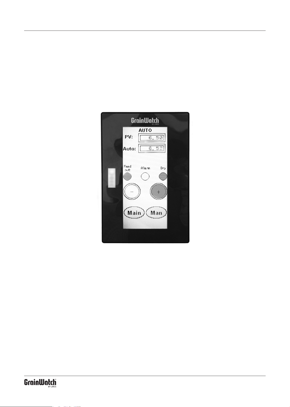
HCS GDC D1 is a Humidity Regulator / Control Unit,
for drying apparatus used for grain. HCS GDC D1 will
select feed-out speed from your grain dryer depending
on input from humidity sensors and your own settings.
It has two modes: Manual and Auto. When in
Manual mode the Humidity Sensors are not engaged.
When in Auto mode, the signal from the Humidity Sen-
sors are used as well as your Manual mode settings to
determine out-put speed.
In case the water content in the grain changes, the
out-put speed will change as well.
A continuous reading from the Humidity Sensors is
displayed on the Control Unit.
3
APRIL 2019
Page 4
HCS GDC D1 TECHNICAL DESCRIPTION
2. Manual Mode
Manual Mode – MAN – is a simple time-based pro-
gram in which drying times are set with a percentage
value that shows how much of the time the feed-out is
active.
Example: If MAN is set to 10%, the feed-out is running 10% of the time and inactive 90%. If the value is
set to 50%, the feed-out will run and be idle in a 50/50
relation, and so on.
It is recommended to move the dried commodity
to a wet silo so that damp cereals can continuously be
fed into the dryer. Check the moisture content of the
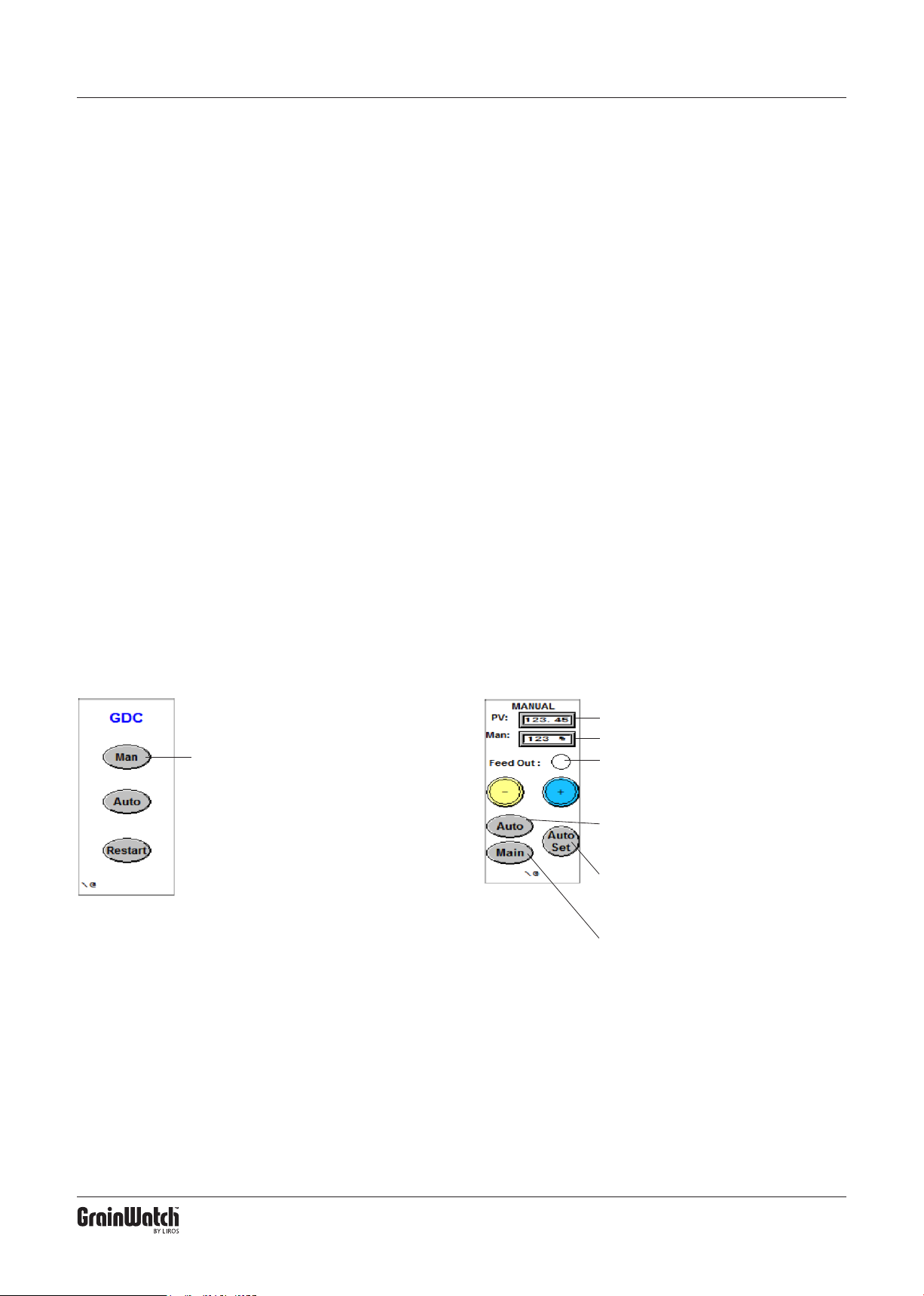
Step 1
Press “Man”
dried product regularly. If the outgoing grain is too wet,
lower the setting on the panel. Is the item instead is too
dry, raise the value.
When the desired moisture content is reached,
press “Auto Set “ after which the system will automatically set a value corresponding to the one used in
Manual mode.
If the “Auto” button is pressed directly without pre-
setting, the control automatically switches to the last
setting previously used by the auto function.
Step 2
PV: Shows the signal from the sensor.
Man: Shows the percentage set.
Feed Out: Lights up yellow when output is
active.
– : Decreases the set percentage (drier item).
+ : Increases the set percentage (wetter item).
Auto: Go to the Auto screen to set the control
on the auto value that was used the last time
auto mode was used.
Auto Set: To go to Auto, where the controller
loads a new auto value with respect to the
signal from the sensor (PV) and the percentage used when pressing the button.
Main: To go to the Home screen.
NOTE: When The dryer is empty, the signal value “PV” should be
4.00. If it is below 3.70 or above 4.30, the equipment needs service
and calibration.
4
APRIL 2019
Page 5
HCS GDC D1 TECHNICAL DESCRIPTION
3. Auto Mode
With Auto mode, the control is given a value from the
transducer displayed in the “PV” box. The value is dif-
ferent for different types of cereals with the same moisture content and changes according to the moisture
level of the cereals. Dry commodity = low value, wet
commodity = high value.
The Auto value setting is made either of an earlier
value used for the grain in the dryer, or from the “AutoSet” in a previous manual run (see chapter 2).
If, when checked, the water content is not the de-
sired, the autovalue can be changed with the plus and
minus buttons (Plus = higher value, wetter commodity,
Minus= lower value, drier commodity). However, never
change the autovalue more than 0.20 at a time.
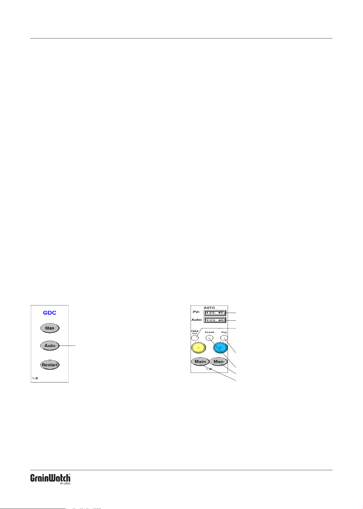
Step 1
Press “Auto”
After resetting values, let the dryer go for at least one
hour. Then check that the adjustments support the
desired result.
Normally, the Auto value should be between 5.00-
8.00 – Lowest value for dry commodity (oil seeds) or
commodity with a lot of shell (oats). Highest value for
wet commodity with little shell (wheat).
Feed Auto is lit when output is active. The output
time is normally 27 secs but it can be changed to 18
secs to get closer feedouts with less content each time.
Alarms are activated when the equipment has
made 6 feedouts on the longest drying time without
lowering the water content. When alarms are activated,
no further ejections are made.
Step 2
PV: Shows the signal from the sensor.
Man: Shows the percentage set.
Feed Out: Lights up yellow when output is
active.
– : Decreases the set percentage (drier item).
+ : Increases the set percentage (wetter item).
Dry: Lights up Green when the commodity is
drier than the set value.
Alarm: Red light when alarm is activated.
Man: To go to Manual mode.
Main: To go to Home screen.
5
APRIL 2019
Page 6
HCS GDC D1 TECHNICAL DESCRIPTION
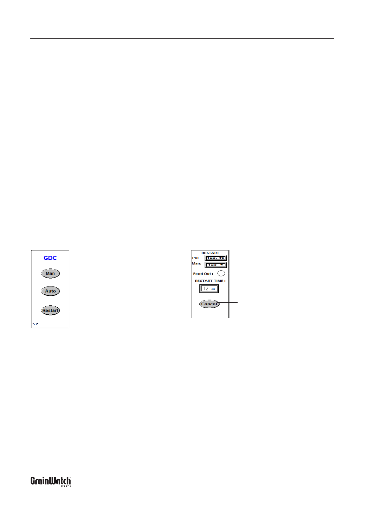
4. Restart Mode
Restart is used when the drying process has been
stopped and should be restarted. The control will
then switch to Manual mode with the setting from last
manual run.
The drying now runs for 60 minutes on Manual,
and then on Auto with the setting used for the last previous auto run. The process continues as a standard
auto run.
Step 1
Press “Restart”
When Restart is used the Percentage setting cannot
be changed. If requested, “Cancel” can be pressed to
return to the start page in which Manual mode can be
chosen to make the adjustment.
Once Restart is pressed again, a new 60 minute
manual run is restarted and switched over to Auto
mode, and so on.
Step 2
PV: Shows the signal from the sensor.
Man: Shows the percentage set.
Feed Out: Lights up yellow when output is
active.
Restart time: Shows the number of minutes
left before the control switches to Auto.
Cancel: Press to exit Restart and go to the
Home screen.
Please write down the settings to facilitate for the next occasion
the same kind of cereals are dried.
6
APRIL 2019
Page 7
HCS GDC D1 TECHNICAL DESCRIPTION
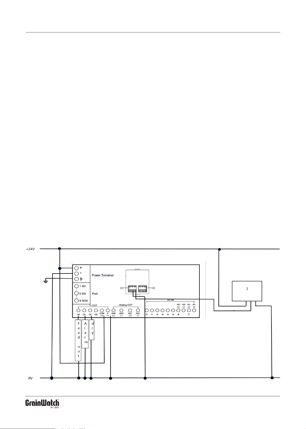
5. Connecting the HCS GDC D1
Voltage supply 24VDC. Note that the same power
source is to be used for the control unit, amplier and
any relays.
To control unit:
Power Terminal +24V for
Plus. 0 V for Minus
Outputs:
TR Out
Q0 = Feed Out (active during feed-out).
Q1= Alarm (active during alarm).
Q2= Dry (active when commodity is dry)
Amplier:
+24VDC to white cable.
0 V to brown cable.
Signal 4-20 mA to green cable.
A. Connection with only one sensor
Amplier
White
Green
7
Brown
APRIL 2019
Page 8
HCS GDC D1 TECHNICAL DESCRIPTION
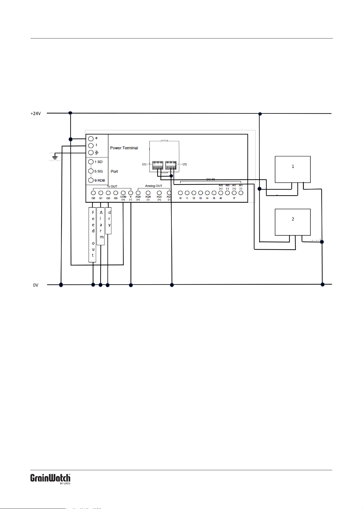
B. Connection with two sensors
Amplier
White
Green
Amplier
White
Green
Brown
Brown
8
APRIL 2019
Page 9
HCS GDC D1 TECHNICAL DESCRIPTION
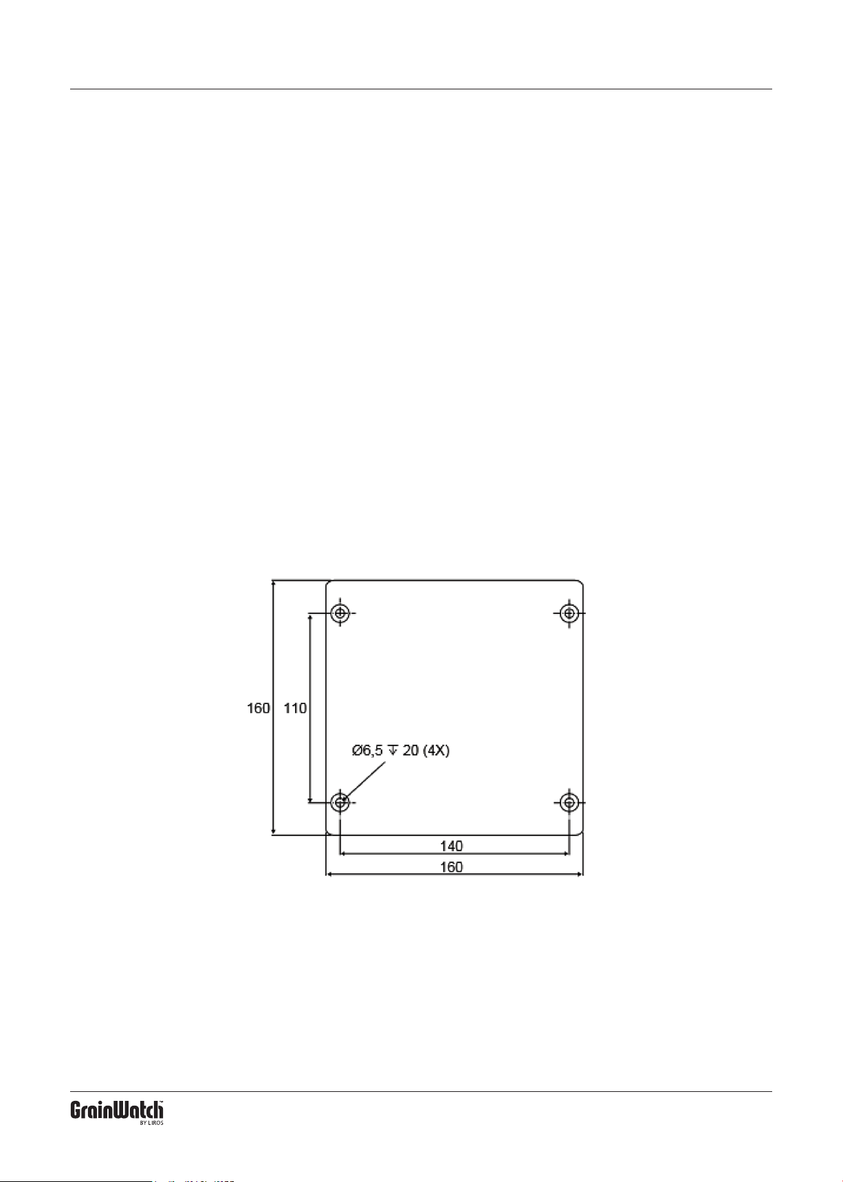
6. Instrumentation Amplifier HCS 200
The HCS 200 is encased in a rigid and dust proof box.
and connects to the Humidity Sensors with two wires.
The amplier should be mounted close to the dryer, indoors or outdoors, between the Humidity Sensors and
the HCS. Place the amplier where it is accessible for
service. There is approximately 1 meter of cable from
the Amplier to be connected to a junction box.
The cable from the junction box to the HCS must
be shielded, at least 3 * 0,5 mm2. The length is practi-
cally unlimited.
9
APRIL 2019
Page 10
HCS GDC D1 TECHNICAL DESCRIPTION
7. Mounting the Humidity Sensors HCS 4/3
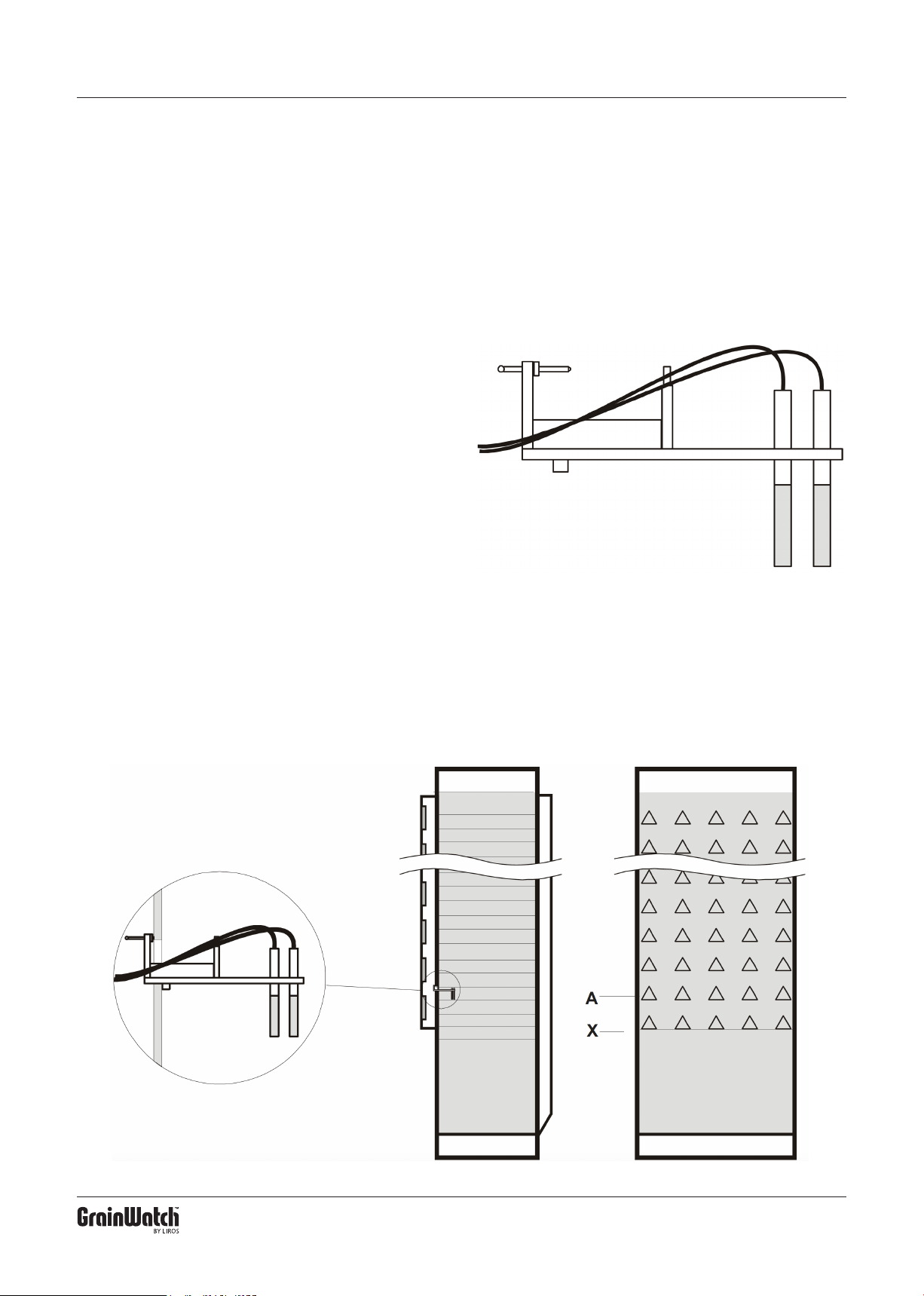
The HCS 4/3 consists of a holder with sensors and two
4 meter long cables, to be mounted inside the dryer
in accordance with the below instructions. The design
prevents straw from sticking to the sensors, thus omitting wrong readings.
Mounting inside the dryer is best done by hand
– no tools needed. Depending on the width of the dryer
one or two HCS 4/3 can be installed.
Shown in the picture below right is the rst row of
beams / members at the mark “X”, where the drying
zone meet up with the cooling zone. Level wise, HCS
4/3 should be mounted in the row of beams / members
at mark “A” on the intake side. If possible, place the
sensor unit in one of the air beams / air members in
such a way that it is placed 1/3 of the dryer’s full width
from one side. If this is non-applicable, you may mount
the sensor closer to the centre, not to the side. Example: When Dryer full width = 1,5 meter, the Sensor
should not be closer to one side than 0,5 meter.
10
APRIL 2019
Page 11
HCS GDC D1 TECHNICAL DESCRIPTION
In case you mount two sensor units, place them symmetrically / evenly spaced about half of the dryer’s full
width between the two.
Example: When Dryer full width = 4meter, distance
between Sensors should be 2 meters.
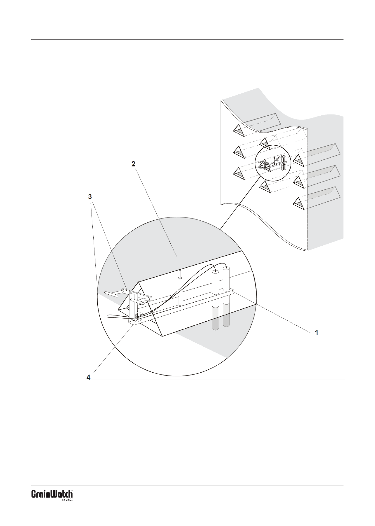
HCS 4/3 is designed to be easily mounted without
tools. Tighten screw “2” and unscrew the two screws,
called “3” slightly. Insert the HCS 4/3 inside the air
beam / air member.
The Sensor should rest in the triangular opening,
and the lip underneath must be inside the dryer.
Adjust screw “2” until the unit is horizontal then
handtighten screws “3” and make sure the sensor is
pointing straight into the air-beam / air member.
Tighten the screws until the HCS 4/3 is completely
xed, but do use too much force. Overtightening may
affect the unit’s brackets negatively.
11
APRIL 2019
Page 12
www.grainwatch.com
APRIL 2019
 Loading...