

Liquiflo MAX, MAX M2, MAX M3, MAX M6, MAX M7 Installation, Operation And Maintenance Manual
...Page 1
TM
INSTALLATION, OPERATION and MAINTENANCE MANUAL
MAX® SERIES
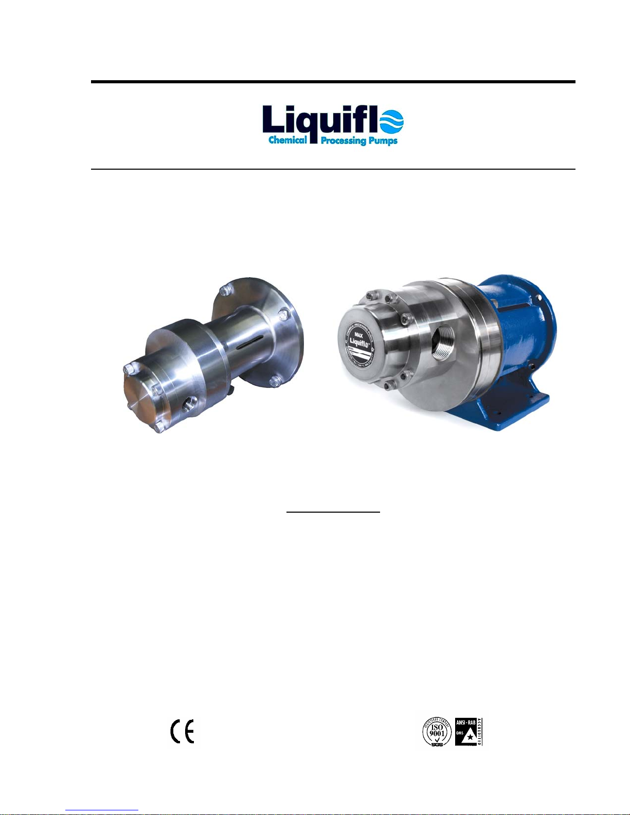
MECHANICALLY SEALED GEAR PUMPS
Sealed Models M2, M3 & M4 Sealed Models M5, M6, M7 & M8
Table of Contents
1. General Information . . . . . . . . . . . . . . . . . . . . . . . . . 2-3
2. Safety Precautions . . . . . . . . . . . . . . . . . . . . . . . . . . . 4
3. Pump & Motor Installation . . . . . . . . . . . . . . . . . . . . 5
4. Start-Up & Operation . . . . . . . . . . . . . . . . . . . . . . . . 6
5. Maintenance & Repair . . . . . . . . . . . . . . . . . . . . . . . 7-11
6. Exploded View Reference Drawings . . . . . . . . . . . . 12-13
7. Troubleshooting Guide . . . . . . . . . . . . . . . . . . . . . . . 14-15
© Feb. 2005 Document No.: 3.20.085
Liquiflo 443 North Avenue, Garwood, NJ 07027 USA Tel: 908-518-0777 Fax: 908-518-1847
Page 2
Liquiflo Installation, Operation & Maintenance Manual Max® Series Sealed Pumps
Models M2 thru M8
1. General Information
1.1 General Instructions
This manual covers the Max
The materials of construction of the pump are selected based upon the chemical compatibility of the fluid
being pumped. The user must verify that the materials are suitable for the surrounding atmosphere.
If the fluid is non-conductive, methods are available to mechanically ground the isolated shaft. This is
only necessary if the surrounding atmosphere is extremely explosive or stray static charges are present.
Upon receipt of your Liquiflo pump:
A) Verify that the equipment has not been damaged in transit.
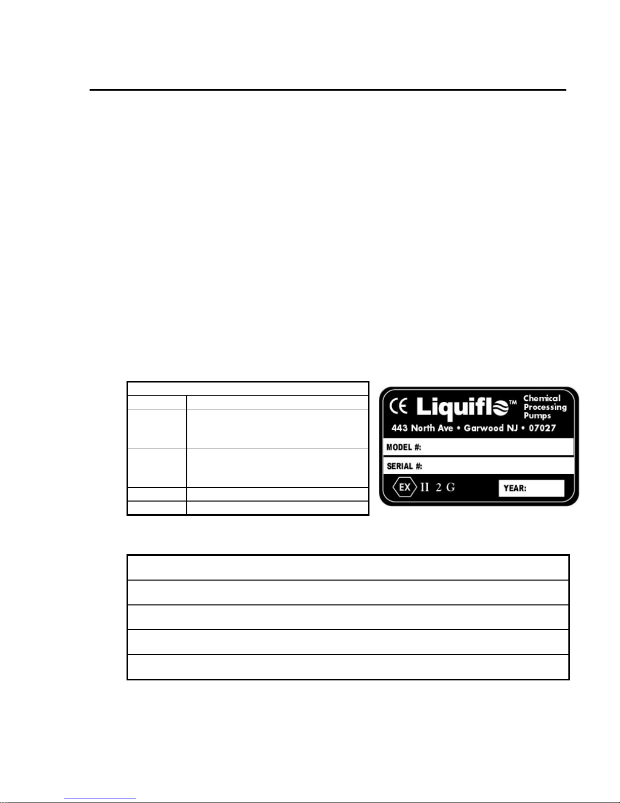
B) Verify that the pump Model Code and Serial Number are stamped on the circular tag on the rear
housing of the pump.
C) Verify that the Liquiflo Nameplate is secured to the pump.
D) Verify the Group and Category Codes:
Group II
Category
2
Category
3
D
G
E) Record the following information for future reference:
®
Series Sealed gear pumps, Models M2, M3, M4, M5, M6, M7 and M8.
Explanation of Nameplate
Explosive atmospheres
Equipment provides a high level of
protection. Explosive atmospheres
only are likely to occur.
Equipment provides a normal level of
protection. Explosive atmospheres
are unlikely to occur.
Dust
Gas
Model Code:
Serial Number:
Date Received:
Pump Location:
Pump Service:
NOTE: By adding a K prior to the pump's Model Code, a Repair Kit can be obtained which consists of
the following parts: mechanical seal, drive and idler gears, drive and idler shafts, wear plates, bearings,
retaining rings, keys, housing alignment pins, bearing lock pins and O-rings.
2
Page 3
Liquiflo Installation, Operation & Maintenance Manual Max® Series Sealed Pumps
Models M2 thru M8
1.2 Pump Specifications
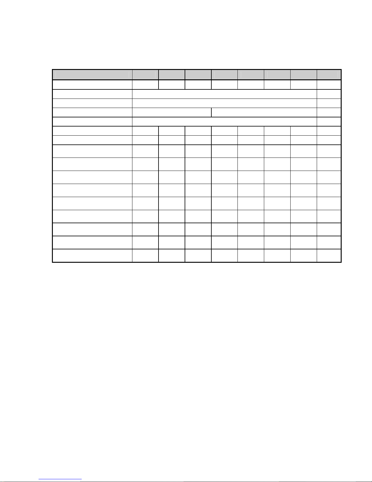
Max® Series SEALED Pump Specifications
Pump Model M2 M3 M4 M5 M6 M7 M8 Units
Port Size
Port Type
Body Material
Mounting Bracket
Mechanical Seal
1
RMS
Theoretical Displacement
Flow Rate @ RMS
Max Differential Pressure
Max System Pressure
Max Temperature
Min Temperature
Max Viscosity
NPSHR @ RMS
Suction Lift (dry) @ RMS
Weight
RMS = Recommended Maximum Speed
NPSHR = Net Positive Suction Head Required
7
5
6
3
4
FOOTNOTES:
1 Under special conditions, Models M2 thru M4 can be operated up to 3600 RPM. Consult factory.
2 Based on new pump operating at RMS and 0 PSI differential pressure.
3 Maximum differential pressure is dependent upon fluid being pumped. Consult factory.
4 Must be derated for flanged pumps, based on the flange and temperature of the application.
5 Pump may require trimmed parts depending on the materials and temperature. Consult factory.
6 High viscosity fluids may require larger pumps with trimmed gears operating at lower speeds. Consult
factory.
7 Weight of pump with threaded ports, not including motor.
NOTES:
1 The actual maximum surface temperature depends not on the pump but primarily on the temperature of the
fluid being pumped. Temperature class can be controlled with the use of thermal sensors. Pump surfaces
will be approximately 20 °F (7 °C) above the temperature of the fluid being pumped.
2 Pump is designed to operate within the ambient temperature range of -4 °F (-20 °C) to 104 °F (40 °C).
1/2 1/2 3/4 3/4 1 1 ¼ 1 ½
Threaded (NPT/BSPT) or Flanged (ANSI/DIN)
316 Stainless Steel
Motor Mounted, 316 SS Pedestal, Epoxy-Painted Cast Iron
Single Internal or Double, Type 9T
1800 1800 1800 1800 1800 1800 1800
2
.00138 .00193 .00289 .00491 .00675 .00859 .01105
2.5
(9.4)
350
(24)
500
(34.5)
500
(260)
-40
(-40)
100,000 100,000 100,000 100,000 100,000 100,000 100,000
2
(0.6)
2
(0.6)
39
(17.7)
3.5
(13)
350
(24)
500
(34.5)
500
(260)
-40
(-40)
2
(0.6)
4
(1.2)
39.5
(17.9)
5.2
(20)
350
(24)
500
(34.5)
500
(260)
-40
(-40)
5
(1.5)
6
(1.8)
40
(18.1)
8.8
(33.5)
350
(24)
500
(34.5)
500
(260)
-40
(-40)
5
(1.5)
6
(1.8)
42
(19.1)
12
(46)
350
(24)
500
(34.5)
500
(260)
-40
(-40)
5
(1.5)
7
(2.1)
54
(24.5)
15.5
(58.5)
350
(24)
500
(34.5)
500
(260)
-40
(-40)
4
(1.2)
6
(1.8)
55.5
(25.2)
20
(75)
350
(24)
500
(34.5)
500
(260)
-40
(-40)
3
(0.9)
14
(4.3)
56
(25.4)
(LPM)
cP or
mPas
in
▬
▬
▬
▬
RPM
GPR
GPM
PSI
(bar)
PSI
(bar)
°F
(°C)
°F
(°C)
ft
(m)
ft
(m)
lbs
(kg)
3
Page 4

Liquiflo Installation, Operation & Maintenance Manual Max® Series Sealed Pumps
Models M2 thru M8
2. Safety Precautions
2.1 General Precautions
• Always lock out the power to the pump driver when performing maintenance on the pump
• Always lock out the suction and discharge valves when performing maintenance on the pump
• Never operate the pump without safety devices installed
• Never operate the pump with suction and/or discharge valves closed
• Never operate the pump out of its design specifications
• Never start the pump without making sure that the pump is primed
• Inspect the entire system before start-up
• Monitor the system during operation and perform maintenance periodically or as required by
the application
• Decontaminate pump using procedures in accordance with federal, state, local and company
environmental regulations
• Before performing maintenance on the pump, check with appropriate personnel to determine
if skin, eye or lung protection is required and how best to flush the pump
• Pay special attention to all cautionary statements given in this manual. Failure to observe
safety precautions can result in personal injury, equipment damage or malfunction.
Cautionary statements will have the following format:
CAUTION! (Statement)
4
Page 5

Liquiflo Installation, Operation & Maintenance Manual Max® Series Sealed Pumps
Models M2 thru M8
3. Pump & Motor Installation
3.1 Installation of Pump, Motor & Base
The following guidelines should be observed for proper installation of the pump and motor
assembly:
A) The foundation area should be rigid and level for maintaining the alignment of the pump
with the system piping.
B) The pump and motor assembly must be securely fastened to the base, and the base must
be securely attached to the ground.
C) The pump and motor should be accessible for inspection and servicing.
D) The pump inlet (suction port) should be as close to the liquid supply as practical and
preferably below it.
E) The piping should be properly supported. DO NOT use the pump as a pipe hanger.
F) Install valves and unions to isolate the pump during maintenance.
G) Suction and discharge piping should be the
ports.
H) Clean piping as necessary to remove dirt, grit, weld slag, etc.
I) For further instructions on mounting or installing your pump, refer to the Hydraulics
Institute Handbook.
J) A positive displacement pump should have a pressure relief valve installed in the
discharge line. The relief valve should be the closest valve to the discharge port of the
pump and should bypass the discharge line back to the supply tank.
K) The maximum particle size capable of being passed by the pump is 37 microns. A filter
of
at least 400 U.S. Mesh should be installed in the suction line. Concentration of solids
exceeding 1% is not recommended as wear rates will increase to unacceptable levels.
L) Clean the pump and motor periodically to prevent the build-up of dust.
NOTE: The Max Series pumps are
pump and motor are needed.
close-coupled and no alignment procedures between the
same size or larger than the inlet and outlet
5
Page 6

Liquiflo Installation, Operation & Maintenance Manual Max® Series Sealed Pumps
Models M2 thru M8
4. Start-Up & Operation
4.1 Start-Up
A) Open all suction and discharge valves before starting the pump.
B) Prime the pump and jog the motor to check the direction of rotation. As viewed from the
pump end, a clockwise rotation of the motor will result in fluid discharge to the left.
Counterclockwise rotation will result in fluid discharge to the right.
C) The pump should be operated with
D) The pump is capable of pulling a dry lift, but it is still recommended to prime the pump
E) A pressure relief valve should be installed in the discharge line to protect the pump and
F) If the fluid contains suspended solids, a filter of
4.2 Operation of Pump
During pump operation, inspect for:
If any problems occur with the above items, stop the pump and take corrective action. For help
with problem solving, refer to the Troubleshooting Guide on Pages 14 & 15.
CAUTION! Do not operate the pump dry for more than a few
seconds or damage to the Mechanical Seal will result.
at least 20 PSI (1.4 bar) differential pressure.
prior to start-up.
other system components from any type of line blockage including the inadvertent
closing of an isolation valve.
at least 400 U.S. Mesh should be
installed in the suction line.
1) Unusual noise
2) Product leakage
3) Expected suction and discharge pressures
4) Product flow
6
Page 7
Liquiflo Installation, Operation & Maintenance Manual Max® Series Sealed Pumps
Models M2 thru M8
5. Maintenance & Repair
The pump has internal bearings, wear plates, gears, shafts and a mechanical seal that require replacement
over time due to wear. Standard repair kits are available to facilitate repair of the pump. Repair kits
contain all internal wear parts as well as O-rings, retaining rings, keys, bearing lock pins and housing
alignment pins. O-rings and retaining rings should never be reused when rebuilding the pump.
5.1 Work Safety
Before performing maintenance, review the Safety Precautions given on Page 4 and pay special
attention to the cautionary statements given in the following sub-sections.
5.2 Removal from System
CAUTION! If the pump was used to move hazardous or toxic fluids, it must
be flushed and decontaminated prior to removal from the system piping.
Refer to the Material Safety Data Sheet (MSDS) for the liquid and follow all
prescribed safety precautions and disposal procedures.
1 Flush the pump.
2 Stop the motor and lock out the electrical panel.
CAUTION! Be certain the pump’s motor switch is in the OFF position and
the power to the motor is locked out.
3 Close the suction and discharge isolation valves.
4 Disconnect the pump from the system piping.
5 Remove any residual liquid remaining in the pump.
7
Page 8

Liquiflo Installation, Operation & Maintenance Manual Max® Series Sealed Pumps
Models M2 thru M8
5.3 Pump Disassembly
Follow the procedure below and refer to the Exploded View Drawing on Page 12 for Models M2M4 or Page 13 for Models M5-M8.
1 Models M2-M4: Remove the four bolts (24) and detach the pump module from the
bracket (26).
Models M5-M8: Remove the four bolts (24) and detach the adapter ring (12) and pump
module from the pedestal (26).
2 Loosen the setscrew and remove the coupling flange (29) and key (27) from the drive
shaft (19).
3 Remove the seal housing (11) by removing four bolts (13). Discard the O-ring (18).
4 Push out the seal seat (16) from the seal housing. Remove seal seat O-ring (17) and
discard
5 Loosen setscrews and remove the mechanical seal (14). (Note: To prevent damage to the
Teflon seal wedge, polish off any burrs or sharp edges on the drive shaft before removing
the mechanical seal.)
6 Remove the seal positioning (retaining) ring (10) from the drive shaft. (Note: If the
pump has a double mechanical seal, there will be a second seal seat with O-ring installed
on the drive shaft instead of the retaining ring. If this is the case, remove the seal seat
and discard the O-ring.)
7 Remove the four housing bolts (4) and separate the rear housing (2), center housing (20)
and front housing (8).
8 Remove the housing O-rings (5) and wear plates (7). Discard the O-rings.
9 Remove the idler and drive gear-shaft assemblies.
10 Remove the gear (6 or 21) and key (22) from each shaft by removing the retaining rings
(10). (Note: This step is not applicable if the gear-shaft components were supplied as
integral 17-4 PHSS material.)
11 Remove the bearings (3) and lock pins (25) from the front and rear housings. (Note: The
bearings have a slip-fit design and can be easily pulled out using a hook-shaped tool.)
END OF DISASSEMBLY PROCEDURE
8
Page 9
Liquiflo Installation, Operation & Maintenance Manual Max® Series Sealed Pumps
Models M2 thru M8
5.4 Pump Assembly
Follow the procedure below and refer to the Exploded View Drawing on Page 12 for Models M2M4 or Page 13 for Models M5-M8.
1 Assemble the drive gear (21) to the drive shaft (19) using the gear key (22) and two
retaining rings (10). Assemble the idler gear (6) to the idler shaft (1) using the gear key
(22) and two retaining rings (10). (Note: This step is not applicable if the gear-shaft
components were supplied as part of a repair kit or as integral 17-4 PHSS material. The
drive gear has a left hand helix and the idler gear has a right hand helix.)
2 Insert bearing lock pins (25) into the front housing (8) and rear housing (2).
3 Insert bearings (3) into the front and rear housings. (Note: Bearings have a slip-fit
design and should easily slide into the bearing bores.)
4 Insert two housing alignment pins (23) into the rear housing.
5 Insert housing O-rings (5) into the circular grooves of the center housing (20).
6 Place center housing onto rear housing and insert two wear plates (7). (Note: The wear
7 Insert the idler and drive gear-shaft assemblies into the center-rear housing. (Note: The
8 Place the other two wear plates (7) into the center housing with the relief grooves facing
9 Insert two housing alignment pins (23) into the center housing.
10 Bolt the front housing (8) to the center-rear housing using the housing bolts (4). (Note:
11 Insert O-ring (17) into groove on the stationary seal seat (16). (Note: Lubricate O-ring
12 Press seal seat with O-ring into the seal housing (11).
13 Place O-ring (18) onto the seal housing.
CAUTION! Do not reuse O-rings.
plates have relief grooves to minimize hydraulic separation forces. These relief grooves
must face the gears to operate properly.)
drive shaft is located on the pump’s centerline.)
the gears.
Models M2-M4 require four housing bolts; Models M5-M8 require eight housing bolts.)
with a compatible lubricant such as vegetable oil. This will facilitate installation of the
seal seat into the seal housing.)
CAUTION! Do not reuse O-rings.
CAUTION! Do not reuse O-rings.
9
Page 10
Liquiflo Installation, Operation & Maintenance Manual Max® Series Sealed Pumps
Models M2 thru M8
CAUTION! Before installing the mechanical seal, be certain to remove any
burrs or sharp edges on the drive shaft to prevent damaging the Teflon seal
wedge. Damage to the Teflon wedge can cause the seal to leak.
Mechanical Seal Installation for Pump with SINGLE Mechanical Seal:
14 a. Insert seal positioning (retaining) ring (10) into the groove on the drive shaft (19).
b. Slide the
positioning ring. (Note: The working face of the mechanical seal must face away
from the positioning ring and towards the seal seat.)
c. Tighten the setscrews on the mechanical seal body.
d. Attach the seal housing (11) to the front housing (8) using four bolts (13). (Note:
Apply anti-seize compound to the bolts.)
single mechanical seal (14) onto the drive shaft and up against the
Mechanical Seal Installation for Pump with DOUBLE Mechanical Seal:
14 a. Insert O-ring (17) into groove on the inboard stationary seal seat (16). (Note:
Lubricate O-ring with a compatible lubricant such as vegetable oil. This will
facilitate installation of the seal seat into the front housing.)
CAUTION! Do not reuse O-rings.
b. Press the seal seat with O-ring firmly into the front housing (8).
c. Slide the
setscrews on the mechanical seal body at this time.
d. Attach the seal housing (11) to the front housing (8) using four bolts (13). (Note:
Apply anti-seize compound to the bolts.)
e. Tighten the setscrews on the mechanical seal body. (Note: The setscrews are
accessible by removing the two 1/8” NPT plugs (9) on the seal housing (11).)
NOTE: The Double Mechanical Seal requires a “barrier” fluid inside the seal housing to
function properly. The fluid must be compatible with the pumped liquid, have a net flow across
the seal housing and be pressurized to
double mechanical seal (14) onto the drive shaft. DO NOT tighten the
at least 15 PSI above the differential pressure of the pump.
CAUTION! The barrier fluid inside the seal housing is required to
lubricate and flush the seal faces and pressurize the inboard seal
against the pump’s hydraulic pressure. Failure to support the seal
properly during pump operation can result in seal malfunction or
damage, causing leakage.
10
Page 11
Liquiflo Installation, Operation & Maintenance Manual Max® Series Sealed Pumps
Models M2 thru M8
15 Install the coupling key (27) and coupling flange (29) on the drive shaft. Roughly
position the flange so that its inside surface is flush with the end of the drive shaft (19)
and then lightly tighten the setscrew.
16 Install the motor key and coupling flange (28) on the motor shaft. Roughly position the
flange so that its inside surface is flush with the end of the motor shaft and then lightly
tighten the setscrew.
17 Install the coupling spider (30) on the motor coupling flange (28).
18 Models M2-M4: Bolt the bracket (26) to the motor (12) using four bolts (15).
Models M5-M8: Bolt the motor (31) to the pedestal (26) using four bolts (15).
19 Bolt the pump to the bracket or pedestal (26) using four bolts (24). (Note: Models M5-
M8 must have the adapter ring (12) installed between the pump and pedestal.)
20 Check for proper separation of the coupling flanges using a shim or feeler gauge. The
flanges should have a spacing of 1/16 to 1/8 of an inch. If necessary, adjust the spacing
of the coupling flanges.
21 Tighten the coupling setscrews.
CAUTION! Be certain that the coupling flanges are properly spaced
and not touching each other. If contact occurs, axial loads can be
transmitted to the pump, resulting in premature pump failure.
END OF ASSEMBLY PROCEDURE
11
Page 12
Liquiflo Installation, Operation & Maintenance Manual Max® Series Sealed Pumps
Models M2 thru M8
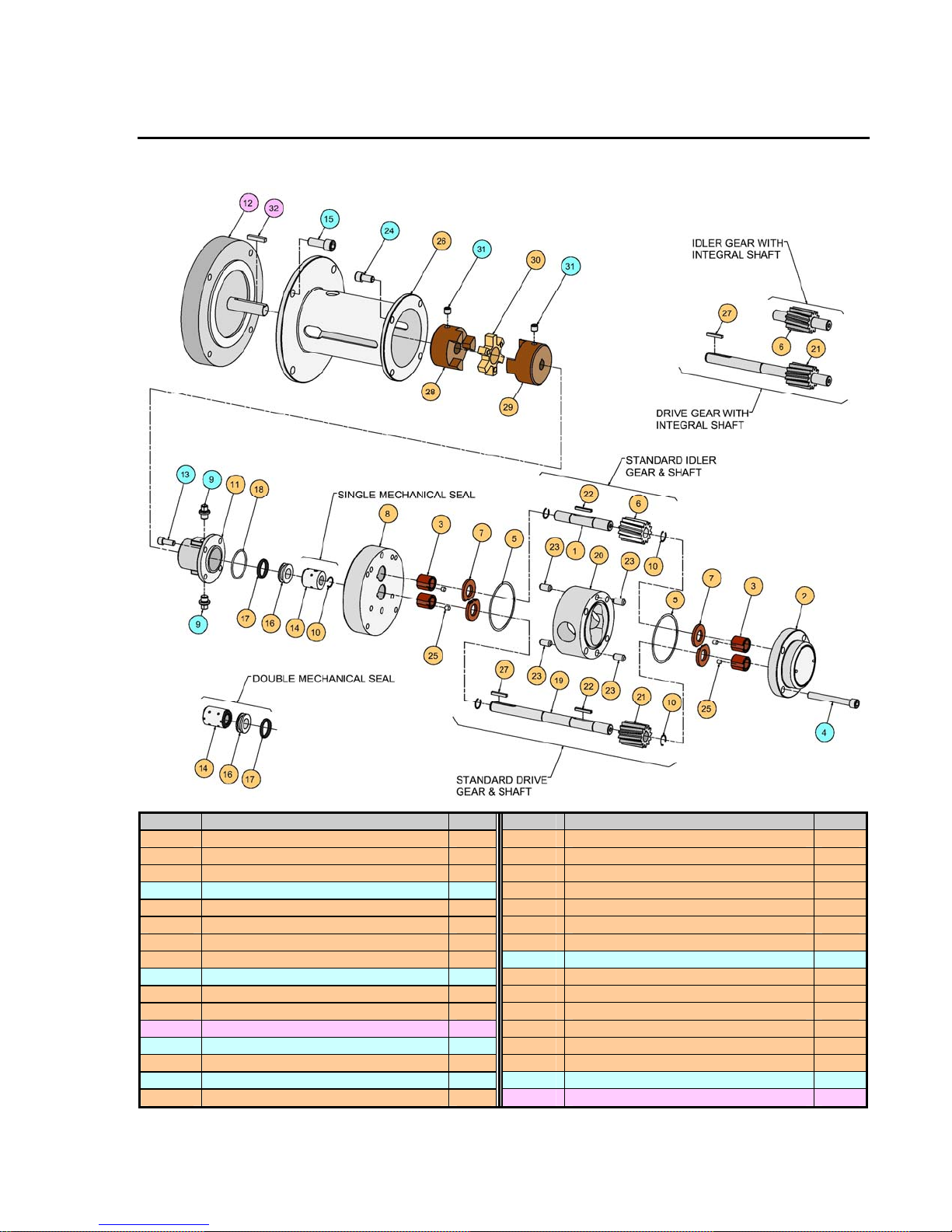
6. Exploded View Reference Drawings
Max® Series Sealed Pump – Models M2 thru M4
Item # Description Qty. Item # Description Qty.
1 Idler Shaft 1 17 O-rin g , Seal Seat 1 *
2 Rear Housing 1 18 O-ring, Seal Housing 1
3 Bearing 4 19 Drive Shaft 1
4 Bolt, Housing (5/16-18 SHCS) 4 20 Center Housing 1
5 O-ring, Housing 2 21 Drive Gear 1
6 Idler Gear 1 22 Key, Gear 2
7 Wear Plate 4 23 Pin, Housing Alignment 4
8 Front Housing 1 24 Bo lt, Frt. Hsg. (5/16-18 x 5/8 SHCS) 4
9 Plug, 1/8 NPT (Hex Socket) 2 25 Pin, Bearing Lock 4
10 Retaining Ring 5 * 26 Mounting Bracket 1
11 Seal Housing 1 27 Key, Coupling (Pump Side) 1
12 Motor (C-Face) 1 28 Coupling Flange (Motor Side) 1
13 Bolt, Seal Hsg. (1/4-28 x 5/8 SHCS) 4 29 Coupling Flange, 1/2” (Pump Side) 1
14 Mechanical Seal (Assembly) 1 30 Coupling Spider 1
15 Bolt, Motor (3/8-16 x 7/8 SHCS) 4 31 Setscrew, Coupling Flange 2
16 Seal Seat 1 * 32 Key, Motor 1
* Pump with Double Mechanical Seal requires 4 Retaining Rings, 2 Seal Seats and 2 Seal Seat O-rings.
12
Page 13
Liquiflo Installation, Operation & Maintenance Manual Max® Series Sealed Pumps
Models M2 thru M8
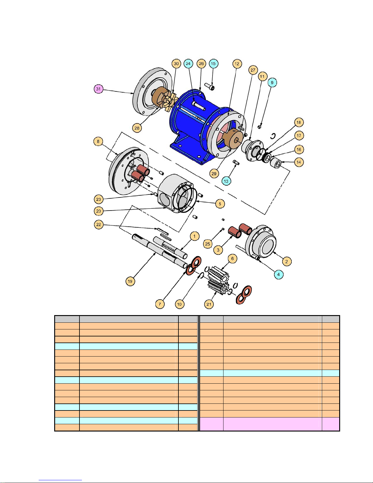
Exploded View of Max® Series Sealed Pump – Models M5 thru M8
Note: Pump is shown
with Standard Gears &
Shafts and Single Internal
Mechanical Seal.
Item # Description Qty. Item # Description Qty.
1 Idler Shaft 1 17 O-ring, Seal Seat 1 *
2 Rear Housing 1 18 O-ring, Seal Housing 1
3 Bearing 4 19 Drive Shaft 1
4 Bolt, Housing (5/16-18 SHCS) 8 20 Center Housing 1
5 O-ring, Housing 2 21 Drive Gear 1
6 Idler Gear 1 22 Key, Gear 2
7 Wear Plate 4 23 Pin, Housing Alignment 4
8 Front Housing 1 24 Bolt, Frt. Hsg. (3/8-16 x 1 5/8 SHCS) 4
9 Plug, 1/8 NPT (Hex Socket) 2 25 Pin, Bearing Lock 4
10 Retaining Ring 5 * 26 Pedestal 1
11 Seal Housing 1 27 Key, Coupling (Pump Side) 1
12 Adapter Ring 1 28 Coupling Flange (Motor Side) 1
13 Bolt, Seal Hsg. (1/4-28 x 5/8 SHCS) 4 29 Coupling Flange, 3/4” (Pump Side) 1
14 Mechanical Seal (Assembly) 1 30 Coupling Spider 1
15 Bolt, Motor (3/8-16 x 1 SHCS) 4
16 Seal Seat 1 *
* Pump with Double Mechanical Seal requires 4 Retaining Rings, 2 Seal Seats and 2 Seal Seat O-rings.
31 Motor (C-Face) with Key 1
13
Page 14
Liquiflo Installation, Operation & Maintenance Manual Max® Series Sealed Pumps
Models M2 thru M8
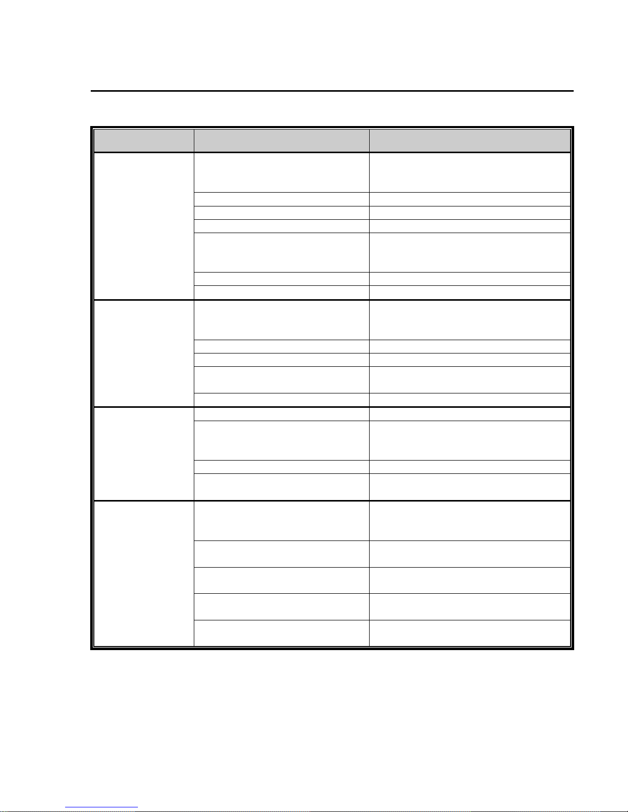
7: Troubleshooting Guide
Troubleshooting Guide - Part 1
Problem Possible Cause Corrective Action
Verify suction pipe is submerged.
No discharge
Insufficient
discharge
Loss of suction
after satisfactory
operation
Excessive power
consumption
Pump not primed
Wrong direction of rotation Reverse motor leads.
Valves closed Open all suction and discharge valves.
Bypass valve open Close bypass valve.
Air leak in suction line
Clogged strainer Clean strainer.
Pump worn or damaged Rebuild pump.
Suction pressure too low
Bypass valve open Close bypass valve.
Partly clogged strainer Clean strainer.
Speed too low
Pump worn or damaged Rebuild pump.
Pump not properly primed Reprime pump.
Air leaks in suction line
Air or vapor pockets in suction line Rearrange piping as necessary.
Increase in fluid viscosity
Fluid viscosity higher than specified
Differential pressure greater than
specified
Gear clearances insufficient for
fluid viscosity
Plastic gear clearance insufficient
for fluid temperature
Rotating parts binding or severely
worn
Increase suction pressure.
Open suction valve.
Tighten connections.
Apply sealant to all threads.
Verify suction pipe is submerged.
Increase suction pressure.
Verify suction piping is not too long.
Fully open any suction valves.
Increase driver speed, if possible.
Use larger size pump, if required.
Tighten connections.
Apply sealant to all threads.
Verify suction pipe is submerged.
Heat fluid to reduce viscosity.
Reduce pump speed.
Heat fluid to reduce viscosity.
Reduce pump speed.
Increase driver horsepower.
Increase pipe diameter.
Purchase gears trimmed for the correct
viscosity.
Purchase plastic gear trimmed for the
correct temperature.
Disassemble and replace worn parts.
14
Page 15
Liquiflo Installation, Operation & Maintenance Manual Max® Series Sealed Pumps
Models M2 thru M8
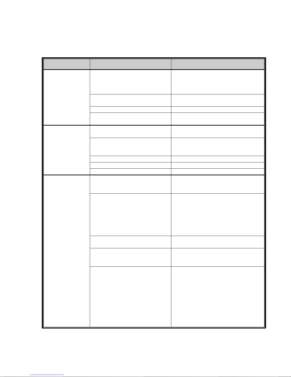
Troubleshooting Guide - Part 2
Problem Possible Cause Corrective Action
Install suction strainer.
Limit solids concentration.
Reduce pump speed or use larger pump
running at lower speed.
Use materials of construction that are
acceptable for fluid being pumped.
Increase pipe diameter.
Decrease pipe run.
Anchor per Hydraulic Institute Standards.
Tighten hold-down bolts on pump and
motor or adjust stilts.
Inspect grout and regrout if necessary.
Use O-rings or gaskets made of material
compatible with fluid and temperature of
the application.
Install O-rings or gaskets without twisting
or bending.
Use star-pattern torque sequence on
housing bolts during assembly.
Allow Teflon O-rings to cold flow and
seat during tightening.
Torque bolts to specification.
Disassemble and replace mechanical seal.
Prime pump and avoid dry running.
Use Teflon tape or other suitable sealant.
Use gaskets compatible with fluid and
temperature of the application.
Only pump chemical fluids that are
compatible with the pump housing
material.
Decrease temperature to reduce corrosion
rate to acceptable value.
Flush idle pumps that are used to pump
corrosive chemicals, such as acids and
caustics.
Eliminate contaminants in the fluid that
can accelerate corrosion wear.
Rapid pump wear
Excessive noise
and vibration
Excessive product
leakage
Abrasives in fluid
Corrosion wear
Extended dry running Install power sensor to stop pump.
Discharge pressure too high
Suction and/or discharge piping not
anchored or properly supported
Base not rigid enough
Worn pump bearings Replace bearings.
Worn motor bearings Replace bearings or motor.
Pump cavitation Increase NPSH available.
Static seal failure caused by
chemical incompatibility or thermal
breakdown
Static seal failure caused by
improper installation
Mechanical seal worn or damaged
Pump port connections not properly
sealed
Crevice corrosion of pump housing
material
15
Page 16
-- 0.3
E
0..
0)
--
(])
+-'
co
I....
3:
0
u.. 0.2
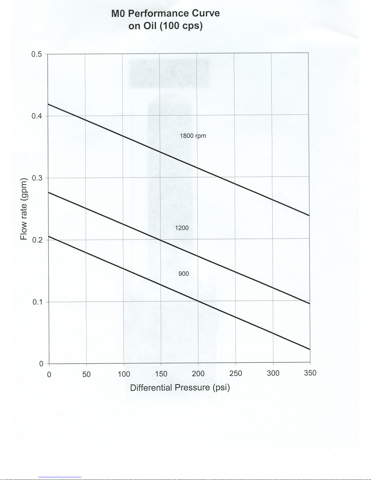
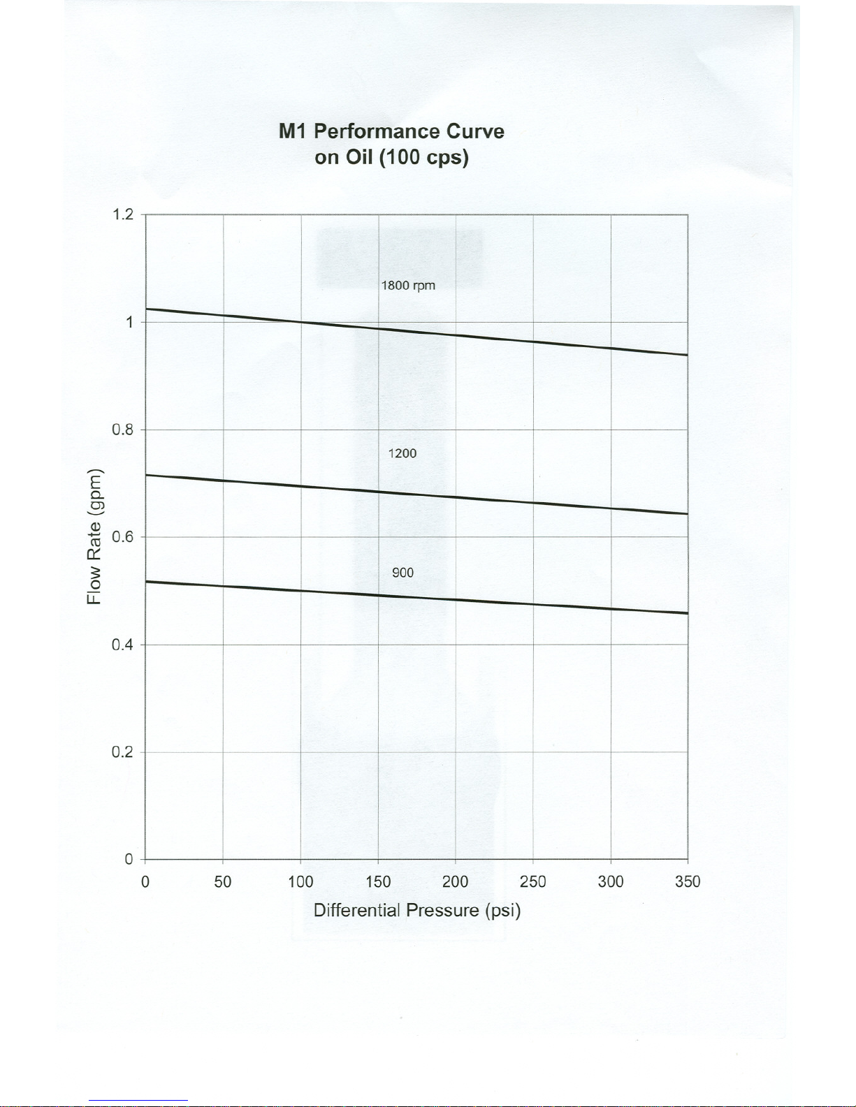
MOPerformance Curve
on Oil (100 cps)
0.5
0.4
1800 npm
1200
0.1
0
0 50
100 150 200 250
Differential Pressure (psi)
300 350
Page 17
..-
E
0..
0>
'-"
Q)
ro 0.6
0::
~
0
LL
M1 Performance Curve
on Oil (100 cps)
1.2
1
0.8
0.4
0.2
0
0
100 150 200 250
Differential Pressure (psi)
300 350
50
1800rpm
1200
900
Page 18
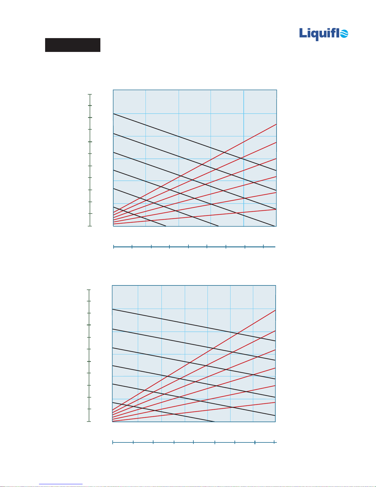
MAX®-SERIES PERFORMANCE DATA
Model M2
TM
1 cP Fluid (Water)
LPM
11
10
9
3.0
2.5
1800
0.6
0.5
10
11
9
8
7
6
5
4
3
2
1
0
LPM
1500
2.0
1200
1.5
900
FLOW (GPM)
1.0
600
0.5
300
0
0
0
100 cP Fluid (Oil)
3.0
1800
2.5
1800
0.4
0.3
POWER (BHP)
0.2
0.1
300
25
DIFFERENTIAL PRESSURE (PSI)
2
4
7550
100
6
0
125
BAR
8
1.50
1800
1.25
8
7
6
5
4
3
2
1
0
1500
2.0
1200
1.5
900
FLOW (GPM)
1.0
600
0.5
300
0
0
0
1.00
0.75
POWER (BHP)
0.50
0.25
300
50
6
150100
DIFFERENTIAL PRESSURE (PSI)
200
12
250
300
18
350
24
0
BAR
Page 19
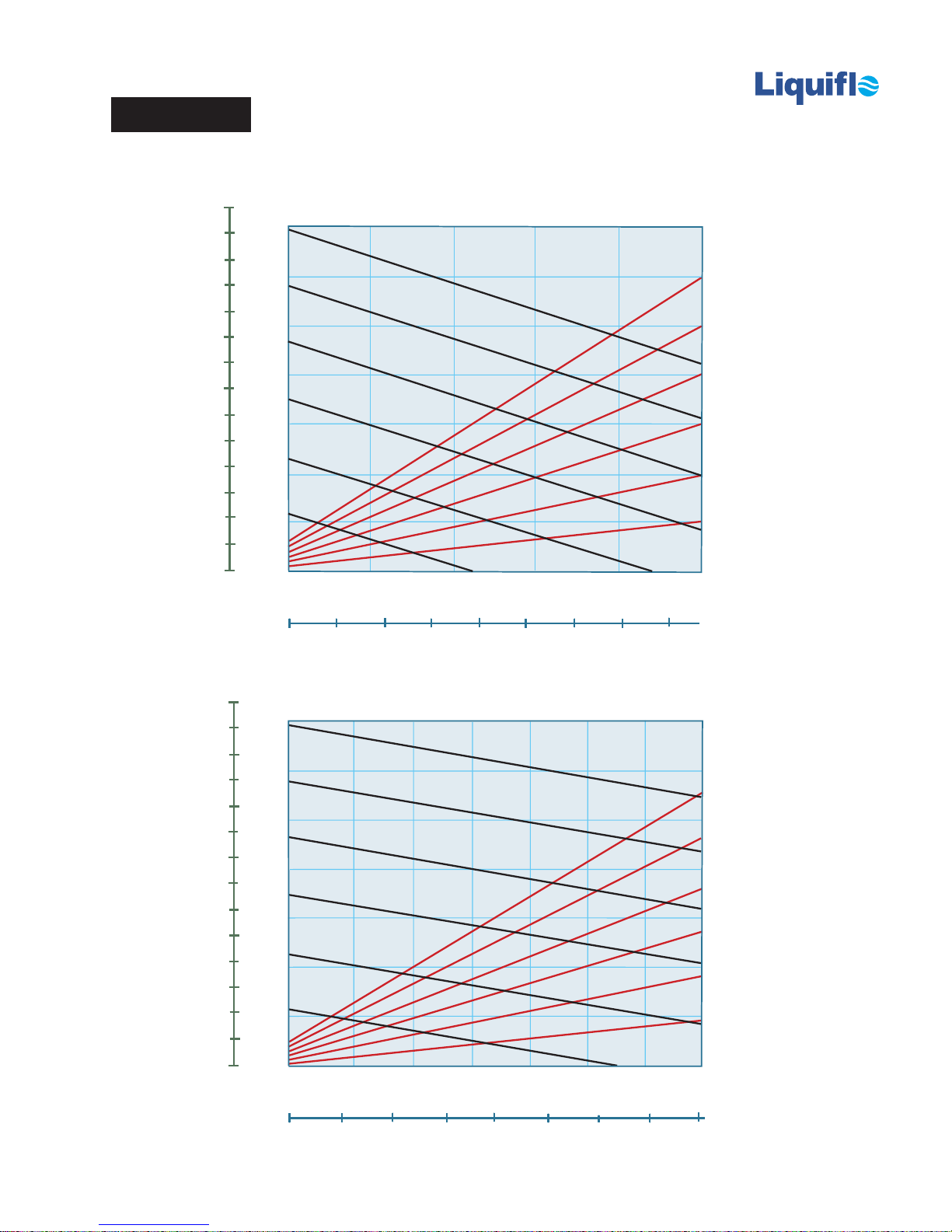
MAX®-SERIES PERFORMANCE DATA
Model M3
TM
14
13
12
11
10
9
8
7
6
5
4
3
2
1
0
LPM
1 cP Fluid (Water)
3.5
3.0
2.5
2.0
1.5
FLOW (GPM)
1.0
0.5
0
1800
1500
1200
900
600
300
0
0
0.7
0.6
1800
0.5
0.4
0.3
POWER (BHP)
0.2
0.1
300
25
DIFFERENTIAL PRESSURE (PSI)
2
4
7550
100
6
0
125
BAR
8
14
13
12
11
10
9
8
7
6
5
4
3
2
1
0
LPM
100 cP Fluid (Oil)
3.5
3.0
1500
2.5
1200
2.0
900
1.5
FLOW (GPM)
600
1.0
300
0.5
0
0
0
1800
50
150100
DIFFERENTIAL PRESSURE (PSI)
6
12
200
250
2.1
1.8
1800
1.5
1.2
0.9
POWER (BHP)
0.6
0.3
300
300
18
350
24
0
BAR
Page 20
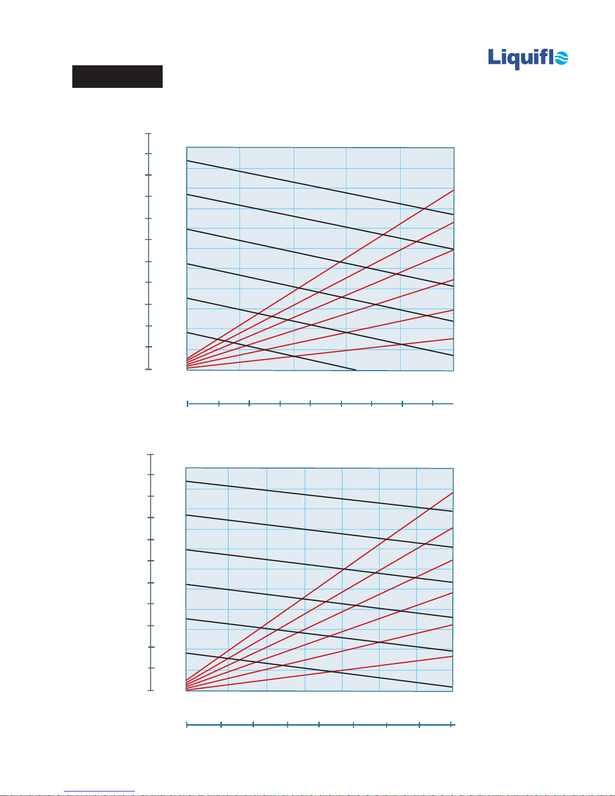
MAX®-SERIES PERFORMANCE DATA
Model M4
TM
LPM
22
20
18
16
14
12
10
8
6
4
2
0
1 cP Fluid (Water)
5.5
1800
5.0
4.5
1500
4.0
1200
3.5
3.0
900
2.5
FLOW (GPM)
2.0
600
1.5
1.0
300
0.5
0
0
0
1.1
1.0
1800
0.9
0.8
0.7
0.6
0.5
POWER (BHP)
0.4
0.3
300
0.2
0.1
25
DIFFERENTIAL PRESSURE (PSI)
2
4
7550
100
6
0
125
BAR
8
22
20
18
16
14
12
10
4
2
0
8
6
LPM
100 cP Fluid (Oil)
5.5
1800
5.0
4.5
1500
4.0
1200
3.5
3.0
900
2.5
FLOW (GPM)
2.0
600
1.5
300
1.0
0.5
0
0
0
50
150100
DIFFERENTIAL PRESSURE (PSI)
6
12
200
250
2.75
2.50
1800
2.25
2.00
1.75
1.50
1.25
POWER (BHP)
1.00
0.75
0.50
300
0.25
300
18
350
24
0
BAR
Page 21
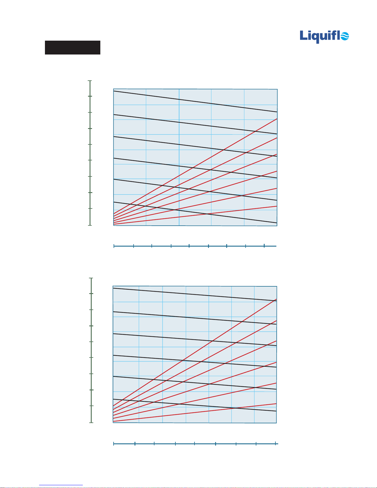
MAX®-SERIES PERFORMANCE DATA
Model M5
TM
36
32
28
24
20
16
12
8
4
0
LPM
1 cP Fluid (Water)
9
1800
8
1500
7
6
1200
5
900
4
FLOW (GPM)
3
600
2
300
1
0
0
0
1.8
1.6
1800
1.4
1.2
1.0
0.8
POWER (BHP)
0.6
0.4
300
25
DIFFERENTIAL PRESSURE (PSI)
2
4
7550
100
6
0.2
0
125
BAR
8
36
32
28
24
20
16
12
8
4
0
LPM
100 cP Fluid (Oil)
9
1800
8
1500
7
6
1200
5
900
4
FLOW (GPM)
3
600
2
300
1
0
0
0
50
150100
DIFFERENTIAL PRESSURE (PSI)
6
12
200
250
4.5
4.0
1800
3.5
3.0
2.5
2.0
1.5
1.0
300
0.5
0
300
18
350
BAR
24
Page 22
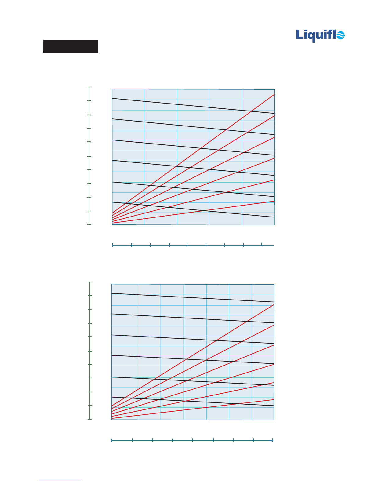
MAX®-SERIES PERFORMANCE DATA
Model M6
TM
50
45
40
35
30
25
20
15
10
5
0
LPM
1 cP Fluid (Water)
13
1800
12
11
1500
10
9
1200
8
7
900
6
FLOW (GPM)
5
600
4
3
300
2
1
0
0
0
1.95
1800
1.80
1.65
1.50
1.35
1.20
1.05
0.90
POWER (BHP)
0.75
0.60
0.45
300
0.30
0.15
0
25
DIFFERENTIAL PRESSURE (PSI)
2
4
7550
100
6
125
BAR
8
LPM
50
45
40
35
30
25
20
15
10
5
0
100 cP Fluid (Oil)
13
1800
12
11
1500
10
9
1200
8
7
900
6
FLOW (GPM)
5
600
4
3
300
2
1
0
0
0
50
150100
DIFFERENTIAL PRESSURE (PSI)
6
12
200
250
6.5
6.0
5.5
1800
5.0
4.5
4.0
3.5
3.0
POWER (BHP)
2.5
2.0
1.5
300
1.0
0.5
0
300
18
350
BAR
24
Page 23
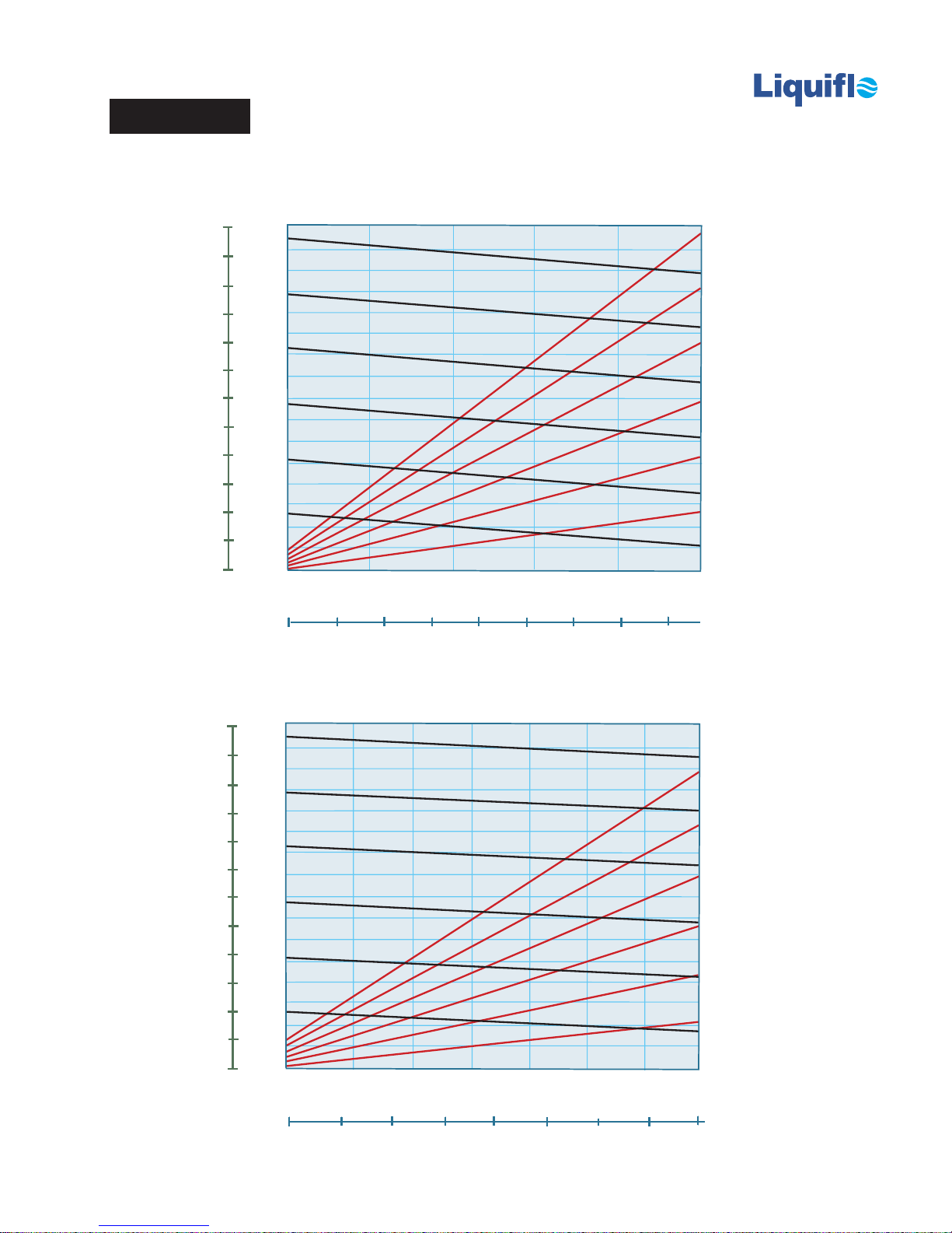
MAX®-SERIES PERFORMANCE DATA
Model M7
TM
LPM
60
55
16
1800
15
1800
14
50
45
40
1500
13
12
11
1200
10
35
30
25
9
900
8
7
FLOW (GPM)
6
20
15
10
600
5
4
3
300
2
5
0
1
0
0
0
25
2
50
DIFFERENTIAL PRESSURE (PSI)
4
75
100
6
300
8
125
2.40
2.25
2.10
1.95
1.80
1.65
1.50
1.35
1.20
1.05
0.90
0.75
0.60
0.45
0.30
0.15
0
BAR
POWER (BHP)
1 cP Fluid (Water)
LPM
60
55
50
45
40
35
30
25
20
15
10
5
0
100 cP Fluid (Oil)
16
1800
15
14
1500
13
12
11
1200
10
9
900
8
7
FLOW (GPM)
6
600
5
4
3
300
2
1
0
0
0
50
150100
DIFFERENTIAL PRESSURE (PSI)
6
12
200
250
8.0
7.5
1800
7.0
6.5
6.0
5.5
5.0
4.5
4.0
3.5
POWER (BHP)
3.0
2.5
2.0
1.5
300
1.0
0.5
300
18
350
24
0
BAR
Page 24
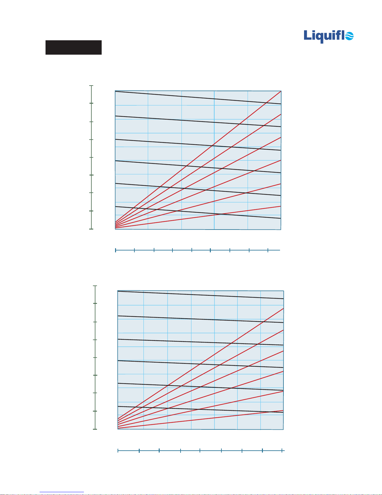
MAX®-SERIES PERFORMANCE DATA
Model M8
TM
LPM
80
70
1 cP Fluid (Water)
20
1800
18
1800
3.0
2.7
1500
60
50
16
14
1200
12
40
30
900
10
FLOW (GPM)
8
2.4
2.1
1.8
1.5
1.2
POWER (BHP)
600
300
8
125
0.9
0.6
0.3
0
BAR
20
10
6
4
300
2
0
0
0
0
25
2
50
DIFFERENTIAL PRESSURE (PSI)
4
75
100
6
80
70
60
50
40
30
20
10
0
LPM
100 cP Fluid (Oil)
20
1800
18
1500
16
14
1200
12
900
10
FLOW (GPM)
8
600
6
4
300
2
0
0
0
50
150100
DIFFERENTIAL PRESSURE (PSI)
6
12
200
250
10
9
1800
8
7
6
5
POWER (BHP)
4
3
2
300
1
300
18
350
24
0
BAR
 Loading...