

Page 1

TME-EPIC-HURQM-R2V4.docx
Revision 2.4 / July 11
© LIPPERT Embedded Computers GmbH
Hans-Thoma-Str. 11
D-68163 Mannheim
http://www.lippertembedded.com/
Hurricane-QM57
EPIC Express Single Board Computer
Technical Manual
Page 2

TME-EPIC-HURQM-R2V4.docx Revision 2.4
Technical Manual Hurricane-QM57
LiPPERT Document: TME-EPIC-HURQM-R2V4.docx Revision 2.4
Copyright ©2011 LiPP ERT Embedded Computers GmbH , All rights reserved
Trademarks
MS-DOS, Windows, Windows 95, W in dows 98, Windows NT and Windows XP are tradem a rks of
Microsoft Corporation. PS/2 is a trademark of International Bu s iness Machines , Inc. Intel and Solid
State Drive are trademarks of Intel C or p or a tion. Geode is a tr a de m a rk of Advanced Mic ro Devices.
PC/104 is a registered trademark of PC/104 Consortium . All other trademarks appearing in this
document are the property of their respective owners.
Disclaimer
Contents and spec ifications with in this technical manual are subject of change without notic e.
LiPPERT Embedded Computers G m bH provides no warranty w ith r ega rd to this technical manual or
any other infor m a tion contained herein and hereby expressly disclaims any implied warranties of
merchantability or fitness for any particular purpos e with regard to any of the foregoing. LiP P ERT
Embedded Computers GmbH as s umes no liability for a ny damages incurr e d d ir ectly or indirectly
from any technic a l or typographical errors or omissions con ta ined herein or for discr ep a ncies
between the product and the tec hnical manual. In no event sh a ll LiP P ERT Embedded Computers
GmbH be liable for any incidental, con s equential, special, or ex em plar y damages, whether based on
tort, contract or otherwise, arising out of or in connection with this user ’s guide or any othe r
information conta ined herein or the use thereof.
.
Page 3

TME-EPIC-HURQM-R2V4.docx Revision 2.4 i
Table of Contents
1 Overview 1
1.1 Introduction ............................................................................................... 1
Features
.................................................................................................... 1
Block Diagram
............................................................................................. 2
1.2 Ordering Information .................................................................................... 3
Hurricane-QM57 Models
................................................................................ 3
Cable Sets and Accessories
............................................................................ 3
1.3 Specifications ............................................................................................. 4
Electrical Specifications
................................................................................. 4
Environmental Specifications
........................................................................... 4
Mean Time Between Failures
........................................................................... 4
1.4 Mechanical ................................................................................................ 5
2 Getting Started 6
2.1 Connector Locations .................................................................................... 6
Top
.......................................................................................................... 6
Bottom
...................................................................................................... 7
2.2 Jumper Locations ........................................................................................ 8
2.3 LED indicators ............................................................................................ 9
2.4 Hardware Setup .......................................................................................... 10
3 Module Description 11
3.1 Processor ................................................................................................. 11
3.2 Platform Controller Hub (PCH) ......................................................................... 11
3.3 Graphics-Controller ...................................................................................... 12
DisplayPort (DP) Connector (X2, X3)
.................................................................. 12
LVDS Configuration
...................................................................................... 12
LVDS Connector (X27)
.................................................................................. 13
LVDS Color Mapping
.................................................................................... 14
Display Backlight Connector (X25)
.................................................................... 14
Display Voltage Selector (X11)
......................................................................... 14
3.4 Gigabit Ethernet Controller ............................................................................. 15
Page 4

TME-EPIC-HURQM-R2V4.docx Revision 2.4 ii
Ethernet Connector (X8, X29) .......................................................................... 15
3.5 USB 2.0 Ports ............................................................................................ 16
USB Connectors (0-3 & 8-9, exemplary described USB 0/1, X12, X13, X14)
................. 16
USB Connectors (4-7, exemplary described USB 4/5, X28, X31)
............................... 16
3.6 Serial ATA Ports .......................................................................................... 17
SATA Connector (X15, X16, X17, X19)
............................................................... 17
3.7 Audio ....................................................................................................... 17
Audio Connector (X10)
.................................................................................. 18
3.8 PCI/104-Express Bus Interface ........................................................................ 18
PCI/104-Express Connector (X18)
.................................................................... 19
3.9 PC/104-Plus Bus Interface ............................................................................. 21
PC/104-Plus Connector (X32)
......................................................................... 22
3.10 PCIe Mini-Card (X9) ..................................................................................... 23
3.11 On Board Power Supply ................................................................................ 24
Power Connector (X26)
................................................................................. 24
Real Time Clock Backup
............................................................................... 24
3.12 System Panel Connector (X5) .......................................................................... 25
SMBus/I²C
................................................................................................ 25
Power-Button
............................................................................................. 25
Reset-Button
............................................................................................. 26
HDD-LED
.................................................................................................. 26
Watchdog
................................................................................................. 26
Power-LED
................................................................................................ 27
GPIO’s
..................................................................................................... 27
3.13 Backup BIOS ............................................................................................. 27
Backup BIOS Connector (X24)
........................................................................ 27
3.14 LPC Bus ................................................................................................... 28
LPC Connector (X4)
..................................................................................... 28
3.15 LEMT functions ........................................................................................... 28
Board Specific LEMT functions
........................................................................ 29
3.16 CPU Fan Connector (X20) .............................................................................. 31
3.17 Chassis Fan Supply (X21) .............................................................................. 31
4 Using the Module 32
Page 5

TME-EPIC-HURQM-R2V4.docx Revision 2.4 iii
4.1 BIOS ........................................................................................................ 32
Configuring the Phoenix BIOS
......................................................................... 32
Initialize BIOS at first startup
........................................................................... 32
Booting from alternative device
....................................................................... 32
EFI Shell
................................................................................................... 33
Jumper BIOS Defaults
.................................................................................. 33
BIOS Screens
............................................................................................. 34
Phoenix – SecureCore BIOS - Main 34
Phoenix – SecureCore BIOS – Main – System Information 34
Advanced 35
Advanced – Boot Configuration
35
Advanced – ACPI Configuration 36
Advanced – Processor Configuration 36
Advanced – Process or Configuration – Processor Power Management 37
Advanced – Peripher al Configuration 37
Advanced – HDD Configuration 38
Advanced – IMC Configuration 38
Advanced – IMC Configuration – NB Common Configuration
39
Advanced – IMC Configuration – NB Common Configuration – VT for Directed I/O 39
Advanced – IMC Configuration – NB Common Configuration – Video Configuration 40
Advanced – IMC Configuration – Arrandale Config 40
Advanced – IMC Configuration – Arrandale Config – PE G Configuration 41
Advanced – IMC Configuration – Arrandale Config – IGD Config 41
Advanced – IMC Configuration – Arrandale Config – IGD Config – Boot Type
42
Advanced – IMC Configuration – Arrandale Config – IGD Config – Panel Type 42
Advanced – South Br id ge Config 43
Advanced – South Br id ge Config – SB PCI Express Config 43
Advanced – South Br id ge Config – SB PCI Express Config – PCI Express Root Port1 44
Advanced – Network Configuration 44
Advanced – SMBIOS Event Log 45
Advanced – ME Configuration
45
Advanced – Thermal Configuration 46
Advanced – Thermal Configuration – Processor Thermal Management Submenu 46
Advanced – Thermal Configuration – Intelligent Power Sharing 47
Advanced – Thermal Configuration – Platform Thermal Configuration 47
Security 48
Boot 48
Exit
49
4.2 Drivers ..................................................................................................... 49
Page 6

TME-EPIC-HURQM-R2V4.docx Revision 2.4 iv
5 Address Maps 50
5.1 Memory Address Map .................................................................................. 50
5.2 I/O Address Map ......................................................................................... 51
5.3 Interrupts .................................................................................................. 53
5.4 DMA Channels ............................................................................................ 53
6 Troubleshooting 54
Contact Information A
Getting Help B
Additional Information C
Revision History D
Page 7

TME-EPIC-HURQM-R2V4.docx Revision 2.4 Page 1 of 54
1 Overview
1.1 Introduction
The Hurricane-QM57 offers a high performance EPIC board with the i7-620UE, i7-610E and Celeron P4505
Processor Series from Intel
®
Two Ethernet GbE ports, six USB 2.0 host ports and two Power-USB 2.0 host ports handle the communication
with external devices. Four SATA ports allow connection of hard disk or CD drives.
Core™. This processor is a next generation of 64-bit, multi-core mobile processor
built on 32-nanometer process technology. Based on the low-power/high-performance Nehalem microarchitecture, the Arrandale processor is designed for a two-chip platform as opposed to the traditional three-chip
platforms (processor, GMCH, and ICH). The two-chip platform consists of a processor and the Platform Controller
Hub (PCH) and enables higher performance, lower cost and easier validation. In this case the PCH is Intel’s Ibex
Peak-M (Mobile Intel® 5 Series Chipset).
System expansion can easily be realized over PCI/104-Express, PC/104-Plus, I²C bus and Mini-PCI connectors.
The Hurricane-QM57 runs DOS, Windows and Linux operating systems.
Features
• Intel Arrandale™
CPU
• Cache Memory with:
• 32 KB/32 KB level 1 I/D caches
• 256 KB level 2 I/D cache
•
Up to 4 MB level 3 I/D cache
• soldered 1GB DDR3 RAM
Main Memory
• Intel® 5 Series Chipset (formerly Ibex Peak-M)
Chipset
• 1 x PC/104-Plus Bus
Extension slots
•
1 x PCI/104Express Bus
• 4 x SATA
Interfaces
• 6 x USB 2.0 ports
• 2 x Power-USB 2.0 ports
• 2 x Ethernet GbE
• SPDIF Out
• 7.1 Audio
•
MiniPCI-Express
• DisplayPort
• 18/24 Bit LVDS for displays
• MISC signals: external power button, external reset
button, I²C bus, GPIO’s, external HDD and Power
LED, LPC
• Power supply
• Lippert Enhanced Management Technology (LEMT)
Other configurations are possible. Please contact your local LiPPERT representative to discuss requirements.
Page 8

TME-EPIC-HURQM-R2V4.docx Revision 2.4 Page 2 of 54
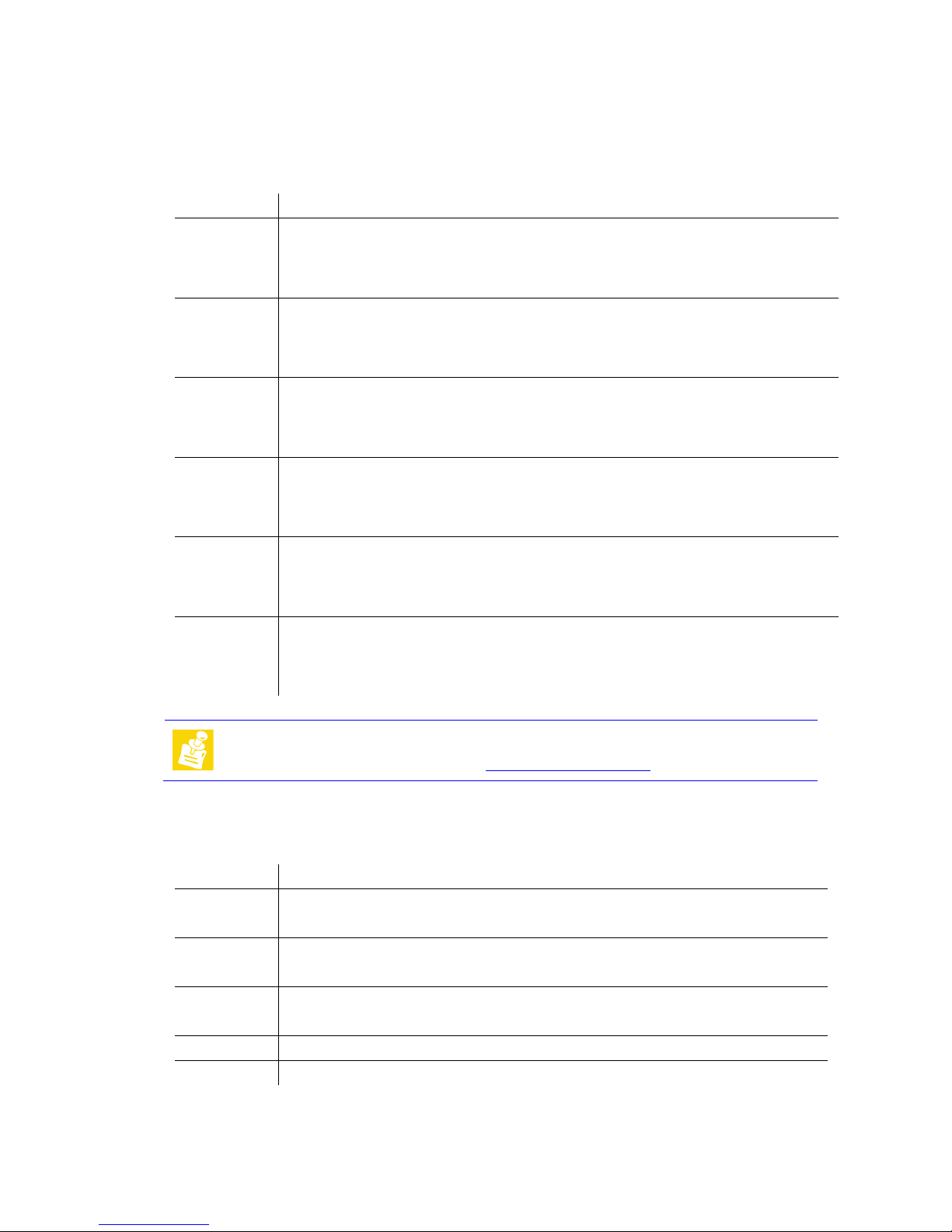
Block Diagram
Page 9
TME-EPIC-HURQM-R2V4.docx Revision 2.4 Page 3 of 54
1.2 Ordering Information
Hurricane-QM57 Models
Order number
Description
714-0006-10 Hurricane-QM57 with Intel i7-620UE, 1.06 GHz, low power consumption, 2 GB DDR3 RAM
onboard, 8x USB2.0, 2x POWER-USB2.0, SPDIF Out, 7.1 Audio, 4x SATA, SMC, PCI/104Express bus, PC/104+ bus, DisplayPort, LVDS Interface, 2x Ethernet GbE, LPC.
Operating temp. range: -0°C…+60°C
814-0006-10 Hurricane-QM57 with Intel i7-620UE, 1.06 GHz, low power consumption, 2 GB DDR3 RAM
onboard, 8x USB2.0, 2x POWER-USB2.0, SPDIF Out, 7.1 Audio, 4x SATA, SMC, PCI/104Express bus, PC/104+ bus, DisplayPort, LVDS Interface, 2x Ethernet GbE, LPC.
Operating temp. range: -20°C…+60°C
914-0006-10 Hurricane-QM57 with Intel i7-620UE, 1.06 GHz, low power consumption, 2 GB DDR3 RAM
onboard, 8x USB2.0, 2x POWER-USB2.0, SPDIF Out, 7.1 Audio, 4x SATA, SMC, PCI/104Express bus, PC/104+ bus, DisplayPort, LVDS Interface, 2x Ethernet GbE, LPC.
Operating temp. range: -40°C…+85°C
714-0007-10
Hurricane-QM57 with Intel i7-610E, 2.53 GHz, low power consumption, 2 GB DDR3 RAM
onboard, 8x USB2.0, 2x POWER-USB2.0, SPDIF Out, 7.1 Audio, 4x SATA, SMC, PCI/104Express bus, PC/104+ bus, DisplayPort, LVDS Interface, 2x Ethernet GbE, LPC.
Operating temp. range: 0°C…+60°C
814-0007-10 Hurricane-QM57 with Intel i7-610E, 2.53 GHz, low power consumption, 2 GB DDR3 RAM
onboard, 8x USB2.0, 2x POWER-USB2.0, SPDIF Out, 7.1 Audio, 4x SATA, SMC, PCI/104Express bus, PC/104+ bus, DisplayPort, LVDS Interface, 2x Ethernet GbE, LPC.
Operating temp. range: -20°C…+60°C
914-0007-10 Hurricane-QM57 with Intel i7-610E, 2.53 GHz, low power consumption, 2 GB DDR3 RAM
onboard, 8x USB2.0, 2x POWER-USB2.0, SPDIF Out, 7.1 Audio, 4x SATA, SMC, PCI/104Express bus, PC/104+ bus, DisplayPort, LVDS Interface, 2x Ethernet GbE, LPC.
Operating temp. range: -40°C…+85°C
Note:
Custom combinations of processor and memory are possible.
Minimum order quantities are required.
Contact LiPPERT’s Sales Team at
Cable Sets and Accessories
There are some options available for the Hurricane-QM57. Please check their availability before ordering.
Order number
Description
760-0027-10 RAM, unbuffered ECC, RSOMM, REVERSE, 2GB
Operating temp. range: -0°C…+60°C
860-0027-10 RAM, unbuffered ECC, RSOMM, REVERSE, 2GB
Operating temp. range: -20°C…+60°C
960-0027-10 RAM, unbuffered ECC, RSOMM, REVERSE, 2GB
Operating temp. range: -40°C…+85°C
862-0058-10 Cable, DF13-8S (1,25mm) to 2x USB (A)
862-0065-10 Cable, IDC16 (2mm) to 5x audio female, 2x cinch female, 200mm length
Page 10

TME-EPIC-HURQM-R2V4.docx Revision 2.4 Page 4 of 54
1.3 Specifications
Electrical Specifications
Supply voltage ATX power supply with 5V, 5V always, 3.3 volt. 12 volt DC
Rise time
< 10 ms
Supply voltage tolerance ± 5% *
Inrush current +5VSB: 1.0A
+5V: 0.5A
+3.3V: 0.2A
+12V: 2.5A
Supply current maximum** typical (idle) typical (S3)
+5VSB
0.14
0.14
0.22
+5V 0.10 0.10 -
+3.3V 0.12 0.12 -
+12V
3.11
1.31
-
* With that tolerance it is not mentioned that all plugged devices are running with.
** That rate of current is possible when only monitor, mouse and keyboard are plugged.
The current increases if additional peripheral devices are connected.
Environmental Specifications
Operating:
Temperature range 0 … 60 °C (standard version)
-20 … 60 °C (industrial version)
Temperature change max. 10K / 30 minutes
Humidity (relative) 10 … 90 % (non-condensing)
Pressure 450 … 1100 hPa
Non-Operating/Storage/Transport:
Temperature range -40 … 85 °C
Temperature change max. 10K / 30 minutes
Humidity (relative) 5 … 95 % (non-condensing)
Pressure 450 … 1100 hPa
Mean Time Between Failures
MTBF at 25°C 128,820 hours
Page 11

TME-EPIC-HURQM-R2V4.docx Revision 2.4 Page 5 of 54
1.4 Mechanical
Dimensions (L x W) 165 mm x 115 mm
Height max. 40 mm on top side above PCB
max. 12 mm on bottom side above PCB
Weight 275 g
Mounting
4 mounting holes for PCB
4 mounting holes for PCI/104-Express/PC104+ extension cards
Note
It is strongly recommend using plastic spacers instead of metal spacers to mount
the board. With metal spacers, there is a possible danger to create a short circuit
with the components located around the mounting holes.
This can damage the board!
Page 12

TME-EPIC-HURQM-R2V4.docx Revision 2.4 Page 6 of 54
2 Getting Started
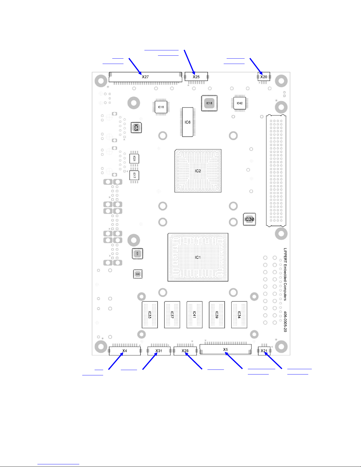
2.1 Connector Locations
Top
The pin 1 of the connectors is marked
Serial ATA
Port 0
X15
Serial ATA
Port 1
X16
Serial ATA
Port 2
X17
Serial ATA
Port 3
X19
HD Audio
X10
SMC-Service
Connector
X30
SPDIF
X1
GBit Ethernet
X29
GBit Ethernet
X8
2 x Power USB
Port 8/9
X14
2 x USB
Port 2/3
X13
2 x USB
Port 0/1
X12
DisplayPort
Port D
X3
DisplayPort
Port C
X2
PCI/104-Express
Bus Interface
X18
PC/104-Plus
Bus Interface
X32
Power
Connector
X26
RSOMM
Connector
X6
Backup BIOS
Connector
X24
Mini PCI Express
X9A
Page 13
TME-EPIC-HURQM-R2V4.docx Revision 2.4 Page 7 of 54
Bottom
The pin 1 of the connectors is marked
LVDS
Connector
X27
Display Backlight
Connector
X25
CPU Fan
Connector
X20
Chassis Fan
Connector
X21
LPC
Connector
X4
2 x USB
Port 6/7
X31
2 x USB
Port 4/5
X28
System Panel
Connector
X5
Page 14

TME-EPIC-HURQM-R2V4.docx Revision 2.4 Page 8 of 54
2.2 Jumper Locations
Jumper CMOS
X22
Jumper Display Voltage
Selector
X11
Page 15
TME-EPIC-HURQM-R2V4.docx Revision 2.4 Page 9 of 54
2.3 LED indicators
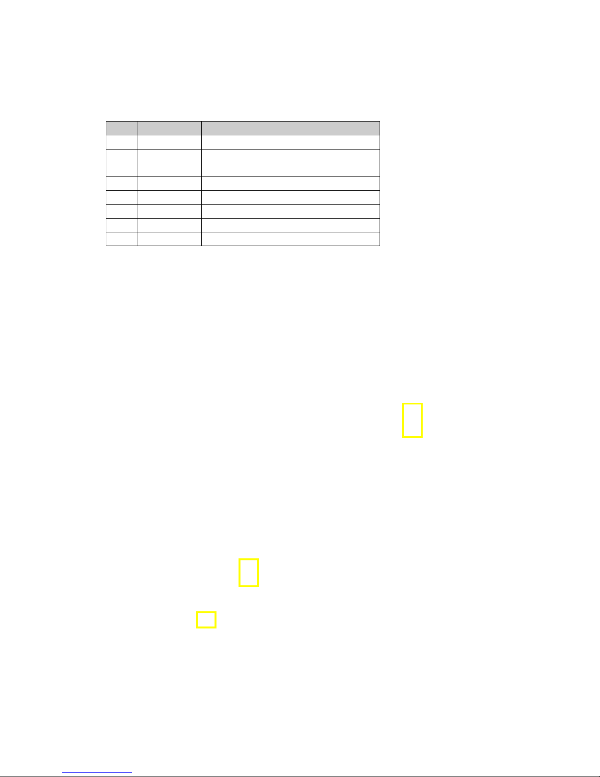
To facilitate problem solving, the Hurricane-QM57 provides LED indicators for the following conditions:
LED Name Function
1 WD Watchdog activated
2 STB
Standby Power Supply
3 POM
Power Mode
4 MP Main Power Supply
5 SATA
SATA accesses (Hard Disk Drive)
6 WAN
Status of wireless add-in card (WAN)
7 LAN
Status of wireless add-in card (LAN)
8 PAN
Status of wireless add-in card (PAN)
6
7
8
5
1
2
3
Page 16

TME-EPIC-HURQM-R2V4.docx Revision 2.4 Page 10 of 54
2.4 Hardware Setup
Installing the Hurricane-QM57 is very straightforward. First, unpack the board observing the usual electrostatic
discharge (ESD) precautions.
Caution
Before you touch the board, make sure that you have discharged yourself and your
gear towards a grounded terminal. Damages due to ESD are usually not immediately
visible and will only show up later as failures in the field.
Mount the cooling device.
Caution
Never operate the Hurricane-QM57 without suitable cooling devices. Failing this can
destroy the module.
Caution
Never connect or disconnect peripherals like hard drives while the board's power
supply is connected and switched on!
Connect the Hurricane-QM57 to a DisplayPort monitor. Connect USB keyboard or mouse, respectively. Connect a
hard drive with a SATA cable to start an operation system. Make sure that the pins match their counterparts
correctly and are not twisted! If you plan to use additional other peripherals, now is the time to connect them, too.
Connect a standard ATX power supply to the power connector and switch the power on.
Note
The ampere values in chapter 1.3 are the minimum you should have for the standard
peripherals mentioned. If you want to use more and/or others, please plan your
power budget first! The system will not work if there is not enough supply current for
all your devices.
The display shows the BIOS messages. If you want to change the standard BIOS settings, press the <F2> key to
enter the BIOS menu. See chapter 4 for setup details.
If you need to load the BIOS default values, the jumper “CMOS” have to be plugged during startup. This forces the
BIOS to load the factory settings from Flash.
The Hurricane-QM57 boots from CD drives, USB floppy, USB stick, hard disk or network. Provided that any of
these is connected and contains a valid operating system image, the display then shows the boot screen of your
operating system.
Note
Not all USB devices are suitable to boot the Hurricane-QM57. If there are problems,
please try to use another device from another manufacturer.
Page 17

TME-EPIC-HURQM-R2V4.docx Revision 2.4 Page 11 of 54
3 Module Description
3.1 Processor
Intel Core i7-620UE, i7-610E and Celeron P4505 Processor Series is the next generation of 64-bit, multi-core
mobile processor built on a 32- nanometer process technology. Throughout this document, Intel
®
CoreTM i7-620UE,
i7-610E and Celeron P4505 Processor Series may be referred to as simply the processor. The processor is
designed for a two-chip platform as opposed to the traditional three-chip platforms (processor, GMCH, and ICH).
The two-chip platform consists of a processor and the Platform Controller Hub (PCH) and enables higher
performance, lower cost, easier validation, and improved x-y footprint. The PCH may also be referred to as Mobile
Intel® 5 Series Chipset (formerly Ibex Peak-M). Intel
®
CoreTM i7-620UE, i7-610E and Celeron P4505 Processor
Series is designed for the Intel
®
Core
TM
Included in this family of processors is an integrated graphics and memory controller die on the same package as
the processor core die. This two-chip solution of a processor core die with an integrated graphics and memory
controller die is known as a multi-chip package (MCP) processor.
i7 processor based low-power platform and is offered in a BGA1288
package.
Processor feature details:
• Two execution cores
• A 32-KB instruction and 32-KB data first-level cache (L1) for each core
• A 256-KB shared instruction/data second-level cache (L2) for each core
• Up to 4-MB shared instruction/data third-level cache (L3), shared among all cores
Interfaces:
• System Memory Support
• dual-channel memory organization mode
• Memory DDR3 data transfer rate of 1066 MT/s
• 1-Gb, and 2-Gb DDR3 DRAM technologies for x16 devices
• PCI Express*
• The processor PCI Express* port(s) are fully-compliant to the PCI Express Base Specification, Revision
2.0 at 2.5GT/s.
• The processor supports:
- One 16-lane PCI Express port for graphics or I/O.
- Two 8-lane PCI Express ports for graphics or I/O.
• PCI Express Port 0 is mapped to PCI Device 1.
• PCI Express Port 1 is mapped to PCI Device 6.
For further information, please refer to the data book of the Intel
®
Core
TM
3.2 Platform Controller Hub (PCH)
i7-620UE, i7-610E and Celeron P4505
Processor Series.
The PCH provides extensive I/O support. Functions and capabilities include:
• PCI Express* Base Specification, Revision 2.0 support for seven ports
• PCI Local Bus Specification, Revision 2.3 support for 33MHz PCI operations (supports up to four Req/Gnt
pairs)
• ACPI Power Management Logic Support, Revision 3.0b
• Enhanced DMA controller, interrupt controller, and timer functions
• Integrated Serial ATA host controllers with independent DMA operation on four ports
• USB host interface with support for thirteen USB ports; two EHCI high-speed USB 2.0 Host controllers and 2
rate matching hubs
• Integrated 10/100/1000 Gigabit Ethernet MAC with System Defense
• System Management Bus (SMBus) Specification, Version 2.0 with additional support for I2C devices
• Supports Intel® High Definition Audio
• Supports Intel® Rapid Storage Technology
• Supports Intel® Active Management Technology
• Supports Intel® Virtualization Technology for Directed I/O
• Supports Intel® Trusted Execution Technology
• Supports buffered mode generating extra clocks from a clock chip
• Analog and Digital Display ports
- DisplayPort 1.1
Page 18

TME-EPIC-HURQM-R2V4.docx Revision 2.4 Page 12 of 54
- LVDS
• Low Pin Count (LPC) interface
3.3 Graphics-Controller
The integrated graphics controller contains a refresh of the fifth generation graphics core
• Intel® Dynamic Video Memory Technology (Intel® DVMT) support
• Intel® Graphics Performance Modulation Technology (Intel® GPMT)
• Intel® Smart 2D Display Technology (Intel® S2DDT)
• Intel® Clear Video Technology
— MPEG2 Hardware Acceleration
— WMV9/VC1 Hardware Acceleration
— AVC Hardware Acceleration
— ProcAmp
— Advanced Pixel Adaptive De-interlacing
— Sharpness Enhancement
— De-noise Filter
— High Quality Scaling
— Film Mode Detection (3:2 pull-down) and Correction
— Intel® TV Wizard
DisplayPort (DP) Connector (X2, X3)
Connector type: Molex 47272-0021
Pin
Signal
Pin
Signal
1 TD0+ 2 GND
3 TD0- 4 TD1+
5 GND 6 TD1-
7
TD2+
8
GND
9
TD2-
10
TD3+
11
GND
12
TD3-
13
CONFIG1
14
CONFIG2
15
AUX+
16
GND
17
AUX-
18
HPDET
19
GND (RETURN)
20
+V3.3V
LVDS Configuration
The Hurricane-QM57 supports 3,3V and 5V LVDS displays with 18/24bit interfaces and unconventional signal
configuration. The display type and resolution can be selected in BIOS setup:
Advanced à IMC Configuration à
Arrandale Configuration à IGD Configuration à Panel Type.
Page 19
TME-EPIC-HURQM-R2V4.docx Revision 2.4 Page 13 of 54
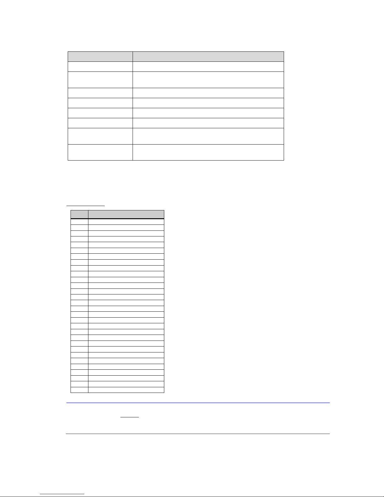
The display options of LVDS are shown in the table:
Setting
Possible Values
Flat Panel Type LVDS
Resolution 640x480, 800x600, 1024x768, 1280x1024, 1400x1050,
1600x1200, 1200x768, 1600x1050, 1920x1200
Data Bus Type 18/24 Bits, 2ppc
Refresh Rate 60 70, 72, 75, 85, 90, 100 Hz
HSYNC Polarity High, Low
VSYNC Polarity High, Low
LP Active Period Active Only à only active during SYNC
Free Running à always active
SHFCLK Active Period Active Only à only active during SYNC
Free Running à always active
To ease usage of these displays it’s possible to select the display and backlight supply voltages with the onboard
voltage selector jumpers. (Jumper LVDS and Backlight, see below)
LVDS Connector (X27)
Connector type: DF14-30P-1.25H (Hirose)
Pin
Signal
1 VDD (3.3 V, opt.5 V)
2 VDD (3.3 V, opt.5 V)
3
GND
4 GND
5
TXA3 -
6 TXA3 +
7 TXACLK 8 TXACLK +
9 GND
10 TXA2 11 TXA2 +
12 TXA1 13 TXA1 +
14 TXA0 -
15
TXA0 +
16 GND
17 TXB3 -
18 TXB3 +
19 TXBCLK -
20
TXBCLK +
21 GND
22 TXB2 23 TXB2 +
24 TXB1 25 TXB1 +
26 TXB0 27 TXB0 +
28 GND
29 LVDS DDC-CLK
30 LVDS DDC-DATA
Caution
The maximum current on all supply pins is 1A!
"A" and "B" in the signal names denote
the two possible LVDS channels.
Page 20
TME-EPIC-HURQM-R2V4.docx Revision 2.4 Page 14 of 54
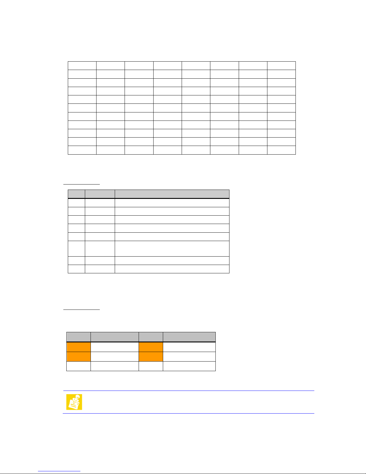
LVDS Color Mapping
Display Backlight Connector (X25)
Connector type: Hirose DF13 8 Pin
Display Voltage Selector (X11)
Jumper for voltage selection of LVDS and Backlight.
Connector type: IDC6 jumper 2.00 mm.
Use a 2mm jumper between 1-3 or 3-5 to select the display voltage.
Use a 2mm jumper between 2-4 or 4-6 to select the backlight voltage.
Pin
Signal
Pin
Signal
1
+3,3V DC
2
+12V DC
3
Display voltage
4
Backlight voltage
5
+5V DC
6
+5V DC
Default jumper setting is 3,3V for LVDS display and 12V for the inverter.
Note
An arrow on the PCB marks Pin 1
1 2 3 4 5 6 7 CLKA
1 1 0 0 0 1 1
A0
G2 R7 R6 R5 R4 R3 R2
A1
B3 B2 G7 G6 G5 G4 G3
A2
DE VS HS B7 B6 B5 B4
A3
0/B1 B1 B0 G1 G0 R1 R0
CLKB
1 1 0 0 0 1 1
B0
G2 R7 R6 R5 R4 R3 R2
B1
B3 B2 G7 G6 G5 G4 G3
B2
DE VS HS B7 B6 B5 B4
B3
0/B1 B1 B0 G1 G0 R1 R0
Pin
Direction
Signal
1 Output +12 V DC, max. 1A
2 Output +12 V DC, max. 1A
3 Output +5 V DC, max. 1A
4 Output +5 V DC, max. 1A
5 Output Signal: Backlight Brightness Control (level: 3.3 V)
6 Output Switched Inverter Power, max. 1A (refer to “
Display Voltage Selector” below)
7 GND
8 GND
Page 21

TME-EPIC-HURQM-R2V4.docx Revision 2.4 Page 15 of 54
3.4 Gigabit Ethernet Controller
There are two Ethernet ports available on two standard ETH connectors. One Ethernet by 82577 (Hanksville) with
AMT support and the other by 82574L.
Intel 82577 Gigabit Ethernet PHY
The 82577 is a single port Gigabit Ethernet Physical Layer Transceiver (PHY). It connects to the Ibex Peak-M
chipset’s integrated Media Access Controller (MAC) through a dedicated interconnect. The 82577 supports
operation at 1000/100/10 Mb/s data rates. The PHY circuitry provides a standard IEEE 802.3 Ethernet interface for
1000BASE-T, 100BASE-TX, and 10BASE-T applications (802.3, 802.3u, and 802.3ab).
The 82577 interfaces with its MAC through two interfaces: PCIe-based and SMBus. The PCIe (main) interface is
used for all link speeds when the system is in an active state (S0) while the SMBus is used only when the system
is in a low power state (Sx). In SMBus mode, the link speed is reduced to 10 Mb/s (dependent on low power
options). The PCIe interface incorporates two aspects: a PCIe SerDes (electrically) and a custom logic protocol.
Intel 82574 Gigabit Ethernet PHY
The 82574L is a single, compact, low power component that offers a fully integrated Gigabit Ethernet Media
Access Control (MAC) and Physical Layer (PHY) port. The 82574 uses the PCI Express* (PCIe*) architecture and
provides a single-port implementation in a relatively small area so it can be used for server and client
configurations as a LAN on Motherboard (LOM) design. The 82574 family can also be used in embedded
applications such as switch add-on cards and network appliances.
Ethernet Connector (X8, X29)
Connector type: Würth Midcom int. Magnetics (7499111440)
Pin
Signal
Pin
Signal
1
n.c.
2
MX1+
3
MX1-
4
MX2+
5
MX2-
6
MX3+
7
MX3-
8
MX4+
9
MX4-
10
VCT
11
Link_1000
12
Link_100
13
Link/Activity
14
+V3.3S
Page 22
TME-EPIC-HURQM-R2V4.docx Revision 2.4 Page 16 of 54
3.5 USB 2.0 Ports
The Ibex Peak contains two Enhanced Host Controller Interface (EHCI) host controllers which support up to
fourteen USB 2.0 high-speed root ports. USB 2.0 allows data transfers up to 480Mb/s. USB 2.0 based Debug Port
is also implemented in the Ibex Peak.
Thirteen USB 2.0 host ports are provided with the Hurricane-QM57. Four USB ports are available on two standard
2-port USB connectors. Another two USB ports (8/9) are available on the third standard 2-port USB connector,
but they have a maximum output current of one ampere per port.
USB 0/1 are supplied by the 5V-Standby voltage and can be used for system wakeup. Please take care of the
maximum drawn current on these ports. High currents can exceed the maximum current of the 5V-Standby
voltage of your power supply.
Four USB ports are available on two Hirose DF13 connectors. At least there are two USB ports on PCI/104Express Connector and one on PCIe Mini-Card.
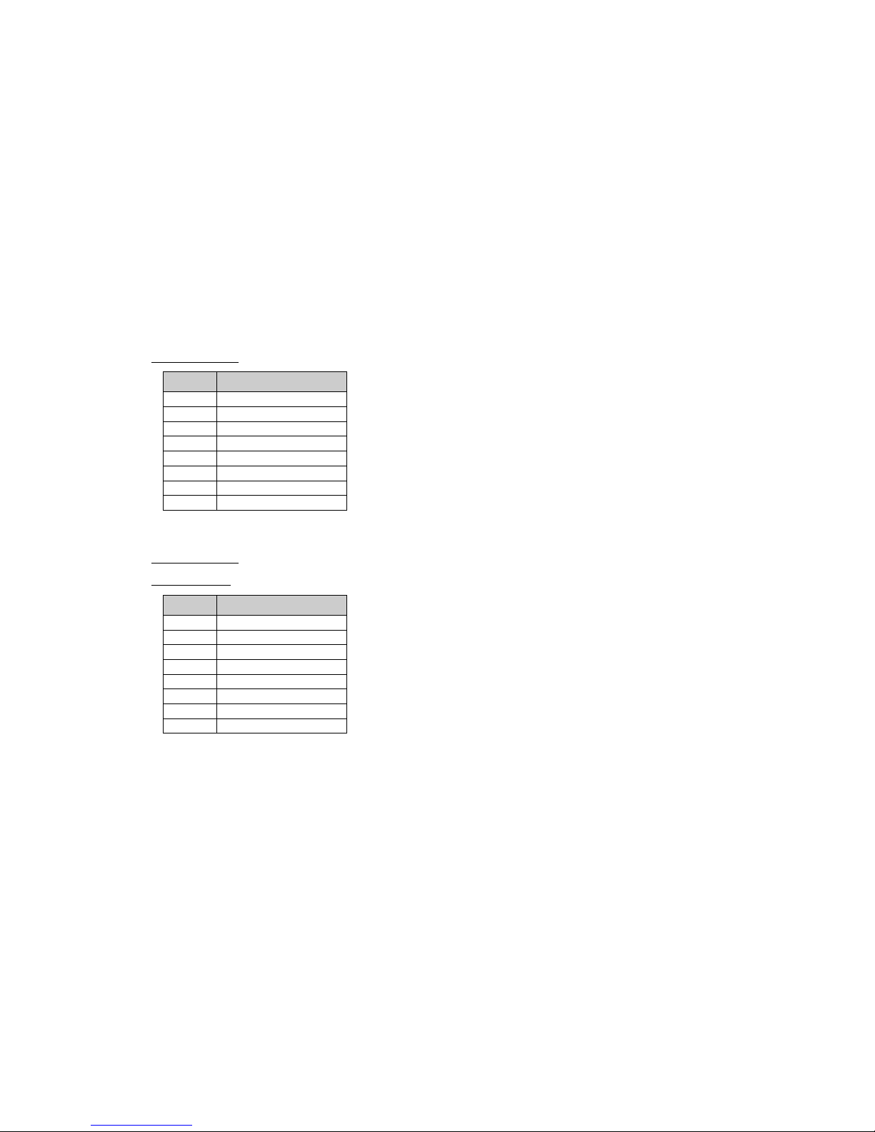
USB Connectors (0-3 & 8-9, exemplary described USB 0/1, X12, X13, X14)
Connector type: Tyco Electronics 787617
Pin
Signal
1
VCC_USB0
2 USB03 USB0+
4
USB-GND
5 USB1-
6
USB1+
7
VCC_USB1
8 USB-GND
USB Connectors (4-7, exemplary described USB 4/5, X28, X31)
Connector type: DF13 8 pin header 1.25 mm
Adapter cable: available, part.no. 862-0058-10
Pin
Signal
1 VCC_USB4
2 USB43 USB4+
4 USB-GND
5 USB-GND
6 USB57 USB5+
8 VCC_USB5
Page 23

TME-EPIC-HURQM-R2V4.docx Revision 2.4 Page 17 of 54
3.6 Serial ATA Ports
The Ibex Peak has two integrated SATA host controllers that support independent DMA operation on up to six
ports and supports data transfer rates of up to 3.0Gb/s (300 MB/s). The SATA controller contains two modes of
operation – a legacy mode using I/O space, and an AHCI mode using memory space. Software that uses legacy
mode will not have AHCI capabilities.
The Ibex Peak supports the Serial ATA Specification, Revision 1.0a. The Ibex Peak also supports several optional
sections of the Serial ATA II: Extensions to Serial ATA 1.0 Specification, Revision 1.0 (AHCI support is required for
some elements).
The Ibex Peak provides hardware support for Advanced Host Controller Interface (AHCI), a new programming
interface for SATA host controllers. Platforms supporting AHCI may take advantage of performance features such
as no master/slave designation for SATA devices—each device is treated as a master—and hardware-assisted
native command queuing. AHCI also provides usability enhancements such as Hot-Plug. AHCI requires
appropriate software support (e.g., an AHCI driver) and for some features, hardware support in the SATA device or
additional platform hardware.
There are four SATA ports available for the application on four SATA connectors.
SATA Connector (X15, X16, X17, X19)
Connector type: MOLEX 47080-4001 (horizontal)
Pin
Signal
1 GND
2 Data_TX+
3
Data_TX-
4 GND
5 Data_RX6 Data_RX+
7 GND
3.7 Audio
The Ibex Peak’s High Definition Audio (HDA) controller communicates with the external codecs over the Intel High
Definition Audio serial link. The controller consists of a set of DMA engines that are used to move samples of
digitally encoded data between system memory and an external codec(s). The Ibex Peak implements four output
DMA engines and 4 input DMA engines. The output DMA engines move digital data from system memory to a D-A
converter in a codec. Ibex Peak implements a single Serial Data Output signal (HDA_SDOUT) that is connected to
all external codecs. The input DMA engines move digital data from the A-D converter in the codec to system
memory. The Ibex Peak implements four Serial Digital Input signals (HDA_SDI[3:0]) supporting up to four codecs.
The Hurricane-QM57 uses a codec from Realtek. The ALC888 is a high-performance 7.1+2 Channel High
Definition Audio Codec.
The following I/O's are used by the Hurricane-QM57:
• Analog Input (All ADC support 44,1k/48k/96kHz sampling rate)
o Microphone left and right
o Line In left and right
• Analog output (All DAC support 44,1k/48k/96/192kHz sampling rate)
o Front left and right
o Rear left and right
o Center and Subwoofer
• Digital input (16/20/24-bit S/PDIF-in support 44,1k/48k/96/192kHz sampling rate)
o S/PDIF
• Digital output (16/20/24-bit S/PDIF-out support 44,1k/48k/96/192kHz sampling rate)
o S/PDIF
Page 24
TME-EPIC-HURQM-R2V4.docx Revision 2.4 Page 18 of 54
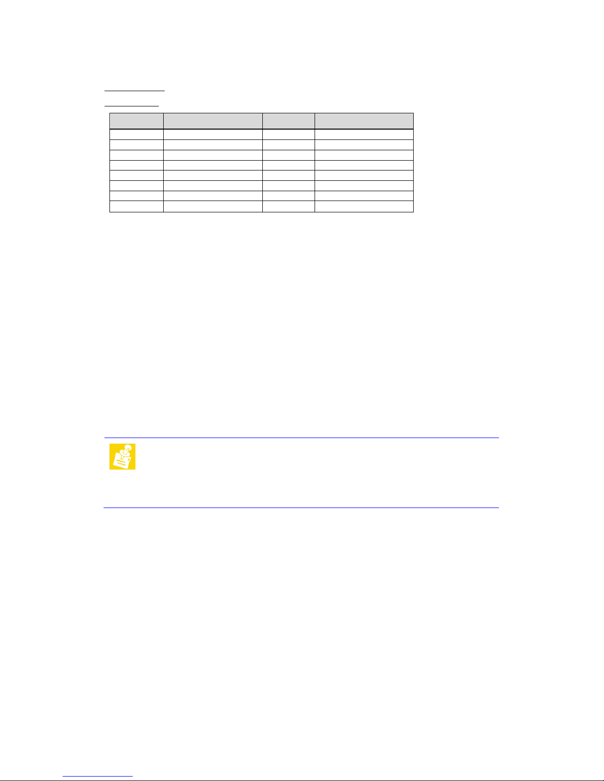
Audio Connector (X10)
Connector type: IDC16 pin header 2.00 mm
Adapter cable: available, part.no. 862-0065-10
Pin
Signal
Pin
Signal
1 Line-Out R 2 Line-Out L
3 Surrond R 4 Surrond L
5 LFE 6 Center
7 GND-Audio 8 GND-Audio
9
Line-In R
10
Line-In L
11 Mic R 12 Mic L
13 GND 14 GND
15
S/P-Dif IN
16
S/P-Dif OUT
3.8 PCI/104-Express Bus Interface
The PCI Express architecture uses familiar software and configuration interfaces of the conventional PCI bus
architecture, but provides a new high-performance physical interface while retaining software compatibility with
the existing conventional PCI infrastructure.
PCI Express is a high performance I/O architecture used in both desktop and mobile applications. This
hierarchical, point-to-point interconnect works well with on-board and slot oriented architectures. The purpose of
this Specification is to adapt PCI Express to the stacked architecture employed with 104, EPIC and EBX form
factor.
PCI/104-Express have the following features:
• Four x1 PCIe Lanes or one x4 PCIe Lane
• One x16 PCIe or optionally two x8 PCIe
• ATX power and control signals: +5V Standby, Power supply on, Power OK
• Power: +3.3V, +5V, +12V
• SMBus
Note:
The 3.3V pins on the PCI/104-Express bus are not supplied by the onboard
3.3V power supply in default. The maximum current is limited to 3.6 A. With
0R0-Resistor-Jumpers the 3.3V pins can by supplied by the onboard 3.3V
power supply, but with a lower current limit.
If a PCI/104-Express peripheral board needs 3.3V supply from the bus with
more than that limit, it must be supplied externally.
Page 25
TME-EPIC-HURQM-R2V4.docx Revision 2.4 Page 19 of 54
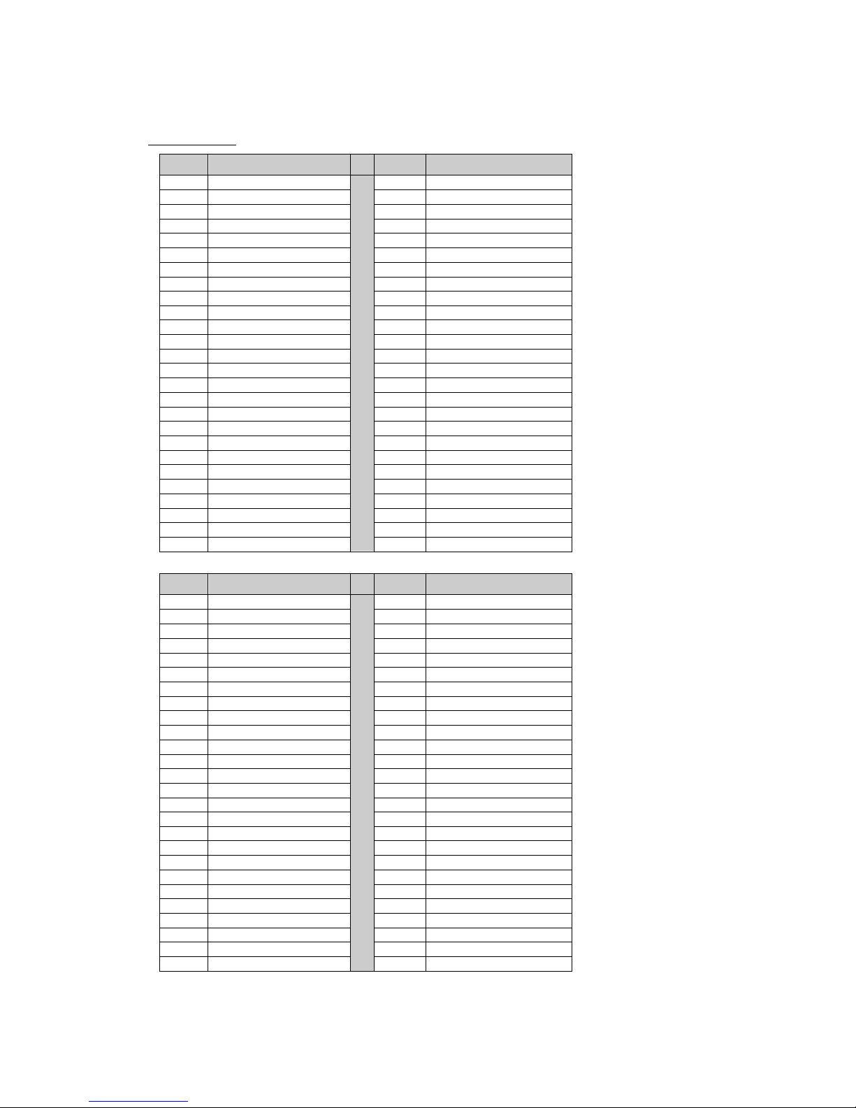
PCI/104-Express Connector (X18)
Connector Type: Samtech ASP-129637-03
Pin
Signal
Pin
Signal
1
GPIO0
+5V
2
PE_RST#
3
+3.3V
4
+3.3V
5
USB_1+
6
USB_0+
7
USB_1-
8
USB_0-
9
GND
10
GND
11
Pex1_1Tp
12
Pex1_0 Tp
13
Pex1_1Tn
14
Pex1_0 Tn
15
GND
16
GND
17
Pex1_2 Tp
18
Pex1_3 Tp
19
Pex1_2 Tn
20
Pex1_3 Tn
21
GND
22
GND
23
Pex1_1Rp
24
Pex1_0 Rp
25
Pex1_1Rn
26
Pex1_0 Rn
27
GND
28
GND
29
Pex1_2 Rp
30
Pex1_3 Rp
31
Pex1_2 Rn
32
Pex1_3 Rn
33
GND
34
GND
35
Pex1_1Clkp
36
Pex1_0Clkp
37
Pex1_1Clkn
38
Pex1_0Clkn
39
+5V_Always
40
+5V_Always
41
Pex1_2Clkp
42
Pex1_3Clkp
43
Pex1_2Clkn
44
Pex1_3Clkn
45
CPU_DIR
46
PWRGOOD
47
SMB_DAT
48
Pex16_Clkp
49
SMB_CLK
50
Pex16_Clkn
51
SMB_ALERT
52
PSON#
Pin
Signal
Pin
Signal
53
WAKE#
+5V
54
PEG_EN#
55
GND
56
GND
57
Pex16_0T(8)p
58
Pex16_0T(0)p
59
Pex16_0T(8)n
60
Pex16_0T(0)n
61
GND
62
GND
63
Pex16_0T(9)p
64
Pex16_0T(1)p
65
Pex16_0T(9)n
66
Pex16_0T(1)n
67
GND
68
GND
69
Pex16_0T(10)p
70
Pex16_0T(2)p
71
Pex16_0T(10)n
72
Pex16_0T(2)n
73
GND
74
GND
75
Pex16_0T(11)p
76
Pex16_0T(3)p
77
Pex16_0T(11)n
78
Pex16_0T(3)n
79
GND
80
GND
81
Pex16_0T(12)p
82
Pex16_0T(4)p
83
Pex16_0T(12)n
84
Pex16_0T(4)n
85
GND
86
GND
87
Pex16_0T(13)p
88
Pex16_0T(5)p
89
Pex16_0T(13)n
90
Pex16_0T(5)n
91
GND
92
GND
93
Pex16_0T(14)p
94
Pex16_0T(6)p
95
Pex16_0T(14)n
96
Pex16_0T(6)n
97
GND
98
GND
99
Pex16_0T(15)p
100
Pex16_0T(7)p
101
Pex16_0T(15)n
102
Pex16_0T(7)n
103
GND
104
GND
Page 26
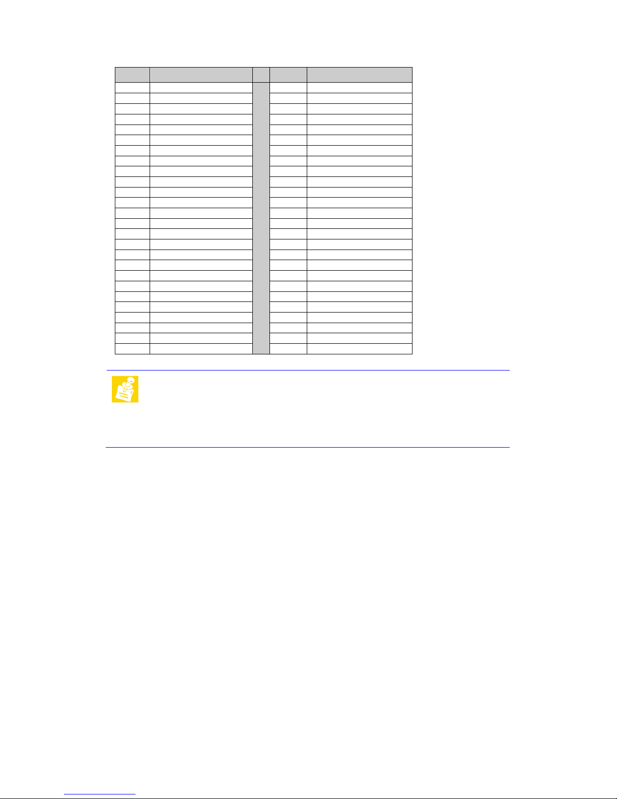
TME-EPIC-HURQM-R2V4.docx Revision 2.4 Page 20 of 54
Pin
Signal
Pin
Signal
105
SDVO_DAT
+12V
106
SDVO_CLK
107
GND
108
GND
109
Pex16_0R(8)p
110
Pex16_0R(0)p
111
Pex16_0R(8)n
112
Pex16_0R(0)n
113
GND
114
GND
115
Pex16_0R(9)p
116
Pex16_0R(1)p
117
Pex16_0R(9)n
118
Pex16_0R(1)n
119
GND
120
GND
121
Pex16_0R(10)p
122
Pex16_0R(2)p
123
Pex16_0R(10)n
124
Pex16_0R(2)n
125
GND
126
GND
127
Pex16_0R(11)p
128
Pex16_0R(3)p
129
Pex16_0R(11)n
130
Pex16_0R(3)n
131
GND
132
GND
133
Pex16_0R(12)p
134
Pex16_0R(4)p
135
Pex16_0R(12)n
136
Pex16_0R(4)n
137
GND
138
GND
139
Pex16_0R(13)p
140
Pex16_0R(5)p
141
Pex16_0R(13)n
142
Pex16_0R(5)n
143
GND
144
GND
145
Pex16_0R(14)p
146
Pex16_0R(6)p
147
Pex16_0R(14)n
148
Pex16_0R(6)n
149
GND
150
GND
151
Pex16_0R(15)p
152
Pex16_0R(7)p
153
Pex16_0R(15)n
154
Pex16_0R(7)n
155
GND
156
GND
Note:
The voltages +5V, +5VAlways and +12V are not generated by the onboard
power-supply but routed from the Power Supply Connector. The maximum
current limits are for each voltage:
+5V à 16.8A
+5VAlways à 3.6A
+12V à 8.4A
Page 27

TME-EPIC-HURQM-R2V4.docx Revision 2.4 Page 21 of 54
3.9 PC/104-Plus Bus Interface
The PC/104-Plus bus is a modification of the standard PCI bus. It allows all of the PC/104 features to be used,
together with the high speed PCI bus.
The main features are:
• PC/104-Plus Bus slot, fully compatible with PCI version 2.2 specifications.
• Integrated PCI arbitration interface (32 bit wide, 3.3V).
• Translation of PCI cycles to ISA bus.
• Translation of ISA master initiated cycle to PCI.
• Support for burst read/write from PCI master.
• 33 MHz PCI clock.
• Power: +3.3V, +5V, +12V, -12V
Note:
The 3.3V pins on the PC/104 Plus bus are not supplied by the onboard
3.3V power supply in default. The maximum current is limited to 10.0 A.
With 0R0-Resistor-Jumpers the 3.3V pins can by supplied by the onboard
3.3V power supply, but with a lower current limit.
If a PC/104-Plus peripheral board needs 3.3V supply from the bus with
more than that limit, it must be supplied externally.
Page 28
TME-EPIC-HURQM-R2V4.docx Revision 2.4 Page 22 of 54
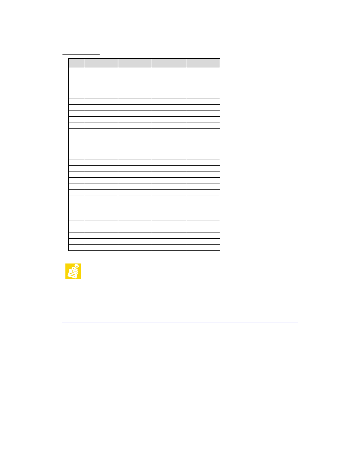
PC/104-Plus Connector (X32)
Connector Type: BSV-PC104-PLUS-EPT
Pin A B C D
1 GND Reserved +5 Volts AD00
2 VI/O AD02 AD01 +5 Volts
3 AD05 GND AD04 AD03
4 C/BE0 AD07 GND AD06
5 GND AD09 AD08 GND
6 AD11 VI/O AD10 M66EN
7 AD14 AD13 GND AD12
8 n.c. C/BE1 AD15 n.c.
9 SERR GND SB0 PAR
10 GND PERR n.c. SDONE
11 STOP n.c. LOCK GND
12 n.c. TRDY GND DEVSEL
13 FRAME GND IRDY n.c.
14 GND AD16 n.c. C/BE2
15
AD18
n.c.
AD17
GND
16 AD21 AD20 GND AD19
17 n.c. AD23 AD22 n.c.
18
IDSEL0
GND
IDSEL
IDSEL2
19 AD24 C/BE3 VI/O IDSEL3
20 GND AD26 AD25 GND
21 AD29 +5 Volts AD28 AD27
22 +5 Volts AD30 GND AD31
23 REQ0 GND REQ1 VI/O
24 GND REQ2 +5 Volts GNT0
25 GNT1 VI/O GNT2 GND
26 +5 Volts CLK0 GND CKL1
27 CLK2 +5 Volts CLK3 GND
28 GND INTD +5 Volts RST
29 +12 Volts INTA INTB INTC
30 -12 Volts REQ3 GNT3 GND
Note:
All VI/O pins are connected to 5V in default, but it’s also possible to
connect VI/O via 0R0-Resisor-Jumper to 3.3V. The voltages are supplied
by the onboard power supplies.
The voltages +5V, +12V and -12V are not generated by the onboard
power-supply but routed from the Power Supply Connector. The maximum
current limits are for each voltage:
+5V à 8A
+12V à 1A
-12V à 1A
Page 29
TME-EPIC-HURQM-R2V4.docx Revision 2.4 Page 23 of 54
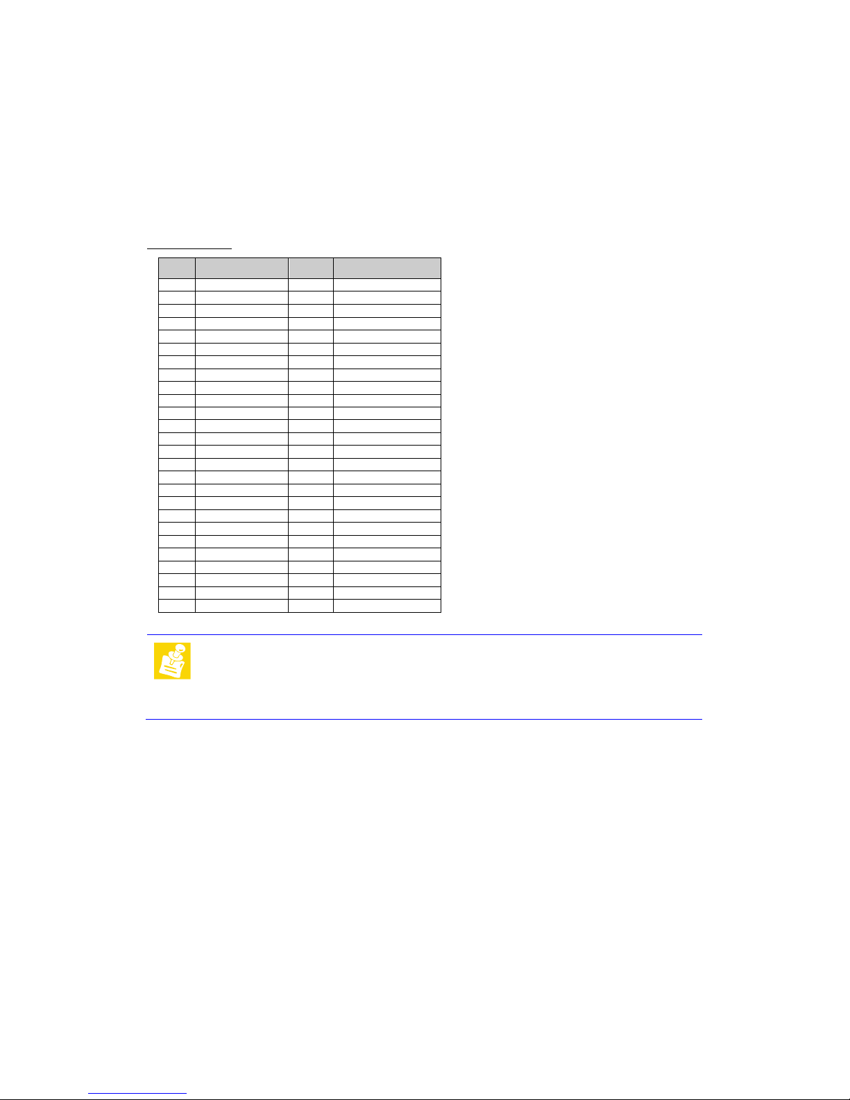
3.10 PCIe Mini-Card (X9)
The PCIe Mini Card (or Mini PCI Express) interface can be used to add IO functionality to the board. Different Mini
PCI Express boards on the market are available with functionality like WLAN or SSD (Solid State Disk)
Connector type: Molex 67910-9001
Pin
Signal
Pin
Signal
1 WAKE# 2 3V3
3 Reserved 4 GND
5 Reserved 6 1V5
7 CLKREQ# 8 UIM_PWR
9
GND
10
UIM_DATA
11 REFCLK- 12 UIM_CLK
13 REFCLK+ 14 UIM_RESET
15 GND 16 UIM_VPP
17 Reserved 18 GND
19 Reserved 20 W_DISABLE#
21
GND
22
PERST#
23 PERn0 24 3V3aux
25
PERp0
26
GND
27 GND 28 1V5
29 GND 30 SMB_CLK
31 PETn0 32 SMB_DATA
33
PETp0
34
GND
35 GND 36 USB_D37 Reserved 38 USB_D+
39 Reserved 40 GND
41 Reserved 42 LED_WWAN#
43 Reserved 44 LED_WLAN#
45
Reserved
46
LED_WPAN#
47 Reserved 48 1V5
49 Reserved 50 GND
51 Reserved 52 3V3
Note:
The pinning of the PCIe Mini Card socket is done according to the
specification of PCI SIG. The socket does
not
support Mini PCIe SSD
cards that use SATA or PATA signals like a mSATA SSD. If a Mini PCIe
SSD should be used please make sure that this one is really a PCI Express
based SSD.
Page 30
TME-EPIC-HURQM-R2V4.docx Revision 2.4 Page 24 of 54
3.11 On Board Power Supply
The ATX power supply generates all necessary voltages.
The 3.3V (also 5V, 12V, (-12V)) available on the PC104 Plus and PCI/104-Express Connectors is delivered directly
from the external power supply unit, so refer to the specification of your power supply unit for information on
maximum available power on the PCI104 Plus and PCI/104-Express connectors.
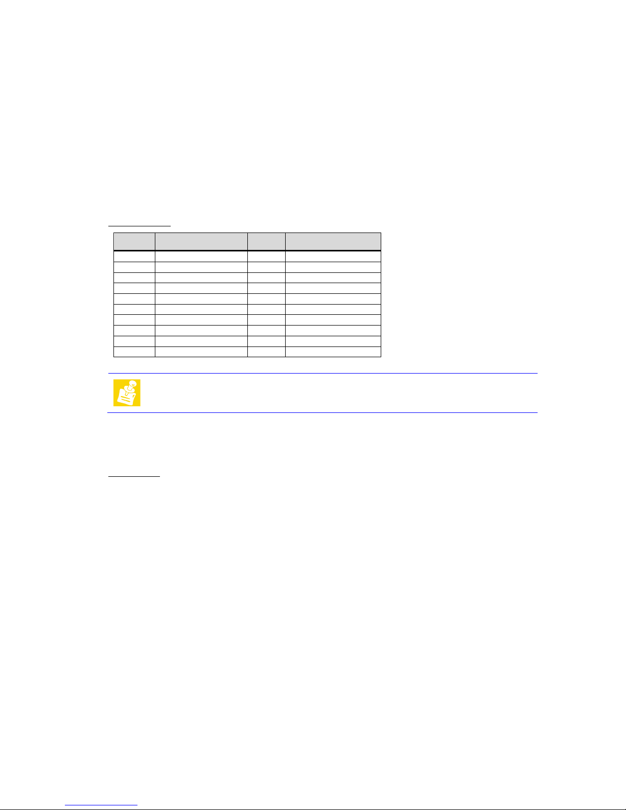
Power Connector (X26)
Connector type: ATX-Power Connector
Pin
Signal
Pin
Signal
11 +3V3 1 +3V3
12 -12V 2 +3V3
13 GND 3 GND
14 Power Supply ON 4 +5V
15 GND 5 GND
16 GND 6 +5V
17 GND 7 GND
18 -5V 8 Power OK
19 +5V 9 +5V (stand by)
20 +5V 10 +12V
Note
The board can not be supplied over PCI/104-Express or PC/104 plus bus.
Real Time Clock Backup
There is a changeable battery on board. It is required to power the real-time clock (RTC) if the power supply is
switched off.
Battery Type: BR1632, 3 Volt
Page 31
TME-EPIC-HURQM-R2V4.docx Revision 2.4 Page 25 of 54
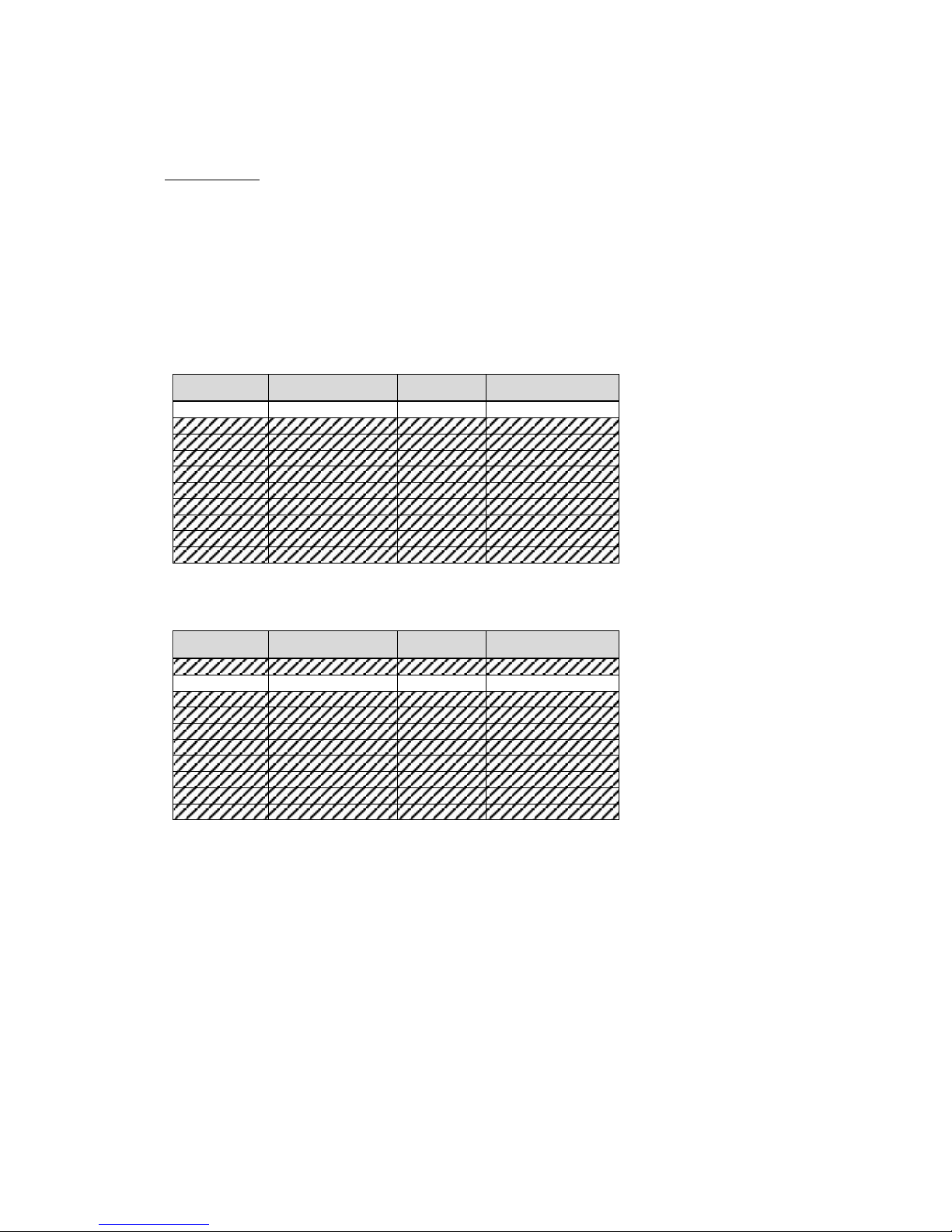
3.12 System Panel Connector (X5)
That connector is used by a different kind of signals. There is no standard cable adapter available.
Connector type: DF14 20pin header 1.25 mm
SMBus/I²C
The ICH9 contains an SMBus (System Management Bus) Host interface that allows the processor to communicate
with SMBus slaves. This interface is compatible with most I2C devices. Special I2C commands are implemented.
The ICH9’s SMBus host controller provides a mechanism for the processor to initiate communications with
SMBus peripherals (slaves). Also, the ICH9 supports slave functionality, including the Host Notify protocol. Hence,
the host controller supports eight command protocols of the SMBus interface: Quick Command, Send Byte,
Receive Byte, Write Byte/Word, Read Byte/Word, Process Call, Block Read/Write, and Host Notify.
ICH9’s SMBus also implements hardware-based Packet Error Checking for data robustness and the Address
Resolution Protocol (ARP) to dynamically provide address to all SMBus devices.
Pin
Signal
Pin
Signal
1 SMB_CLK 2 SMB_DATA
3 Power Button 4 GND
5 Reset Button 6 GND
7 HDD LED 8 +3.3V
9 Watchdog 10 +3.3V
11 Power LED 12 +3.3V
13 GPIO 14 GPIO
15 GPIO 16 GPIO
17 GPIO 18 GPIO
19 GPIO 20 GPIO
Power-Button
To power up/down the board the signal “Power-Button” must be pulled to GND.
Pin
Signal
Pin
Signal
1
SMB_CLK
2
SMB_DATA
3 Power Button 4 GND
5
Reset Button
6
GND
7 HDD LED 8 +3.3V
9 Watchdog 10 +3.3V
11
Power LED
12
+3.3V
13 GPIO 14 GPIO
15 GPIO 16 GPIO
17 GPIO 18 GPIO
19 GPIO 20 GPIO
Page 32
TME-EPIC-HURQM-R2V4.docx Revision 2.4 Page 26 of 54
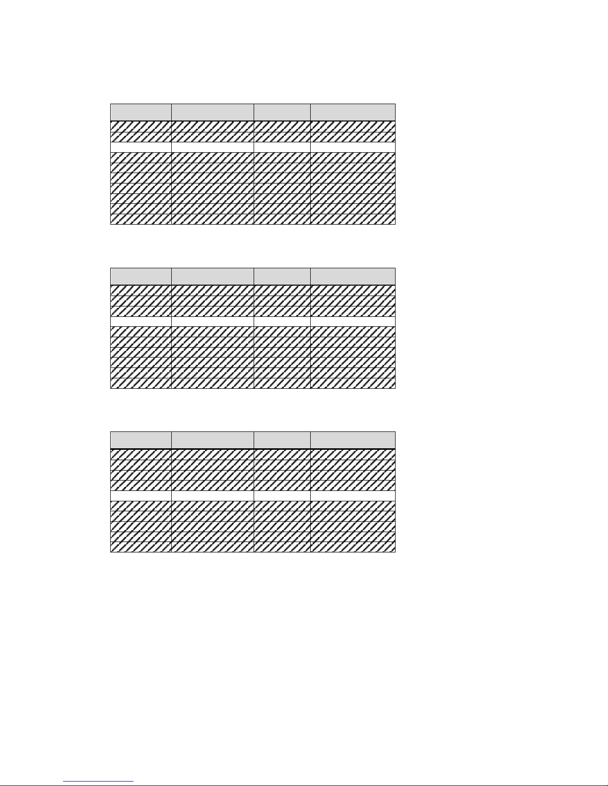
Reset-Button
To reset the board, the signal “Reset-Button” must be pulled to GND.
Pin
Signal
Pin
Signal
1 SMB_CLK 2 SMB_DATA
3 Power Button 4 GND
5 Reset Button 6 GND
7 HDD LED 8 +3.3V
9 Watchdog 10 +3.3V
11 Power LED 12 +3.3V
13 GPIO 14 GPIO
15 GPIO 16 GPIO
17 GPIO 18 GPIO
19 GPIO 20 GPIO
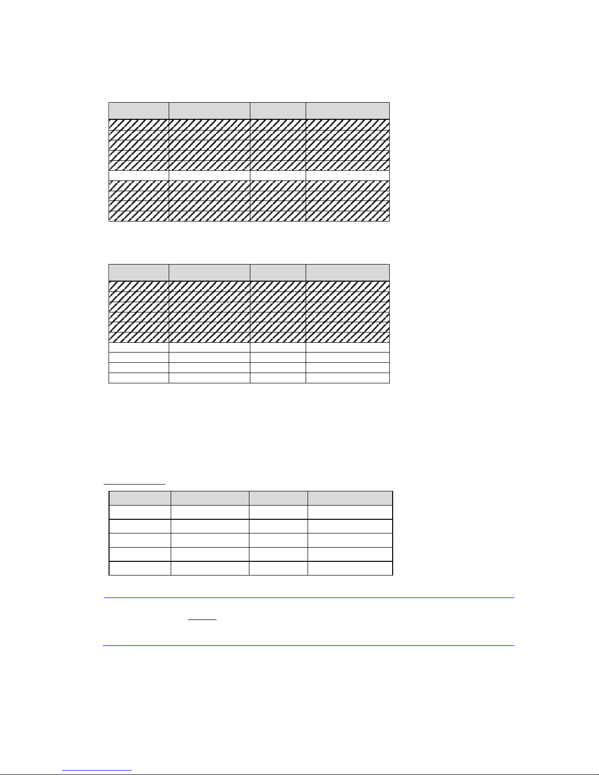
HDD-LED
To see the HDD activation, the signal "HDD LED" must be pulled to +3.3V.
Pin
Signal
Pin
Signal
1 SMB_CLK 2 SMB_DATA
3 Power Button 4 GND
5 Reset Button 6 GND
7
HDD LED
8
+3.3V
9 Watchdog 10 +3.3V
11 Power LED 12 +3.3V
13
GPIO
14
GPIO
15 GPIO 16 GPIO
17 GPIO 18 GPIO
19 GPIO 20 GPIO
Watchdog
To see the Watchdog activation, the signal "Watchdog" must be pulled to +3.3V.
Pin
Signal
Pin
Signal
1 SMB_CLK 2 SMB_DATA
3 Power Button 4 GND
5 Reset Button 6 GND
7 HDD LED 8 +3.3V
9 Watchdog 10 +3.3V
11 Power LED 12 +3.3V
13 GPIO 14 GPIO
15 GPIO 16 GPIO
17 GPIO 18 GPIO
19 GPIO 20 GPIO
Page 33
TME-EPIC-HURQM-R2V4.docx Revision 2.4 Page 27 of 54
Power-LED
To see the Power activation, the signal "Power LED" must be pulled to +3.3V.
Pin
Signal
Pin
Signal
1 SMB_CLK 2 SMB_DATA
3 Power Button 4 GND
5 Reset Button 6 GND
7 HDD LED 8 +3.3V
9 Watchdog 10 +3.3V
11 Power LED 12 +3.3V
13 GPIO 14 GPIO
15 GPIO 16 GPIO
17 GPIO 18 GPIO
19 GPIO 20 GPIO
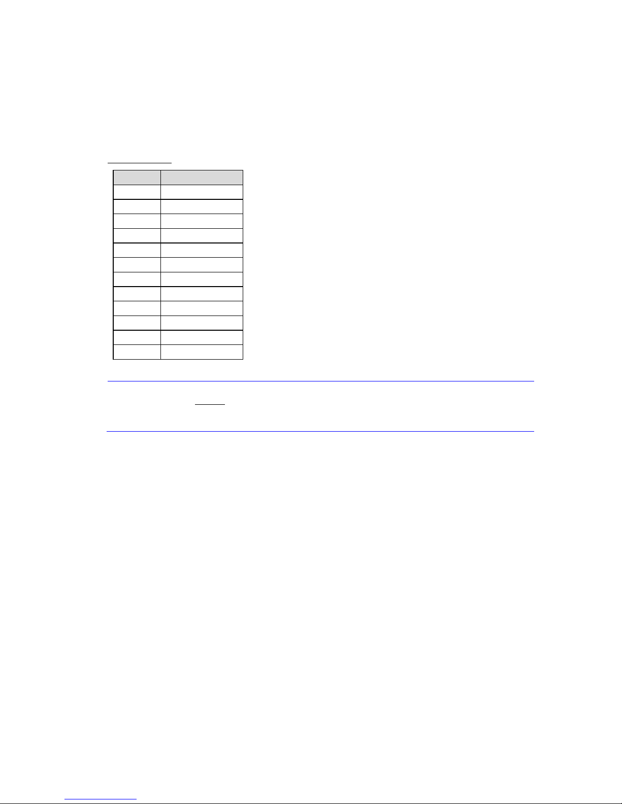
GPIO’s
Pin
Signal
Pin
Signal
1 SMB_CLK 2 SMB_DATA
3 Power Button 4 GND
5 Reset Button 6 GND
7
HDD LED
8
+3.3V
9 Watchdog 10 +3.3V
11 Power LED 12 +3.3V
13
GPIO
14
GPIO
15 GPIO 16 GPIO
17 GPIO 18 GPIO
19 GPIO 20 GPIO
3.13 Backup BIOS
In order to recover from BIOS problems, a recovery BIOS can be used. This is a special hardware unit that can be
attached to the Backup BIOS Connector.
Backup BIOS Connector (X24)
Connector Type: IDC10 pin header 2.00 mm
Caution
The maximum current on the supply pin is 0.3A!
Pin
Signal
Pin
Signal
1 SPI_HOLD#1 2 SPI_CE#1_B
3 SPI_CE#0_B 4 +3V3
5 SPI_SO 6 SPI_HOLD#0
7 n.c. 8 SPI_CLK_B
9 GND 10 SPI_SI_B
Page 34
TME-EPIC-HURQM-R2V4.docx Revision 2.4 Page 28 of 54
3.14 LPC Bus
The PCH implements a n LPC (Low Pin Count) interface, whic h is supported via this connector.
LPC Connector (X4)
Connector Type: DF13 12 pin header 1.25 mm
Caution
The maximum current on the supply pin is 0.3A!
3.15 LEMT functions
The onboard Microcontroller implements power sequencing and LEMT (LiPPERT Enhanced Management
Technology) functionality. The microcontroller communicates via the System Management Bus with the
CPU/Chipset. The following general LEMT functions are implemented:
• Total operating hours counter
Counts the number of hours the module has been run in minutes.
• On-time minutes counter
Counts the seconds since last system start.
• Temperature monitoring of CPU and Board temperature
Minimum and maximum temperature values of CPU and board are stored in flash.
• Power cycles counter
• Watchdog Timer
Set / Reset / Disable Watchdog Timer.
• System Restart Cause
Power loss / Watchdog / External Reset.
• Fail-Safe-BIOS Support
In case of a Boot failure, hardware signals tells external logic to boot from Fail-Safe-BIOS.
• Flash area
1kB Flash area for customer data
Pin
Signal
1 +3V3
2 LPC_AD0
3 LPC_AD1
4 LPC_AD2
5 LPC_AD3
6 n.c.
7 LPC_FRAME#
8 PCI_RST#
9 CLK_33_FWH
10 GND
11 INT_SERIRQ
12 LPC_DRQ#
Page 35

TME-EPIC-HURQM-R2V4.docx Revision 2.4 Page 29 of 54
• Protected Flash area
128 Bytes for Keys, ID's, etc. can stored in a write- and clear-protectable region.
• Board Identify
Vendor / Board / Serial number
Board Specific LEMT functions
Voltages
The SMC of the Hurricane-QM57 implements a Voltage Monitor and samples several Onboard-Voltages. The
Voltages can be ready by calling the LEMT function “Get Voltages”. The function returns a 16 Bit value divided in
Hi-Byte (MSB) and Lo-Byte (LSB).
ADC Channel
Voltage
Name
Voltage
Formula [V]
0 --- ---
1 --- ---
2
+V3.3A
(MSB<<8 + LSB) * 1.100 * 3.3 / 1024
3 +V0.75 (MSB<<8 + LSB) * 3.3 / 1024
4 +V1.5 (MSB<<8 + LSB) * 3.3 / 1024
5 +V1.05M (MSB<<8 + LSB) * 3.3 / 1024
6
+V1.05S_VTT
(MSB<<8 + LSB) * 3.3 / 1024
7 +V1.8S (MSB<<8 + LSB) * 3.3 / 1024
TS#-Events
TS# is activated by a Temperature sensor when a device reaches its critical temperature and released when the
device is back into its normal temperature range. This counter gives the User information of Temperature/Cooling
problems. This counter is cleared when the system is removed from power. The Hurricane-QM57 monitors the
CPU- and Board-temperature and does not support TS#-Events.
Page 36
TME-EPIC-HURQM-R2V4.docx Revision 2.4 Page 30 of 54
Exception Codes
In case of an error the SMC shows a blink code on the STATUS-LED. This error code is also reported by the SMC
Flags register. The Exception Code is not stored in the Flash Storage and is cleared when the power is removed.
Therefore the “Clear Exception Code”-Command is not supported.
Exception Code Error Message
0 NO_ERROR
2 NO_SUSCLK
3 NO_SLP_S5
4 NO_SLP_S3
5 NO_PWRGD_ATX
6 NO_PWRGD_SUS
7 NO_PWRGD_IMVP
8 NO_PWRGD_ALL_SYS
9 NO_PWRGD_MEM
12 +V3.3A
13 +V0.75
14 +V1.5
15 +V1.05M
16 +V1.05S_VTT
17 +V1.8S
18 BIOS_FAIL
19 NO_PWRGD_VGFX
20 LOW_VIN
SMC Flags
The SMC Flags return the last detected Exception Code since Power-up. The upper 3 bits of the SMC Flags
register are reserved for future use.
SMC Status
This register show of the status of SMC controlled signals on the Hurricane-QM57.
Status Bit Signal
0 SMC_WDACTIVE#
1 -
2
-
3 -
4 -
5 -
6 -
7 -
Page 37
TME-EPIC-HURQM-R2V4.docx Revision 2.4 Page 31 of 54
3.16 CPU Fan Connector (X20)
The Hurricane-QM57 provides a connector to power a CPU fan, if the module is actively cooled.
Connector Type: HIROSE-DF13-3PIN-1M25-S
Pin
Signal
1 Speed Signal from fan (yellow)
2 +12VDC, regulated (red)
3 GND (black)
3.17 Chassis Fan Supply (X21)
The Hurricane-QM57 provides a connector to power a Chassis fan.
Connector Type: HIROSE-DF13-3PIN-1M25-S
Pin
Signal
1 Speed Signal from fan (yellow)
2 +12VDC (red)
3 GND (black)
Page 38

TME-EPIC-HURQM-R2V4.docx Revision 2.4 Page 32 of 54
4 Using the Module
4.1 BIOS
The Hurricane-QM57 is delivered with a Phoenix Technology BIOS. The default settings guarantee a "ready to run"
system, even without a BIOS setup backup battery.
All setup changes of the BIOS are stored in the CMOS RAM. A copy of the CMOS RAM, excluding date and time,
is stored in the flash memory. This means that even if the backup battery runs out of power, the BIOS settings are
not lost. Only date and time will be reset to their default value.
The battery will keep that information over 2 years without any activation of the board. That depends on the use of
the board. When power is up, the battery does not lose capacity.
The BIOS revision can be easily updated on-board with software under DOS.
Configuring the Phoenix BIOS
Pressing <F2> at power-up starts the BIOS setup utility.
Initialize BIOS at first startup
It is important to initialize the BIOS setting at first startup of the board.
Call setup by pressing <F2> at power-up and executed Load Setup Defaults. Then use Exit Saving Changes or
<F10> to save and activate the new settings.
The "Setup Defaults" is the optimized BIOS setup for the Hurricane-QM57.
Booting from alternative device
Pressing the <F5> key at power-up starts the Boot Menu. Choose one of the listed bootable devices for booting.
Page 39

TME-EPIC-HURQM-R2V4.docx Revision 2.4 Page 33 of 54
EFI Shell
To start the EFI Shell you have to pressing the <F11> key at power-up.
Jumper BIOS Defaults
To reload the default values automatically at power up the jumper “BIOS Defaults” must be plugged before power
up. On power up the BIOS will recognize plugged jumper and load the setup defaults.
Page 40

TME-EPIC-HURQM-R2V4.docx Revision 2.4 Page 34 of 54
BIOS Screens
The BIOS setup utility allows setting of various board parameters. The following pictures show the different setup
menus. The Hurricane-QM57 specific settings are explained here.
Phoenix – SecureCore BIOS - Main
Phoenix – SecureCore BIOS – Main – System Information
Page 41

TME-EPIC-HURQM-R2V4.docx Revision 2.4 Page 35 of 54
Advanced
Advanced – Boot Configuration
Page 42

TME-EPIC-HURQM-R2V4.docx Revision 2.4 Page 36 of 54
Advanced – ACPI Configuration
Advanced – Processor Configuration
Page 43

TME-EPIC-HURQM-R2V4.docx Revision 2.4 Page 37 of 54
Advanced – Processor Configuration – Processor Power Management
Advanced – Peripheral Configuration
Page 44

TME-EPIC-HURQM-R2V4.docx Revision 2.4 Page 38 of 54
Advanced – HDD Configuration
Advanced – IMC Configuration
Page 45

TME-EPIC-HURQM-R2V4.docx Revision 2.4 Page 39 of 54
Advanced – IMC Configuration – NB Common Configuration
Advanced – IMC Configuration – NB Common Configuration – VT for Directed I/O
Page 46

TME-EPIC-HURQM-R2V4.docx Revision 2.4 Page 40 of 54
Advanced – IMC Configuration – NB Common Configuration – Video Configuration
Advanced – IMC Configuration – Arrandale Config
Page 47

TME-EPIC-HURQM-R2V4.docx Revision 2.4 Page 41 of 54
Advanced – IMC Configuration – Arrandale Config – P EG Con fig u ra tion
Advanced – IMC Configuration – Arrandale Config – IGD C on fig
Page 48

TME-EPIC-HURQM-R2V4.docx Revision 2.4 Page 42 of 54
Advanced – IMC Configuration – Arrandale Config – IGD Con fi g – Boot Type
Advanced – IMC Configuration – Arrandale Config – IGD Con fi g – Panel Type
Page 49

TME-EPIC-HURQM-R2V4.docx Revision 2.4 Page 43 of 54
Advanced – South Bridge Config
Advanced – South Bridge Config – SB PCI Express Config
Page 50

TME-EPIC-HURQM-R2V4.docx Revision 2.4 Page 44 of 54
Advanced – South Bridge Config – SB PCI Express Config – PCI Express Root Port1
Advanced – Network Configuration
Page 51

TME-EPIC-HURQM-R2V4.docx Revision 2.4 Page 45 of 54
Advanced – SMBIOS Event Log
Advanced – ME Configuration
Page 52

TME-EPIC-HURQM-R2V4.docx Revision 2.4 Page 46 of 54
Advanced – Thermal Configuration
Advanced – Thermal Configuration – Processor Thermal Management Submenu
Page 53

TME-EPIC-HURQM-R2V4.docx Revision 2.4 Page 47 of 54
Advanced – Thermal Configuration – Intelligent Power Sharing
Advanced – Thermal Configuration – Platform Thermal Configuration
Page 54

TME-EPIC-HURQM-R2V4.docx Revision 2.4 Page 48 of 54
Security
Boot
Page 55

TME-EPIC-HURQM-R2V4.docx Revision 2.4 Page 49 of 54
Exit
4.2 Drivers
Software drivers for Chipset, Ethernet and graphics adapter are available for the Hurricane-QM57.
These drivers can be downloaded from LiPPERT's website http://www.lippertembedded.com.
Follow the installation instructions that come with the drivers.
Page 56

TME-EPIC-HURQM-R2V4.docx Revision 2.4 Page 50 of 54
5 Address Maps
This section describes the mapping of the CPU memory and I/O address spaces.
Note:
Depending on enabled or disabled functions in the BIOS, other or more
resources may be used
5.1 Memory Address Map
Address Range (Hex) Description
000A0000-000BFFFF PCI-Bus
000A0000-000BFFFF VGASave
000D0000-000D3FFF PCI-Bus
000D4000-000D7FFF PCI-Bus
000D8000-000DBFFF PCI-Bus
3C000000-3C000FFF Resources
3C000000-FEAFFFFF PCI-Bus
D0000000-DFFFFFFF Graphics Controller
E0000000-EFFFFFFF Resources
F0000000-F03FFFFF Graphics Controller
F0400000-F041FFFF Ethernet Controller 82574L
F0400000-F04FFFFF PCI Express – 3B4A
F0420000-F0423FFF Ethernet Controller 82574L
F0700000-F071FFFF Ethernet Controller 82577LM
F0720000-F0723FFF PCI Device
F0724000-F072400F AMT
F0726000-F0726FFF PCI
F0727000-F0727FFF Ethernet Controller 82577LM
F0728000-F07283FF USB Enhanced Host Controller – 3B3C
F0729000-F07293FF USB Enhanced Host Controller – 3B34
F072A000-F072A0FF SMBus Controller – 3B30
F072B000-F072BFFF Resources
FED00000-FED003FF Timer
FED10000-FED13FFF Resources
FED18000-FED18FFF Resources
FED19000-FED19FFF Resources
FED1C000-FED1FFFF Resources
FED20000-FED3FFFF Resources
FED40000-FED44FFF Resources
Page 57

TME-EPIC-HURQM-R2V4.docx Revision 2.4 Page 51 of 54
Address Range (Hex) Description
FED45000-FED8FFFF Resources
FEE00000-FEEFFFFF Resources
FF000000-FFFFFFFF Resources
FF000000-FFFFFFFF Firmware Hub
5.2 I/O Address Map
The system chipset implements a number of registers in I/O address space. These registers occupy the following
map in the I/O space (depending on enabled or disabled functions in the BIOS other or more resources may be
used).
Address Range (Hex) Description
0000-001F DMA Controller
0000-0CF7 PCI-Bus
0020-0021 Interrupt Controller
0024-0025 Interrupt Controller
0028-0029 Interrupt Controller
002C-002D Interrupt Controller
002E-002F Resources
0030-0031 Interrupt Controller
0034-0035 Interrupt Controller
0038-0039 Interrupt Controller
003C-003D Interrupt Controller
0040-0043 Timer Controller
004E-005F Resources
0050-0053 Timer Controller
0060-0060 Resources
0061-0061 Resources
0063-0063 Resources
0064-0064 Resources
0065-0065 Resources
0067-0067 Resources
0070-0070 Resources
0070-0077 CMOS / Real Time Clock
0080-0080 Resources
0081-0091 DMA Controller
0092-0092 Resources
0093-009F DMA Controller
00A0-00A1 Interrupt Controller
00A4-00A5 Interrupt Controller
Page 58

TME-EPIC-HURQM-R2V4.docx Revision 2.4 Page 52 of 54
Address Range (Hex) Description
00A8-00A9 Interrupt Controller
00AC-00AD Interrupt Controller
00B0-00B1 Interrupt Controller
00B2-00B3 Resources
00B4-00B5 Interrupt Controller
00B8-00B9 Interrupt Controller
00BC-00BD Interrupt Controller
00C0-00DF DMA Controller
00F0-00F0 Math Coprocessor
01CE-01CF VGASave
0274-0277 ISAPnP Data port
0279-0279 ISAPnP Data port
02E8-02EF VGASave
03B0-03BB VGASave
03C0-03DF VGASave
0400-047F Resources
04D0-04D1 Interrupt Controller
0500-050F Resources
0600-0603 Resources
0680-069F Resources
0A79-0A79 ISAPnP Data port
0D00-FFFF PCI Bus
1180-11FF Resources
164E-164F Resources
1800-1807 Graphics Controller
1808-180F PCI
1810-181F SATA Controller – 3B2E
1820-183F Ethernet Controller 82577LM
1840-184F SATA Controller – 3B2E
1850-1853 SATA Controller – 3B2E
1854-1857 SATA Controller – 3B2E
1858-185F SATA Controller – 3B2E
1860-1867 SATA Controller – 3B2E
1868-186B SATA Controller – 3B2D
186C-186F SATA Controller – 3B2D
1870-187F SATA Controller – 3B2D
1880-189F SMBus Controller – 3B30
18A0-18AF SATA Controller – 3B2D
Page 59

TME-EPIC-HURQM-R2V4.docx Revision 2.4 Page 53 of 54
Address Range (Hex) Description
18B0-18B7 SATA Controller – 3B2D
18B8-18BF SATA Controller – 3B2D
2000-201F Ethernet Controller 82574L
2000-2FFF PCI Express – 3B4A
FE00-FE00 Resources
FFFF-FFFF Resources
5.3 Interrupts
IRQ (Bus) System Resource
0 (ISA) Timer
8 (ISA) Timer
9 (ISA) ACPI-conform System
13 (ISA) Math coprocessor
7 (PCI) Graphic Controller
7 (PCI) AMT
12 (PCI) AMT
16 (PCI) PCI Express – 3B42
16 (PCI) PCI Express – 3B4A
16 (PCI) USB Enhanced Host Controller – 3B3C
16 (PCI) Ethernet Controller 82574L
19 (PCI) SATA Controller – 3B2D
19 (PCI) SATA Controller – 3B2E
20 (PCI) Ethernet Controller 82577LM
23 (PCI) USB Enhanced Host Controller – 3B34
5.4 DMA Channels
DMA System Resource
4 DMA Controller
Page 60

TME-EPIC-HURQM-R2V4.docx Revision 2.4 Page 54 of 54
6 Troubleshooting
First steps if the board does not boot:
• Check the status LEDs on the board. Are all voltages properly available?
• Check the power connectors to the board, monitor and additional devices.
• Are all cables plugged on the correct connector and in the correct orientation? The board may not boot
if some of the cables are not plugged in correctly!
• Check the power supply. Is the supply voltage correct for the board? If you are not sure, read the
manual. Try plugging in a different power supply or multi-meter to check the power a wrong supply
voltage can easily FRY a computer and other electrical devices.
• Is your display ok? Is the monitor powered on? Is the monitor's video cable plugged into the video
connector? Double-check the brightness and contrast settings. Plug the monitor into another
computer if possible to verify the monitor is not the problem.
• Remove all additional devices from the system. Only the processor board, power supply, monitors and
the keyboard should remain in the system.
• Assure your cooling measures work correctly and keep the processor at a reasonable temperature.
• If all else has failed, replace the CPU Board itself.
• If system comes up then load at first the OPTIMIZED DEFAULTS in the BIOS setup and reboot.
If you need to send the board to LiPPERT for repair, be sure you get a Return Material Authorization number
(RMA) first.
Check also Appendix B (Getting Help).
Page 61

TME-EPIC-HURQM-R2V4.docx Revision 2.4 Appendix A
Contact Information
Headquarters
LiPPERT Embedded Computers GmbH
Hans-Thoma-Straße 11
68163 Mannheim
Germany
Phone +49 621 432140
Fax +49 621 4321430
E-mail [email protected]
Website www.lippertembedded.com
US Office
LiPPERT Embedded Computers, Inc.
2220 Northmont Parkway, Suite 250
Duluth, GA 30096
USA
Phone +1 (770) 295 0031
Fax +1 (678) 417 6273
E-mail [email protected]
Website www.lippertembedded.com
Page 62

TME-EPIC-HURQM-R2V4.docx Revision 2.4 Appendix B
Getting Help
Should you have technical questions that are not covered by the respective manuals, please contact our support
department at [email protected].
Please allow one working day for an answer!
Technical manuals as well as other literature for all LiPPERT products can be found in the
Products
section of
LiPPERT's website www.lippertembedded.com. Simply locate the product in question and follow the link to its
manual.
Returning Products for Repair
To return a product to LiPPERT for repair, you need to get a Return Material Authorization (RMA) number first.
Please fill in the RMA Request Form at http://www.lippertembedded.de/en/service/repairs.html and send it to us.
We'll return it to you with the RMA number.
Deliveries without a valid RMA number are returned to sender at his own cost!
LiPPERT has a written Warranty and Repair Policy, which can be retrieved from
http://www.lippertembedded.com/daten/downloads/General/BM14007_1V6.pdf
It describes how defective products are handled and what the related costs are. Please read this document
carefully before returning a product.
Page 63

TME-EPIC-HURQM-R2V4.docx Revision 2.4 Appendix C
Additional Information
Universal Serial Bus (USB) connects computers, peripherals and more at
USB
www.usb.org
PCI Express Specification, Revision 1.1 at
PCI-Express
www.pcisig.com/specifications/pciexpress/
ACPI
Advanced Configuration and Power Interface Specification (ACPI), Revision 3.0 at www.acpi.info/spec.htm
SMB
System Management Bus (SMBus) at www.smbus.org
Page 64

TME-EPIC-HURQM-R2V4.docx Revision 2.4 Appendix D
Revision History
Filename Date Edited
by
Change
TME-EPIC-HURQM-R0V0.doc 2009-11-09 UW Draft
TME-EPIC-HURQM-R0V1.doc 2010-04-23 MF Some Layout changes
Included Celeron P4505
TME-EPIC-HURQM-R0V2.doc 2010-04-27 UW Changes at chapter 5
TME-EPIC-HURQM-R0V3.doc 2010-05-17 UW Changes at chapter 4
TME-EPIC-HURQM-R0V4.doc 2010-06-24 JS Changes at chapter 3.5
TME-EPIC-HURQM-R0V5.doc 2010-07-15 UW Changed Block Diagram
TME-EPIC-HURQM-R0V6.doc 2010-09-09 PK Ch. 1.2: Correct article numbers
TME-EPIC-HURQM-R0V7.docx 2010-10-14 JS
MF
Reference Designators added to Connector Descriptions
Ch. 3.3 Text corrections
TME-EPIC-HURQM-R1V0.doc 2010-12-14 UW Changes at chapter 4
TME-EPIC-HURQM-R2V0.doc 2011-02-25 UW New Board Revision
TME-EPIC-HURQM-R2V1.doc 2011-02-25 PK Cables and cable sets amended
TME-EPIC-HURQM-R2V2.doc 2011-05-24 MF Front Picture and Picture X11 updated
TME-EPIC-HURQM-R2V3.doc 2011-06-18 MF board pictures updated to actual revision
Ch. 3.15: added board specific LEMT functions
Ch. 3.3: Correction on description for X11
TME-EPIC-HURQM-R2V4.doc 2011-07-26 MF Ch. 3.10: added note regarding use of Mini PCIe SSD in
Mini PCIe socket
 Loading...