

Lionel Trains 73-0020-250 User Manual
73-0020-250
12/06
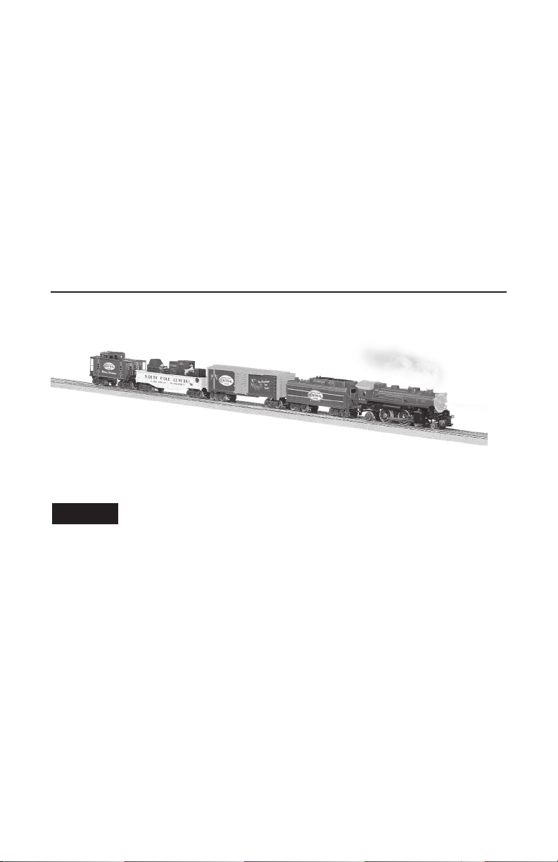
North Pole Central
Chrimas Train
Read-to-Run Set
Owner’s Manual
CAUTION—ELECTRIC TOY
NOT RECOMMENDED FOR CHILDREN UNDER EIGHT YEARS OF AGE. AS WITH
ALL ELECTRIC PRODUCTS, PRECAUTIONS SHOULD BE OBSERVED DURING
HANDLING AND USE TO REDUCE THE RISK OF ELECTRIC SHOCK.
TRANSFORMER RATINGS—INPUT: 120 VAC; 60 HZ ONLY.
AC OUTPUT: 18 V; 30 VA
Congratulations!
ongratulations on your purchase of the ready-to-run North Pole Central Christmas Train Set!
C
This set features everything you need to get started—a mighty PowerMax Transformer, a huge
loop of easy-to-assemble FasTrack track, a string of detailed cars, and a powerful Lionel locomotive.
Have fun growing with this complete train set! Start with the set components, then follow
your imagination into your own miniature world. Expand your railroad empire with additional FasTrack track sections, enhance your layout with accessories, lengthen your consist with
extra cars, or operate a new locomotive at the head end of your train! Explore the possibilities
at your authorized Lionel dealer.
Use this Owner’s Manual to learn how to set up, operate, and maintain your train set for
years of reliable operation.
North Pole Central Christmas Train Set Features
Lighted
caboose
interior
Parents!
Animated
chase
gondola
Operating
couplers
Christmas
music
boxcar
Air whistle
Forward-Neutral-Reverse
operation
Puffing
smoke
Bright
headlight
The transformer included with this set should be periodically
examined for conditions that may result in the risk of fire,
electric shock, or injury to persons (such as damage to the
output cord, blades, housing, or other parts). In the event that
such conditions exist, the transformer should not be used until
properly repaired.
The following Lionel marks may be used throughout this instruction manual and are protected under
law. All rights reserved.
Lionel®, TrainMaster®, Odyssey®, RailSounds®, CrewTalk™, TowerCom™, DynaChuff™,
StationSounds™, Pullmor®, ElectroCoupler™, Magne-Traction®, CAB-1® Remote Controller,
PowerMaster®, Lionel ZW®, ZW®, PowerHouse®, TMCC®, Lionelville™, Lockon®, Wireless
Tether™, LionMaster®, FatBoy™, American Flyer®, TrainSounds
The name FasTrack® is used with permission from Pitsco, Inc.
™
2

Table of contents
Creating your layout
Operating your PowerMax Transformer safely 4
Building your Lionel layout 5
Joining the FasTrack track sections 5
Wiring your PowerMax Transformer 6
Running your train
Running your train set 7
Adding smoke fluid to your locomotive’s smoke generator 8
Coupling 9
Operating your train 10
Operating your Christmas music boxcar 11
Experiencing the features of the PowerMax Transformer 12-13
Reverse unit procedure 14
PowerMax Transformer operation
Powering your layout with the PowerMax Transformer 15
Lubricating your locomotive 16
Replacing your locomotive’s traction tire 17
Replacing your locomotive’s headlamp 18
Lubricating the gears on your Chase Gondola 19
Replacing your Square Window Caboose lamp 20
Advanced connections: powering two isolated blocks with two transformers 21
Troubleshooting 22
Notees 23
Limited Warranty/Lionel Service 24
North Pole Central Christmas Train Set Inventory
• 4-4-2 Locomotive
• Tender with air whistle
• Christmas music boxcar
• Animated chase gondola
• Square window caboose
• PowerMax Transformer with accessory wire
• Three straight FasTrack track sections
• Eight curved FasTrack track sections
• One straight FasTrack terminal track section
• Smoke fluid
• Replacement traction tire
• Owner’s Manual
• Lionel RailRoader Club flyer
3

Creating your layout
Operating your PowerMax Transformer safely
our Lionel PowerMax Transformer is listed by Underwriter’s Laboratory Inc. and has been
Y
carefully designed to ensure peak performance. When using electrical products, basic
safety precautions should be maintained.
Be sure to observe the following guidelines:
• Read the manual thoroughly before using this device.
• This device is not recommended for children under eight years of age.
• Parents should periodically inspect this product for potential hazards and, if necessary,
have them repaired by an authorized Lionel Service Center. In the event that such a condition exists, the transformer should not be used until it has been properly repaired.
• The PowerMax Transformer is intended to be used indoors. Do not use this device if water
is present. Serious or fatal injuries may result.
• Use the PowerMax Transformer only for its intended purpose.
• The PowerMax Transformer was meant to operate on 120-volt, 60-Hertz power. Do not con-
nect this product to any other power supply.
• Do not operate the PowerMax Transformer with a damaged cord, plug, or case.
• To avoid the risk of electrical shock, do not disassemble the unit. There are no user service-
able parts inside. If damaged, take this product to an authorized Lionel Service Center.
• Do not operate the PowerMax Transformer on your layout unattended. Obstructed acces-
sories or stalled trains may overheat, resulting in damage to your layout.
• Always unplug the PowerMax Transformer from the power source when not in use.
• Never insert objects into the ventilation slots on this product. Damage to sensitive
electronic components can result.
4
Creating your layout
Building your Lionel layout
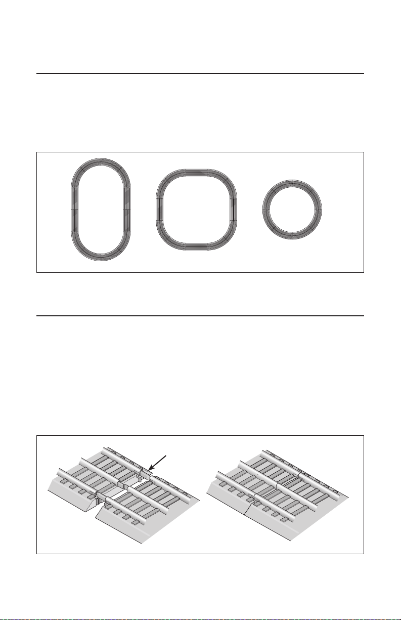
our set comes with eight curved, three straight, and one terminal section of track. Figure
Y
1 provides some examples of layouts that you can build with these track sections.
By adding more FasTrack track sections, you can create an endless number of exciting
track arrangements for more fun, action, and variety. The railroad empire of your dreams can
quickly become a reality!
Figure 1. Track layout ideas
Joining the FasTrack track sections
asTrack track sections join together easily. With interlocking roadbed sections and large
F
rail tabs, the track fits together securely so you always get good electrical contact. Take a
look at Figure 2 to see how to join the track sections.
1. Line up your two sections of track.
2. Insert the rail tabs into the openings at the ends of the corresponding
rails.
3. Press the sections together until the interlocking roadbed snaps into
place.
Figure 2. Joining the track sections
Rail tab
5
Creating your layout
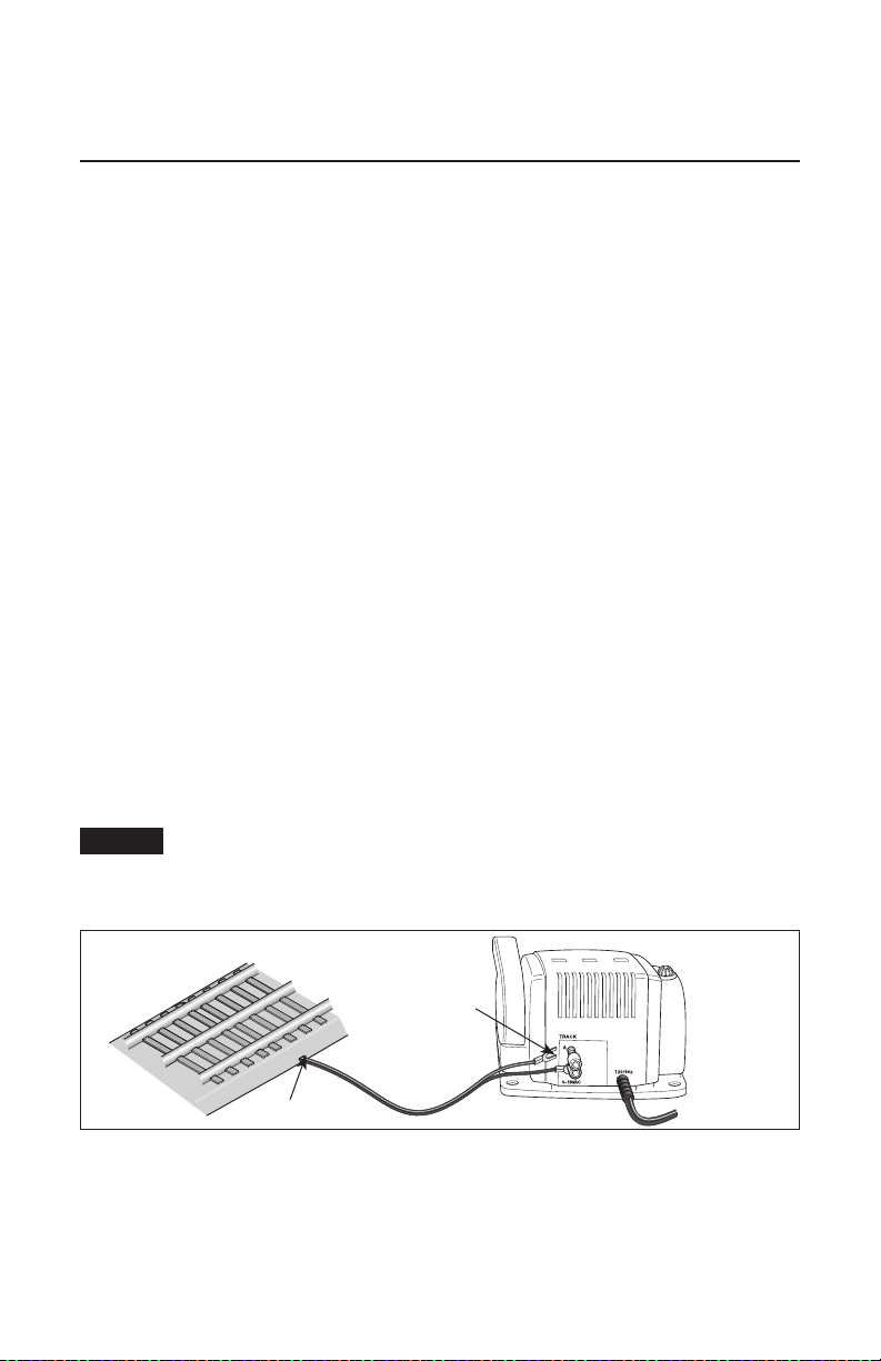
Wiring your PowerMax Transformer
onnect your FasTrack terminal section to the PowerMax Transformer. Use the wires that
C
are already attached to the terminal section. Make sure that all connections are secure.
Loose connections can produce extremely high temperatures. For this reason, do not touch
the terminals or track connections during use. Also, do not locate scenery materials such as
lichen or ground foam near the terminals.
1. Feed the wires through the notch in the FasTrack terminal section. Refer to
Figure 3.
2. Loosen the red TRACK thumbscrew terminal, then slide the spade-
shaped connector on the red wire into position. The thumbscrew post should
be positioned between the “blades” of the spade connector. Be sure that the blades are
touching the metal post. Tighten the thumbscrew to secure the connection.
3. Loosen the black TRACK thumbscrew terminal, then slide the spade-
shaped connector on the black wire into position. Tighten the thumbscrew to
secure the connection. Be sure that the blades are touching the metal post. Tighten the
thumbscrew to secure the connection.
4. Plug the PowerMax Transformer into your wall outlet (120 volts).
As your layout expands, you may also make power connections with the stripped ends
of wires, placing no more than two wires on each terminal. For best performance on
large layouts, it is recommended that you use 16-gauge wire to connect your PowerMax
Transformer to the track. On larger layouts where several track connections are required,
the use of separate junctions/terminal strips (available at your local electronics store) is
recommended to prevent voltage drops.
Caution!
FasTrack terminal section
Figure 3. Controller connections
To prevent the excessive build up of heat, be sure to select the proper wire gauge
for your layout. Track connections must be made with 18-gauge wire or heavier.
Larger layouts require a minimum of 16-gauge wire.
Notch
Spade-shaped
connector
6
Running your trains
Running your train set
With track power off, place your train set on the track.
Refer to page 8 for information on coupling the cars.
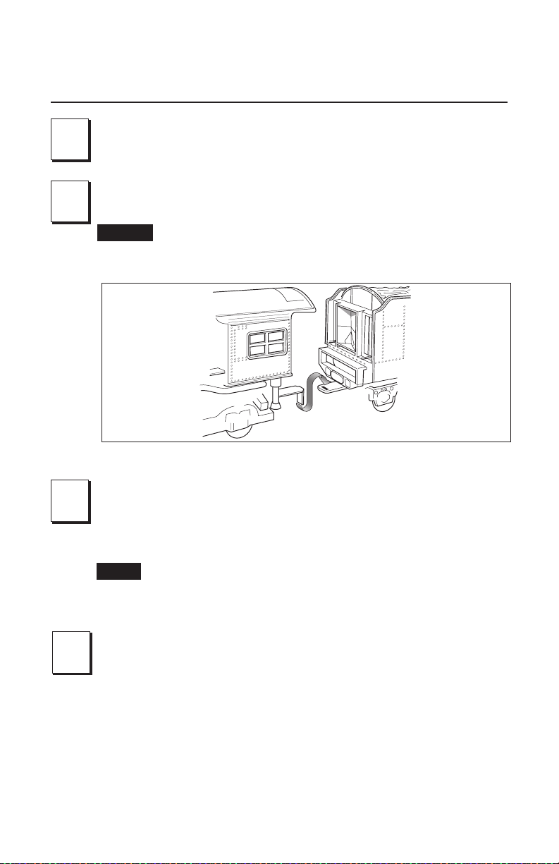
1
Connect the drawbar between the locomotive and tender.
See Figure 4.
2
Caution!
Figure 4. Drawbar connection
If the smoke unit switch is in the ON position, add smoke fluid to your
locomotive’s stack to prevent damage to the smoke unit. Refer to
page 8 for additional information.
Power up your locomotive with your transformer.
3
3
Your locomotive is designed to operate on 7-15 volts alternating current. Virtually all Lionel and Lionel-compatible alternating-current transformers
are suitable.
Note!
Move ‘em out!
4
Get your locomotive moving. Your locomotive goes through a repeating pattern
of operations: forward, neutral, reverse, neutral, and so on. To sequence the reverse
unit, press the DIRECTION button on your transformer, or briefly bring the throttle
all the way back to the OFF position and then forward. Each press of the DIRECTION
button or interruption in track power causes the locomotive to advance to the next
operational state.
Adjust track voltage until your locomotive moves at your desired speed.
Do not power your locomotive with direct-current (DC) transformers.
The locomotive was designed for use with alternating-current (AC)
transformers only.
7
Running your train
Adding smoke fluid to your locomotive’s smoke generator
our locomotive is equipped with a smoke generator that produces safe, clean white smoke
Y
during operation if the smoke unit switch is in the ON position. Refer to Figure 8 on
page 14 for the location of the switch.
The smoke generator requires the periodic addition of Lionel smoke fluid in order to function.
A small bottle of smoke fluid is included with this set. Press down and unscrew the cap. Pierce
the end of the nozzle with a pin, then add about four drops of fluid directly into the locomotive’s
stack. Smoke production commences momentarily. It will start faster if you run your locomotive
at higher speeds. When smoke production decreases, add more fluid (about four drops). An idle
locomotive will not smoke.
Smoke production is greater at higher voltages and when the locomotive is pulling a heavy
load or a long consist.
If you prefer to operate the locomotive without smoke or you do not want to add
Note!
smoke fluid, slide the smoke unit switch to the OFF position.
Caution!
When the smoke unit switch is in the ON position, always keep a small amount
of smoke fluid in the locomotive’s smoke generator; the generator’s element
can become damaged if operated without smoke fluid. This is particularly true
if your locomotive sits in neutral for an extended period of time without smoke
fluid in the generator.
8
 Loading...