

Lionel ZW-L Transformer Owner's Manual
73-7921-250
2/14
ZW-L Transformer
Owner’s Manual
ZW-L Transformer
Owner’s Manual
ELECTRICALLY-OPERATED PRODUCT:
NOT RECOMMENDED FOR CHILDREN UNDER FOURTEEN YEARS OF AGE. AS
WITH ALL ELECTRIC PRODUCTS, PRECAUTIONS SHOULD BE OBSERVED DURING HANDLING AND USE TO PREVENT ELECTRIC SHOCK. TRANSFORMER
RATINGS—INPUT: 120 VAC; 50/60 HZ. AC OUTPUT: 18 V; 620 VA.
CAUTION—

Congratulations!
2
C
ongratulations on your purchase of the Lionel ZW-L Transformer! True to the signature design
elements of its iconic predecessor, the ZW-L Transformer features four-handle operation so you
can run up to four different trains or accessories at the same time.
In the Conventional environment, the two engineer-type handles provide independent control of
two variable voltage circuits with whistle/horn, bell, and direction control for train operation. The
center controls can be set to your desired voltage for operating accessories.
In the Command Control environment, you can use the ZW-L Transformer to run your
Conventional locomotives by remote control. Your CAB-2/CAB-1 Remote Controller can control the
four individual outputs, each using a unique train (TR) or engine (ENG) ID#. Whistle/horn, bell,
and direction commands are available for each output. Plus, you can throw the ElectroCouplers on
select Conventional locomotives.
Read this manual thoroughly before using the system. It has important information on the
setup and operation of your transformer. If you have any questions, contact your Factory Trained
Authorized Lionel Service Station or call Lionel Service at 586-949-4100.
The following Lionel marks are used throughout this Owner’s Manual and are protected under
law. All rights reserved.
Lionel
®
, LEGACY™, FasTrack®, TrainMaster®, Odyssey®, RailSounds®, CrewTalk™, TowerCom™,
DynaChuff
™
, StationSounds™, Pullmor®, ElectroCoupler™, Magne-Traction®, CAB-1® Remote
Controller, American Flyer
®
, Lionel ZW®, ZW®, MagniVision®, TMCC®, Lionelville®, Wireless
Tether
™
, Powerhouse™, LionMaster®, Conventional Classics™, Postwar Celebration Series™,
TruRail
™
, PH-1 Powerhouse®, Powermaster®, Powerstation-Powerhouse®, Accessory Motor
Controller
™
, AMC™, Accessory Switch Controller™, ASC™, Action Recorder Controller™, ARC™, Track
Power Controller 300
™
, TPC 300™, Track Power Controller 400™, TPC 400™, Block Power
Controller
™
, BPC™, Operating Track Controller™, OTC™, FatBoy™, Lionel Lines®, Joshua Lionel
Cowen Series
™
, Lockon®, TrainSounds™, MultiHorn™, MultiWhistle™, Choo-Choo™, SensorTrack
™

3
Table of contents
Safety information
Operating your ZW-L Transformer safely 4
Protecting your layout from overloads 5
Features overview
Operating controls 6-7
Transformer controls 8-9
ZW-L Transformer set-up
Connecting the ZW-L Transformer to your track 10-11
Supplying power across a large layout 12
Connecting the ZW-L Transformer to your accessories 13
Conventional operation
Operating your trains and accessories in the Conventional environment 14
Operating your layout with a single throttle lever (Throttle A) 15
Command Control operation
Operating Conventional locomotives in the Command Control environment
using a CAB-2/CAB-1 Remote Controller 16
Connecting the Command Base to the ZW-L Transformer 17
Operating your layout in the Command Control environment using a single output 18
LEGACY Control System operations
LEGACY Control System operations 19
Assigning a unique ENG or TR ID# to each ZW-L output 19
Setting the device type and control mode for each ZW-L output 20
LEGACY CAB-2 Remote Controller commands 21
TrainMaster Command Control operations
TrainMaster Command Control operations 22
CAB-1 Remote Controller commands 23
Non-Lionel locomotive operation
Running non-Lionel locomotives using your CAB-2/CAB-1 Remote Controller 24
Maintenance and service
Troubleshooting 25-26
FCC Statement 27
Lionel Limited Warranty Policy & Service 28

Operating your ZW-L Transformer safely
4
Safety Information
Y
our Lionel ZW-L Transformer is ETL-listed and has been carefully designed to ensure peak
performance. When using electrical devices, basic safety precautions should be observed.
IMPORTANT SAFETY INSTRUCTIONS: READ CAREFULLY AND KEEP FOR FUTURE
REFERENCE.
• Read the manual and cautionary markings on the ZW-L Transformer thoroughly before using
this device.
• This device is not recommended for children under fourteen years of age.
• Always unplug the ZW-L Transformer from the power source when not in use. Do not unplug by
pulling the cord.
• Never insert objects into the ventilation slots on this device. Damage to sensitive electronic com-
ponents can result.
WARNING:
• The ZW-L Transformer was meant to operate on 120-volt, 50/60-Hertz power. Do not connect this
device to any other power supply.
• Parents should periodically inspect this device for potential hazards and, if necessary, have them
repaired by an authorized Lionel Service Center. In the event that such a condition exists, the
transformer should not be used until it has been properly repaired.
• The ZW-L Transformer is intended to be used indoors. Do not use this device outdoors or if water
is present. Serious or fatal injuries may result.
• Use the ZW-L Transformer only for its intended purpose.
• Do not operate the ZW-L Transformer with a damaged cord, plug, or case.
• To avoid the risk of electrical shock, do not disassemble the unit. There are no user service-
able parts inside. If damaged, take this device to a Factory Trained Lionel Service Station. Visit
www.lionel.com for a list of Lionel Service Stations.
• Do not operate the ZW-L Transformer on your layout unattended. Obstructed accessories or
stalled trains may overheat, resulting in damage to your layout.
• Periodically inspect all output connections to make sure that they are secure. A loose connection
can produce extremely high temperatures.
5
Safety Information
Y
our Lionel ZW-L is equipped with three levels of overload protection: dynamic power limiting,
fold-back current limit, and circuit breakers. Each output has its own fold-back current limit and
circuit breaker. The dynamic power limiting is applied across all four outputs. This provides multi-layer
protection for your trains and transformer while supplying the maximum power possible for pulling
lighted cars or fighting over grades with heavy loads.
Dynamic power limiting allows the 620W available from the transformer to be shared across the four
outputs as necessary to power the connected loads. Up to 180W is available to each output as long as
the total power of all four outputs does not exceed the 620W transformer rating. When the 620W total is
reached the output that tried to take more power will be limited to maintain the 620W total. The red light
on the transformer will flash while the output is being limited. The transformer can run in this mode
indefinitely and will not shut down. When more power becomes available because of a change in the
demand from the other outputs it will be automatically given to the limited output.
The fold-back current limit protects your transformer and layout from damage caused by severe overloads and short circuits in the case of derailments or objects falling on the track. At the same time it prevents the inconvenience of nuisance tripping caused by momentary overloads. It continuously monitors
the output current of all four outputs. When there is a short on any of the outputs it will reduce the voltage
on that output in a fraction of a second to hold the current at 10A. If the short circuit is not corrected in
3 seconds the transformer will interrupt power to that output. All other outputs will be unaffected. During
the 3 seconds the red light on the ZW-L will flash. Once the output is shut down the red light will come on
solid. To indicate which output(s) are experiencing the problem, the back light of the meter assigned to
that output will be turned off. Refer to Figure 1 for the meters assigned to each output. For Conventional
operation, move the throttle for that output to the Off position to reset the Transformer and resume normal
operation. For Command operation press RESET or enter AUX1, 0 on the CAB-2/CAB-1 for that output.
The circuit breakers on the ZW-L Transformer are designed as a fail-safe for the electronic over-current
protection. Because most problems will be protected by and corrected during fold-back mode operation
(described in the previous section), circuit breakers should be tripped infrequently.
In the event that a breaker is tripped, the backlight on the meter assigned to that output will be turned
off. Refer to Figure 1 for the meters assigned to each output. Correct the short circuit (e.g., make sure that
the train's wheels are properly on the track and remove any foreign objects from the rails), return the
handle(s) to the Off position, and then press the circuit breaker buttons shown in Figure 3 on page 9 to
reset power.
Protecting your layout from overloads
Output A-U
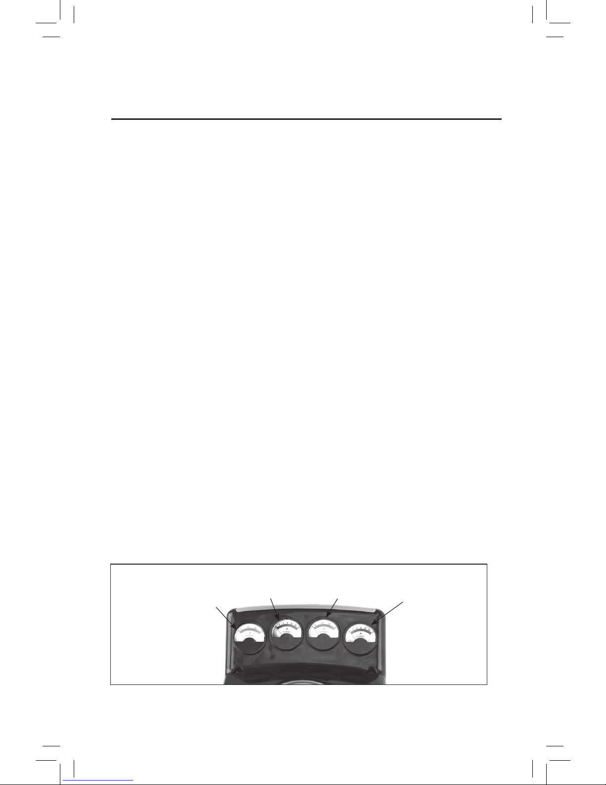
Figure 1. Meter light assignments (to show active fold-back mode/over-current protection)
Output B-UOutput C-U
Output D-U
To indicate the output(s)
experiencing a problem, the
back-light on the meter for
that output will turn off.
If a backlight is off, check for a short circuit or derailment on the corresponding output.

T
he ZW-L Transformer's main operating controls are highlighted in this section. Refer to Figure 2
on page 7 for the location of these features.
THROTTLE LEVERS (all outputs)
Each throttle lever controls the voltage to each of the corresponding outputs. Push the levers forward to increase track power. Throttles A and D have corresponding horn/whistle, bell, and direction
buttons, making them ideal for full locomotive operation. Throttles B and C have variable voltage,
making them ideal for accessory operation.
In single-lever mode, Throttle A controls the voltage to all four outputs. Throttles B, C, and D set
the maximum voltage available from the corresponding outputs.
DIRECTION (Outputs A-U and D-U)
For Outputs A-U and D-U in regular 4-channel mode, the DIRECTION control buttons interrupts
track power to activate the reverse unit in your locomotives. Your locomotive will not respond to this
button when the reverse unit switch is in the OFF position.
WHISTLE/HORN (Outputs A and D)
For Outputs A-U and D-U in regular 4-channel mode, the WHISTLE/HORN button will activate
your locomotive’s whistle or horn. The sound will continue until the button is released. No external
sound activation buttons are needed.
BELL (Outputs A and D)
For Outputs A-U and D-U in regular 4-channel mode, the BELL button will activate the bell sounds
on locomotives equipped with this feature. Press the BELL button to begin the sounds; press the button
again to turn off the ringing.
Do not activate horns, whistles, or bells on RailSounds-equipped locomotives until track
power has been turned on for a few moments, or a continuous horn/whistle or bell sound
may occur. To correct this problem, simply turn off the transformer, then turn it back on.
POWER SWITCH
Use the power switch to turn on power to your transformer. The transformer should be switched Off
and unplugged when not in use.
GREEN INDICATOR LIGHT
The green power indicator light will remain on during normal operation.
RED INDICATOR LIGHT
The red light will begin to flash if you exceed the power limit of the Transformer. The red light will
remain on if an output has shut down because of an overload.
"LIONEL" LIGHT
The "LIONEL" light on the front of the unit will remain on during normal operation. For
Command operation, the light will flash to indicate setting the ID# and flicker to indicate a weak or
absent Command signal.
6
Features overview
Operating controls
Note!
7
Features overview
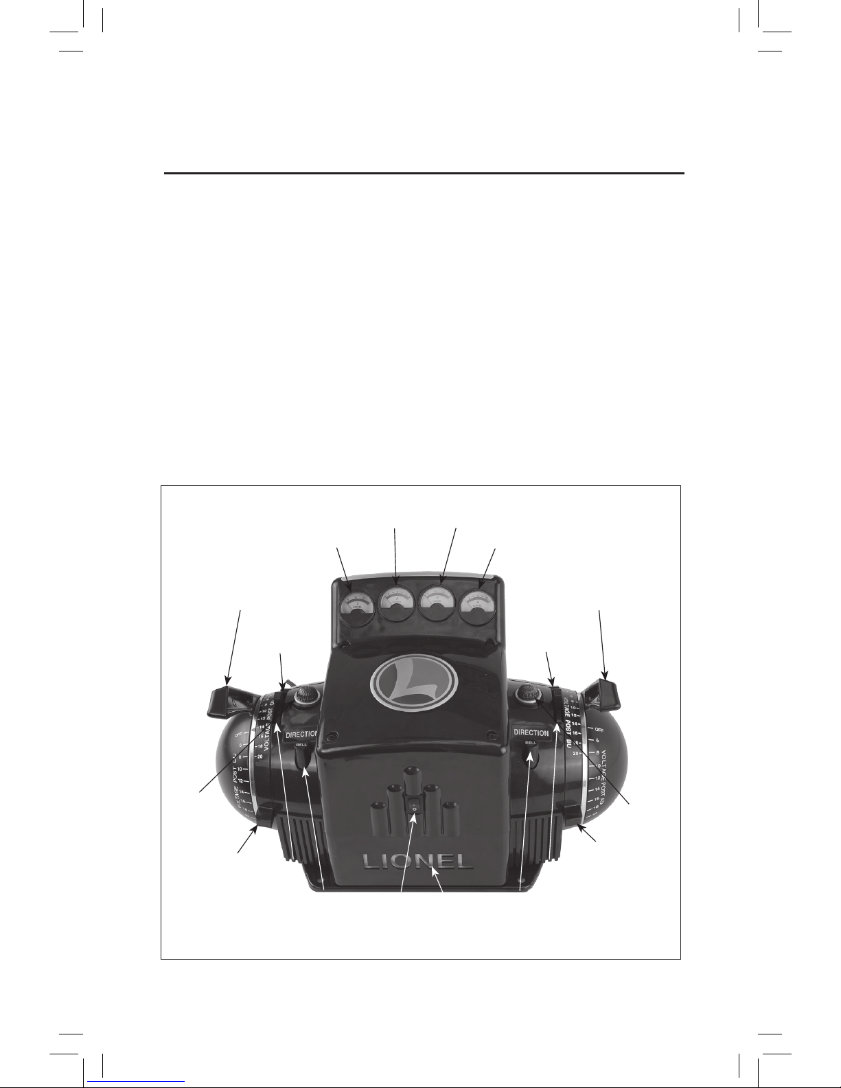
Power
switch
Volt meter (Outputs A-B)
Direction
(Output A)
Throttle Lever A
Throttle Lever D
Figure 2. Operating controls
Amp meter (Outputs A-B)
Amp meter (Outputs C-D)
Volt meter (Outputs C-D)
Throttle C
Throttle B
Whistle
(Output A)
Bell
(Output A)
Direction
(Output D)
Whistle
(Output D)
Bell
(Output D)
METERS
The ZW-L Transformer features two voltage meters. See Figure 2. The right-hand meter reads the
voltage on Outputs A-U and B-U (default reading is Output A-U); the left-hand meter reads the voltage on Outputs C-U and D-U (default reading is Output D-U).
To read the voltage on Output B-U or C-U, touch the corresponding lever with your fingers or
address these outputs with your CAB Remote Controller and adjust the voltage. The back-lighting will
be brighter as the meter displays the voltage on the B-U and C-U outputs, as long as your fingers are
in contact with the levers or the voltage is adjusted using the Remote Controller.
Likewise, the ZW-L Transformer features two amperage meters. The right-hand meter reads the
amperage on Outputs A-U and B-U (default reading is Output A-U); the left-hand meter reads the
amperage on Outputs C-U and D-U (default reading is Output D-U).
To read the amperage on Output B-U or C-U, touch the corresponding lever with your fingers or
address these outputs with your CAB Remote Controller and adjust the voltage. The back-lighting will
be brighter as the meter displays the amperage on Outputs B-U and C-U, as long as your fingers are in
contact with the levers or the voltage is adjusted using the Remote Controller.
Operating controls (continued)
Green light
Red light
LIONEL
light

8
Transformer controls
T
he transformer controls and binding posts located on the back of the transformer are highlighted
in this section. Refer to Figure 3 on page 9 for the location of these features.
BREAKERS (for outputs A-D)
Four circuit breakers are provided, one for each output. For more information, please see page 5.
COMMAND/CONVENTIONAL (CMD/CONV) SWITCH
For Conventional operation, set the COMMAND/CONVENTIONAL switch to CONV. To operate the
ZW-L Transformer with a CAB-2 or CAB-1 Remote Controller, set the switch to CMD.
RUN/PROGRAM (RUN/PGM) SWITCH
For operation in the Command environment, slide the switch to the PGM position to assign a
unique TR or ENG ID# to each output; otherwise, leave the switch in the RUN position. For more
information, see pages 19 and 21.
1 CHANNEL/4 CHANNEL (1-CH/4-CH) SWITCH
To control each output with the four corresponding throttle levers, slide the switch to the 4-CH
position. To control the four outputs using a single lever (Throttle A), slide the switch to the 1-CH
position. For more information, see pages 15 and 23.
Direction, whistle and bell commands are sent on all four outputs in 1-channel
(single-handle) operation mode.
BINDING POSTS (for outputs A-D)
For track and accessory connections.
COMMAND BASE BINDING POST
For Command Control operation. For added convenience, connect the communication wire from
the Command Base to this post as an alternative to the outside rail. See page 17 for more information
INTERNAL COOLING FAN
Temperature controlled. The fan will cycle on and off as needed.
Features overview
Note!
Features overview
9
Transformer controls (continued)
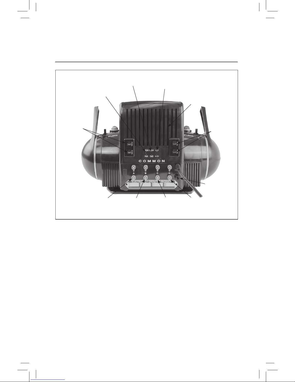
Circuit
breakers
Figure 3. Transformer controls and features
A-U Binding
posts (Output A)
Command/
Conventional switch
Command Base
binding post
B-U Binding
posts (Output B)
C-U Binding
posts (Output C)
D-U Binding
posts (Output D)
Run/Program
switch
1 Channel/4 Channel
switch
Internal cooling fan
Circuit
breakers
 Loading...