

Lionel Century Club II, Union Pacific M-10000, Century Club II Union Pacific M-10000, 75-1007-250 Owner's Manual
Century Club II
Union Pacific M-10000
Owner’s Manual
75-1007-250
8/02
®
SYSTEM
featuring
and

Table of contents
Transformer operations
Running your M-10000 with a Lionel transformer 3
Locking your locomotive into a single operational state 4
Coupling your M-10000 5
Installing a Lionel Sound Activation Button 6
RailSounds operations
Your locomotive’s RailSounds system—the basics 7
Experiencing the range of your locomotive’s RailSounds system 8
Notes on RailSounds 8
Odyssey System operations
The Odyssey System 9
Odyssey System conventional (transformer) operation 9
Odyssey System Command operation 9
TrainMaster Command operations
The Command Control environment 10
Running your locomotive in the TrainMaster Command environment 11
CAB-1 commands for your locomotive 11
CAB-1 numeric keypad commands for your locomotive 12
Tuning your locomotive’s performance 13
Assigning your locomotive a new ID# 14
Reprogramming the Command reverse unit to restore features 15
Maintaining and servicing your locomotive
Adding fluid to your locomotive’s smoke generator 16
Lubricating your locomotive and passenger cars 17
Servicing the lamps on your M-10000 18
Replacing the traction tires 19
Caring for the locomotive’s antenna 19
Limited Warranty/Lionel Service 20
C
ongratulations on your purchase of the Lionel Century Club II M-10000! The famous
M-10000 locomotive is equipped with TrainMaster Command Control and the Odyssey System
for speed control. Riding on shared trucks, two articulated passenger cars follow the locomotive.
Congratulations!
Features of the M-10000
• TrainMaster Command Control
equipped
• RailSounds sound system with
CrewTalk communication and
TowerCom announcements
(in Command)
• Odyssey System for speed control
• T wo maintenance-fr ee,powerful motors
with flywheels
• Fan-driven smoke unit
• Operating headlight and rear marker
lights
• Interior lighting
• Tire-Traction
• Gold-plated details
• Gold Century Club II markings
The following Lionel marks may be used throughout this instruction manual and are protected under
law. All rights reserved.
Lionel®, TrainMaster®, Odyssey®, RailSounds™, CrewTalk™, TowerCom™, DynaChuff™,
StationSounds™, Pullmor®, ElectroCoupler™, Magne-Traction®, CAB-1 Remote Controller®,
PowerMaster®, Lionel ZW®, ZW®, PowerHouse®, TMCC™, Lionelville™
3
3
3
Move ‘em out!
Get your M-10000 moving. Press the DIRECTIONbutton on your CAB-1
Remote Controller or Lionel transformer. This sequences the Command reverse unit
to the next operating state.
Adjust track voltage until your locomotive moves at your desired speed. To
increase speed, increase track voltage. To decrease speed, reduce voltage. To stop the
locomotive, turn-off track power.
Place your locomotive on Lionel or Lionel-compatible
O gauge track.
2
2
Power up your locomotive with your transformer.
Your locomotive is designed to operate on 8-18 volts alternating
current. Virtually all Lionel and Lionel-compatible alternating-current
transformers are suitable.
Do not power your locomotive with direct current (DC). Damage to
sensitive electronic components may occur.
When you first power up your track, the locomotive will wait
between three and eight seconds as it “listens” for digital language from the
TrainMaster Command Base (available separately). When it has determined that it’s
on a conventional (non-Command) railroad, the locomotive’s headlight will
illuminate and RailSounds will fire up. At this point, the locomotive is in neutral.
(This occurs when placing the locomotive on your railroad for the first time.
Thereafter, it will start in forward following every three-second power
interruption.)
1
1
Running your M-10000 with a Lionel transformer
Transformer operations
Caution!
Caution!
Note!
Curves must have a minimum diameter of 72”.
To couple the articulated M-10000 consist, connect a vestibule to one of
the cars at each articulation by pressing the vestibule assembly onto the end of one
car. The clasp slides over and catches the brass ring, and the contacts lock around
the post. Next, arrange the cars on the track and, holding them horizontally, slide
the vestibules into the ends of the cars. Once again, the clasp will catch the brass
ring and the contacts will lock around the post. Refer to Figure 2 on page 5.
Be sure that track power is off before coupling the cars to prevent accidental short
circuits.
Note!
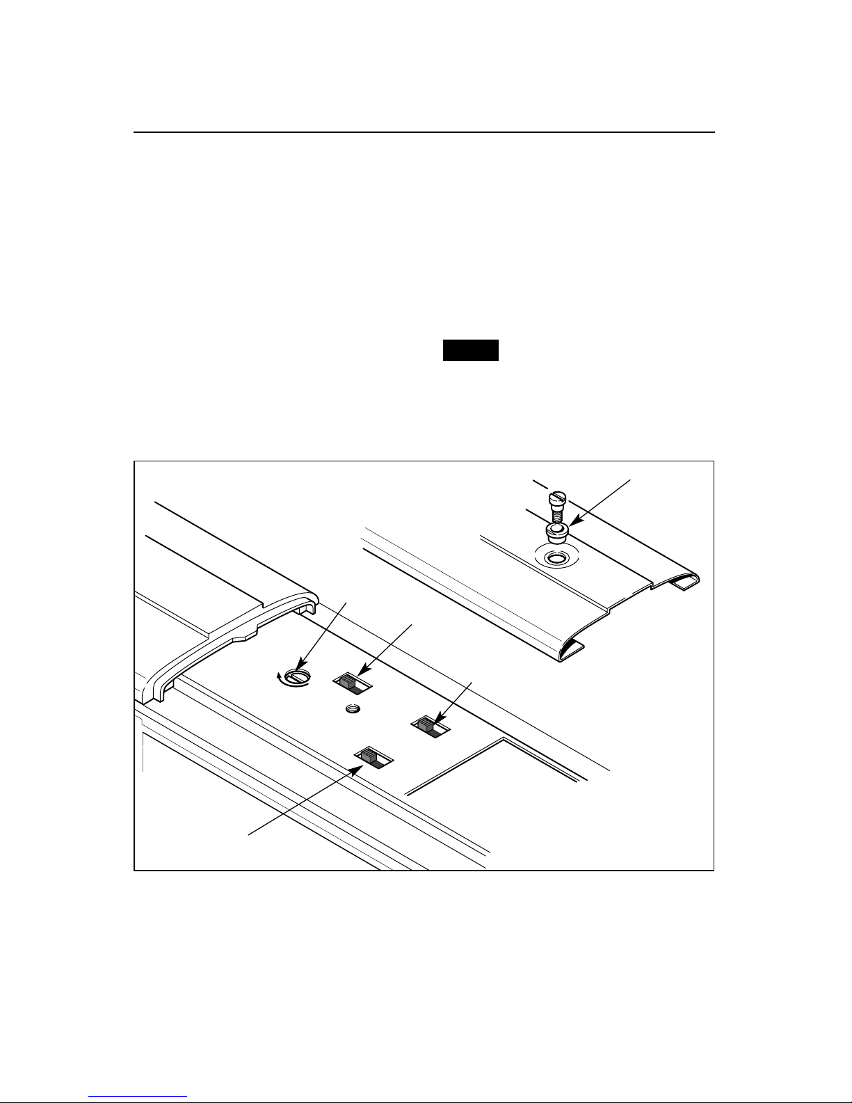
T
o select a single operational state for
your Lionel locomotive (example:
forward only), you can deactivate the
Command reverse unit’s sequencing
function with the reverse unit switch. The
switch is located beneath the locomotive’s
roof panel. To access the switch, remove the
two roof screws with a flat head screwdriver
and lift away the roof. Take care not to
disconnect the wire that connects the roof to
the circuit board.
Get your locomotive moving in the
desired direction, then slow it down
without stopping. Set the Command reverse
unit switch to PROG. Refer to Figure 1 for
the location of the switch. The locomotive is
now “locked” into your chosen direction. Be
sure to replace the insulating washers with
the screws.
When you no longer want single-direction
operation, just slide the Command reverse
unit switch back to RUN.
Your locomotive’s reverse unit
will “reset” to forward after any
power interruption lasting five
seconds or longer, regardless of
the original locked-out direction.
Locking your locomotive into a single operational state
Transformer operations
Figure 1. Switch locations
4
SS
RS
OFF
ON
-
+
PROG
RUN
Note!
Insulating
washer
Smoke unit
switch
Volume
control
Command
reverse
unit switch
RailSounds/
SignalSounds
switch
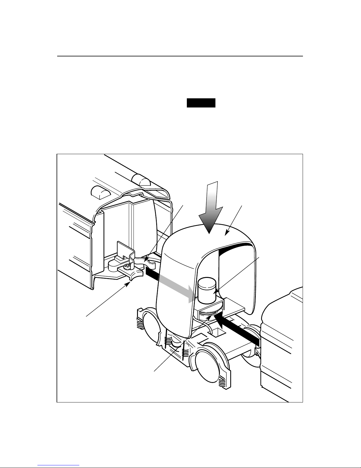
T
rue to the prototype, the Lionel M-10000
features cars that are connected at
shared trucks. Connect a vestibule to one of
the cars at each articulation by pushing the
vestibule assembly into the end of the car.
The clasp slides over and catches the brass
ring, and the contacts lock around the post.
Next, arrange the cars on the track and,
holding them horizontally, slide the
vestibules into the ends of the cars. Once
again, the clasp will catch the brass ring
and the contacts will lock around the post.
Be sure track power is off
before coupling the cars to
prevent accidental short
circuits.
Coupling your M-10000
5
Transformer operations
Figure 2. Coupling the M-10000
Brass ring
Clamp
Vestibule
Contact
post
Contact
Caution!
Transformer operations
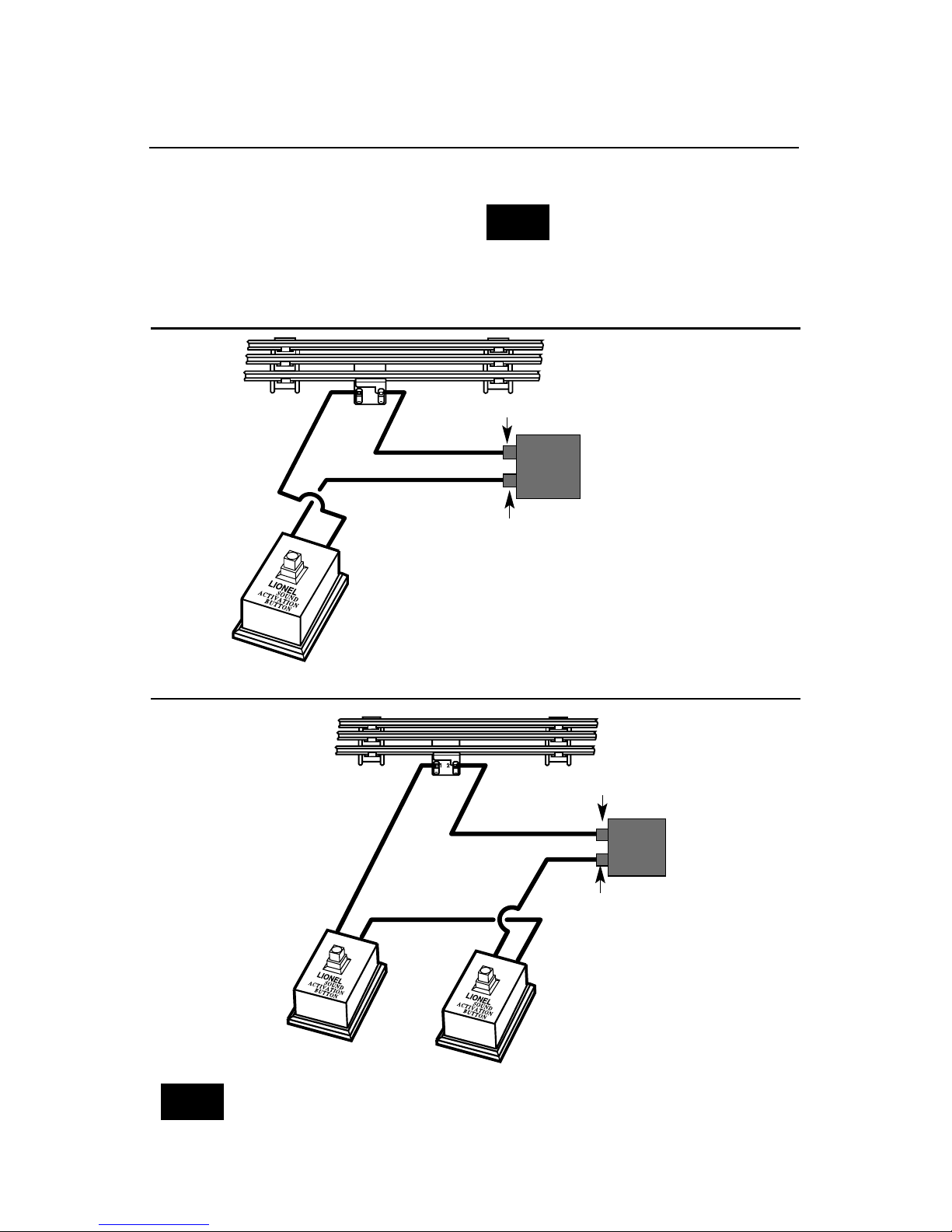
Installing a Lionel Sound Activation Button
12
POWER
SUPPLY
POWER
SUPPLY
For AC transformers with a horn/whistle button
For AC transformers lacking a horn/whistle button
Existing wire
Black wire
Red wire
Lionel no. 610-5906-001
Sound Activation Button for
activating the bell
Lionel no. 610-5906-001
Sound Activation Button
for whistle
Lionel no. 610-5906-001
Sound Activation Button for bell
Black wire
Red wire
Red wire
The no. 610-5906-001 button works with any Lionel AC transformer except
no. 6-4690 Type MW. Transformers made by other manufacturers may not be
compatible with RailSounds.
Note!
T
o activate the bell and horn sounds when
operating your locomotive with
conventional transformers, you’ll need to
install a Lionel no. 610-5906-001 Sound
Activation Button (available separately).
Connect the button(s) as shown below.
All track power must feed through
the Sound Activation Button. Do
not bypass the button.
Note!
Existing wire
Common/Ground/U
Power/A
Common/Ground/U
Power/A
6
 Loading...