

Lionel Overland Freight Express Owner's Manual
Lionel
Overland Freight Express
Owner’s Manual
73-1989-250
8/04
®
SYSTEM
featuring
and

Congratulations!
2
C
ongratulations on your purchase of the ready-to-run Overland Freight Express Train Set!
This set features everything you need to get started—a mighty CW-80 Transformer, a CAB-1
Remote Controller and Command Base, a huge loop of easy-to-assemble FasTrack track, a string
of detailed cars, and a powerful Command Control-equipped Lionel locomotive.
Have fun growing with this complete train set! Start with the set components, then follow your
imagination into your own miniature world. Expand your railroad empire with additional
FasTrack track sections, enhance your layout with accessories, lengthen your consist with extra
cars, or operate a new locomotive at the head end of your train! Explore the possibilities at your
authorized Lionel dealer.
Use this Owner’s Manual to learn how to set up, operate, and maintain your train set for years
of reliable operation.
The following Lionel marks may be used throughout this instruction manual and are protected under law.
All rights reserved.
Lionel
®
, TrainMaster®, Odyssey®, RailSounds®, CrewTalk™, TowerCom™, DynaChuff™,
StationSounds
™
, Pullmor®, ElectroCoupler™, Magne-Traction®, CAB-1®Remote Controller,
PowerMaster
®
, Lionel ZW®, ZW®, PowerHouse®, TMCC®, Lionelville™, Lockon®, Wireless Tether
™
The name FasTrack®is used with permission from Pitsco, Inc.
Overland Freight Express Train Set Inventory
• SD-70MAC diesel locomotive
• Two Maxi-Stack intermodal cars
• Three auto carriers
• Standard O extended vision caboose
• Seven straight FasTrack track sections
• 16 O-60 curved FasTrack track sections
• FasTrack terminal section
• TMCC Command Base
• TMCC CAB-1 Remote Controller
• CW-80 Transformer
• Smoke fluid
• Traction tires
• CAB-1 Remote Controller overlay
• Owner’s Manual

Features of the locomotive
• TrainMaster Command Control equipped—able to run in the TrainMaster
Command Control environment or in the conventional environment with
only a standard transformer
• RailSounds sound system with CrewTalk communication and TowerCom
announcements
• Odyssey System for speed control
• Directional lighting including operating LED headlights
• Operating marker lights
• Two ElectroCouplers
• Dual powerful maintenance-free motors with momentum flywheels
• Four traction tires
• Fan-driven smoke unit
• Lighted number boards
• Lighted cab interior
• Minimum curve: O-31
3
The transformer included with this set should be periodically
examined for conditions that may result in the risk of fire,
electric shock, or injury to persons (such as damage to the
output cord, blades, housing, or other parts). In the event that
such conditions exist, the transformer should not be used until
properly repaired.
Parents!

4
Creating your layout
Operating your CW-80 Transformer safely 5
Building your Lionel layout 6
Joining the FasTrack track section 6
Wiring your CW-80 Transformer 7-8
TrainMaster Command Control operations
TrainMaster Command Control operations 9
Installing batteries in the CAB-1 Remote Controller 9
Operating your locomotive in the Command Control environment 10
CAB-1 Remote Controller commands 11
CAB-1 Remote Controller numeric keypad commands 12
Tuning your locomotive’s performance 13-14
Assigning your locomotive a new ID# 14
Building a lash-up 15
Reprogramming your locomotive to restore features 16
RailSounds sound system operations
RailSounds sound system operations 17
Installing the battery 17
Using the RailSounds sound system in the TrainMaster Command Control environment 18
Using the RailSounds sound system in the conventional environment 19
Odyssey System operations
Odyssey System operations 20
Odyssey System Command Control operation 20
Activating the Odyssey System in the conventional environment 21
Turning off the Odyssey System in the conventional environment 21
Conventional transformer operations
Conventional operations 22
Operating your locomotive in the conventional environment 23
Experiencing the features of the CW-80 Transformer 24-25
Locking your locomotive into a single direction 26
Uncoupling your locomotive in the conventional environment 27
Maintaining and servicing your locomotive
Adding fluid to your locomotive’s smoke generator 28
Lubricating your locomotive 29
Replacing your locomotive’s LEDs and lamps 30
Replacing the traction tires 30
Running your train
Coupling 31
Stacking the containers 32
Expanding the Maxi-Stack into a unit train 33-35
Replacing the lamp in your extended vision caboose 36
CW-80 Transformer operation
Powering your layout with the CW-80 Transformer 37
Setting the accessory output 38
Advanced connections: powering two isolated blocks with two transformers 39
Limited Warranty/Lionel Service 40
Table of contents

5
Operating your CW-80 Transformer safely
Y
our Lionel CW-80 Transformer is listed by Underwriter’s Laboratory Inc. and has been
carefully designed to ensure peak performance. When using electrical products, basic
safety precautions should be maintained.
Be sure to observe the following guidelines:
• Read the manual thoroughly before using this device.
• This device is not recommended for children under eight years of age.
• Parents should periodically inspect this product for potential hazards and, if necessary, have
them repaired by an authorized Lionel Service Center. In the event that such a condition
exists, the transformer should not be used until it has been properly repaired.
• The CW-80 Transformer is intended to be used indoors. Do not use this device if water is
present. Serious or fatal injuries may result.
• Use the CW-80 Transformer only for its intended purpose.
• The CW-80 Transformer was meant to operate on 120-volt, 60-Hertz power. Do not connect
this product to any other power supply.
• Do not operate the CW-80 Transformer with a damaged cord, plug, or case.
• To avoid the risk of electrical shock, do not disassemble the unit. There are no user
serviceable parts inside. If damaged, take this product to an authorized Lionel Service
Center. A list of authorized Service Centers is packed with this unit.
• Do not operate the CW-80 Transformer on your layout unattended. Obstructed accessories or
stalled trains may overheat, resulting in damage to your layout.
• Always unplug the CW-80 Transformer from the power source when not in use.
• Never insert objects into the ventilation slots on this product. Damage to sensitive
electronic components can result.
Creating your layout
6
Joining the FasTrack track sections
F
asTrack track sections join together easily. With interlocking roadbed sections and large rail
tabs, the track fits together securely so you always get good electrical contact. Take a look at
Figure 2 to see how to join the track sections.
1. Line up your two sections of track.
2. Insert the rail tabs into the openings at the ends of the corresponding
rails.
3. Press the sections together until the interlocking roadbed snaps into
place.
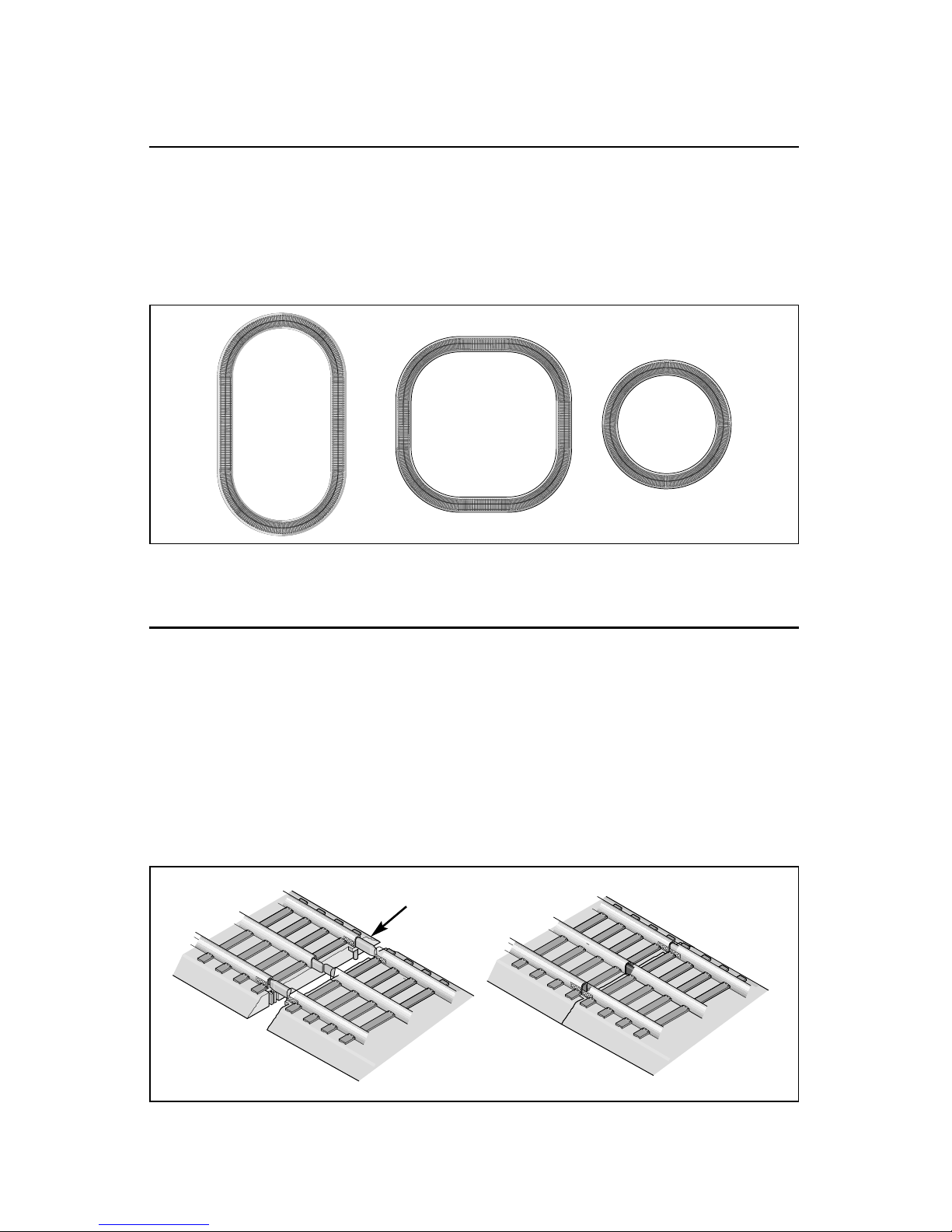
Figure 2. Joining the track sections
Building your Lionel layout
Y
our set comes with sixteen curved, seven straight, and one terminal section of track.
Figure 1 provides some examples of layouts that you can build with these track sections.
By adding more FasTrack track sections, you can create an endless number of exciting track
arrangements for more fun, action, and variety. The railroad empire of your dreams can quickly
become a reality!
Creating your layout
Figure 1. Track layout ideas
Rail tab

7
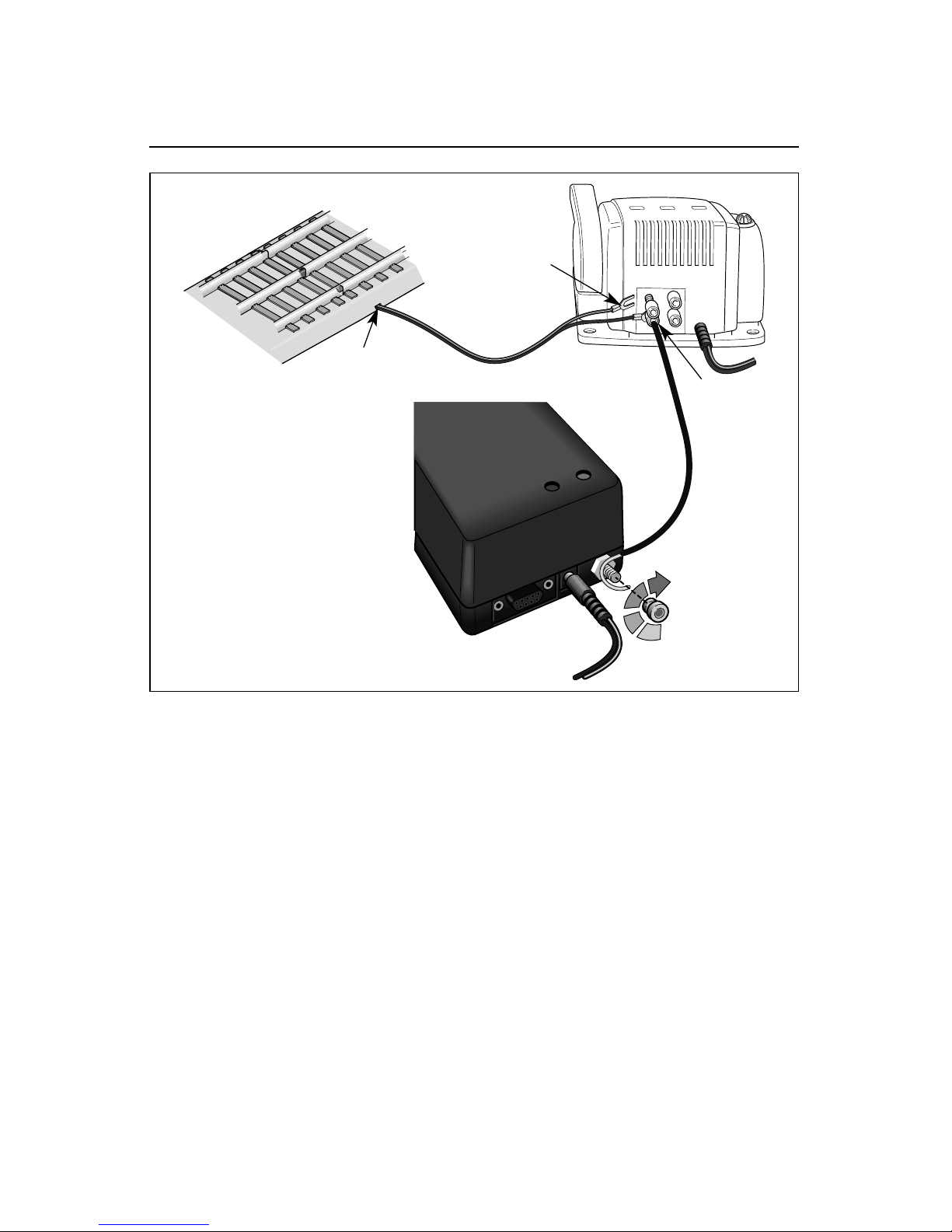
Wiring your CW-80 Transformer
Creating your layout
C
onnect your FasTrack terminal section and your TMCC Command Base to the CW-80
Transformer. Make sure that all connections are secure. Loose connections can produce
extremely high temperatures. For this reason, do not touch the terminals or track connections
during use. Also, do not locate scenery materials such as lichen or ground foam near the
terminals.
1. Feed the wires through the notch in the FasTrack terminal section. Refer to
Figure 3 on page 8.
2. Loosen the red TRACK thumbscrew terminal, then slide the red
spade-shaped connector into position. The thumbscrew post should be positioned
between the “blades” of the spade connector. Be sure that the blades are touching the metal
post. Tighten the thumbscrew to secure the connection.
3. Loosen the black TRACK thumbscrew terminal, then slide the black
spade-shaped connector into position. Tighten the thumbscrew to secure the
connection. The thumbscrew post should be positioned between the “blades” of the spade
connector. Be sure that the blades are touching the metal post.
4. Attach the bare end of the green wire to the TRACK U terminal on the
Command Base and connect it to the black TRACK thumbscrew terminal
on the transformer. This terminal is shared with the black spade-shaped connector.
5. If you need to power an accessory (available separately at your
authorized Lionel dealer), connect the accessory to the ACCESSORY
thumbscrew terminals. Use the accessory wire included with the CW-80 Transformer.
6. Plug the CW-80 Transformer into your wall outlet (120 volts).
As your layout expands, you may also make power connections with the stripped ends of
wires, placing no more than two wires on each terminal. For best performance on large
layouts, it is recommended that you use 16-gauge wire to connect your CW-80 Transformer to
the track. On larger layouts where several track connections are required, the use of separate
junctions/terminal strips (available at your local electronics store) is recommended to prevent
voltage drops.
To prevent the excessive build up of heat, be sure to select the proper wire gauge
for your layout. Follow these guidelines:
• Track connections must be made with 18-gauge wire or heavier. Larger layouts
require a minimum of 16-gauge wire.
• Use 24-gauge wire only when connecting single accessories that require lower
current.
• When wiring multiple accessories (two or more) or accessories that require
higher current, be sure to use 18- to 16-gauge wire.
Caution!
8
Creating your layout
Wiring your CW-80 Transformer (continued)
U
120/60z
0~18VAC
A
B
U
0~18VAC
TRACK
ACCESSORY
C
O
M
P
U
T
E
R
B
A
S
E
P
W
R
T
R
A
C
K
U
Figure 3. Controller connections
FasTrack terminal section
Command Base
CW-80 black
track post
Notch
Spade-shaped
connector
9
TrainMaster Command Control operations
TrainMaster Command Control operations
T
rainMaster Command Control is the advanced model railroad control system from Lionel. To
operate your locomotive in the Command Control environment, your
Command Base must be connected to the U terminal on your transformer.
Your commands are sent by the CAB-1 Remote Controller to the Command Base, which then
translates the command into digital code. That code is sent through the outside rails to your
locomotive, which will not respond until it recognizes its unique ID#. TrainMaster Command
Control gives you the power to operate multiple Command-equipped locomotives on the same
track at the same time.
Keep in mind that track power is like gasoline in the tank of a car—it gives you the power
to go places, but it doesn’t tell you where to go or how fast to get there.
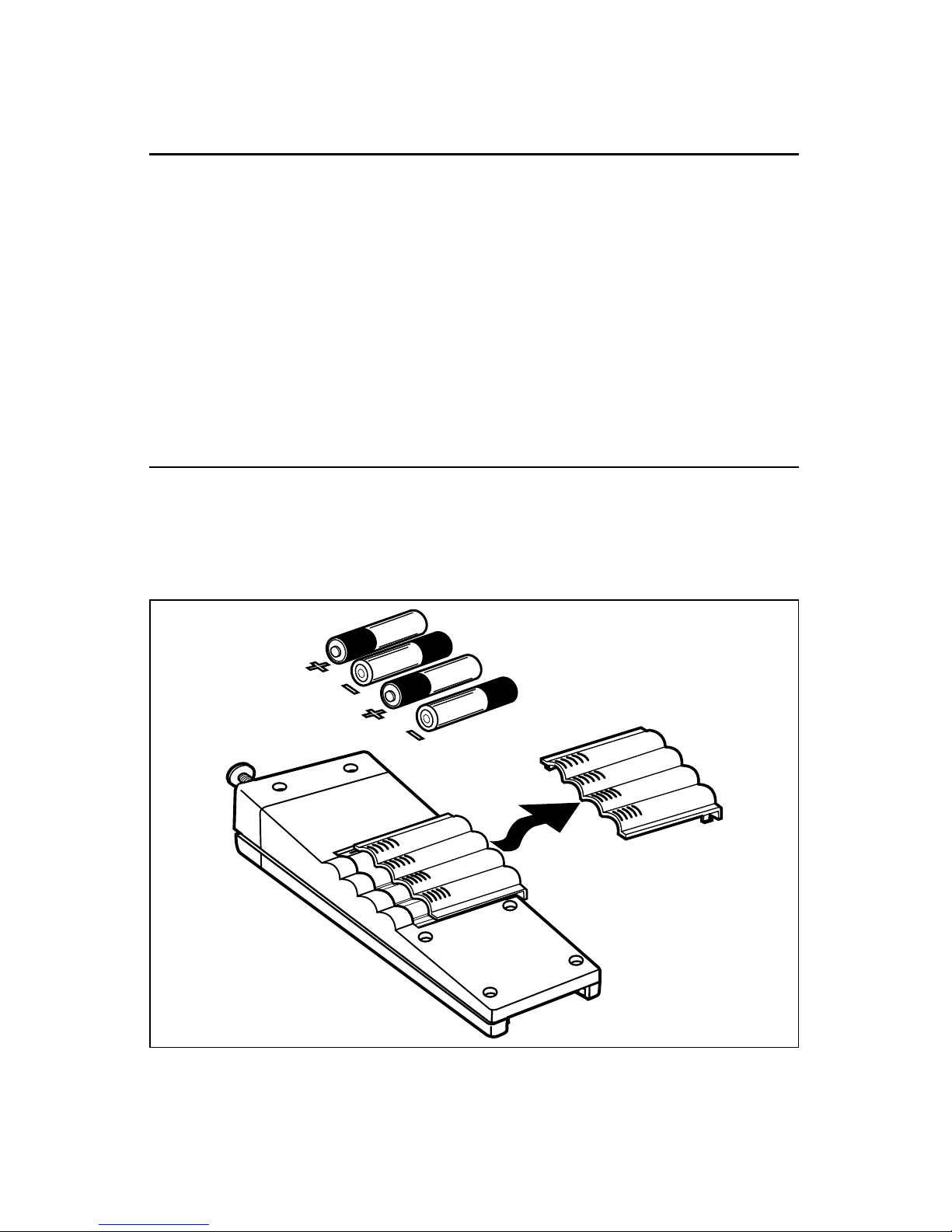
Installing batteries in the CAB-1 Remote Controller
Y
our CAB-1 Remote Controller requires four alkaline AA batteries (not included). To install
to batteries, simply slide off the back cover and place the batteries in the battery
compartment. Refer to Figure 4. Be sure that the + terminals on the batteries correspond with
the + terminals in the battery compartment.
Figure 4. CAB-1 Remote Controller battery installation

10
TrainMaster Command Control operations
Operating your locomotive in the Command Control environment
1. Turn off track power and plug-in the Command Base. Be sure that the
Command Base is connected to the outside rail or to the Common/Ground/U terminal on
your track power supply.
2. Place your locomotive on Lionel or Lionel-compatible O-31 or larger
track.
3. Increase track voltage to full power (19 volts AC). Use the orange throttle lever
on your CW-80 transformer.
4. Press ENG and enter the ID# to address your locomotive with your CAB-1
Remote Controller. All Lionel locomotives come factory-programmed as ID# 1. To
change the ID#, see page 14.
5. Throttle up and move ‘em out! Your locomotive will respond to every command from
your CAB-1 Remote Controller.
11
TrainMaster Command Control operations
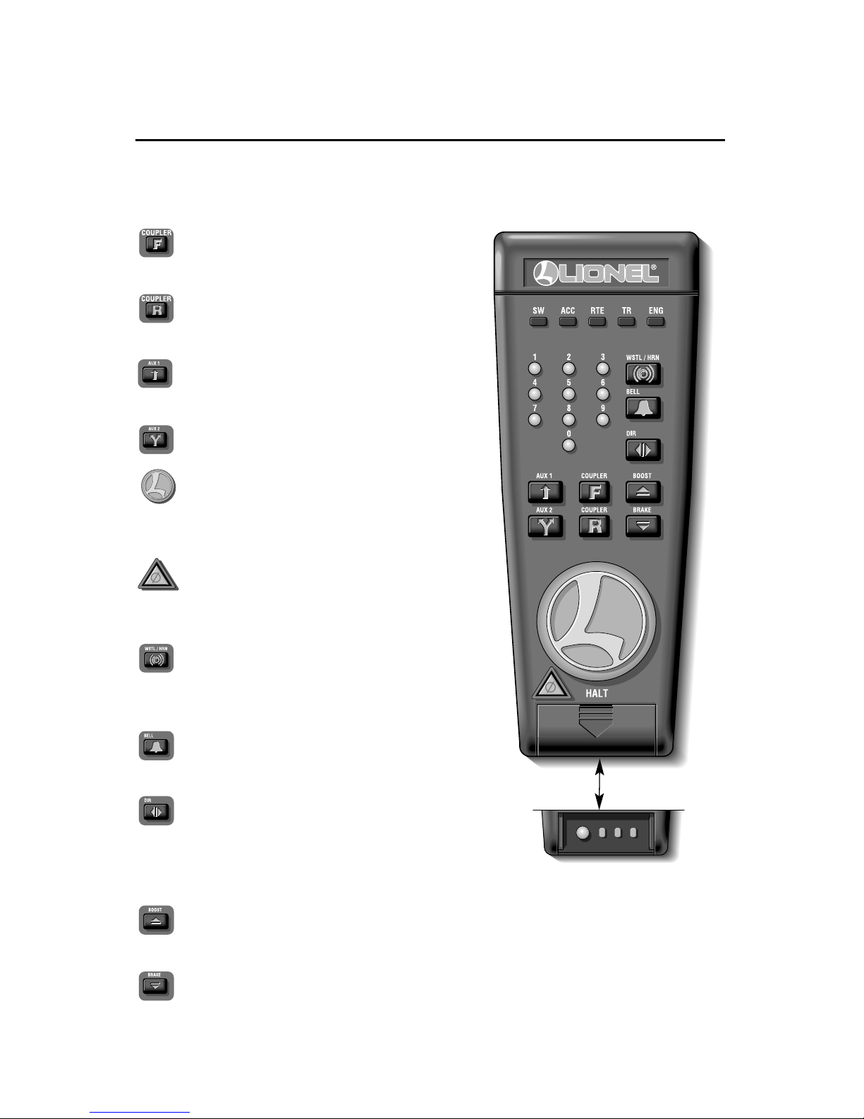
CAB-1 Remote Controller commands
T
he CAB-1 Remote Controller commands are detailed below. The corresponding
RailSounds sound system effects are in bold italic type.
Releases the front coupler.
Coupler release sound.
Releases the rear coupler.
Coupler release sound.
Activates the numeric keypad.
Air release sound.
Toggles the headlight on and off.
Accelerates the locomotive with a clockwise
rotation. Decelerates the locomotive with a
counter-clockwise rotation.
Stops all TrainMaster Command Control-
equipped locomotives in operation. Use HALT
only in emergency situations.
Activates the locomotive’s horn. Release the
button to discontinue the sound. Multihorn
diesel horn sound.
Toggles the bell sound on and off. Mechanical
bell sound.
Changes the locomotive’s direction. The locomotive
decelerates to a stop and continues in the opposite
direction when you increase the throttle.
Air release sound.
Increases the locomotive’s speed while the button is pressed. Release the button to return
to the initial speed.
Decreases the locomotive’s speed while the button is pressed.
Squealing brake sounds.
SET L M H
See page 13 for the
momentum settings
12
TrainMaster Command Control operations
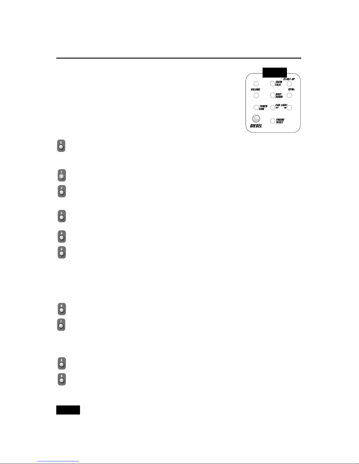
CAB-1 Remote Controller numeric keypad commands
W
hen you press the AUX1 button on your CAB-1 Remote Controller,
you turn the numeric keypad into ten command buttons. These
commands are specific to your locomotive, and an overlay is included to
help you learn these functions. After you press the AUX1 button, you will
be able to press any numbered button until you address a different
Command Control equipped product. The corresponding
RailSounds sound system effects are in bold italic type.
Stops and resets the locomotive. Resets the locomotive’s direction to forward. Resets the
RailSounds sound system to automatic RPM operation. Horn blows. RPM sounds
return to automatic.
Raises the volume of the RailSounds sound system. Sound volume increases.
Activates CrewTalk communication, unintelligible radio dialogue. CrewTalk
communication.
Increases the RailSounds sound system RPM level. Starts the RailSounds sound system.
RPM level increases. Start-up sequence commences.
Lowers the volume of the RailSounds sound system. Sound volume decreases.
Activates the shutdown sequence. Like prototypical locomotives, the RPM level must be at
idle for shutdown to occur. Press 6 repeatedly to lower the RPM level until the RPM sounds
reach idle. Press 5 to initiate the shutdown sequence and listen for the CrewTalk
communication. Keep in mind that the horn, bell, and RPM sounds are inactive until you
restart the RailSounds sound system by pressing 3. CrewTalk communication.
Diesel shutdown sequence.
Lowers the RailSounds sound system RPM level. RPM level decreases.
Activates a TowerCom announcement, which includes a call-out specific to your
locomotive. Pressing AUX1, 7 the first time triggers a “hold for clearance” message. Press
7 again, and a “clear for departure” message plays. There is a four-second delay in this
function. TowerCom announcement.
Turns off the smoke unit. Air release sound.
Turns on the smoke unit if the smoke unit switch is in the ON position. Be sure to add
smoke fluid before turning on the smoke unit to prevent damage to your locomotive. Air
release sound.
AUX1, 8 and 9 function only if the locomotive’s smoke unit switch is in the ON
position.
Note!
➠
➠
➠
➠
AUX1
 Loading...