

Lionel Oil Tank Owner's Manual
73-7966-250
5/11
Lionel
Oil Tank
Owner’s Manual
Lionel
Oil Tank
Owner’s Manual

2
C
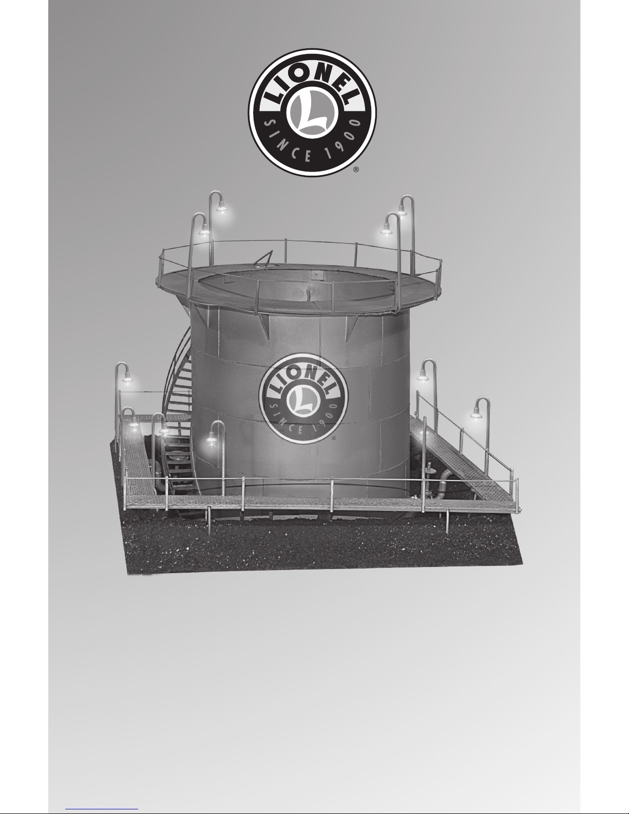
ongratulations on your purchase of the Lionel Oil Tank accessory! Available in spherical
or cylindrical forms, this accessory features a detailed tank, illuminated walkways, and
a detailed base. Place this accessory on your layout by itself, or you may choose to expand by
configuring the base to sit next to additional oil tanks.
Congratulations!
The following Lionel marks are used throughout this catalog and are protected under law. All rights
reserved.
Lionel®, LEGACY™, FasTrack™, TrainMaster®, Odyssey®, RailSounds®, CrewTalk™, TowerCom™,
DynaChuff™, StationSounds™, Pullmor®, ElectroCoupler™, Magne-Traction®, CAB-1® Remote
Controller, American Flyer®, Lionel ZW®, ZW®, MagniVision®, TMCC®, Lionelville®, Wireless
Tether™, Powerhouse™, LionMaster®, Conventional Classics™, Postwar Celebration Series™,
TruRail™, PH-1 Powerhouse®, Powermaster®, Powerstation-Powerhouse®, Accessory Motor
Controller™, AMC™, Accessory Switch Controller™, ASC™, Action Recorder Controller™, ARC™,
Track Power Controller 300™, TPC 300™, Track Power Controller 400™, TPC 400™, Block Power
Controller™, BPC™, Operating Track Controller™, OTC™, FatBoy™, Lionel Lines®, Joshua Lionel
Cowen Series™, Lockon®, TrainSounds™, MultiHorn™, MultiWhistle™, Choo-Choo™
Table of contents
Oil Tank Inventory
Setting up your Oil Tank 3-4
Powering the accessory 5
Joining multiple Oil Tanks together 6
Servicing the lamps 7
Limited Warranty/Lionel Service 8
• Resin base with two removable ends and tank structure
• Two long platform sections with lights*
• Two short platform sections with lights
• Power leads with connector
• On/Off switch
• Owner’s Manual
*One platform has steps and two wire connectors at one end

3
Setting up your Oil Tank
F
ollow the instructions below to install the illuminated walkways around the Oil Tank.
Refer to Figure 1 on page 4.
1. Remove the two pairs of illuminated walkways from the box. Note the difference in the distance
between the posts on the long and short walkway sections.
2. Configure the walkway sections so that the posts match the holes in the base.
3. Connect the wires between the walkways. Insert the posts into the holes in the base.
For ease of installation, connect the walkways before placing them on the base.
4. Plug the connector at the end of the long walkway with steps into the receptacle from under the
base.
5. Plug the second connector on the walkway with steps into the power supply wire plug.
Hint!
 Loading...