

Lionel Kraft/Nabisco Holiday 2002, Area 51 Alien Recovery Owner's Manual
73-1950-250
5/02
CAUTION—ELECTRIC TOY
NOT RECOMMENDED FOR CHILDREN UNDER EIGHT YEARS OF AGE. AS WITH ALL ELECTRIC
PRODUCTS, PRECAUTIONS SHOULD BE OBSERVED DURING HANDLING AND USE TO REDUCE
THE RISK OF ELECTRIC SHOCK.
TRANSFORMER RATINGS—INPUT:120 VAC; 60 HZ ONLY.
AC OUTPUT :20 V; 54 V A
Kraft/Nabisco
Holiday 2002 Train Set
Owner’s Manual

Congratulations!
2
Y
ou’re now the proud owner of the
Kraft/Nabisco Holiday 2002 Train Set.
Everything you need to get started is included.
You’re already off to a great start by reading
this instruction manual. It has important
information on train setup and operation.
This booklet also covers proper maintenance
procedures to help your Lionel trains live
long, healthy lives.
If you have any questions after reading
this booklet, contact your nearest Lionel
Authorized Service Center or call Lionel
Customer Service at 586-949-4100. And
have fun!
Table of contents
Track layout
Joining the track sections 3
Suggested track layouts 4
Attaching the Lock-On to the track 4
Controller operations
Stripping the wire 5
Attaching the controller wires to the Lock-On 6
Controller functions 7
Controller and short circuits 8
Locomotive operation
Running your RS-3 diesel locomotie with a Lionel transformer 9
Reverse unit procedure 10
Lubricating your locomotive 11
Replacing your locomotive’s interior lamp 12-13
Replacing your locomotive’s headlamps 12-13
Train operation
Tire-Traction 14
Coupling 14
Notes 15
Limited Warranty/Lionel Service 16
The transformer included with this set should be periodically
examined for conditions that may result in the risk of fire, electric
shock, or injury to persons (such as damage to the output cord,
blades, housing, or other parts). In the event that such conditions
exist, the transformer should not be used until properly repaired.
Parents!
The following Lionel marks may be used throughout this instruction manual and are protected under
law. All rights reserved.
Lionel®, TrainMaster®, Odyssey®, RailSounds™, CrewTalk™, TowerCom™, DynaChuff™,
StationSounds™, Pullmor®, ElectroCoupler™, Magne-Traction®, CAB-1 Remote Controller®,
PowerMaster®, Lionel ZW®, ZW®, PowerHouse®, TMCC™
Joining the track sections
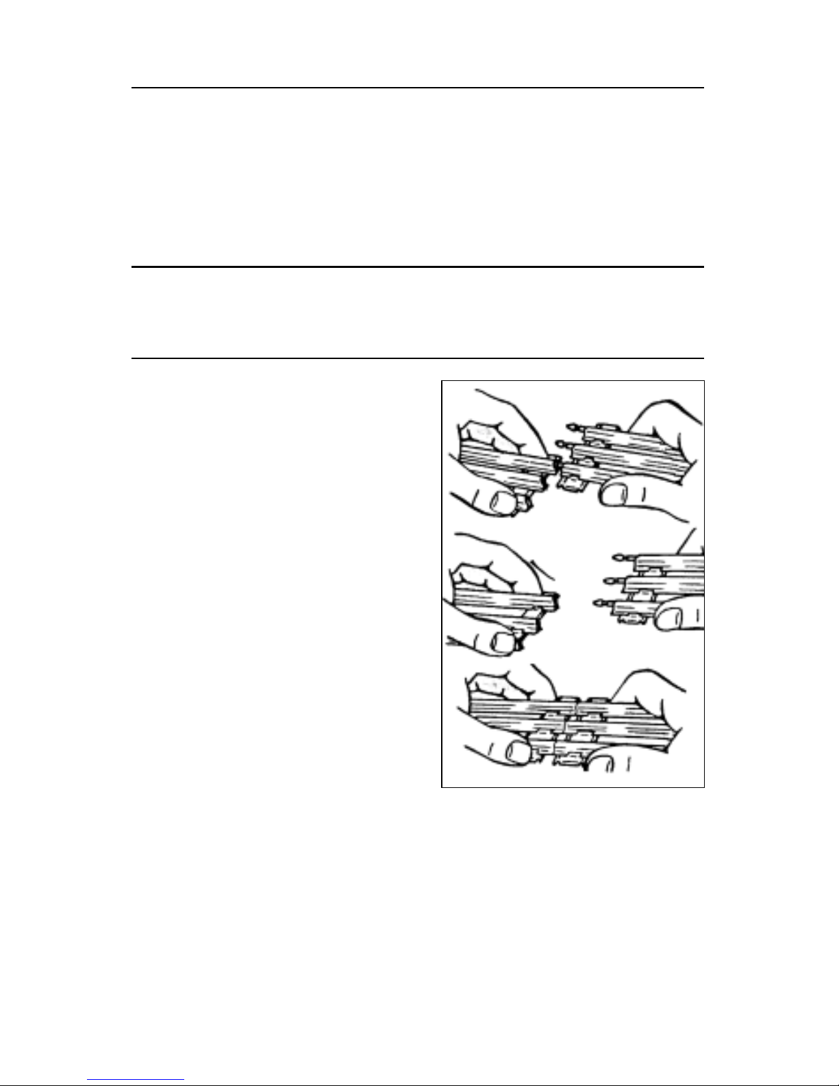
J
oin the track sections together by inserting
the pins of one track section into the open
ends of another. For good electrical contact, the
pins must be carefully inserted and the track
joints tightly fitted.
If the track is difficult to connect, try this
installation tip. You can “break in” O gauge
track sections by inserting and withdrawing a
track pin into one rail at a time before joining
the entire track section as illustrated in Figure 1.
If the openings become too large (causing the
track to fit loosely), pinch the rail together
around a track pin with a pair of pliers. If any
pins fall out of the track and are missing, replace
them with extras available from your Lionel
dealer.
Maintenance tip: The rails should be kept
clean, dry, and free from oil and grease. Clean
rust and dirt spots with a track eraser. Wipe the
track using a cloth dampened with track cleaner
from the Lionel Maintenance Kit (6-62927),
available from your nearest Lionel Dealer.
Track layout
3
Features of the Nabisco RS-3 Freight Set
• Union Pacific RS-3 locomotive
• Nabisco Boxcar
• U.P. Tankcar
• U.P. Caboose
• Controller
• 40-watt power pack
• Lock-On
• Eight pieces of straight track (O-27)
• Eight pieces of curved track (O-27)
• Service Center list
• Railroader Club application
• Warranty Card
Figure 1. “Breaking in” your track
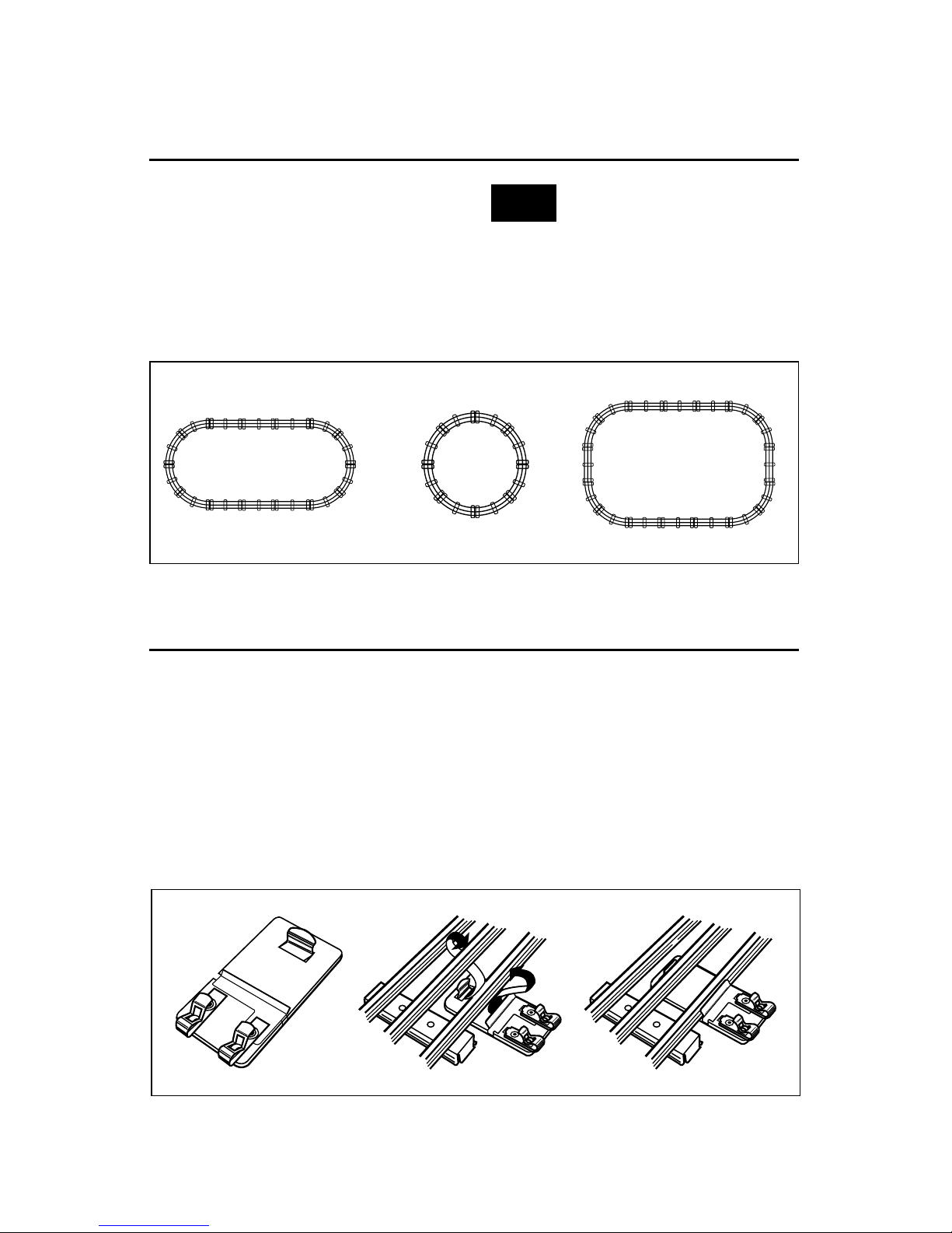
Attaching the Lock-On to the track
T
he Lock-On connects power from your
controller to the track. As illustrated in
Figure 3, attaching the Lock-On to the track
is quick and easy. First, place the Lock-On
under any straight section of track. Fit the
center lip of the Lock-On onto the edge of an
outside rail. Press the Lock-On upward so
that the spring contact snaps onto the center
rail. The Lock-On should face outward when
setting up your track. Make sure it is firmly
connected.
Once the Lock-On is securely attached to
the track, you are ready to insert the wires
from the controller into the two spring clips
on the Lock-On.
2
1
LIONEL
CTC
LOCKON
Track layout
4
Suggested track layouts
F
igure 2 provides some examples of lay-
outs you can build with eight straight
and eight curved sections of track.
Remember—the more track you own, the
more variations you can create in your train
layout. And that means more action and
more fun!
We recommend that you do not set
up your track layout on carpeted
surfaces. Carpet fibers may collect on your
engine’s wheels and drive gears, preventing
your engine from operating properly. For
best results, place the track on a hard
surface.
Figure 2. Track layout ideas
Figure 3. Lock-On installation
Note!
Controller operations
5
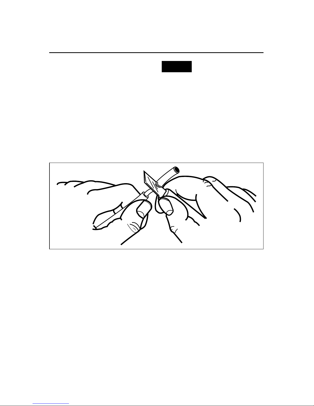
Stripping the wire
O
nce your track is assembled and the
Lock-On is securely attached, you can
connect the wires from the controller to the
Lock-On.
First you’ll want to check the ends of the
wires to make sure that the insulation is
stripped back about 1⁄4˝ to 3⁄8˝. To strip the
wires, use a pair of wire strippers or a sharp
knife as illustrated in Figure 4.
Only an adult should perform
this task! Always use care
when stripping wires.
Figure 4. Wire stripping
Caution!
 Loading...