

Lionel Holiday Special Train Set Owner's Manual
78-1029-250
6/05
Lionel
Holiday Special Train Set
Owner’s Manual
CAUTION—ELECTRIC T O Y
NOT RECOMMENDED FOR CHILDREN UNDER EIGHT YEARS OF AGE. AS WITH
ALL ELECTRIC PRODUCTS, PRECAUTIONS SHOULD BE OBSERVED DURING
HANDLING AND USE TO REDUCE THE RISK OF ELECTRIC SHOCK.
TRANSFORMER RATINGS—INPUT:120 VAC; 60 HZ ONLY; 65W.
AC OUTPUT: 18 V; 2.0A

2
Congratulations!
C
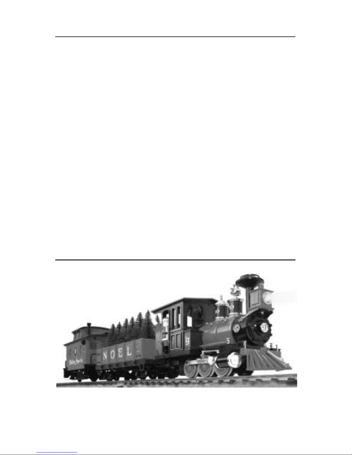
ongratulations on your purchase of the Lionel Holiday Special Train Set! This set features
an 0-6-0 steam locomotive, a gondola with six trees, and a musical caboose.
Read this instruction manual thoroughly for important tips on operating and maintaining
your Large Scale Christmas Set.
• 0-6-0 steam locomotive
• Holiday gondola with six trees
• Musical caboose
• Controller and power pack
• Twelve sections of Large Scale track
• Santa figure
• Five replacement hook-and-loop couplers
• Track Lockon
• Power wire with spade connector
Holiday Special Train Set Inventory
The transformer included with this set should be periodically
examined for conditions that may result in the risk of fire,
electric shock, or injury to persons (such as damage to the
output cord, blades, housing, or other parts). In the event that
such conditions exist, the transformer should not be used until
properly repaired.
Parents!
The following Lionel marks may be used throughout this instruction manual and are protected under law.
All rights reserved.
Lionel
®
, TrainMaster®, Odyssey®, RailSounds®, CrewTalk™, TowerCom™, DynaChuff™,
StationSounds™, Pullmor®, ElectroCoupler™, Magne-Traction®, CAB-1®Remote Controller,
PowerMaster
®
, Lionel ZW®, ZW®, PowerHouse®, TMCC®, Lionelville™, Lockon®, Wireless Tether™,
LionMaster
®
, FatBoy™, American Flyer®, TrainSounds
™
The name FasTrack®is used with permission from Pitsco, Inc.
3
Table of contents
Track assembly and layout
Joining the track sections 4
Powering your set 5
Controller operations
Operating your Transformer safely 6
Operating the controller 7
Controller and short circuits 8
Train operations
Installing the Santa figure 9
Coupling the cars 10
Installing and operating the hook and loop couplers 11
Operating your musical caboose 12
Maintaining your set
Replacing the lamp 13
Maintenance and lubrication 14
Notes 15
Limited Warranty/Lionel Service 16
Holiday Special Train Set Features
Bright
headlight
Santa
figure
Operating couplers
Six trees
Musical
caboose
4
Track assembly and layout
J
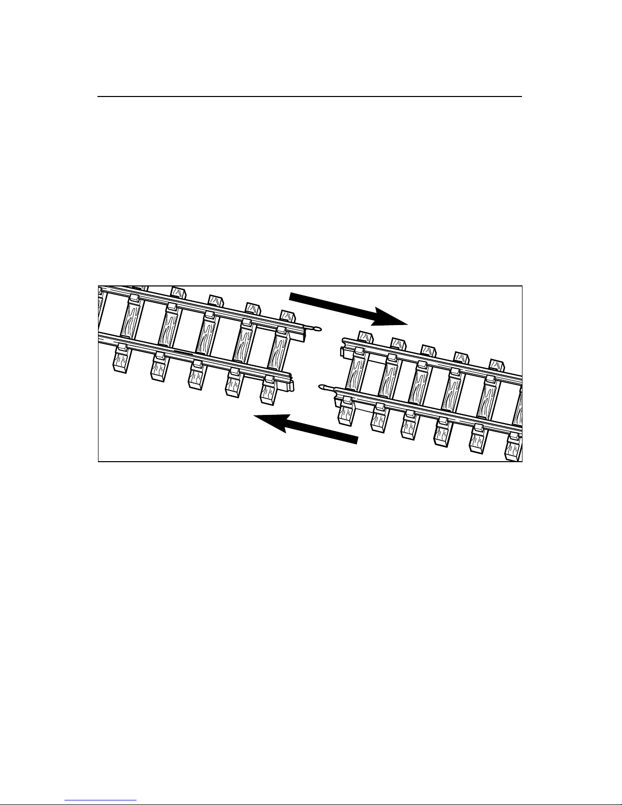
oin the track sections together by inserting the pins of each track section into the rail
openings of another section. Refer to Figure 1. Pins must be fully inserted and track joints
tightly fitted for good electrical contact. The plastic track sections snap together to assure
correct assembly. If the rail openings have become enlarged and fit together loosely, pinch the
rail around a track pin with a pair of pliers. If any pins fall out of the track, be sure to replace
them.
The rails should be kept clean, dry, and free from oil and grease. Remove tarnish and dirt
spots with any commercial brass cleaner or non-abrasive metal polishing pad to keep your track
in top condition. Wipe the track with a clean soft cloth dampened with track cleaner from the
Lionel Lubrication and Maintenance Set (6-62927).
Joining the track sections
Figure 1. Track assembly

Track assembly and layout
Powering your set
T
he Lockon connects power from your
controller to the track. Attaching the
Lockon to the track is simple. First, place
the Lockon under any section of track. Fit
the flange of the outside rail into the
squared brass contact on the Lockon. Press
the Lockon upward so that the spring
contact snaps onto the inside rail. The
Lockon terminals should be located on the
outside of your loop of track. Refer to
Figure 2.
Squared brass
contact
Spring contact
Inner rail
Lockon
Brass
flange of
outer rail
To connect the wires to the Lockon, press down
the upper half of the spring clip until the metal
loop in the lower part projects through the top.
Insert the stripped end of the wire into the loop
and release the clip. See Figure 3. Spring
tension will hold the wire tight.
Next, connect the spade-shaped connectors
at the ends of the wire to the thumbscrew
terminals on the back of the controller.
Loosen the thumbscrew and position the
post between the “blades” of the spade
connector. Be sure that the blades are in
contact with the thumbscrew post. Tighten
the thumbscrew to secure the connection.
Refer to Figure 4. Plug the wall pack into
any standard outlet and plug the end into
the jack in the back of the controller. See
Figure 5 on page 7.
Figure 4. Power connection
Figure 3. Wire connections
Figure 2. Attaching the Lockon
5
 Loading...