

Lionel Halloween Witch Pylon, Helicopter Pylon Owner's Manual
Lionel
Halloween Witch Pylon
Owner’s Manual
1
Lionel
Halloween Witch Pylon
Owner’s Manual
71-4297-250
3/07

C
ongratulations on your purchase of the Lionel Halloween Witch Pylon! Watch as the witch
circles the tower.
Congratulations
• Pylon
• HalloweenWitch
• Supportarm
• Switch
• Threegreenwires
• Owner’sManual
Halloween Witch Pylon Inventory
Wiring your Pylon with a conventional power supply 3-4
Installing your Pylon 5
Attaching the witch to your Pylon 6
Operating your Pylon with a conventional power supply 6
Operating your Pylon with TrainMaster Command Control 7-8
Replacing the lamp in your Pylon 9-11
Limited Warranty/Lionel Service 12
Table of contents
2
The following Lionel marks may be used throughout this instruction manual and are protected under
law. All rights reserved.
Lionel®, TrainMaster®, Odyssey®, RailSounds®, CrewTalk™, TowerCom™, DynaChuff™,
StationSounds™, Pullmor®, ElectroCoupler™, Magne-Traction®, CAB-1® Remote Controller,
PowerMaster®, Lionel ZW®, ZW®, PowerHouse®, TMCC®, Lionelville™, Lockon®, Wireless
Tether™, LionMaster®, FatBoy™, American Flyer®, TrainSounds™, PowerMax
™
The name FasTrack® is used with permission from Pitsco, Inc.

W
iring your accessory is the first step in preparing for flight. The Pylon will operate best
at 12-18 volts (AC), and it can be powered through track power with a Lionel Lockon
(available separately, 6-62900), or a FasTrack Accessory Power Wire (available separately,
6-12053), OR through an accessory power supply. We recommend that you choose a power
supply that will allow you to increase or decrease the voltage to the accessory. Changing the
voltage allows you to control the speed at which the witch circles the pylon. Figure 1 on page 4
illustrates the following procedure.
To make proper connections, you need the insulation at the ends of the wires to be stripped
back 1/4” to 3/8”. To strip the wires, use a pair of wire strippers.
Only an adult should perform this task! Always use care when stripping wires.
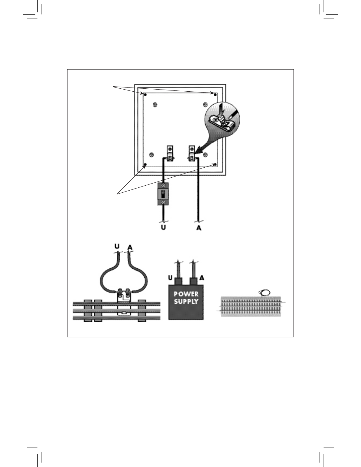
1. Attach one wire to the #1 terminal of the track Lockon, a FasTrack Accessory Power Wire,
OR the Power/A terminal on the accessory power supply. Connect it to one of the terminals
on the separate switch (included with this accessory).
2. Attach an additional wire to the other terminal on the switch. Connect the other end of this
wire to one of the spring-clip terminals at the bottom of the pylon.
To make the spring-clip terminal connections, press down on the “springy” top of
the terminal clip so that a metal loop is formed. Slide the bare end of the wire into
the exposed loop. Release pressure on the terminal clip, allowing the crimped metal
to pinch the end of the wire in the metal loop. Give a little tug on the wire to check
if the hold is secure.
3. Attach another wire to the #2 terminal of the track Lockon, a FasTrack Accessory Power
Wire, OR the Common/Ground/U terminal on the accessory power supply. Connect it
directly to one of the spring-clip terminals at the bottom of the pylon.
At this point, your accessory is wired for power. See page 6 for how to operate this accessory
with a conventional (non-TrainMaster Command Control) power supply.
Wiring your Pylon with a conventional power supply
3
Caution!
Note!
4
Mounting
holes
Mounting
holes
Figure 1. Wiring for conventional operation
Wiring your Pylon with a conventional power supply
(continued)
FasTrack Accessory Power Wire
 Loading...