

Lionel Barrel Shed Owner's Manual
71-6881-250
09/09
Lionel
Lionel
Barrel Shed Owner’s
Barrel Shed Owner’s
Manual
Manual

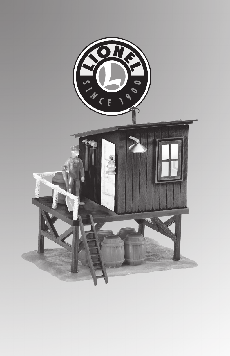
Congratulations!
ongratulations on your purchase of the Lionel Barrel Shed! This accessory features
C
Interior lighting, and rustic decoration.
Table of contents
Wiring your accessory for conventional (non-Command) operation 3
Wiring and operating your accessory with TrainMaster Command Control 4
SC-2 wiring and operation 4
Accessory Switch Controller wiring and operation 5
Replacing the lamp 6
Chimney installation 7
Limited Warranty/Lionel Service 8
The following Lionel marks may be used throughout this instruction manual and are protected under
law. All rights reserved.
®
Lionel
, TrainMaster®, Odyssey®, RailSounds®, CrewTalk™, TowerCom™, DynaChuff™, StationSounds™,
®
Pullmor
ZW
American Flyer
RailSounds
, ElectroCoupler™, Magne-Traction®, CAB-1® Remote Controller, PowerMaster®, Lionel ZW®,
®
, PowerHouse®, TMCC®, Lionelville™, Lockon®, Wireless Tether™, LionMaster®, FatBoy™,
®
, TrainSounds™, PowerMax™, LEGACY™, PowerMax™ Plus, Odyssey II™, LEGACY
™
, FasTrack
™
2
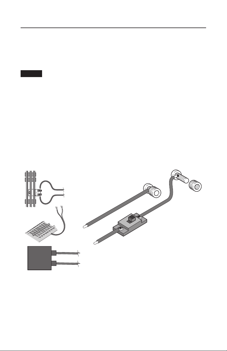
Wiring your accessory for conventional (non-Command) operation
our accessory operates best at 12-18 volts (AC). As illustrated in Figure 1, you may connect
Y
the accessory to a separate power supply or to a Lionel Lock-On (available separately,
6-62900) connected to your track. You will need the ends of the wires to be stripped back 1/4”
to 3/8”.
Caution!
should perform this task! Always use care when stripping wires.
1. Attach one wire to one of the thumb screw terminals. Connect it to the Power/A terminal
on your power supply OR to the #1 terminal on your Lock-On.
2. Attach another wire to the remaining thumb screw terminal. Connect it to one of the
terminals on the small switch included with this accessory.
3. Attach another wire to the remaining switch terminal. Connect it to the Common/
Ground/U terminal on the power supply OR to the #2 terminal on the Lock-On.
Slide the switch to the ON position to activate the light.
To strip the wires, use a pair of wire strippers or a sharp knife. Only an adult
U
A
U
A
To Lock-On or Power Supply
Accessory Power Terminals
U
POWER
SUPPLY
A
Figure 1. Power connections
3
 Loading...