

Page 1
Warning: Use only water or an
appropriate antifreeze. Do not use any
other liquids especially methanol,
automotive antifreeze or any kind of oil.
Do not exceed 50% antifreeze.
LION
TM
BOILERS
CEBR2 Series Boiler
Installation Manual
CEBR2 V7.0 Printed in Canada
Page 2
2
Page 3

Before You Begin
Please read this manual thoroughly before you begin. If you encounter problems please
see the troubleshooting section near the end of this manual. This boiler should only be
installed and tested by qualified personnel with experience in hydronic heating
systems, and electrical installations. This boiler should not be modified or altered in
any manner. Any modification or alteration may cause the boiler to malfunction and
cause serious damage and injury, and will void the manufacturers warranty.
The installation of this boiler must comply with all local regulations
and codes. Verify the “Name Plate” rating to properly size
conductors, and overcurrent protection.
(1)Before installation, ensure that the local electrical inspection authority will
accept connection of this boiler to the existing panel.
(2)This boiler may only be installed and tested by qualified personnel.
(3)The electrical power supply should be checked for adequacy for the additional
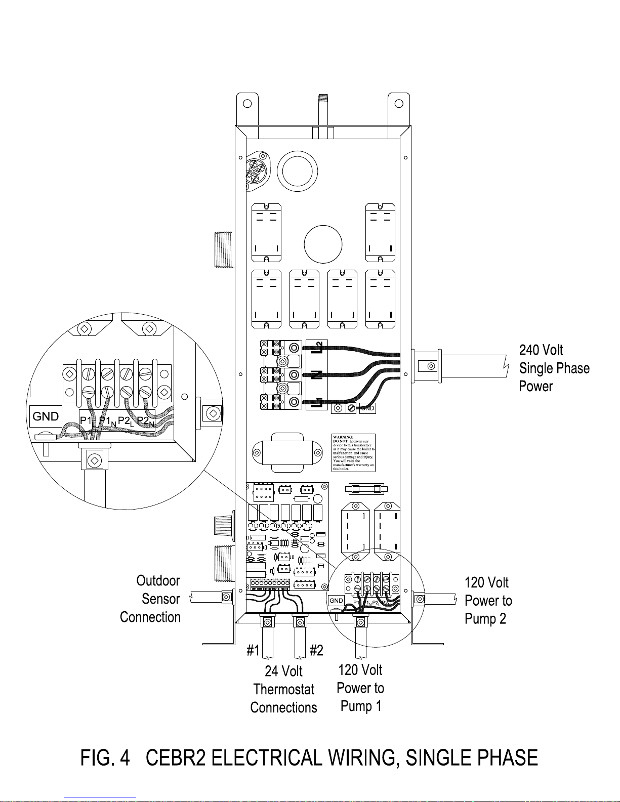
load of the boiler. 240 volt models require connection of 240 volt single phase
power to terminals L1 and L2, and connection of a neutral conductor to the N
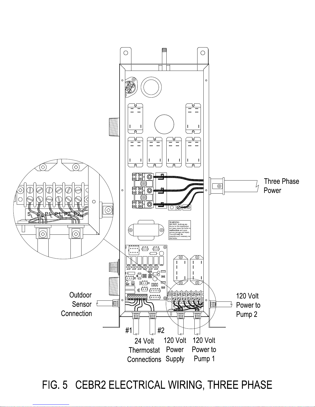
terminal (see Fig. 4). Three phase models require connection of three phase
power of the correct voltage to the L1, L2, and L3 terminals, and a 120 volt 15
amp supply to the terminals SL and SN (see Fig. 5).
Introduction
Your Electric Boiler has been designed to exacting specifications to provide controlled
efficient heating and maximum service life. The boiler is controlled internally by an
electronic control board. The boiler is energized when one of the external thermostat
wired to the control board calls for heat. The circulation pump is started first to
provide flow through the heating system, then the heating elements are staged on as
required. A temperature sensor mounted in the tank monitors the water temperature,
and the internal control board maintains the temperature of the water exiting the
boiler by staging the elements on or off as required. This is know as modulating. The
temperature is set by the aquastat control on the side of the boiler. The modulating
control strategy built into the control board uses only the minimum number of
elements necessary to maintain the desired temperature, resulting in maximum
comfort.
3
Page 4
Outdoor Reset Control
This model also has Outdoor Reset control. An outdoor temperature sensor is used to
monitor the outside temperature. The electronic controls then regulate the water
temperature based on both the aquastat setting and the outside temperature to fine
tune the boilers heat output. As the temperature outside increases, the boiler control
will decrease the target water temperature set on the aquastat. By modulating the
boilers heat output based on both the indoor and outdoor temperature, your CEBR2
model provides you with the ultimate in indoor comfort.
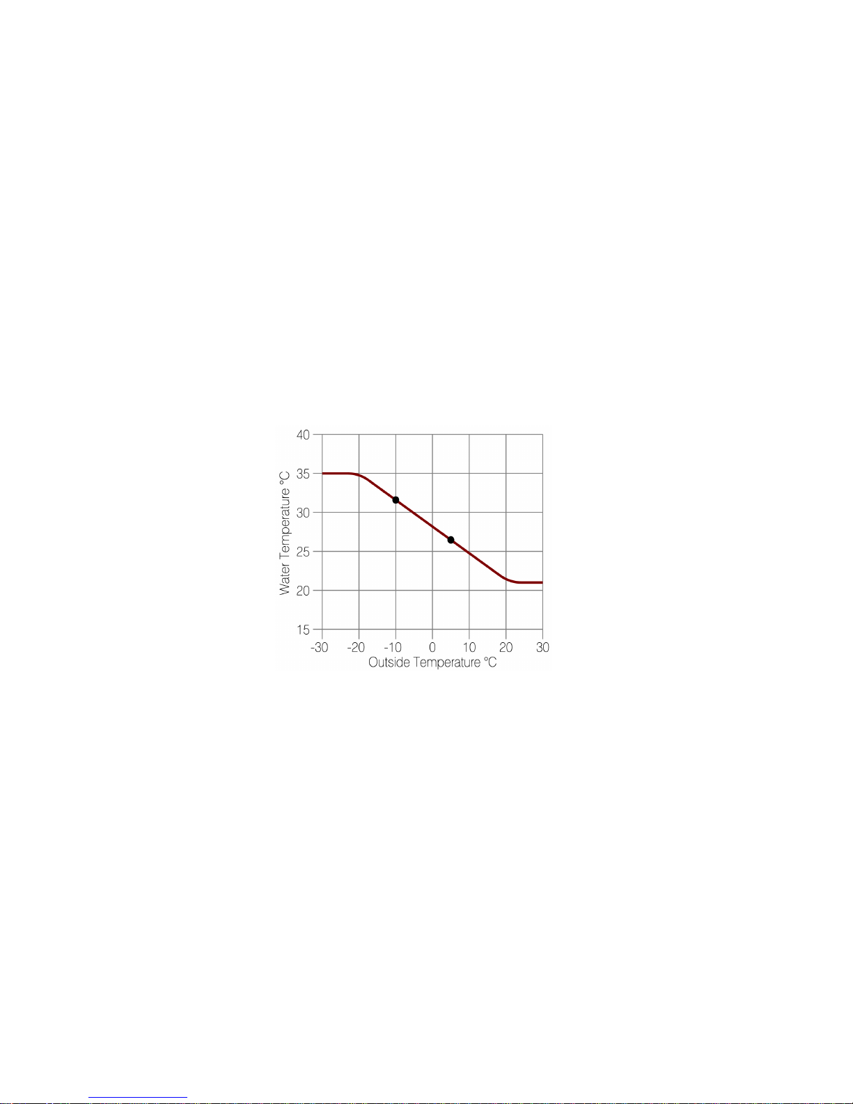
The graph below is an example with the aquastat set to 35º C. During colder weather,
below -20º C, the boiler will maintain the heat output at the aquastat setting, but as
the temperature increases outdoors, the heat output of the boiler will be decreased.
For example when it is -10º C outside the water temperature will be 32º C, and when
it is 5º C outside the water temperature will be 27º C.
Target Water Temperature Example ( Temperature in degrees C)
Dual Thermostat Inputs, two Operating Modes
Dual thermostat inputs allow for two boiler operating modes. These two operating
modes are “normal” and “priority”. The two thermostat inputs allow for one normally
operating thermostat input for “normal” space heating demands, and a second
“priority” thermostat input operating at a higher temperature, for temporary demand
in a zone requiring a higher temperature. Thermostat 1, is for normal space heating,
the water temperature is controlled by the boiler to the setting of the aquastat.
Thermostat 2, the priority thermostat puts the boiler in it's high temperature mode,
the water temperature is controlled by the boiler to a setting of 180°F.
4
Page 5

Specifications
Model kW Volts Phase Amps Minimum Breaker Size Wire Size (Amps)
CEBR2-3 3 240 1 12.5 20 16
CEBR2-5 5 240 1 20.8 30 24
CEBR2-6 6 240 1 25 40 32
CEBR2-8 8 240 1 33.3 50 40
CEBR2-9 9 240 1 37.5 50 40
CEBR2-10 10 240 1 41.7 60 48
CEBR2-12 12 240 1 50 70 56
CEBR2-15 15 240 1 62.5 100 80
CEBR2-18 18 240 1 75 100 80
CEBR2-19 19 240 1 79.2 100 80
CEBR2-20 20 240 1 83.3 125 100
CEBR2-23 23 240 1 95.8 125 100
CEBR2-24 24 240 1 100 125 100
CEBR2-25 25 240 1 104.2 150 120
CEBR2-28 28 240 1 116.7 150 120
CEBR2-208-9 9 208 3 25 40 32
CEBR2-208-11 11.25 208 3 31.2 40 32
CEBR2-208-15 14.7 208 3 40.8 60 48
CEBR2-208-22 22.5 208 3 62.5 100 80
CEBR2-208-30 29.4 208 3 81.6 125 100
CEBR2-600-15 14.7 600 3 14.1 20 16
CEBR2-600-30 29.4 600 3 28.3 40 32
Control Voltage 24 Volts AC
Tank Capacity – Approx. 2 Gallons
Shipping Weight – about 85 pounds
Inlet and Outlet pipe size 1 1/4” NPT
Pump Switch Rating, 120 Volt, 1 HP
Maximum Recommended Operating Temperature 180º F
In Floor heating temperatures are generally 90º F to 110º F
Baseboard and Radiator temperatures are generally 160º F to 180º F
Recommended Operating Pressure 12 PSI
Warning: The control transformer is sized to power only the internal
controls. External devices must be powered from a separate power
source.
5
Page 6

New Boiler Inspection
All Boilers are inspected and tested at the factory prior to shipment. On receipt of your
new boiler, be sure to check for any damage that may have occurred during shipping.
Any such damage should be reported to the carrier immediately.
Never install a damaged boiler.
Unpacking
The Boiler is shipped to you in one carton, which contains the boiler, a pressure &
temperature gauge, pressure relief valve, air vent, outdoor temperature sensor, and
fittings.
System Design
For proper operation of the heating system; the boiler, the radiation system, and
maximum heat loss of the building must be considered. The boiler selected should
provide between 110% and 130% of the maximum design heat loss of the building.
The radiation system should be designed to properly dissipate the heating capacity of
the boiler at the radiation system design temperature.
The recommended cold fill pressure of the system is 12 psi; this pressure should leave
at least 4 psi at the highest point in the heating system. Pressure will decrease at a rate
of 0.433 psi per foot above the fill point. An expansion tank must be included to allow
for approximately 4% expansion of the water in the entire heating system. As the
water in the system is heated the pressure will increase, but a properly sized expansion
tank will prevent the pressure from exceeding the recommended operating pressure.
The radiators or floor system should be designed with parallel loops. If too many
radiators or floor loops are connected in series, the accumulated heat loss may cause
uneven heating. The minimum recommended flow rate must be used, but higher flow
rates may give more even heating. If a number of parallel heating circuits are used,
valves are usually required to balance the flow in each circuit to provide uniform
heating.
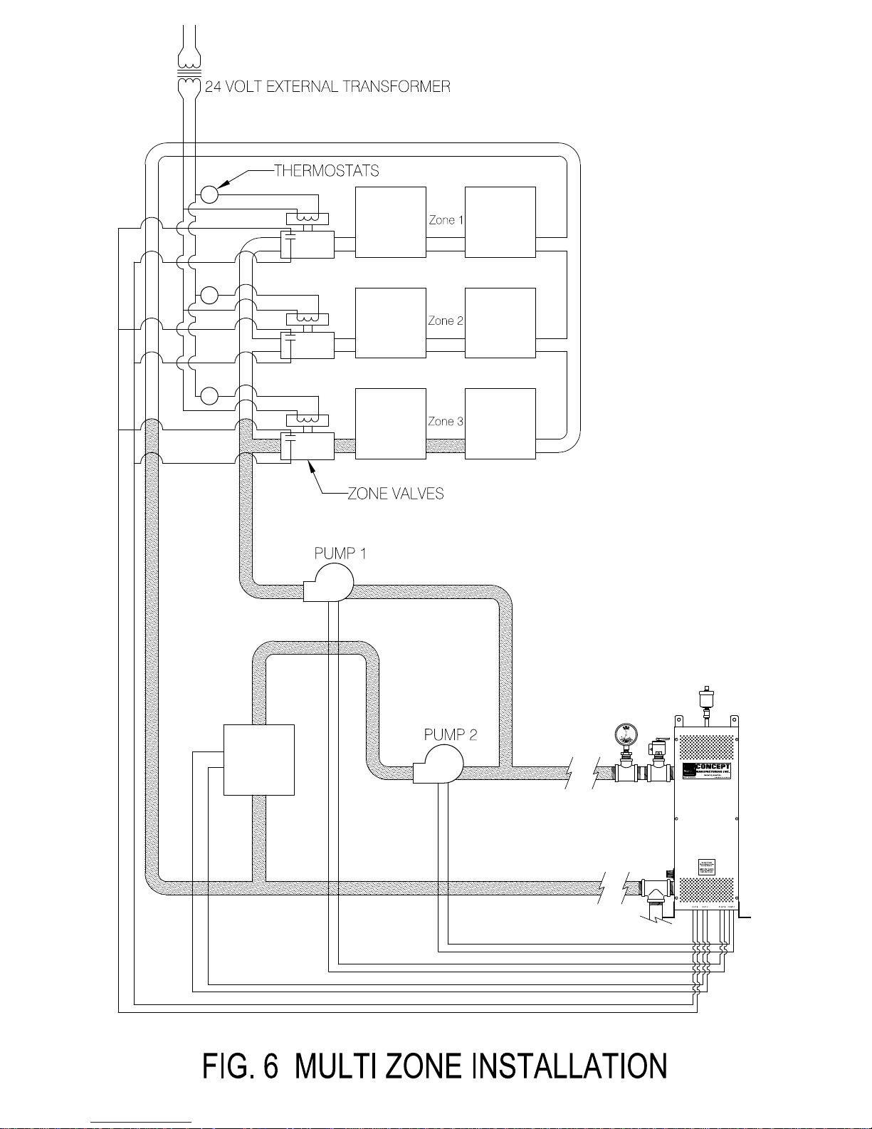
A zoned heating system is also possible with separate heating zones and individual
thermostats in each zone. Individual thermostats in each zone can control a zone valve,
or a circulation pump providing flow to that zone. End switches on the zone valves can
be wired in parallel to the thermostat connection of the boiler.
The entire heating system must comply with all local codes or regulations.
6
Page 7

Installation
Location
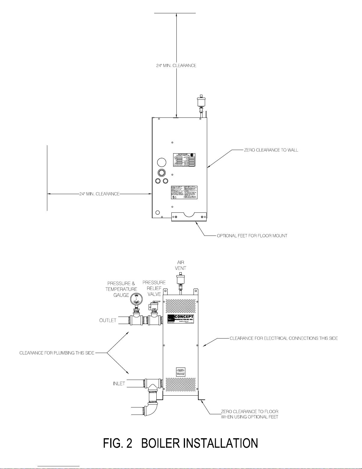
(1)The site selected for installation of your boiler should leave at least 24” of clear
space in front of the unit. The sides require only enough room for plumbing and
electrical connections (see Fig. 2). The rear of the unit is considered as a “Zero
Clearance” face (see Fig. 2). If wall mounting is chosen ensure that the wall can
withstand the weight of the unit including water (approximately 115 lbs.). Two
brackets are provided on top and are drilled for 3/8” bolts or screws, these are
for wall mounting. Optional “Mounting Feet” are available for floor mounting.
Holes are also provided in these feet for floor mounting.
(1)To install the optional feet, the two outside #10 screws at the bottom on each
side are removed. Each of the feet are then lined up with the holes, then the
screws are tightened back in place holding the feet in place.
(2)The space selected should be well ventilated and kept normally below 77º F or
25º C.
(3)Though the unit is suitable for floor or wall mount, only faces indicated as “Zero
Clearance” may be mounted against combustible surfaces.
(4)Units must be mounted straight as shown in Fig. 2 with the outlet at the top,
and the inlet on the bottom. See “Up Arrow” on label on side of boiler.
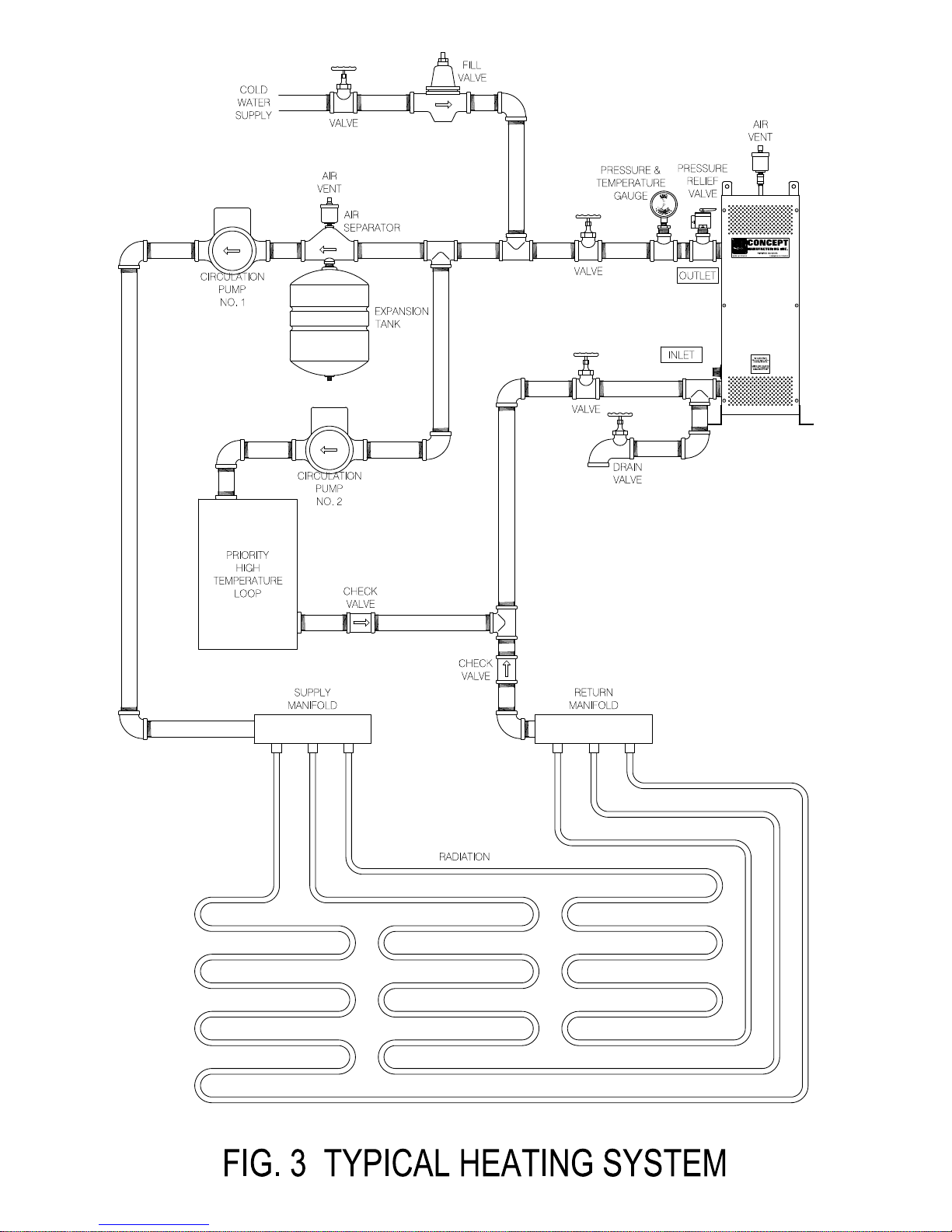
(5)The circulation pumps should be connected to the outlet side of the boiler (see
Fig. 3).
Mechanical Installation
(1)Refer to Fig. 3 for a typical system before installation.
(2)Packed with your boiler are the following.
a) Temperature & Pressure Gauge
b) Pressure Relief Valve
c) Air Vent
d) Outdoor Temperature Sensor
e) Necessary fittings.
(3)Mount unit as per instructions under “Location”
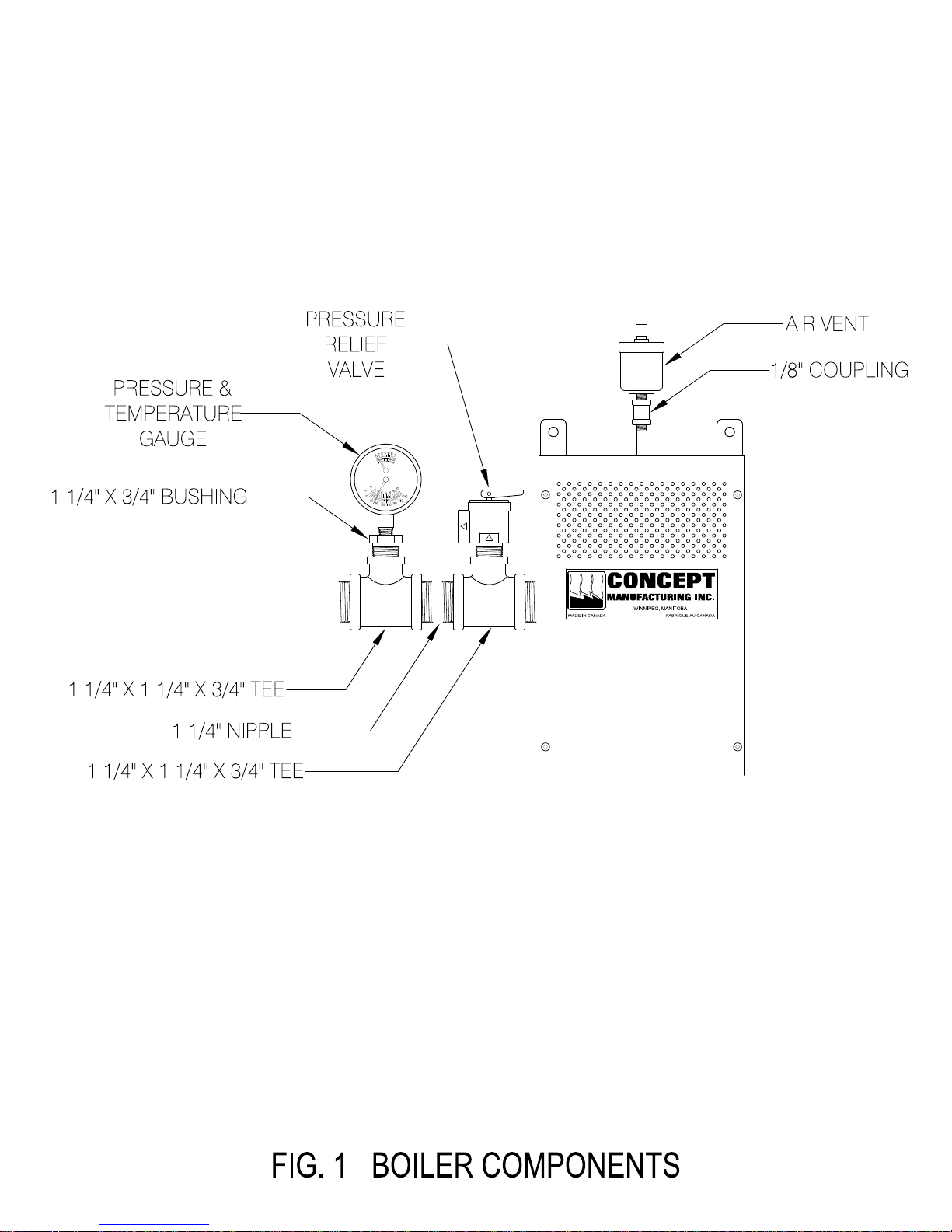
(4)Install Pressure Relief Valve and Pressure & Temperature Gauge. These must be
connected directly to the boiler as shown in Fig. 1
(5) A discharge line must be attached to the outlet of the pressure relief valve. The
discharge line will direct water or steam from the pressure relief valve should it
open. The discharge line must be as short as possible, not have any valves or
restrictions, not be smaller than the outlet of the pressure relief valve, slope
downwards, and the end must be open to the atmosphere. The discharge line
should terminate at a drain 6 inches above the floor level.
(6)Install inlet and outlet piping.
7
Page 8

(7)An expansion tank must be installed (see Fig. 3) to allow for water expansion as
the system is heated.
Dissimilar Metals
Do not connect dissimilar metals on the inlet and outlet nipples. Dielectric Unions
should be used. Another solution is to use brass or cast iron fittings between the boiler
and any copper fittings that you may be using. Failure to do so will result in galvanic
corrosion and cause the inlet and/or outlet nipples to fail over time.
This is not covered under the warranty.
Pump Installation
The circulation pumps should be positioned as close to the boiler as possible, with the
delivery arranged to pump out of the tank outlet on the upper left side of the boiler
(see Fig. 3).
The pumps are powered by the boiler through the terminals P1
located on the 120 volt terminal block (lower right terminal block see Fig. 4 and Fig.
5). The pumps start when the corresponding thermostat terminals on the control
board are closed, and stop when these terminals are opened. Thermostat 1 terminals
“STAT 1” controls pump 1, and thermostat 2 terminals “STAT 2” control pump 2 (the
priority terminals).
L P1N
and P2
L P2N
Thermostat Connections
The thermostat connections are 24 volt AC.
after all other work is complete, and the entire heating system is
thoroughly purged of air.
1” and “STAT 2” on the control circuit board (see Fig. 4 and Fig. 5). STAT 1 is for
normal space heating. STAT 2 is the priority high temperature thermostat. As
STAT 2 is the priority thermostat, it will override STAT 1. When in the priority
high temperature mode, Pump 1 will be switched off even if thermostat 1 is
calling for heat. This prevents the higher temperature water from being circulated
through the normal lower temperature heating zone.
In zoned systems, the end switches of all the zone valves may be connected in parallel
and hooked up to the “STAT 1” connection on the control board. For a typical system
(see Fig. 6).
The thermostats are connected to the terminals “STAT
Only connect the thermostats
Thermostats described as “Power Stealing” or as “Parasitic
Thermostats” must not be used.
8
Page 9

Thermostat Anticipators
The thermostat anticipator setting recommended is 0.2 amps. Failure to correctly
adjust this setting may result in unsatisfactory comfort conditions, and could result in
damage to the thermostat.
This setting may have to be adjusted slightly to ideally match the boiler control system
to the thermostat, as well as overcome the normal inertia of the radiation system. A
setting to low will be characterized by a short cycle, which does not allow the room
temperature to be satisfied before the boiler shuts down. A setting too high will be
characterized by a long cycle, which allows the room temperature to rise too high
before the boiler shuts down. Adjustments should be made to the setting, if required,
but should not exceed 0.1 amps per adjustment.
Newer electronic thermostats typically have provisions for the cycle length, and type of
heating system. The instructions for the thermostat should be followed.
In zoned systems where the thermostat is controlling a zone valve, or circulation pump
and not the boiler, the anticipator should be set to match the current draw of the zone
valve being used.
Temperature Control Setting (Aquastat)
The boiler has a temperature control knob known as an aquastat on the left hand side.
This sets the maximum temperature that the boiler will operate at while in the normal
mode. The internal control system monitors the water temperature in the tank and
modulates the heating elements to maintain the desired water temperature. Note that
the setting on the knob only sets the maximum temperature, it is normal for the boiler
to operate at lower temperatures than this setting at times, this is especially true in the
spring and fall when it is not so cold outside. The actual temperature setting will be
determined by the type of heating system the boiler is installed in. While in priority
mode the aquastat setting is overridden as the boiler goes to it's high temperature
operation, the water temperature is controlled to 180°F .
Outdoor Temperature Sensor Connection
The outdoor temperature sensor should be mounted in a suitable location outside the
building where it will be exposed to the outside air. Mount the sensor high enough so
it will not be covered by snow or ice, and in a location where it will not be exposed to
direct sunlight.
The outdoor temperature sensor is connected to the terminals “OD STAT” on the
control circuit board (see Fig. 4 and Fig. 5).
9
Page 10

Start Up
A new system must be thoroughly cleaned, flushed and drained, then refilled with
clean water. Foreign material circulating through the system could be detrimental to
the pump and to the heat transfer efficiency of the system and may lead to future
problems. The system must be thoroughly purged of air before it is energized for
the first time. Elements will burn out if the boiler is not full of water when the
boiler is turned on. Do not connect the thermostat wires until the entire system
is full of water, and thoroughly purged of air.
The automatic air vent is to assist in removing air from the top of the tank to prevent
elements from burning out. It alone is not sufficient in removing air from the entire
heating system. Additional air vents must be installed throughout the system to
eliminate any air that may enter the system.
Check List
(1)Plumbing complete.
(2)System flushed.
(3)System free of air (purged).
(4)Pumps rotates freely.
(5)Thermostats connected.
(6)Thermostat anticipators set.
(7)Outdoor Sensor connected.
(8)Electrical supply connections complete.
Maintenance
At the start of each heating season it is advisable to have a qualified technician check
and inspect the boiler and the heating system for proper operation.
10
Page 11

Troubleshooting Guide
Problem Correction
Boiler not heating, water cool. Check power supply, fuses or breakers.
Check thermostat setting.
Check temperature control on side of boiler.
Boiler heating pipes cool. Check for air in system.
Check pump circulation.
Check all valves.
Check for flow stoppage, or air locks.
Boiler rapid cycles. Check anticipator setting.
Check pump circulation.
Boiler operates continuously. Check anticipator setting.
Boiler noisy. Oversized pump.
Flow rate too high.
Flow rate too low.
Pump location incorrect.
Boiler not heating enough Insufficient capacity.
Burnt Elements.
Flow rate too low.
Pressure too high. Defective expansion tank.
Defective automatic fill valve.
Expansion tank too small.
Safety relief valve dripping. Check expansion tank.
Flush relief valve.
See the troubleshooting step by step procedure at the end of this manual for additional
information.
11
Page 12

Concept Manufacturing Inc. Limited Warranty
Concept Manufacturing Inc. (the "Manufacturer") warrants its Hydronic Boiler (the
"Boiler") to be free from defects in material and workmanship under normal use and
maintenance for a period of two (2) years from the date of original installation. The
Manufacturer further warrants the tank to be free from defects in material and
workmanship under normal use and maintenance for an additional eight (8) years for a
total of ten (10) years from the date of original installation.
If any part of the Boiler is found by the Manufacturer, as sole judge, to be defective in
material or workmanship, the Manufacturer, at its sole discretion, agrees to:
(i) Repair any defect;
(ii) replace any defective Boiler; or
(iii) refund the original purchase price of the Boiler.
The Manufacturer, at its sole discretion, reserves the right, at any time during the
warranty period, to refund the original purchase price to the current owner of the
Boiler regardless of any prior attempt by the Manufacturer to repair or replace that
Boiler.
The obligation of the Manufacturer to repair, replace or refund the purchase price
exists provided the defective part or complete unit is returned to the Manufacturer.
ANY AND ALL TRANSPORTATION COSTS WILL BE BORNE BY THE
PURCHASER.
Repair, replacement or refund of any defective part or unit shall be considered as
complete fulfillment of this warranty.
THIS WARRANTY DOES NOT APPLY TO:
1. Labor or other costs incurred for diagnosing, repairing, removing, installing,
reinstalling, shipping, servicing or handling of any defective part or complete unit;
2. Costs incurred for normal maintenance;
3. The workmanship of any installer of the Boiler. In addition, this warranty does not
assume any liability of any nature for unsatisfactory performance caused by improper
installation;
4. Damage or repair as a consequence of storage and handling, improper or careless
installation, improper maintenance, or misuse or neglect as determined by the
Manufacturer as sole judge;
12
Page 13

5. Damage as a consequence of misapplication, abuse, improper servicing,
unauthorized alteration, improper operation or usage contrary to the Manufacturer's
direction, design or specifications, as to any and all of which the Manufacturer shall be
the sole judge;
6. Damage as a consequence of electrical surges, inadequacy or interruption of
electrical services or corrosion, whether caused by chemicals or the environment;
7. Damages as a consequence of floods, winds, fires, lightning, freezing conditions or
other conditions beyond the control of the Manufacturer.
LIMITATION OF WARRANTY
THIS LIMITED WARRANTY IS IN LIEU OF ALL OTHER WARRANTIES WHETHER
EXPRESS OR IMPLIED, AND ALL SUCH OTHER WARRANTIES, INCLUDING
WITHOUT LIMITATION IMPLIED WARRANTIES OF MERCHANTABILITY OR
FITNESS FOR A PARTICULAR PURPOSE, ARE HEREBY DISCLAIMED AND
EXCLUDED FROM THIS LIMITED WARRANTY.
THE MANUFACTURER'S LIABILITY ON ANY CLAIM OF ANY KIND, INCLUDING
NEGLIGENCE, WITH RESPECT TO THE GOODS OR SERVICES COVERED
HEREUNDER, SHALL IN NO WAY EXCEED THE PURCHASE PRICE OF THE
BOILER, OR PART THEREOF, WHICH GIVES RISE TO THE CLAIM. IN NO EVENT
SHALL THE MANUFACTURER BE LIABLE FOR SPECIAL, INCIDENTAL,
INDIRECT, OR CONSEQUENTIAL DAMAGES, OR ANY DAMAGES IN THE
NATURE OF PENALTIES. ALL WORK UNDER THE TERMS OF THIS WARRANTY
SHALL BE PERFORMED DURING NORMAL WORKING HOURS.
ALL REPLACEMENT PARTS OR UNITS, WHETHER NEW OR
REMANUFACTURED, ASSUME AS THEIR WARRANTY PERIOD ONLY THE
REMAINING TIME PERIOD OF THIS WARRANTY.
13
Page 14
14
Page 15
15
Page 16
16
Page 17
17
Page 18
18
Page 19
19
Page 20

Troubleshooting Step By Step Procedure
The following is a step by step procedure to help in troubleshooting any problems with
this boiler. These steps should be preformed only by qualified personnel with
experience in hydronic heating systems, and electrical heating equipment. You are
working with high voltages and should be extremely careful.
Before energizing boiler, ensure system is full of water.
(1)Make sure that there is power to the boiler. There must be power to the boiler
to complete these troubleshooting steps.
a) On 240 volt single phase models there should be power at the main terminal
block. You should read 120 volts between L1 and N, 120 volts between L2
and N, and 240 volts between L1 and L2.
b) On three phase models there should be power at the main terminal block.
You should take three readings on the main terminal block, you should read
the appropriate voltage for your model between L1 and L2, between L2 and
L3, and between L1 and L3. You should also read 120 volts on the terminal
block on the lower right side on the terminals labeled SL and SN.
c) Disconnect the thermostat wires from the terminals “STAT 1” AND “STAT
2”. Measure the voltage at the top of the boiler at each heating element. If
you measure voltage at any of the elements, then the element relay for that
element is stuck on and needs to be replaced.
(2)Check the fuse on models equipped with a fuse.
a) Remove the fuse located inside the boiler. Check it for continuity. Replace
with a new fuse of the correct type if necessary.
b) Otherwise replace the existing fuse.
(3)Check that there is 24 volt AC power on the secondary side of the transformer.
These are the two wires running from the transformer to the control board.
There must be 24 volt AC power on the secondary side of the transformer for
the boiler to operate. If there is no power the transformer needs to be replaced.
(4)With the thermostat wires still disconnected from step (1)c), disconnect the
outdoor sensor as well, then connect a jumper wire from one terminal of STAT 1
to the other terminal of STAT 1.
a) This should energize the left hand Pump Relay to the right of the control
board, you should hear a click. If not check that there is 24 volt AC power on
the two terminals with purple wires going to this relay.
b) Remove the jumper wire from the “STAT 1” terminals, and jumper the
“STAT 2” terminals. This should energize the right hand Pump Relay. If not
check that there is 24 volt AC power on the two terminals with purple wires
going to this relay.
c) If there is no power at the relay, the control board needs to be replaced.
d) If there is power, but one of the relays is not turning on, replace that relay.
20
Page 21

(5)When the relay is energized, it will supply 120 volt power for running the pump,
and activate the control board.
a) There should now be 120 volt AC power to the terminals labeled P2L and
P2N, as “STAT 2” has the jumper wire connected.
b) If there is no power, replace the relay.
c) Reconnect the jumper to the “STAT 1” terminals, there should now be 120
volt AC power to the terminals labeled P1L and P1N, as “STAT 1” has the
jumper wire connected.
(6)With the circuit board now activated, the power relays should turn on one at a
time. There is about a one to two minute delay before the first relay turns on,
and about the same for each additional relay. If they have not started to come on
as yet, temporarily turn up the temperature on the aquastat to the maximum
setting, it should be returned to the normal setting when you are finished
troubleshooting. The power relays for controlling the elements should now start
to turn on. It may take a minute or two for the first relay to turn on, and about
the same length of time for each subsequent relay to turn on. As each relay
turns on, one indicator light on the control board should come on as well.
a) If the element relay indicator lights do not come on, disconnect the
temperature sensor by pulling out the connector at the control board (the
one with the two gray wires).
b) If the indicator lights now come on, after waiting for the one to two minute
delay between each element the temperature sensor needs to be replaced. If
the indicator lights still do not come on the control board needs to be
replaced.
c) If the indicator lights come on, but the relays for the elements do not come
on then the low water cut off or the high limit control may be preventing
them from coming on. This may be due to a faulty component, or may be an
actual low water, or high temperature condition.
(7)If the boiler is equipped with the low water cut off option try the following only
when you are sure the boiler and the heating system are completely full of
water.
a) Unplug the low water cut off from the control board. Temporarily (no more
than one second) place a jumper wire across the two pins of the low water
cut off connector on the control board, the element relays should all
immediately turn on.
b) If the relays energize, replace the low water cut off, otherwise go on to the
next step.
(8)Temporarily (no more than one second) place a jumper wire across the two
terminals on the high limit control.
a) If the relays energize, replace the high limit control.
(9)If all the relays energize and there is no heat, then check for power to each of
the heating elements.
a) With all the relays energized, check that there is power to each of the
elements with a volt meter. If there is no voltage reading, replace the relay
21
Page 22

connected to that element.
b) If there is power to the elements, but no heat, then with the all the power
disconnected to the boiler, check the resistance of each element with an ohm
meter, and replace any elements, as necessary.
If you have gone through the above steps, and the boiler is still not working, please
contact us for assistance.
Concept Manufacturing Inc.
Box 23008 RPO McGillivray
Winnipeg, Manitoba, Canada
R3T 5S3
Phone: 204-284-9111
Fax: 204-284-9229
Toll Free: 800-465-4114
E-mail [email protected]
22
 Loading...