

Linz electric E1S10M I, E1S10L L, E1S11M A, E1S10M H, E1S11M AS Operation And Maintenance
...
IT Istruzioni per l’uso e manutenzione
ALTERNATORI
Istruzioni originali
EN Operation and maintenance
ALTERNATORS
With translation of the original instructions
ES Instrucciones para el uso y mantenimiento
ALTERNADORES
Con la traducción de istrucciones originales
FR Mode d’emploi et d’entretien
ALTERNATEURS
Avec la traduction de instructions d’origine
DE Gebrauchs und wartungsanleitung
GENERATOREN
Mit Übersetzung der ursprünglichen Anweisungen
English
E1S
Español ItalianoFrançaisDeutsch
LA INSTALACIÓN DEBE SER REALIZADA SÓLO POR
PERSONAL AUTORIZADO POR LINZ ELECTRIC SPA
THE INSTALLATION MUST BE PERFORMED ONLY BY
PERSONNEL AUTHORIZED BY LINZ ELECTRIC SPA
L’INSTALLAZIONE DEVE ESSERE EFFETTUATA SOLO DA
PERSONALE AUTORIZZATO DALLA LINZ ELECTRIC SPA
L’INSTALLATION DOIT ÊTRE EFFECTUÉE UNIQUEMENT PAR
DU PERSONNEL AUTORISÉ PAR LINZ ELECTRIC SPA
DIE INSTALLATION DARF NUR DURCH AUTORISIERTES PERSONAL
ERFOLGEN VON LINZ ELECTRIC SPA

- 2 -
Arcole (Vr): Data del documento di consegna
Date of the delivery document
Fecha del documento de entrega
Date du document de livraison
Datum des Lieferdokuments
LINZ ELECTRIC Spa
Giulio Pedrollo
Rappresentante legale - custode e detentore del Fascicolo Tecnico
Legal representative - Keeper and holder of the Technical Dossier
Representante legal - Receptor y poseedor del Expediente Técnico
Représentant légal - Responsable et détenteur du Dossier Technique
Rechtlicher Verteter - Aufbewahrer und Inhaber der technischen Akte
DECLARATION OF CONFORMITY
AND INCORPORATION
The manufacturer LINZ ELECTRIC Spa - Viale
del Lavoro, 30 - 37040 Arcole (VR) Italy,
declares that the components described in this
manual are manufactured in compliance with
standards: EN 60034-1, EN 60204-1, EN
61000-6-2, EN 61000-6-4, EN 55014-1, EN
55011.
They are therefore in conformity with the Directives:
- 2006/42/EC (Machiner y Directive);
- 2014/35/UE (Low Voltage);
- 2014/30/UE (Electromagnetic Compatibil-
ity).
Such conformity, the use of these ranges of
components in machines that apply the Directive 2006/42/EC, provided that their integration
or their incorporation and/or assembly conforms to, among other things, the rules of EN
60204 «Electrical equipment of Machines» and
our installation instructions.
The components dened above can not be put
into service until the machinery into which they
are incorporated has been declared in conformity with the applicable directives.
Note: When the components are fed with
specially adapted electronic converters and/or
subservient to electronic monitoring and control systems must be installed by a professional
who assumes responsibility for compliance with
the rules on electromagnetic compatibility
regulations of the country in which it is installed
machine.
DÉCLARATION DE CONFORMITÉ
ET CONSTITUTION
Le fabricant LINZ ELECTRIC Spa - Viale del
Lavoro, 30 - 37040 Arcole ( VR) Italie,
déclare que les éléments décrits dans ce manuel
sont fabriqués en conformité avec les normes:
EN 60034-1, EN 60204-1, EN 61000-6-2, EN
61000-6-4, EN 55014-1, EN 55011.
Ils sont donc en conformité avec les directives :
- 2006/42/CE (Directive machines);
- 2014/35/UE (Basse tension);
- 2014/30/UE (Compatibilité Electromagné-
tique).
Cette conformité, l’utilisation de ces gammes de
composants dans les machines qui appliquent
la directive 2006/42/CE, à condition que leur
intégration ou leur incorporation et/ou le
montage est conforme, entre autres choses, les
règles de eN 60204 «Equipement électrique des
machines» et nos instructions d’installation.
Les composants dénis ci-dessus ne peuvent
pas être mis en service avant que la machine
dans laquelle ils sont incorporés a été déclarée
conforme aux directives applicables.
Remarque: Lorsque les composants sont alimentés par des convertisseurs électroniques
adaptés et/ou asservis à des systèmes de surveillance et de contrôle électronique doit être
installé par un professionnel qui assume la responsabilité de la conformité avec les règles sur
les règles de la compatibilité électromagnétique
du pays dans lequel il est installé machine.
DECLARACIÓN DE CONFORMIDAD
E INCORPORACIÓN
El fabricante LINZ ELECTRIC Spa - Viale del
Lavoro, 30 - 37040 Arcole (VR) Italia, declara
que los componentes descritos en este manual
son fabricados de conformidad con las normas:
EN 60034-1, EN 60204-1, EN 61000-6-2, EN
61000-6-4, EN 55014-1, EN 55011.
Son, por tanto, de conformidad con las Directivas:
- 2006/42/CE (Directiva máquinas);
- 2014/35/UE (Baja Tensión);
- 2014/30/UE (Compatibilidad Electromag-
nética).
Tal conformidad, el uso de estas gamas de componentes en máquinas que aplican la Directiva
2006/42/CE, a condición de que su integración o
su incorporación y/o montaje se ajusta a, entre
otras cosas, las normas de EN 60204 «Equipo
Eléctrico de las Máquinas» y las instrucciones
de instalación.
Los componentes denidos anteriormente no
pueden ser puestos en servicio hasta que la
maquinaria en la que están incorporados haya
sido declarada en conformidad con las directivas
aplicables.
Nota: Cuando los componentes son alimentados con convertidores electrónicos adaptados
y/o amoldarse a los sistemas de supervisión y
control electrónico debe ser instalado por un
profesional que asume la responsabilidad por el
cumplimiento de las normas relativas a la normativa de compatibilidad electromagnética del
país en el que está instalado máquina.
KONFORMITÄTSERKLÄRUNG
UND EINGLIEDERUNG
Der Hersteller LINZ ELECTRIC Spa - Viale del
Lavoro , 30 - 37040 Arcole (VR) Italien, er-
klärt, dass die in diesem Handbuch beschriebenen Komponenten werden in Übereinstimmung
mit den Normen: EN 60034-1, EN 60204-1,
EN 61000-6-2, EN 61000-6-4, EN 55014-1,
EN 55011. Sie sind daher in Übereinstimmung
mit den Richtlinien:
- 2006/42/EG (Maschinenrichtlinie);
- 2014/35/UE (Niederspannung);
- 2014/30/UE (Elektromagnetische Verträg-
lichkeit).
Solche Konformität, die Verwendung dieser
Bereiche von Komponenten in Maschinen, die
in der Richtlinie 2006/42/EG gelten, vorausgesetzt, dass ihre Integration oder deren Einbau
und/oder Montage entspricht, unter anderem
den Regeln der EN 60204 «Elektrische Ausrüstung von Maschinen» und unsere Installationsanweisungen. Die oben denierten Komponenten nicht in Betrieb genommen werden, bis die
Maschine, in die sie eingebaut werden, ist in
Übereinstimmung mit den geltenden Richtlinien erklärt werden.
Hinweis: Wenn die Komponenten mit speziell
angepassten elektronischen Konvertern und/
oder unterwürg elektronische Überwachungsund Kontrollsysteme eingespeist muss von
einem Fachmann, der die Verantwortung für die
Einhaltung der Vorschriften zur elektromagnetischen Verträglichkeit Vorschriften des Landes
geht davon aus , in dem es installiert ist, installiert werden Maschine.
DICHIARAZIONE DI CONFORMITÀ
E DI INCORPORAZIONE
Il costruttore LINZ ELECTRIC Spa - Viale del
Lavoro, 30 - 37040 Arcole (Vr) Italia, dichia-
ra che i componenti descritti in questo manuale,
sono costruiti in osservanza alle norme: EN
60034-1, EN 60204-1, EN 61000-6-2, EN
61000-6-4, EN 55014-1, EN 55011.
Sono quindi conformi alle Direttive:
- 2006/42/CE (Direttiva Macchine);
- 2014/35/UE (Bassa Tensione);
- 2014/30/UE (Compatibilità Elettromagneti-
ca).
Queste conformità consentono l’uso di queste
gamme di componenti in macchine che applicano la Direttiva Macchine 2006/42/CE, con
riserva che la loro integrazione o la loro incorporazione e/o assemblaggio siano eettuati conformemente, tra l’altro, alle regole della norma
EN 60204 «Apparecchiatura Elettrica delle Macchine» e alle nostre istruzioni d’installazione.
I componenti sopra deniti non potranno essere
messi in servizio prima che la macchina in cui
sono incorporati sia stata dichiarata conforme
alle direttive applicabili.
Nota: Quando i componenti sono alimentati
con convertitori elettronici adattati e/o asserviti
a dispositivi elettronici di controllo e di comando, devono essere installati da un professionista
che si assuma la responsabilità del rispetto
delle regole sulla compatibilità elettromagnetica vigenti nel Paese in cui viene installata la
macchina.
ITALIANO ENGLISH
ESPAÑOL FRANÇAIS
DEUTSCH

- 3 -
1
A B
Mod. L (mm)
E1S10 2
E1S11 2
E1S13 4
2
A B
3
A B
4
A B
5
A B
6
A B
7
A B

- 4 -
12
8
9
10 11
A
B
A
B

- 5 -
1. MISURE DI SICUREZZA
Prima di utilizzare il gruppo elettrogeno è indispensabile leggere il manuale “Uso e manutenzione” del
gruppo elettrogeno e dell’alternatore e seguire le raccomandazioni seguenti.
⇒
Un funzionamento sicuro ed eciente può essere raggiunto solo se le macchine vengono utilizzate
in modo c orretto, se condo quant o previsto d ai relativi m anuali di “Us o e manutenzi one” e dalle
norme di sicurezza.
⇒ Una sca rica elet trica può c ausare grav i danni e addi rittura l a morte.
⇒ È vieta to toglie re la calo tta di ch iusura de lla scat ola mors etti e le g riglie di p rotezi one dell ’alternato re
nché l o stesso è in mov imento e prim a di avere disa ttivato il si stema di avv iamento del g ruppo elettrogeno.
⇒ La manutenzione del gruppo deve essere eettuata esclusivamente da personale qualicato e specia-
lizzato.
⇒ Non operare con indumenti “sciolti” in vicinanza del gruppo elettrogeno.
⇒
Le persone addette alla movimentazione devono sempre indossare guanti da lavoro e scarpe antinfortunistiche. Q ualora il generatore o l’intero gruppo debba ess ere sollevato da terra, gli operai devono
usare u n casco pro tettivo.
L’installatore nale del gruppo elettrogeno è responsabile della predisposizione di tutte le misure
necess arie a rende re l’inter o impianto con forme alle vi genti norme l ocali di sic urezza (mess a a terra,
protezioni contro il contatto, protezioni contro le esplosioni e l’incendio, arresto di emergenza, ecc…).
Messa ggi di sicurez za: Nel pres ente manuale us eremo dei simbo li che hanno il se guente signi cato:
IMPORTANTE! Si riferisce ad una operazione rischios a o pericolosa che può causare danni al prodotto.
CAUTELA! Si riferisce ad una operazione rischiosa o pericolosa che può danneggiare il prodotto e può causa-
re ferite alle persone.
ATTENZIONE! Si rifer isce ad una ope razione ris chiosa o peri colosa che pu ò causare gr avi ferite o pos sibile morte.
PERICOLO! Si rifer isce ad un ris chio immed iato che potr ebbe caus are gravi fe rite o la mort e.
2. DESCRIZIONE DELL’ALTERNATORE
Gli alter natori della s erie E1S sono trifa se a due e quattr o poli, con spaz zole e con avvol gimento ausil iario (carica to su un
Compound) che assicura la regolazione della tensione.
Essi so no costr uiti in con formit à a quanto pre visto dal le norme
EN 60034-1, EN 60204 -1, EN 55014-1, EN 55011, EN610006-2, EN 61000-6-4 ed alle dirett ive 2006/95/CE, 20 04/108/CE, e 200 6/42/CE.
Ventilazione.
Assiale con aspirazione dal lato oppos to accoppiamento.
Protezione. Standar d IP 21. A richiesta I P 23.
Senso di rotazione. Sono ammessi ambedue i sensi di rotazione.
Caratteristiche elettriche. Gli is olamenti son o realizzat i con materiale d i classe H sia nel lo statore ch e nel rotore.
Gli avvolgimenti sono tropicalizzati.
Potenze. Sono riferite alle seguenti condizioni: temperatura ambiente non superiore a 40°C, altitudine non superiore a
1000 m. s.l .m., serviz io continuo a
Cosф
= 0.8.
Sovraccarichi
Si accet ta generalme nte un sovracc arico del 10% pe r 1 ora ogni 6 ore.
C
aratteristiche meccaniche.
La cass a e gli scudi son o in lega di allum inio resiste nte alle vibra zioni. L’albero è in accia io ad alta resis tenza.
Il rotore è particolarmente robusto per resistere alla velocità di fuga dei motori di trascinamento ed è dotato di una
gabbia di smorzamento che permette un buon funzionamento anche con carichi monofase distorcenti. I cuscinetti
sono lub ricati a vit a.
Funzionamenti in ambienti particolari.
Nel caso l’alternatore debba funzionare ad una altitudine superiore ai 1000 m s.l.m. è necessario attuare una riduzione
della pot enza erogata de l 4% ogni 500 metri di i ncremento. Quan do la temperatur a dell’ambiente è sup eriore a 40° C si
deve ridu rre la potenz a erogata dall ’alternatore d el 4% ogni 5°C di inc remento.
MESSA IN SERVIZIO
Le seguenti operazioni di controllo e di messa in servizio devono essere eseguite solo da personale qualicato.
⇒ L’alte rnatore dov rà essere i nstallat o in un locale c on possibi lità di sca mbio dell’ar ia con l’atmos fera per imp edire che
la temper atura ambien te superi i valo ri previst i dalle norme.
⇒ Bisogna fare a ttenzion e che le aper ture previ ste per l’aspi razione e lo s carico del l’aria non siano m ai ostrui te e che la
tecnic a prescelta p er il piazzam ento dell’alter natore sia tale d a evitare l’aspi razione dir etta dell’ari a calda in usci ta
dall’alte rnatore stes so e/o dal motore p rimo.
⇒ Prima della mes sa in funzi one è necess ario contr ollare visi vamente e man ualmente ch e tutti i mor setti d elle divers e
morsettiere siano serrati regolarmente e che non esista impedimento alcuno alla rotazione del rotore. Nel caso l’alternato re sia stato i nutilizz ato per lung o tempo, prima d i metterl o in serviz io controll are la resis tenza di iso lamento
verso ma ssa degl i avvolgi menti tene ndo pres ente che og ni singola p arte da co ntrollar e deve esse re isolat a dalle alt re.
Questo c ontroll o si dovrà es eguire co n lo strume nto a 500 V. c.c. de nominato Me gger. Norma lmente ven gono riten uti
sucie ntemente iso lati gli avvol gimenti che h anno un valore d i resistenz a verso mass a ≥ 1 MΩ. Nel caso c he il dato
rilevato sia inferiore è necessario procedere ad un ripristino dell’isolamento asciugando l’avvolgimento utilizzando
per es. un f orno a 60 - 80°C (o fac endo circolare n ello stesso un ad atto valore di co rrente elet trica ottenu ta da una
sorgen te ausiliar ia). È necessa rio veri care che le p arti me tallich e dell’alter natore e la ma ssa dell’ intero gr uppo siano
collegati al circuito di terra e che quest ’ultimo risponda alle prescrizioni di legge.
Error i o dimentic anze nella me ssa a terra po ssono caus are conse guenze anch e mortali.
3. ISTRUZIONI PE R IL MONTAGGIO
Il montaggio deve essere eet tuato da persone qualicate dopo la lettura del manuale.
Forma costruttiva B3/B14
La form a costrut tiva B3/B14 obbliga a ll’uso di un giunt o elastico tr a motore primo e a lternatore.
Il giunto e lastico n on dovrà da re origin e a forze as siali o radi ali durant e il funzio namento e do vrà esse re montat o rigidame nte
sulla sporgenza dell’albero dell ’alternatore. Si consiglia di eseguire l’assemblaggio seguendo le seguenti fasi:
1) Applic are sull’alter natore il se migiunto e la c ampana di alli neamento co me rappres entato nella gura 1A.
Nel posizionamento del semigiunto sull’alternatore tenere presente che il rotore, ad accoppiamento completato,
deve pote r conservare la p ossibilità di d ilatarsi assia lmente verso il c uscinetto la to opposto accop piamento; perch é
ciò sia possibile è necessario che a montaggio nito la sporgenza dell’albero sia posizionata rispetto alle lavorazioni
del cope rchio, come rap presentato n ella gura 1B e relativa tabella.
2) Applicare su lla parte rot ante del motor e diesel il rela tivo semi-g iunto come ind icato in gura 2A.
3) Montare i tasselli elastici del giunto.
4) Accoppiar e l’alternator e al motore pri mo ssando co n le apposite v iti la campan a di accoppiame nto (vedi gura 2B).
5) Fissare con adatti antivibranti l’insieme motore-alternatore alla base facendo attenzione che non si creino tensioni
Italiano
ITALIANO
- 6 -
tendenti a deformare il naturale allineamento delle due macchine.
6) Osser vare che il cuscinetto lato opposto accoppiamento dell’alternatore abbia il previsto spazio di dilatazione (minimo
2 mm) e sia prec aricato dall a molla di prec arico.
Forma costruttiva B3/B9
Tale forma costruttiva prevede l’accoppiamento diretto tra motore primo e alternatore. Si consiglia di procedere all’assemblaggio nel seguente modo:
1) Fis sare il coper chio «C» al mot ore primo come r appresent ato nella gura 3A.
2) Appli care il tir ante (13) per il ssag gio assial e del rotor e avvita ndolo a fon do sulla spo rgenza de ll’albero d el motore co me
rappresentato nella gura 3B.
3) Fis sare l’altern atore al suo cope rchio con i 4 bull oni previsti c ome indicato n ella gura 4A.
4) Blocc are assia lmente il r otore app licand o la rondel la (50) e serr ando il dad o autoblo ccante (51) con c hiave dinam ometr ica
(coppia di s erraggio 35 Nm pe r tiranti M8; 55 Nm pe r tiranti M10 e 100 Nm per i t iranti M14) (gura 4B).
Pr ima di appli care il dado o sservar e che la porz ione let tata del tir ante entri ne l rotore per mettend o
così un si curo bloc caggio. Ino ltre prim a del montag gio veric are che le se di coniche d i accoppia mento
(su alternatore e motore) siano regolari e ben pulite.
Forma B2
Anche tale forma prevede l’accoppiamento diretto tra motore e alternatore. Si consiglia di pro cedere all’assiemaggio nel
seguente modo:
1) Con trollare il cor retto pos izionamento d el rotore con l’au silio della tab ellina ripor tata in gura 5A.
2) Togli ere eventuali m ezzi di blocc aggio del rot ore posti sul l ato opposto ac coppiamento.
3) Av vicinare l’alte rnatore al mot ore primo come r appresent ato in gura 5B.
4) C entrare e ss are lo stato re alla angia de l motore prim o con le apposi te viti come ind icato in gura 6A.
5) Centr are e ssare con le a pposite viti il gi unto del rotore al v olano del motore p rimo, agendo att raverso le aper ture
apposi te, come indica to in gura 6B.
Girar e il rotore c ome indic ato in gur a 7A e 7B.
CONTROLLI FINALI
Al termine di tutti gli accoppiamenti sopradescritti è necessario controllare il corretto posizionamento
assiale; si deve cioè vericare che:
1)
tra la ne del cuscinetto L.O.A. e la parete di bloccaggio assiale esista uno spazio di dilatazione di:
2 mm per g li alternator i E1S10
3 mm per g li alternator i E1S11 ed E1S13
2) che le spa zzole siano ce ntrate sugli an elli del colle ttore.
4. UTILIZZAZIONE
Le operazioni di collegamento dei cavi di potenza devono essere eseguite da personale qualicato con
macchina denitivamente ferma e scollegata elet tricamente dal car ico.
Tensione e frequenza di erogazione: questi alternatori sono predisposti per erogare esclusivamente la tensione e la
frequenza riportate in targhetta.
5. SCHEMA ELE TTRICO (Figura 8)
Collegamenti dei cavi di potenza
Gli alternatori E1S possono funzionare sia con collegamento a stella con neutro che a triangolo. La
morsettiera principale dovrà essere quindi collegata (a seconda dei casi) come in figura 9: A =
Collegamento Stella/Neutro; B = Collegamento Triangolo.
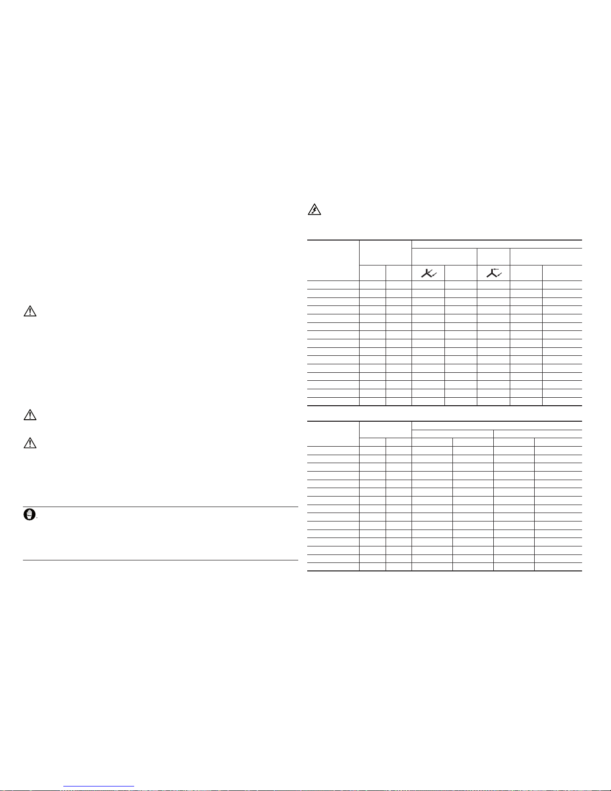
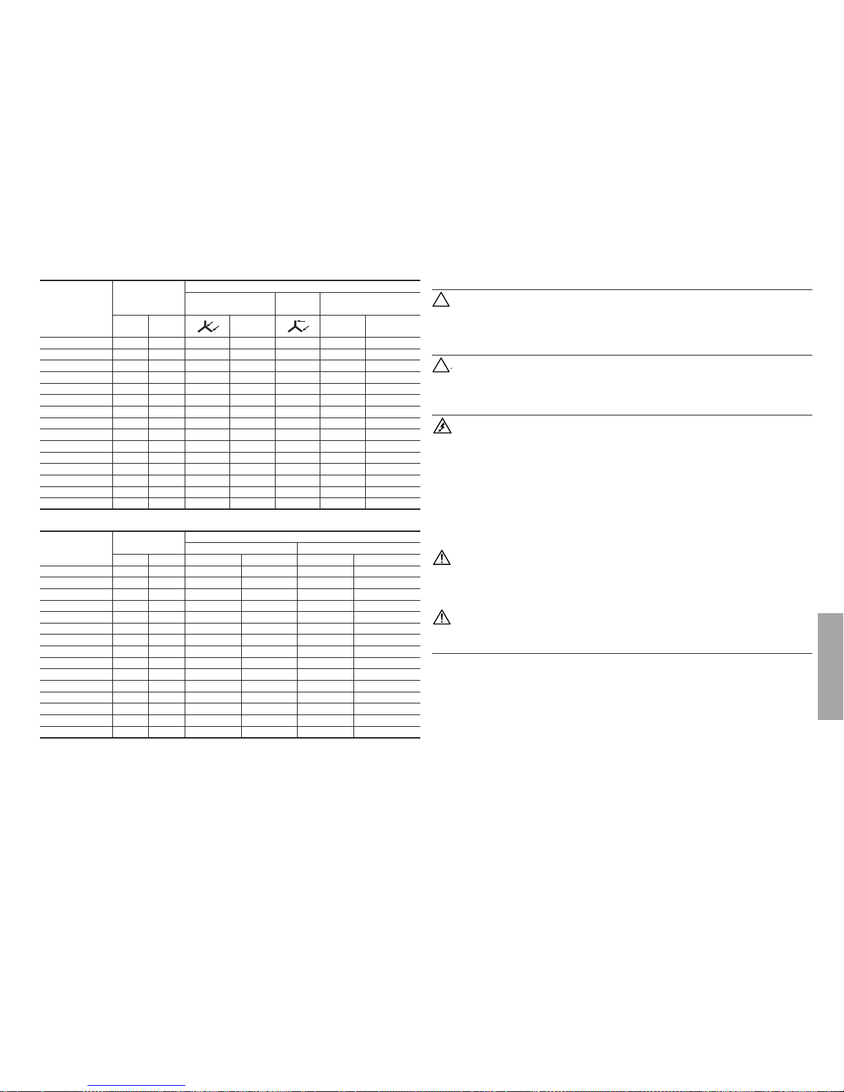
Tipo
kVA
Resistenza degli avvolgimenti Ω (20°C)
Alternatore
Avvolg.
ausiliario
Compound
50 Hz 60 Hz
Rotore I II
E1S10M G 5,5 7 1,80 19,50 2,24 0,270 1,550
E1S10M H 7 8,5 1,24 21,00 1,83 0,141 1,550
E1S10M I 9 11 0,92 22,70 1,75 0,101 1,550
E1S10L L 10 12 0,65 23,50 1,70 0,085 1,550
E1S11M A 10 12,5 0,75 22,30 1,60 0,075 1,350
E1S11M AS 11,5 14 0,63 22,30 1,54 0,070 1,350
E1S11M B 13,5 16,5 0,46 24,60 1,47 0,043 1,350
E1S13S C/2 16 20 0,48 10,26 1,20 0,052 0,648
E1S13M D/2 22 27 0,28 12,30 1,10 0,030 0,648
E1S13M E/2 27 32 0,23 14,00 0,90 0,019 0,648
E1S13S A/4 8 9,6 1,58 5,73 1,49 0,128 0,540
E1S13S B/4 10 12 0,97 6,82 1,31 0,083 0,540
E1S13M D/4 13 16 0,61 7,95 1,20 0,046 0,540
E1S13M E/4 16 19 0,46 9,72 1,07 0,030 0,540
E1S13M F/4 20 24 0,38 9,86 1,15 0,024 0,540
Tipo
kVA
Dati eccitazione rotore
A vuoto Pieno carico
50 Hz 60 Hz V
ECC
(V) I
ECC
(A) V
ECC
(V) I
ECC
(A)
E1S10M G 5,5 7 26 1,30 95 4,00
E1S10M H 7 8,5 29 1,30 111 4,10
E1S10M I 9 11 28 1,20 115 4,20
E1S10L L 10 12 30 1,30 115 4,50
E1S11M A 10 12,5 30 1,35 114 4,30
E1S11M AS 11,5 14 30 1,35 128 4,80
E1S11M B 13,5 16,5 34 1,35 133 4,45
E1S13S C/2 16 20 24 2,30 86 7,75
E1S13M D/2 22 27 24 1,90 92 7,50
E1S13M E/2 27 32 32 2,20 110 7,50
E1S13S A/4 8 9,6 20 3,35 56 7,80
E1S13S B/4 10 12 22 3,20 62 7,50
E1S13M D/4 13 16 26 3,15 76 7,70
E1S13M E/4 16 19 33 3,30 89 7,50
E1S13M F/4 20 24 35 3,35 95 7,70

- 7 -
6. TENSIONI E FRE QUENZE DI EROGA ZIONE NEGLI ALTERNATORI TRIFAS I
I normali alternatori sono previsti per erogare le seguenti tensioni:
⇒ 400 V a 50 Hz opp ure 480 V a 60 Hz co n collegament o stella con neu tro.
⇒ 230 V a 50 Hz oppur e 276 V a 60 Hz con collega mento triang olo.
7. SERVIZIO MONOFASE DEGLI ALTERNATORI TRIFASE
La potenza in monofase che può essere erogata in servizio continuo è circa 0,65 volte quella nel
funzionamento in trifase s e si usa la tensione concatenata sulla fase ri nforzata (bianca) e 0,6 volte
(E1S10/E1S11), 0, 4 (E1S13) se si u sa la tensio ne di fase (nel co llegamen to a stella)
8. TARATUR A DELLA TENS IONE E DELL A VELOCITÀ DI R OTAZIONE
Le operazioni di taratura devono essere eseguite esclusivamente da personale qualicato poiché
esiste il pericolo di folgorazione.
Il contro llo della tensi one di uscit a dell’alterna tore deve ess ere eett uato alla velocità di rotazione nominale (30 00 giri/1’
per gli alt ernatori a 2 po li e 1500 giri/1’ per q uelli a 4 poli). Nor malmente gli al ternatori so no tarati in f abbrica per e rogare
la tensione nominale. Leggeri scost amenti della tensione di uscita possono dipendere dal fatto che la velocità di rotazione
è divers a da quella n ominale.L a tension e di uscit a infatt i varia (att orno alla ve locità n ominale) in mo do quasi pr oporzi onale
alla velocità di rotazione. Nel caso che ad una determinata velocità di rotazione si voglia correggere la tensione a vuoto
dell’alternatore è necessario agire sul traferro del compound come descritto di seguito (gura 10).
1) A llentare il se rraggio dei du e dadi N.
2) M odicare lo s pessore del t raferro ten endo presen te che
:
a) aumentandolo la tensione cresce.
b) diminuendolo la tensione diminuisce.
Piccole variazioni della tensione si possono ottenere assestando dei leggeri colpi con un mar tello sulla parte mobile
del compound o fac endo leva con un cacciavite i n modo aumentare o d iminuire lo spes sore del trafer ro. Qualora
la variazione di tensione richiesta superi il 5% è necessario procedere alla sostituzione dell’isolante T che forma il
trafer ro con uno di spe ssore adegu ato.
3) A regolazione eettuata serrare denitivamente i due dadi N.
ATTENZIONE: Per un corretto funzionamento dell’alternatore non scostarsi (con la tensione) più del
5% rispe tto al valor e indicato i n targa.
9. NOTE GENERA LI
Funzionamento in ambienti particolari
Nel caso si usi l’alternatore in un gruppo insonorizzato fare attenzione che l’aria aspirata sia sempre quella fresca in
entrat a; ciò si ottie ne sistemand olo vicino al la presa d’aria c on l’esterno. In oltre biso gna tener conto c he la quantità d ’aria
richiesta dall’alternatore è di:
4 m3/min. pe r i modelli E1S10
5 m3/min. pe r i modelli E1S11
10 m3/min. pe r i modelli E1S13
CUSCINETTI
I cuscinetti degli alternatori E1S sono autolubric ati e quindi non richiedono manutenzioni per un periodo di funzionamento
superiore alle 10000 ore. Quando si deve procedere alla revisione generale del gruppo elettrogeno è consigliabile lavare
i cuscin etti con ada tto solvente.
Tipo di cuscinetto
Alternatore Lato accoppiamento Lato opp. accoppiamento
E1S10 630 5-2Z- C3 620 4-2Z- C3
E1S11 6 207-2Z- C3 6 205-2 Z-C3
E1S13 620 8-2Z- C3 63 05-2Z- C3
COLLETTORI AD ANELLI, PORTASPAZZOLE E SPAZZOLE
Il comple sso collettore-po rtaspazzo le-spazzol e è dimensionato e studiato p er garantire un serviz io sicuro e prolungato.
Pertanto durante l’uso dell’alternatore non sono richieste operazioni particolari di manutenzione a questo sistema per
almeno 20 00 ore di ser vizio negli al ternatori a 2 po li e 4000 ore i n quelli a quatt ro poli.
Nel caso si notasse però un comportamento irregolare dell’alternatore con diseccitazione casuale dell’alternatore ed
irregolarità nella erogazione della corrente elettrica è necessario attuare le seguenti semplici operazioni.
1)
contro llare lo stato d i pulizia del sis tema collet tore-spa zzole ed il lor o corretto a ssetto mec canico,
2) controllar e che le spaz zole siano p osiziona te in modo che p er tutt a la loro larg hezza ap poggino e ntro la supe rcie de gli
anelli,
3) c ontrollare lo s tato delle sp azzole ed eve ntualmente so stituirl e se usurate.
PONTI A DIODI (Figura 11)
Normalment e vengono usat i dei ponti a diod i previsti pe r 25A - 800V.
Verica dei ponti a diodi
La verica dei singoli diodi componenti il ponte di raddrizzamento può essere eseguita sia con un ohmetro che con
una batteria e relativa lampada come qui di seguito descritto. Un diodo è da ritenersi regolarmente funzionante
quando
- Con un ohme tro si veric a che la resist enza è molto bas sa in un senso e m olto alta nell ’altro.
- Con batteria e lampada (previ sta per la tensione della batteria) si veric a che l’accensione della lampada avviene
solamen te in uno dei du e collegame nti possi bili come ill ustrato i n gura 12: A = Lamp ada acces a, B = Lampad a
spenta.
Nota per lo smontaggio: p rima di estr arre il rotore d alla cassa è ne cessario to gliere il por taspazzo le.
Italiano

- 8 -
1. SAFETY INSTRUCTIONS
Befor e using th e genera ting set i t is neces sary t o read the g enerat ing set an d altern ator ”Use a nd Maint enance
Manual” and to follow the recommendations below.
⇒ Safe an d ecient p erform ance may be ac hieved onl y if the mach ines are use d correc tly, in comp liance
with the instructions provided by the relevant use and maintenance manuals and safety regulations.
⇒ An electric shock may cause serious personal injury or even death.
⇒ Do not remove either the terminal board cover or the alternator protection grid before the alternator
has come to a complete stop and the generating set starting system has been deactivated.
⇒ Only competent and qualied personnel should carr y out the maintenance of the generating set.
⇒ Do not wear loose garments when working near the generating set.
⇒ People i n charge o f operat ing the se t must alw ays wear pr otect ive gloves a nd safe ty shoes . In the even t
that the g enerator, or th e whole gene rating set, n eeds to be lif ted from th e oor, the opera tors must
also wea r a safety he lmet.
The person responsible for the installation of the generating set must make sure that all the necessary
safety arrangements are in place in order to make the whole plant compliant with current local safety
regulations (earthing, contact protection, explosion and re safety measures, emergency stop, etc.…)
Safet y warnings. S afety not ices used in thi s manual have the f ollowing mean ing.
IMPORTANT! Refers to dangerous or risky operations that may cause damage to the product.
CAUTION! Refers to dangerous or risky operations that may damage the product or cause personal in-
jury.
WARNING! Refers to dangerous or risky operations that may cause serious personal injury or even death.
DANGER! Refers to an immediate risk that may cause serious personal injury or death.
2. ALTERNATOR DESCRIPTION
The E1S serie s includes thre e-phase 2/4 pole s alternators w ith brushes eq uipped with an au xiliary wind ing (loaded on a
compound) which ensures voltage regulation.
They are manufactured in compliance with EN 60034-1, EN 60204 -1, EN 55014-1, EN 55011, EN61000- 6-2, EN 61000-6 -4
speci cations, as we ll as with the 200 6/95/CE, 2004/108 /CE, and 2006/42/C E directives.
Ventilation: Axial with ai r inlet on the non -drive end si de .
Protection. Standard I P 21. IP 23 on request .
Direction of rotation. Both direc tions are al lowed.
Electrical features. Insulation components are made with class H material, for both stator and rotor. Windings are
tropicalized.
Power val ues.
They ref er to the followi ng conditions: a mbient tempera ture up to 40°C, al titude up to 1000 m
. above sea-level,
continu ous duty at
Cosф
= 0.8.
Overloads
A 10% over load for one ho ur every six ho ur is normally a ccepted.
Mechanical features
Casing a nd covers ar e made of alumi nium alloy wh ich holds ou t against v ibratio ns. The shaf t is made of hi gh-tensil e steel.
GUASTO CAUSE INTERVENTI
Alternatore non si eccita
1) Insuciente tensione residua
2) Interruzione di un collegamento
3) Ponte a diodi rotante guasto
4) Velocità insuciente
5) Guasto negli avvolgimenti
6) Cattivo contatto con le spazzole
1) Eccitare il rotore utilizzando una batteria
2) Ripristinare il collegamento
3) Sostituire il ponte a diodi
4) Intervenire sul regolatore di giri del
motore primo
5) Controllare le resistenze e sostituire la
parte avariata
6) Pulire e controllare il collettore ad anelli
Tensione a vuoto bassa
1) Velocità ridotta
2) Cattivo contatto delle spazzole
3) Avvolgimento guasto
4) Ponte a diodi guasto
1) Riportare il motore prima a velocità
nominale
2) Controllare, pulire o sostituire le
spazzole
3) Controllare la resistenza e sostituire la
parte in avaria
4) Sostituire il ponte a diodi
Tensione corretta a vuoto, ma
troppo bassa a carico
1) Velocità ridotta a carico
2) Compound guasto
3) Avvolgimento del rotore difettoso
4) Carico troppo elevato
1) Intervenire sul regolatore di giri del
motore
2) Controllare ed eventualmente sostituire
il compound
3) Controllare la resistenza dell’ avvolg. del
rotore e, se guasto, sostituire il rotore
4) Intervenire sul carico per ridurlo
Tensione corretta a vuoto, ma
troppo alta a carico
1) Presenza di condensatori sul carico
2) Compound guasto
3) Collegamento delle fasi errato
1) Ridurre il carico capacitivo
2) Controllare ed eventualmente sostituire
il Compound
3) Controllare e correggere il collegamento
delle fasi
Tensione instabile
1) Massa rotante troppo piccola
2) Velocità irregolare
3) Cattivo contatto sul collettore
1) Aumentare il volano del motore primo
2) Controllare e riparare il regolatore di giri
del motore primo
3) Pulire e controllare il collettore ad anelli
e le spazzole
Funzionamento rumoroso
1) Accoppiamento meccanico difettoso
2) Cortocircuito su qualche avvolgimento
3) Cuscinetto difettoso
1) Controllare e/o modicare
l’accoppiamento
2) Controllare gli avvolgimenti e/o il carico
3) Sostituire il cuscinetto
ENGLISH

- 9 -
The roto r is particu larly sturd y to hold out agai nst the runaway s peed of the dri ve motors.
It is equi pped with a d amping cag e which allo ws satis factor y operat ion even wit h single- phase, dis torted lo ads. Bear ings
have lifelong lubrication.
Operation in particular settings.
If the alternator is going to be used at more than 1000 m above sea-level, a 4% derating per each 500 m increase will
need to be o perated. If a mbient tempe rature exce eds 40°C a 4% der ating per eac h 5°C increas e will need to be o perated.
INSTALLATION AND START UP
The following start up and control operations should be carried out only by qualied personnel.
⇒
The alternator must be installed in a well ventilated room. Ambient temperature should not exceed standard
recommended values.
⇒
Parti cular attent ion must be pai d to ensure that a ir inlets and ou tlets are ne ver obstruc ted.
While installing the alternator it is important to avoid direct suction of warm air coming from the alternator’s outlet
and/or fr om the prime mo tor.
⇒
Before star ting up the alternator it is a dvisable to che ck (visually and manually) that a ll terminals in every term inal
board ar e properly c lamped and tha t the rotatio n of the rotor in n ot blocked in a ny way.
⇒
If the alternator has not been used for a long time, before star ting it up it is recommended to test t he windings
insulat ion resistan ce to earth, keep ing into account t hat every singl e part has to be is olated from th e others. This
particular checkup must be carried out using a “Megger” instrument at 500 V. c.c.. Normally, windings having
resist ance to earth ≥1 MΩ are co nsidered su ciently insu lated.
If windings re sistan ce is lower tha n 1 Ω , insulati on will have to b e restore d by dryi ng the wind ing (using, fo r example,
an oven at 60 °-80°C te mperatu re, or by makin g circula te through t he wiring a p roper val ue of curr ent obtain ed from
an auxil iary source). It is a lso necessa ry to verif y that the alter nator’s meta llic parts , and the mass of th e entire set
are conne cted to the ea rth circui t and that the lat ter satis es any applica ble legal requ irements
.
Mistakes or oversights concerning earthing may have fatal eects.
3. ASSEMBLING INSTRUCTIONS
Assembling should be carried out by qualied personnel after reading the manual.
B3/B14 Construction Form
The cons truction f orm B3/B14 requir es the use of a ex ible couplin g between th e drive motor an d the alternato r.
The ex ible coupling s hould not orig inate any axia l or radial forc es during ope ration, and wil l have to be mounte d rigidly on
the alternator shaft end. Please follow the instructions below while assembling:
1) App ly the exibl e coupling and t he adaptor on the a lternator as sh own in Figu re 1A.
When positioning the exible coupling, remember that once coupling is over the rotor has to expand itself axially
towards t he coupling lo cated on the non -driving en d. To make this possib le it is necess ary that af ter assemblin g the
shaft e nd is positio ned according t o the cover pat tern, as illust rated in Fi gure 1B, a nd related tab le.
2) P lace the relev ant exible c oupling on th e revolving pa rt of the die sel engine, as s hown in Figur e 2A.
3) Mount the coupling’s rubber blocks.
4) Coup le the alterna tor to the drive m otor by screwi ng, with suit able screws , the adaptor to th e motor (see Fig. 2B).
5) Fix, usin g appropriate rubber anti-vib ration dampers, the moto r-alternator unit to the common bed- plate. Special
attent ion must be pai d not to cause any s tretching t hat may aect t he natural ali gnment of the t wo machines.
6) Make sure that the alternator ’s non-driving end bearing has the recommended expansion allowance (min. 2 mm.)
and that i t is preloaded b y a preload spr ing.
B3/B9 Construction Form
This cons truction for m allows direct coupling of alternator and drive motor. Please follow the instructions below when
assembling:
1) Clam p the «C» cover o n the drive moto r, as illustrated i n Figure 3A.
2) Apply the tie r od (13) for the axial c lamping of th e rotor, and scr ew it tight on t he engine sha ft end as sh own in Figur e
3B.
3) Sec ure the alter nator to its cove r using the 4 bolt s as indicate d in Figure 4A.
4) Lock axiall y the rotor by pla cing the was her (50), and tighte n the self-l ocking nut (51) usi ng a torque spa nner (drivin g
torque 35 Nm f or M8 tie rod and 55 Nm f or M10 tie rod and 100 Nm f or M14 tie rod) (Figur e 4B).
Be fore placi ng the nut make s ure that the th readed par t of the tie rod s lides into th e rotor in ord er to
obtain a tight lock. Before assembling verif y that the cone-shaped coupling housing (on both alternator and en gine) are cle an and in good wo rking ord er.
B2 Construction Form
This construction form too allows direct coupling of alternator and drive motor. Please follow the instructions below
when assembling:
1) Che ck that the roto r is position ed correct ly, as illustra ted in Figure 5A .
2) Remove rotor’s locking components on the non-driving end.
3) Plac e the alternato r next to the dr ive motor, as illus trated in Fig ure 5B.
4)
Centre an d secure the s tator to the dri ve motor’s ang e, using suitab le screws, as sh own in Figure
6A.
5)
Centre an d secure, u sing appro priate sc rews, the co upling to t he drive mot or’s ywh eel work ing throug h the air out let,
as indic ated in Figure 6 B.
Turn the ro tor as shown in Fi gures 7A and 7B.
FINAL CONTROLS
To the term of all the overwrite couplings it is necessary to control the correc t axial positioning; it must
be veri ed that:
1)
Betwe en the end of non -drive end si de bearing and t he surface o f axial clampi ng exists a sp ace of:
2 mm for the a lternator s E1S10
3 mm for the a lternator s E1S11 ed E1S13
2) The br ushes ar e centred o n rings of t he collec tor.
4. USAGE
Power cables connections should be carried out by qualied personnel when the machine is completely
still a nd the power ca ble is disco nnected.
Voltage an d output frequ ency: These alternators are designed to supply only t he voltage and fr equency spec ied in the
rating p late.
5. WIRING DIAGR AMS (Figure 8)
Connections power cables:
The E1S series alternators can work with star/neutral connection and with delta connection. The
termi nal board will h ave therefor e to be connected as show n in Figure 9: A = Star w ith neutral co nnections; B = Delta connections.
English

- 10 -
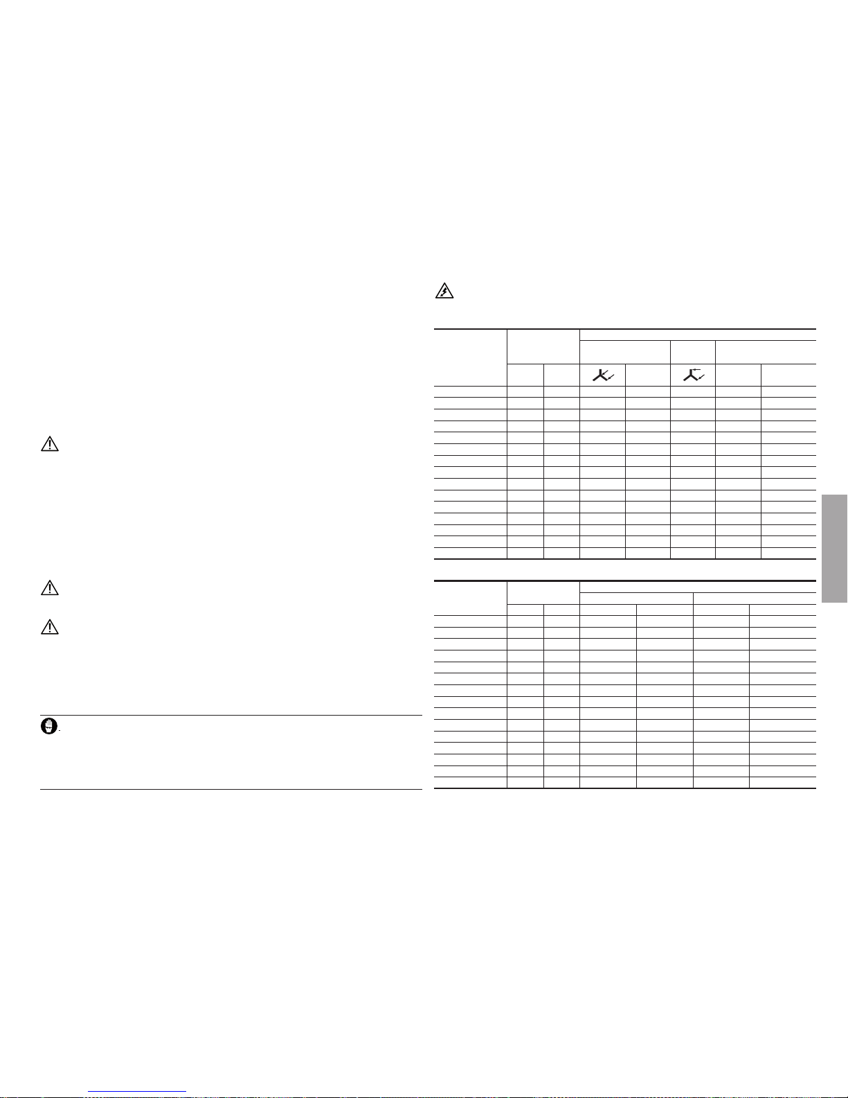
Type
kVA
Winding-resistance Ω (20°C)
Alternator
Aux
winding
Compound
50 Hz 60 Hz
Rotor I II
E1S10M G 5,5 7 1,80 19,50 2,24 0,270 1,550
E1S10M H 7 8,5 1,24 21,00 1,83 0,141 1,550
E1S10M I 9 11 0,92 22,70 1,75 0,101 1,550
E1S10L L 10 12 0,65 23,50 1,70 0,085 1,550
E1S11M A 10 12,5 0,75 22,30 1,60 0,075 1,350
E1S11M AS 11,5 14 0,63 22,30 1,54 0,070 1,350
E1S11M B 13,5 16,5 0,46 24,60 1,47 0,043 1,350
E1S13S C/2 16 20 0,48 10,26 1,20 0,052 0,648
E1S13M D/2 22 27 0,28 12,30 1,10 0,030 0,648
E1S13M E/2 27 32 0,23 14,00 0,90 0,019 0,648
E1S13S A/4 8 9,6 1,58 5,73 1,49 0,128 0,540
E1S13S B/4 10 12 0,97 6,82 1,31 0,083 0,540
E1S13M D/4 13 16 0,61 7,95 1,20 0,046 0,540
E1S13M E/4 16 19 0,46 9,72 1,07 0,030 0,540
E1S13M F/4 20 24 0,38 9,86 1,15 0,024 0,540
Type
kVA
Excitation of rotor
No load Full load
50 Hz 60 Hz V
EXC
(V) I
EXC
(A) V
EXC
(V) I
EXC
(A)
E1S10M G 5,5 7 26 1,30 95 4,00
E1S10M H 7 8,5 29 1,30 111 4,10
E1S10M I 9 11 28 1,20 115 4,20
E1S10L L 10 12 30 1,30 115 4,50
E1S11M A 10 12,5 30 1,35 114 4,30
E1S11M AS 11,5 14 30 1,35 128 4,80
E1S11M B 13,5 16,5 34 1,35 133 4,45
E1S13S C/2 16 20 24 2,30 86 7,75
E1S13M D/2 22 27 24 1,90 92 7,50
E1S13M E/2 27 32 32 2,20 110 7,50
E1S13S A/4 8 9,6 20 3,35 56 7,80
E1S13S B/4 10 12 22 3,20 62 7,50
E1S13M D/4 13 16 26 3,15 76 7,70
E1S13M E/4 16 19 33 3,30 89 7,50
E1S13M F/4 20 24 35 3,35 95 7,70
6. VOLTAGE AND OUTPUT FREQUENCY ON THE THREE PHASE ALTERNATORS
These al ternator s are design ed to supply t he voltage at:
⇒ 400 V at 50 Hz or 4 80 V at 60 Hz with s tar/neutral co nnection
⇒ 230 V at 50 Hz or 276 V at 60 Hz w ith delta con nection
7. SINGLE PHASE DUTY OF THREEPHASE ALTERNATORS
The output power in single-phase in continuous duty is approximately 65% of three-phase output
power in c ase of lin e-to-lin e voltage a nd 60% (E1S10/E1S11), 40% (E1S13) i n case of ph ase volta ge (star
connection).
8. VOLTAGE CALIBR ATION AND REVO LVING SPEED
The calibration of voltage should be carried out by qualied personnel only because of electrocution
hazard.
A checkout of the alternator’s output voltage should be carried out at the nominal revolving speed (3000 r.p.m. for the
alterna tors at 2 poles a nd 1500 r.p.m. for tho se at 4 poles).
The alter nators are c alibrated to di stribute t he nominal volt age.
Light dev iations of the o utput volt age can be caus ed by a revolvin g speed which i s dierent fr om the nominal o ne.
The outp ut voltage ch anges propo rtionally to t he revolving s peed.
To correct the no-load voltage of the alternator at a specic revolving speed, it is necessar y to act on the air gap of the
compou nd transfor mer as under de scribed (se e Figure 10).
1)
Loose th e tightening o f two screw nut s N.
2) Modify the height of air gap considering that:
a) in creasing i t the voltage g rows;
b) decrea sing it the vol tage lows dow n;
slight voltage variations they can be obtained with a small hammer and a screwdriver. In case the variation of
demande d voltage e xceeds 5% is ne cessar y to proce ed to the repl acement of t he insulati ng thickn ess (T) th at forms
the air gap.
3) Once regu lation is eec ted, tighte n the two scre w nuts N.
ATTENTION:
for a cor rect oper ation of the al ternator t he voltage ca n not exceed +/- 5% of th e plate value .
9. GENERAL NOT E
Operation in particular settings
If the alte rnator is goin g to be used with in a soundpro of generatin g set, make sure t hat only fresh a ir enters it.
This can b e ensured by pla cing the alter nator’s air inle t near the ext ernal air inta ke.
Moreover, remember that the quantit y of air required is:
4 m3/min. for E1S10 alternators
5 m3/min. for E1S11 alternators
10 m3/min. for E1S13 alternators

- 11 -
BEARINGS
The bear ings of the altern ators are self lu bricated an d therefore the y do not require mai ntenances for a p eriod of more
than 1000 0 hours.
When it is ne cessary to pr oceed to the gener al overhaul of the g enerating set i t is advisable to wa sh the bearings wi th a
proper solvent.
Bearing type
Alternator Driving end Non driving end
E1S10 630 5-2Z- C3 620 4-2Z- C3
E1S11 6 207-2Z- C3 6 205-2 Z-C3
E1S13 620 8-2Z- C3 63 05-2Z- C3
SLIPRINGS, BRUSH HOLDER AND BRUSHES
The set of c ollector- brush holde r-brushes i s designed to g uarantee a sa fe and long ser vice. There fore durin g the use of the
alterna tor partic ular operat ions of mainte nance to this sy stem are not dem anded for at le ast 2000 hou rs of servi ce for the
2 poles- alternator s and 4000 hou rs for 4 poles a lternator s.
In case of t he de-excit ation of the alt ernator and the co nsequent irr egularity o f the electr ic current sup ply it is necess ary
to carr y out the follo wing simple op erations:
1) Cle an the slip ring -brushes an d their corre cted mechan ical positi on.
2) Che ck the posit ion of the brush es; they must be l ean for all thei r width, withi n the surfac e of rings.
3) Che ck the brushe s and eventual ly replace them i f worn.
THREEPHASE DIODE BRIDGE Figure 11
Normal ly it comes use d the three-p hase diode br idge for 25A - 80 0V.
Checkout of three-phase diode bridge
The chec kout of single di ode valves of rec tier brid ge can be execut ed either with a n ohmmeter or wit h a battery
and relat ive lamp as desc ribed here b elow.
A diode valve works regularly when:
- the resi stance, calc ulated with an o hmmeter, is very l ow in one sense an d very high in th e other.
- with bat tery and lamp, it i s veried that th e ignition of the la mp is possible on ly with one of the t wo available con-
nections, as shown in Figure 12: A = Lamp O n, B = Lamp O.
Note for disassembly: B efore ext racting th e rotor from th e case it is nece ssary to re move the brush -holder.
FAU LT CAUSE SOLUTION
Alternator does not excite
1) Insucient residual voltage
2) Connection break
3) Broken three-phase diode bridge
4) Insucient speed
5) Windings breakdown
6) Poor contact with the brushes
1) Excite the rotor using a battery
2) Reset the connection
3) Replace three-phase diode bridge
4) Adjust speed regulator
5) Check winding resistance and replace
damaged part
6) Clean and check the collector
Low no-load voltage
1) Reduced speed
2) Poor brushes contact
3) Winding failure
4) Broken three-phase diode bridge
1) Reset speed for drive motor
2) Check, clean ar replace the brushes
3) Check resistance and replace
damaged part
4) Replace three-phase diode bridge
Correct no-load voltage but too
low with load
1) Low speed with load
2) Failed compound
3) Defective winding rotor
4) Load is too high
1) Adjust speed regulator
2) Check the compound and eventually
replace it
3) Check winding resistance and replace
the rotor if it is broken
4) Reduce the load
Correct no-load voltage but too
high with load
1) Appliances with capacitors on
the load
2) Air gap of compound too excessive
3) Defective winding compound
4) Wrong connection of phases
1) Reduce revolving speed
2) Reduce air gap of compound
3) Check winding resistance and replace
the compound if it is broken
4) Check and adjust the connection
of phases
Unstable voltage
1) Rotating mass too small
2) Uneven speed
3) Poor contact on collector
1) Increase the ywheel of the primary
motor
2) Check and repair speed regulator
3) Check and clean the slip-ring and
the brushes
Noisy Functioning
1) Bad coupling
2) Short circuit in windings or load
3) Faulty bearing
1) Check and correct coupling
2) Check windings and loads
3) Replace faulty bearing
English
- 12 -
1. MEDIDAS DE SECURIDAD
Antes de utilizar el grupo electrógeno es indispensable leer el manual de “ Uso y Manutención ” del grupo
electrógeno y del alternador, siguiendo las siguientes recomendaciones.
⇒ Un funcionamiento seguro y eciente se puede obtener solo si las máquinas son utilizadas en modo
correcto, siguiendo las indicaciones de los manuales de “Uso y Mantenimiento” y las normas relativas
a la seguridad.
⇒ Un choqu e eléctri co puede pro vocar graves d años, inclu sive la muer te.
⇒ Está prohibido quitar la tapas de las borneras y las protecciones del alternador mientras el mismo se
encuentre en movimiento o antes de haber desactivado el sistema de arranque del grupo electrógeno.
⇒ El mantenimiento del grupo deberá ser realizado exclusivamente por personal calicado o especializado.
⇒ No trabajar con ropaje suelto en las cercanías del grupo electrógeno.
⇒
Las personas encargadas a la movilización deberán usar en todo momento guantes y zapatos de trabajo.
Cada vez que el generador se deba alzar del suelo, las personas involucradas en dicha operación deberán
usar cascos de protección.
El instalador nal del grupo electrógeno es responsable de la predisposición de todas las medidas necesarias para obtener la conformidad del sistema con las normas locales vigentes de seguridad (puesta a
tierra, protección contra contac tos directos e indirectos, explosión, incendio, parada de emergencia, etc.).
Mensajes de seguridad. En este manual usaremos símbolos que tienen el siguiente signicado.
IMPORTANTE! Se reere a u na operació n riesgosa o p eligrosa que p uede provoc ar daños al prod ucto.
PRECAUCIÓN! Se ree re a una oper ación ries gosa o pelig rosa que pue de provoca r daños al pro ducto y he -
ridas a las personas.
ATENCIÓN! Se reere a una operación riesgosa o peligrosa que puede provocar graves heridas o eventualmente la muerte.
PELIGRO! Se re ere a un riesg o inmediat o que puede pr ovocar grave s heridas o la m uerte.
2. DESCRIPCION DEL ALTERNADOR
Los alternadores de la serie E1S son trifásicos a dos y a cuatro polos, con escobillas y bobinado auxiliar (cargado con un
transformador “compound”) que garantiza la autoregulación de los mismos.
Los generadores están construidos en conformidad con las normas EN 60034-1, EN 60204-1, EN 55014-1, EN 55011,
EN6100 0-6-2, EN 61000 -6-4 y a la s directiv as 2006/95/CE, 200 4/108/CE, y 2006 /42/CE.
Ventilación. Axial con aspiración del lado opuesto al acoplamiento.
Protecciones. De norma IP 21, a ped ido IP 23.
Sentido de rotación. Son admisibles los dos sentidos de rotación.
Características eléctricas. Los ais lantes son en cla se H tanto en el ro tor como en el est ator.
Los bobinados son tropicalizados.
Potencias. Están referidas a las siguientes condiciones: temperatura ambiente inferior a 40°C, altitud inferior a 1000 m
s.n.m., se rvicio con tinuativo a Cosф
= 0.8.
Sobrecargas
Se acept a una sobreca rga del 10% por 1 hor a cada 6 horas.
Características mecánicas
Carcaza y tapas en aleación de aluminio de alta resistencia a las vibraciones
Eje en acer o de alta res istencia . Rotor robu sto, apto pa ra resist ir la veloci dad de emba lamiento de l motor, pose e además jaul a
de amortiguamiento que permite un buen funcionamiento de la máquina aun con cargas de alta distorsión.
Rodamientos lubricados de por vida.
Funcionamiento en ambientes particulares:
Si el alter nador tiene que f uncionar a una a ltitud super ior a los 1000m s.n .m es necesar io reducir la pot encia de salida u n
4% por cada 5 00 m de increme nto.
Cuando la temperatura ambiente es superior a 40°C se debe reducir la potencia entregada por el alternador del 4% por
cada 5°C de incremento.
PUESTA EN MARCHA
Las siguientes operaciones de control y puesta en marcha deberán ser realizadas solo por personal calicado.
⇒ El alte rnador deber á ser instalad o en un local con po sibilidad de int ercambio de ai re atmosfér ico para evita r que la
temperatura ambiente supere los valores previstos por las normas.
⇒ Es necesario prestar atención de manera que las aberturas previstas para la aspiración y descarga del aire en el
alternador no se encuentren nunca obstruidas. Es importante además que el posición del alternador evite la aspiración
de su prop ia descarga d e aire caliente o d e aquella del mo tor primario .
⇒
Antes de la puesta en marcha es necesario controlar ocular y manualmente que todos los bornes de las diferentes
placas s e encuentre n bien ajustad os, y que no exis ta ninguna opo sición a la rot ación del roto r.
Cuando el alternador haya permanecido por largo tiempo inutilizado, antes de la puesta en marcha es necesario
contro lar la resis tencia de ai slamiento d e masa de tod os los bobi nados, ten iendo siem pre prese nte que se deb e probar
cada bobinado singularmente aislado de los otros.
Dicho control se deberá realizar con un instrumento denominado Megger y a una tensión de medida de 500V c.c.
Normal mente se consi dera suci ente un valor de r esistenc ia con respe cto a masa ≥ 1 MΩ Si e l valor medid o es inferi or,
será nec esario rest ablecer el aisl amiento secan do el bobinado po r medio de un horn o a una temperatu ra de 60-80°C
(o enventualmente haciendo circular un valor de corriente eléc trica obtenida por una fuente auxiliar).
Es necesar io además, que t odas las par tes metálic as del alter nador y la masa d el grupo com pleto estén c onectad as al
circuito de tierra en conformidad con las normas
vigentes.
Errores u olvidos en la conexión de tierra pueden provocar consecuencias mortales.
3. ISTRUCCIONE S PARA EL MONTAJE
Il montaje debe ser realizado por personal calicado después de la lectura de este manual.
Para la fo rma const ructiva B3/ B14
Dicha fo rma constr uctiva nece sita de una junt a elástica e ntre motor pri mario y alter nador.
Esta junta no deberá producir fuerzas axiales ni radiales durante el funcionamiento, deberá montarse rígidamente sobre
la part e saliente del ej e del alternad or.
Se aconseja seguir las siguientes operaciones:
1) Aplicar so bre el altern ador la semi- junta y la camp ana de alineami ento como se mue stra en la gura 1A.
En el mont aje de
la semi-junta tener presente que el rotor, una vez terminado el acoplamiento, tiene que tener al posibilidad de dilatarse
axialm ente hacia el lado d el cojinete opue sto al acoplami ento; para que es to sea posible es n ecesario que, a m ontaje
termina do, la parte sa liente del eje se e ncuentre en un a posición com o indicada en la gura 1B y tabla respectiva.
2) A plicar en la par te rotativ a del diesel la re spectiv a semi-junta c omo se indica e n la gura 2A.
3) Montar las cuñas elásticas de la junta.
4) Aco plar el alterna dor al motor pri mario jando co n los tornillos r espectiv os la campana de ac oplamiento (Ve r gura
2B).
ESPAÑOL
- 13 -
5) Fijar con an tivibra ntes adec uados el conj unto motor-a lternado r a la base, con pa rticul ar precauc ión de evit ar tension es
que tiendan a deformar el natural alineamiento de las dos máquinas.
6) Observar que el cojinete del lado opuesto al acoplamiento del alternador tenga previsto un espacio de dilatación (mínimo
2 mm) y se encue ntre cargad o con el resor te de precarg a.
Para la fo rma const ructiva B3/ B9
Esta forma constructiva prevee el acoplamiento directo entre motor y alternador. Se aconseja seguir las siguientes
operaciones:
1) F ijar la tapa «C » al motor prima rio como indic ado en la gura 3A.
2) Aplicar el tirante (13) para jar axialmente el rotor, enroscando a fondo sobre la parte saliente del eje motor como
representado en la gura 3B.
3) F ijar el alterna dor a su tapa con su s 4 tornillos re spectivo s como indica do en la gura 4A.
4) Fij ar axialmente el r otor aplicando la a randela (50) y la tuerc a (51) co n una llave dinamomè trica (cupla de ap riete 35
Nm para lo s tirantes M8, 55Nm p ara los tiran tes M10 y 100 Nm para los ti rantes M14), ver gura 4B.
An tes de aplic ar la tuerca , observa r que la part e roscada de l tirante ent re en el roto r permitien do una
segura operación de apriete. Antes del montaje, asegurarse que los acoplamientos cónicos (motor y
alternador) se encuentren sin pro blemas y per fectamente limpios.
Para la fo rma const ructiva B2
También esta forma constructiva prevee el acoplamiento directo entre motor y alternador. Se aconseja seguir las siguientes
operaciones:
1) Co ntrolar la cor recta pos ición del roto r con el auxilio d e la tabla indic ada en la gura 5A.
2) Quitar eve ntuales sis temas de blo queo del roto r que se encue ntren en el lad o opuesto al a coplamien to.
3) Ac ercar el alter nador al motor p rimario como i ndicado en la gura 5B.
4) Ce ntrar y jar con l os tornillos r especti vos el estator d el alternado r a la campana de l motor gura 6A.
5) Ce ntrar y jar con l os tornillos r especti vos la junta a dis cos del rotor al vo lante del moto r, utilizar para d icha operac ión
las aber turas de vent ilación como s e indica en la gura 6B.
Girar e l rotor tal co mo se muestr a en las gura s 7A e 7B.
CONTROLES FINALES
Al nalizar todos los acoplamientos descriptos precedentemente, es necesario controlar la correcta
posic ión axial; se d eberá veri car que:
1) E ntre el nal del c ojinete L.O.A (l ado opuesto ac oplamiento) y el to pe axial, exi sta una dist ancia de dilata ción de:
2 mm para lo s alternador es del tipo E1S10
3 mm para lo s alternado res del tipo E1S11 y E1S13
2) que las esc obillas se enc uentren cent radas sobre l os anillos del co lector.
4. USO
Las operaciones de conexión de los cables de potencia deben ser realizadas por personal calicado, con
la máquina completamente detenida y desconect ada de la carga.
Tensión y fre cuencia d e salida: E stos alter nadores e stán pre dispues tos para e ntregar e xclusiva mente la tens ión y la frec uencia
indica da en la tarjet a de datos.
5. ESQUEMA S ELECTRICO (Figur a 8)
Conexiones de los cables de potencia
Los alternadores E1S pueden funcionar con conexión a estrella con neutro o con conexión a triángulo.
La plac a de bornes pri ncipal debe rá conecta rse según el c aso como indi cado in gura 9: A = C onexión
estrella con neutro; B = Conexión Triángulo.
Type
kVA
Resistencia de los bobinados Ω (20°C)
Alternador
Bobinado
aux.
Compound
50 Hz 60 Hz
Rotor I II
E1S10M G 5,5 7 1,80 19,50 2,24 0,270 1,550
E1S10M H 7 8,5 1,24 21,00 1,83 0,141 1,550
E1S10M I 9 11 0,92 22,70 1,75 0,101 1,550
E1S10L L 10 12 0,65 23,50 1,70 0,085 1,550
E1S11M A 10 12,5 0,75 22,30 1,60 0,075 1,350
E1S11M AS 11,5 14 0,63 22,30 1,54 0,070 1,350
E1S11M B 13,5 16,5 0,46 24,60 1,47 0,043 1,350
E1S13S C/2 16 20 0,48 10,26 1,20 0,052 0,648
E1S13M D/2 22 27 0,28 12,30 1,10 0,030 0,648
E1S13M E/2 27 32 0,23 14,00 0,90 0,019 0,648
E1S13S A/4 8 9,6 1,58 5,73 1,49 0,128 0,540
E1S13S B/4 10 12 0,97 6,82 1,31 0,083 0,540
E1S13M D/4 13 16 0,61 7,95 1,20 0,046 0,540
E1S13M E/4 16 19 0,46 9,72 1,07 0,030 0,540
E1S13M F/4 20 24 0,38 9,86 1,15 0,024 0,540
Type
kVA
Datos excitación rotor
En vacio Plena carga
50 Hz 60 Hz V
EXC
(V) I
EXC
(A) V
EXC
(V) I
EXC
(A)
E1S10M G 5,5 7 26 1,30 95 4,00
E1S10M H 7 8,5 29 1,30 111 4,10
E1S10M I 9 11 28 1,20 115 4,20
E1S10L L 10 12 30 1,30 115 4,50
E1S11M A 10 12,5 30 1,35 114 4,30
E1S11M AS 11,5 14 30 1,35 128 4,80
E1S11M B 13,5 16,5 34 1,35 133 4,45
E1S13S C/2 16 20 24 2,30 86 7,75
E1S13M D/2 22 27 24 1,90 92 7,50
E1S13M E/2 27 32 32 2,20 110 7,50
E1S13S A/4 8 9,6 20 3,35 56 7,80
E1S13S B/4 10 12 22 3,20 62 7,50
E1S13M D/4 13 16 26 3,15 76 7,70
E1S13M E/4 16 19 33 3,30 89 7,50
E1S13M F/4 20 24 35 3,35 95 7,70
Español

- 14 -
Tipo di cojinete
Alternador Lado acoplamiento Lado opuesto acoplamiento
E1S10 630 5-2Z- C3 620 4-2Z- C3
E1S11 6 207-2Z- C3 6 205-2 Z-C3
E1S13 620 8-2Z- C3 63 05-2Z- C3
COLECTORES Y ANILLOS, PORTAESCOBILLAS Y ESCOBILLAS
El conjunto colectores-portaescobillas está dimensionado y estudiado para garantizar un servicio seguro y prolungado en el
tiempo. Por lo tanto, durante el normal uso del alternador no son necesarias particulares operaciones de mantenimiento del
conjunto por al menos 2.000 horas de funcionamento en los alternadores a 2 polos y de 4000 horas de funcionamento en los
alternadores a 4 polos. En el caso se hubiera la percepción de un comportamiento irregular del generador, con dexcitaciones
casuales y/o discontinuidad de corriente erogada será necesario efectuar las siguentes sencillas operaciones:
1) controlar la limpieza del conjunto colector-escobillas, asì como también el correcto montaje mecanico,
2) controlar que cada escobillasl se encuentre con toda su supercie apoyada sobre la supercie del anillo colector,
3) controlar el estado de las escobillas, sustituyendo las mismas en caso de desgaste excesivo.
PUENTE RECTIFICADO R (Figura 11)
Los puen tes utilizad os son del tipo 2 5A-800V.
Control del puente recticador
El control de los diodos que f orman el puente re cticador p uede ser efec tuado con un ohmet ro o eventualmente
con una lámpara. Un diodo es considerado sin anomalías cuando:
- Con un ohme tro se compru eba que la resis tencia es muy b aja en un sentid o, y muy alta en el sen tido invers o.
- Con batería y lámpara (prevista con tensión adecuada a la batería), se verica que el encendido de la lámpara se
obtien e solo en un se ntido de lo s dos posib les de cone xión, com o a continua ción indi cado in Fig ura 12: A = Lampa da
encendida, B = Lampada apagada.
Nota para el desmontaje:
Antes de de senlar el ro tor de la carcaz a es necesar io quitar el po rtaesco billas.
6. TENSIONI E FRE QUENZE DI EROGA ZIONE NEGLI ALTERNATORI TRIFAS I
Los alternadores están preparados para funcionar en las siguientes condiciones:
⇒ 400V a 50 Hz, o 4 80V a 60 Hz, en cone xión a estre lla con neutro.
⇒ 230V a 50 Hz, o 277V a 6 0 Hz, en conexi ón a triángulo.
7.
SERVICIO MONOFASICO EN ALTERNADO RES TRIFASICOS
La potencia monofásica que el alternador puede suministrar en servicio continuativo es
aproximadamente 0.65 del valor nominal del funcionamiento trifásico utilizando la tensión línea-línea,
y 0,6 (E1S10/E1S11), 0, 4 (E1S13)del valor nom inal si se u tiliza l a tensió n de fase (en la c onexió n a estre lla).
8.
AJUSTE DE L A TENSION Y VELOCI DAD DE ROTACION
Las operaciones de ajuste deberán ser realizadas exclusivamente por personal calicado, ya que en
las mismas existe el peligro de elec trocución.
El control de la tensión de salida del alternador se deberá efectuar a la velocidad de rotación nominal (3000 RPM para
genera dores a 2 polos y 150 0 RPM para gener adores a 4 polos).
Normal mente los alter nadores se ta ran en fábric a a la tensión nom inal.
Pequeñas variaciones de la tensión de salida pueden ser debidas a una velocidad de rotación diferente de la nominal.
Cuando a una dada velo cidad de rotació n se desee modicar la tensión en vac ío del alternado r, será necesario ajustar e l
entrehierro del transformador de regulación “compound” como indicado a continuación (gura 10):
1) Desenrosc ar, sin quitarlos, los tornillos N
2) Modicar el espesor del entrehierro, considerando que:
a) incrementándolo, la tensión aumenta
b) disminuyéndolo, la tensión se reduce, pequeñas variaciones de tensión pueden ser obtenidas simplemente
con un martillo y destornillador. Cuando la variación requerida sea mayor del 5%, será necesario reemplazar el
espes or (T) que prod uce el entrehi erro.
3) Co n la regulació n obtenida, aju star denit ivamente los d os tornillos N .
ATENCION: para un c orrecto f uncionamie nto del altern ador, no variar la te nsión de salid a en más del 5% del val or
nominal indicado en tarjeta.
9. NOTAS GENERAL S
Funcionamiento en ambientes particulares:
En el caso e l alterna dor se utili ce dentro d e un grupo ins onoriz ado, es nece sario pre veer siemp re la aspir ación de air e fresco.
4 m3/min. para alternadores del tipo E1S10
5 m
3
/min. para alternadores del tipo E1S11
10 m
3
/min. para alternadores del tipo E1S13
COJINETES
Los cojin etes de los a lternado res E1S son auto lub ricado s y por lo tanto n o necesit an mantenim iento por un t iempo supe rior
a las 1000 0 horas. Cua ndo se debe rá realiza r una revis ación gen eral del gr upo elec trógeno e s aconseja ble lavar los c ojinete s
con un solvente apropiado.

- 15 -
1. MESURES DE SECURITE
Avant d’utiliser un grou pe électrogène il est nécessaire de lire le manuel “d’emploi et entretien“ du groupe élec-
trogène et de l’alternateur et suivre les instructions suivantes.
⇒ On peut avoir un fonc tionnement sûr et ecace seulement si les machines sont utilisées correctement,
c’est-à-dire en suivant les indications des manuels d’emploi et d’entretien relatifs.
⇒ Une décharge électrique peut causer des dommages très graves ou la mort.
⇒ Il est interdit d’enlever le capot de fermeture de la boîte à bornes et les protec tions de l’alternateu r
quand il est en mouvement ou avant d’avoir désactivé le système de démarrage du groupe électrogène.
⇒ L’entretien du groupe doit être eectué exclusivement par du per sonnel qualié et spécialisé.
⇒ Ne pas travailler avec des vêtements larges près du groupe électrogène.
⇒ Le pers onnel préposé doit to ujours por ter les gants de t ravail et les ch aussures de sé curité. Quan d le
génér ateur ou le g roupe co mplet do it être so ulevé, les o uvrier s doiven t utilis er le casq ue de prot ectio n.
L’installateur du groupe élec trogène est responsable de la prédisposition de toutes les mesures nécessaire s an que l ’insta llation s oit conf orme aux n ormes lo cales de s ûreté (mis e à terre, p rotect ion cont re
le contact, protections contre explosion et incendie, arrêt d’urgence, etc).
Messa ges de sécuri té. Dans le prés ent manuel les s ymboles uti lisés sont le s suivants.
IMPORTANT! Se réfère à une opération risquée ou dangereuse qui peut endommager le produit.
PRUDENCE! Se réfère à une opération risquée ou dangereuse qui peut endommager le produit ou blesser
les personnes.
ATTENTION! Se réfè re à une opérat ion risquée o u dangereus e qui peut cau ser de blessu res très grave s
ou la mor t.
DANGER! Se réfère à une opération à risque immédiat qui pourrait causer de graves blessures ou la mort.
2. DESCRIPTION DE L’ALTERNATEUR
Les alter nateurs d e la série E1S sont d es généra teurs tr iphasés à d eux et à quat re pôles, av ec balais et a vec bobina ge auxili aire
(chargé sur l e Compound ) qui assure l a régulati on de la tensio n et sont fa briqués e n conformi té aux norm es EN 60034-1, EN
60204-1, EN 55014-1, EN 55011, EN6100 0-6 -2, EN 61000-6 -4 et au x direc tives 200 6/95/CE, 200 4/108/CE, e t 2006/42/CE .
Ventilation. Axiale à l’aspi ration du côté op posé à l’accoup lement.
Protection. Standard I P 21. Sur demande IP 23.
Sens de rotation. Les deux sens de r otations so nt possibles .
Caractéristiques électriques. Les iso lations sont r éalisés en Cl asse H soit po ur le stator q ue pour le roto r. Les bobinage s
sont tropicalisés.
Puissances. Se réfèrent aux conditionnes suivantes: température ambiante maximum de 40°C, altitude maximum de 1000
m. au dessu s du niveau de mer, ser vice conti nu à Cosф
= 0.8.
Surcharges: L’alternateur peut accepter un surcharge du 10% pendant une heure chaque 6 heures.
Caractéristiques mécaniques
La carc asse et les cou vercles sont e n alliage d’alumi nium qui résis te aux vibrat ions. L’axe est en acier à h aute résist ance.
Le rotor es t parti culière ment robus te pour ré sister à la vi tesse de f uite du moteu r princip al et avec une c age d’amor tissem ent
qui permet le bon fonctionnement aussi avec charges monophasés déformantes. Les roulements sont lubriés à vie.
PROBLEMAS CAUSAS ACCIONES
Alternador no se excita
1) Insuciente tensión residual
2) Interrupción de una conexión
3) Puente recticador averiado
4) Velocidad insuciente
5) Falla en algún bobinado
6) Mal contacto de las escobillas
1) Excitar el rotor con una batería
2) Restablecer la conexión
3) Substituir el puente recticador
4) Modicar el regulador de velocidad
5) Controlar las resistencias y reemplazar la
parte averiada
6) Limpiar y controlar los anillos colectores
y escobillas
Baja tensión en vacío
1) Baja velocidad
2) Mal contacto de las escobillas
3) Falla en algún bobinado
4) Puente recticador averiado
1) Ajustar la velocidad del motor a su valor
nominal
2) Limpiar y controlar los anillos colectores
y escobillas
3) Controlar las resistencias y reemplazar la
parte averiada 4)
Substituir el puente recticador
Tensión normal en
vacío pero baja en carga
1) Baja velocidad en carga
2) Compound averiado
3) Bobina rotor defectuosa
4) Carga elevada
1) Ajustar el regulador de velocidad del motor
2) Controlar y/o substituir el compound
3) Controlar la resistencia y/o substituir
el rotor
4) Reducir la carga al valor nominal
Tensión normal en
vacío pero alta en carga
1) Condensadores en la carga
2) Compound averiado
3) Fases mal conectadas
1) Reducir la carga capacitiva
2) Controlar y/o substituir el compound
3) Controlar y corregir la conexión incorrecta
de las fases
Tensión inestable
1) Masa rotativa pequeña
2) Velocidad irregular
3) Mal contacto de las escobillas
1) Aumentar la masa volante del motor
2) Controlar y/o ajustar el regulador de giros
del motor
3) Limpiar y controlar los anillos colectores
y escobillas
Funcionamiento
ruidoso
1) Acoplamiento mecánico defectuoso
2) Cortocircuito en algún bobinado
3) Cojinete defectuoso
1) Controlar y/o modicar el acoplamiento
2) Controlar los bobinados y/o la
carga
3) Substituir el cojinete
Français
FRANÇAIS
- 16 -
Fonctionnement dans un milieu particulier.
Si l’alternateur doit fonc tionner à plus de 1000 mètres d’altitude il est nécessaire de réduire la puissance débitée de 4% chaque
500 mèt res en plus. S i la tempéra ture ambia nte est sup érieure à 4 0°C on doi t réduire la p uissance d e 4% chaque 5° C en plus.
LA MISE EN SERVICE
Les opérations de contrôle pour la mise en service indiquées ci-après doivent être exécutées seulement
par du personnel qualié.
⇒ L’al ternateur d evra êtr e monté dans un e ndroit aé ré pour emp êcher que la t empérat ure ambian te dépasse l es valeur s
prévues dans les normes.
⇒ Il faut aus si faire atten tion que les ouve rtures pour l ’a spiration et l’éch appement de l’air n e soient jamais bo uchés
et que l’alte rnateur soit m onté de façon à év iter l’aspirati on de l’air chaude é mis par le même alt ernateur et/o u par
le moteur principal.
⇒ Avant la mise en s ervice i l est néce ssaire d e contrôle r visuell ement et man uelleme nt si toutes l es borne s des diér entes
boites à b ornes sont se rrées corr ectement e t qu’il n’existe au cun empêche ment à la rotati on du rotor.
Si l’alternat eur a demeu ré longte mps inac tif, avant de p rocéder à s a mise en ro ute, contr ôlez la rés istance d e l’isola tion
vers la ma sse des enrou lements en con sidérant que t outes les par ties à contr ôler devron t être isolé es des autres . Le
contrô le doit être fa it avec l’inst rument à 500 V. cour ant continu no mmé “Megger ”.
Normalem ent les enroule ments avec une ré sistance ver s la masse de ≥1 MΩ sont consi dérés comme su samment
isolés.
Si la valeur es t inférieure i l est nécessa ire de remett re l’isolatio n en état et séch er (utilisant par e xemple, un four à
60°-80 °C, ou en y fais ant circuler u n courant élec trique obt enu par une sour ce auxiliaire).
Il est aussi nécessaire de vérier que les partie métalliques de l’alternateur et la masse du groupe entier soient
connec tés au circui t de terre et que c elui-ci rép ond aux norme s de sécurité p révues par la l oi.
Erreu rs ou oubli s de la mise à terr e peuvent en traîner des c onséquen ces même mor tels.
3. INSTRUCTIONS POUR LE MONTAGE
Le montage doit être eectué par du personnel qualié et après lecture du manuel.
Pour la fo rme B3/B14
Pour la for me de construc tion B3/B14 il faut utiliser un joint élas tique entre le moteur principal e t l’alternateur. Le joint
élastique ne devra pas donner lieu à forces axiales ou radiales pendant le fonctionnent et doit être monté fermement sur
le bout de l ’arbre de l’alter nateur.
On conseille d’eectuer l’assemblage suivant les ins tructions ci-après :
1) Appliquez le demi-joint à l’alternateur et la cloche d’alignement comme montré par la g. 1A.
En positi onnant le demi- joint sur l’alter nateur n’oublie z pas que le rotor, apr ès le montage, do it avoir la possi bilité de
se dilate r sur l’axe en direc tion du roul ement côté oppo sé à l’accouplem ent.
Pour r endre pos sible cet te opérat ion il fau t que, à monta ge termin é, le bout d’arb re soit po sitionn é respec t aux usina ges
du couver cle comme mont ré par la g. 1B.
2) Mettez sur l a partie tou rnante du mote ur diesel le de mi-joint ap proprié com me montré par l a g. 2A.
3) Montez les bouchons élastiques du joint.
4) Co uplez l’alter nateur au moteur p rincipal en xant la cloch e d’alignement ave c les vis appro priées (voir g. 2B).
5) Fi xez avec des anti vibratoire s approprié s l’ensemble moteu r-alternateur a u socle en fais ant attentio n de ne pas créer
des tensions qui peuvent déformer l’alignement naturel des 2 machines.
6) C ontrôler s’ il y a une distanc e susante po ur la dilatatio n du roulement d u côté opposé à l ’accouplement (mi nimum 2
mm).
Pour la fo rme B3/B9
Cette f orme de constr uction prévoi t l’accouplement d irect entre le m oteur princip al et l’alternateu r. Po ur le montage on
vous conseille de procéder en suivant la méthode suivant:
1) F ixer le asque “C“ a u moteur princ ipal comme mon tré par la g. 3A.
2) Mon ter le tirant cent rale 13 pour le monta ge axial du rotor e n le vissant à fond s ur le bout d’arbre d u moteur comme
montré p ar la g. 3B.
3) F ixer l’alternat eur à son asque e n utilisant le s 4 boulons pré vus, comme mon tré par la g. 4A.
4) Bl oquer sur l’axe le ro tor en utilisa nt la rondelle (50) et v isser à fond l’écr ou autobloqu ant (51) avec une clef dyn amométriq ue (couple du serr age 35 Nm pour le tiran t M8, 55 Nm pour les tira nts M10 et 100 Nm pour le tir ant M14) (v oir
g. 4B).
Avant de mettre l’écrou contrôler que la partie letée du tirant centrale rentre dans le rotor permet tant
ainsi un blocage ferme. Avant le montage il faut vérier que les sièges coniques d’accouplement (de
l’alter nateur et du mo teur) soient e n ordre et pr opres.
Pour la fo rme B2
La forme B2 prévoit aussi l’accouplement direct entre l’alternateur et le moteur principal. Il est conseillé de procéder à
l’assemblage dans la façon suivante:
1) U tiliser la tab le montrée pa r la g. 5A pour cont rôler le corr ect positi onnement du ro tor.
2) E nlever éventue ls moyens de blo cage du rotor po sitionnés s ur le côté oppos é à l’accouplemen t.
3) A pprocher l’al ternateur au mo teur princip al comme montr é par la g. 5B.
4) Centrer et xe r le stator à la as que du moteur p rincipal ave c les vis prév ues comme mon tré par la g. 6A.
5)
Centrer et xer avec les vis prévues le joint du rotor avec le volant du moteur principal, en intervenant à travers des
ouverture pour le déchargement de l’air comme indiqué par la g. 6B.
Tourner l e rotor comme i ndiqué dan s les gures 7A et 7B.
CONTROLES FINALS
À la n de toutes les opérations d’accouplement indiqués ci-dessus il est nécessaire de contrôler le
correct positionnement axiale; on doit vérier que:
1) Entre la n du r oulement côté o pposé à l’accoup lement et la sur face de bloc age axial il y a un e distance de:
2 mm pour le s alternateur s E1S10
3 mm pour le s alternateu rs E1S11 e t E1S13
2) Que les ba lais soient cen trés sur les ann eaux du collec teur.
4. UTILISATION
Les opérations de connexion des câbles de puissance doivent être eectuées par le personnel préposé avec
la machine complètement fermée et pas connectée électriquement à la charge.
Tension et fréquence de débit. Nos alternateurs sont prévus pour débiter la tension et la fréquence indiquées sur la plaque.
5. SCHEMA DE CON EXION (Fig. 8)
Connexion des câbles d’alimentation.
Les alternateurs E1S peuvent fonctionner soit avec connexion étoile avec neutre que triangle. La boite
à bornes principale devra être donc connec tée (selon les cas) comme indiqué in g 9: A = Connexion
étoile avec neutre, B = Conexion triangle.
- 17 -
Type
kVA
Résistance des bobinages Ω (20°C)
Alternateur
Bobin.
aux.
Compound
50 Hz 60 Hz
Rotore I II
E1S10M G 5,5 7 1,80 19,50 2,24 0,270 1,550
E1S10M H 7 8,5 1,24 21,00 1,83 0,141 1,550
E1S10M I 9 11 0,92 22,70 1,75 0,101 1,550
E1S10L L 10 12 0,65 23,50 1,70 0,085 1,550
E1S11M A 10 12,5 0,75 22,30 1,60 0,075 1,350
E1S11M AS 11,5 14 0,63 22,30 1,54 0,070 1,350
E1S11M B 13,5 16,5 0,46 24,60 1,47 0,043 1,350
E1S13S C/2 16 20 0,48 10,26 1,20 0,052 0,648
E1S13M D/2 22 27 0,28 12,30 1,10 0,030 0,648
E1S13M E/2 27 32 0,23 14,00 0,90 0,019 0,648
E1S13S A/4 8 9,6 1,58 5,73 1,49 0,128 0,540
E1S13S B/4 10 12 0,97 6,82 1,31 0,083 0,540
E1S13M D/4 13 16 0,61 7,95 1,20 0,046 0,540
E1S13M E/4 16 19 0,46 9,72 1,07 0,030 0,540
E1S13M F/4 20 24 0,38 9,86 1,15 0,024 0,540
Type
kVA
Les données d’excitation de l’alternateur
A vide En charge
50 Hz 60 Hz V
EXC
(V) I
EXC
(A) V
EXC
(V) I
EXC
(A)
E1S10M G 5,5 7 26 1,30 95 4,00
E1S10M H 7 8,5 29 1,30 111 4,10
E1S10M I 9 11 28 1,20 115 4,20
E1S10L L 10 12 30 1,30 115 4,50
E1S11M A 10 12,5 30 1,35 114 4,30
E1S11M AS 11,5 14 30 1,35 128 4,80
E1S11M B 13,5 16,5 34 1,35 133 4,45
E1S13S C/2 16 20 24 2,30 86 7,75
E1S13M D/2 22 27 24 1,90 92 7,50
E1S13M E/2 27 32 32 2,20 110 7,50
E1S13S A/4 8 9,6 20 3,35 56 7,80
E1S13S B/4 10 12 22 3,20 62 7,50
E1S13M D/4 13 16 26 3,15 76 7,70
E1S13M E/4 16 19 33 3,30 89 7,50
E1S13M F/4 20 24 35 3,35 95 7,70
6. TENSION ET FR EQUENCE DE DEBIT DANS LES A LTERNATEURS TRIPHASES
Nos alternateurs sont prévus pour débiter la tension de:
⇒ 400 V à 50 Hz ou 4 80 V à 60 Hz avec conn exion étoile a vec neutre.
⇒ 230 V a 50 Hz ou 276 V à 60 Hz ave c connexion tr iangle.
7.
SERVICE MONOPHASE DES ALTERNATEURS TRIPHASES
La puissance en monophasé qui peut être débitée en service continu est environ 0,65 fois celle du
fonctionnement en triphasé avec tension ligne-à-ligne et 0,4 fois avec tension de phase (avec connexion
étoile).
8.
REGLAGE DE L A TENSION ET DE LA V ITESSE DE ROTATION
Les opération de réglage doivent être eectuées seulement par du personnel spécialisé à cause du
risque d’électrocution.
Le contrô le de la tension à l a sortie de l ’alternateur do it être eec tué à la vitesse de rotation nominale (3000 tour s/1’ pour
les alter nateurs à 2 pôl es et 1500 tours /1’ pour ceux à 4 pôle s).
Les alternateurs sont réglés dans l’usine pour débiter la tension nominale.
Petit éc arts dans la t ension de sor tie peuvent ê tre causés pa r une vitesse d e rotation di érente à celle n ominale.
La tensi on de sortie e st variable p roportio nnellement à la v itesse de rot ation.
Pour cor riger le vol tage à vid e de l’altern ateur à une vi tesse de r otation s péciq ue, il faut a gir sur l’entr efer du tr ansfor mateur
du compo und comme décr it ci-dess ous et en réfé rence à la gure 10.
1) D esserrer le s deux écrou s N.
2)
Modier l’hauteur de l’entrefer en considérant que:
a) en l’augmentant la tension croîte;
b) en le diminuant la tension baisse; des légères variations de tension peuvent être obtenues en disposant
simplem ent d’un petit ma rteau et d’un to urnevis. Dan s le cas où la varia tion de tension d emandée dépa sses le 5%
il est né cessaire de p rocéder à la su bstituti on de l’épaisseu r isolant (T ) qui forme l’ent refer.
3) A régulation e ectué ser rer déniti vement le deux é crous N.
ATTENTION: pour un correct fonctionnement de l’alternateur le voltage ne doit pas être plus ou moins
de 5% de la va leur indiqu ée sur la plaq ue
.
9. NOTES GENER AL
Fonctionnement dans un milieu particulier
Au cas où l’al ternateu r doit fair e partie d ’un groupe i nsonori sé, faire a ttentio n que l’air aspi rée par l’alt ernateur s oit toujo urs
l’air froi d d’arrivée; ça o n peut l’obtenir e n montant l’alter nateur prés d e la prise d’air ex terne.
En plus il f aut tenir compt e que la quantité d ’air nécessai re pour l’altern ateur est de:
4 m
3
/min. po ur les type s E1S10
5 m3/min. po ur les type s E1S11
10 m3/min. po ur les type s E1S13
ROULEMENTS
Les roulements de l’alternateur E1S sont autolubricants, donc l’entretien n’est pas nécessaire pendant une période de
plus de 100 00 heurs.
Français
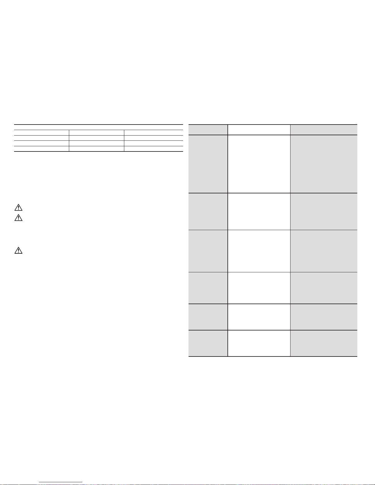
- 18 -
Type de roulement
Alternateur
Côté d’accouplement Opposé d’accouplement
E1S10 630 5-2Z- C3 620 4-2Z- C3
E1S11 6 207-2Z- C3 6 205-2 Z-C3
E1S13 620 8-2Z- C3 63 05-2Z- C3
COLLECTEURS AUX ANNEAUX, PORTEBALAIS ET BALAIS
Le group co llecteu rs aux annea ux -port e-balais - b alais est di mensionné e t étudié pou r garantir u n service s ûr et prolon gé.
Donc, pendant l’utilisation de l’alternateur, ne sont pas demandé des opérations particulières de manutention a ce système
pour au moins 2000 h eurs de service dans les alternateurs à deux pôle s et 4000 heurs dans ceux à quatre pô les. Dans le
cas où se vé rie une désexc itation de l’alter nateur et, donc, u ne irrégularité dans le dé bit de la courant électr ique, il est
nécessaire d’eec tuer les opérations suivantes :
1) Contrôler que l’ensemble collecteur-balais soit bien nettoyé et bien positionné.
2) Contrô ler la positio n des balais; ils d oivent appuy er dedans la sur face des anne aux pour toute l eur largeur.
3) Contrô ler l’état des ba lais et éventue llement les rem placer si détér iorés.
PONTS REDRESS EURS FIG. 11
On utili se des ponts re dresseur s prévue pour 2 5A - 800
Vérication de ponts redresseurs
La véricatio n de chaque diode qu i compose le pont de redressement peut être eec tuée soit avec le o hmmètre
que avec une batterie et la lampe relative comme décrit tout de suite. La diode fonctionne régulièrement quand:
- Avec le ohmm ètre on véri e que la résist ance est très b asse dans une se ns et très haut e dans l’autre.
- Avec la b atteri e et la lampe on v érie que l a lampe s’allum e seuleme nt avec une de d eux possi bles conn exions co mme
indiqué in g. 12: A = Lampe al lume, B = Lampe e teinte.
Note pour le désassemblage: Av ant d’extrair e le rotor de la ca isse il est néc essaire de dé monter le por te-bala
DEFAUT CAUSE DE DEFAUT OPERATIONS A EFFECTUER
L’alternateur ne s’excite
pas
1) Tension résiduelle insusante
2) Interruption d’une connexion
3) Défaut du pont redresseur
4) Vitesse insusante
5) Défaut dans le bobinage
6) Mauvais contact avec les balais
1) Exciter le rotor avec l’utilisation de la
batterie
2) Rétablir la connexion
3) Remplacer le pont redresseur
4) Modier le calibrage du régulateur de
vitesse
5) Contrôler la résistance et remplacer la
pièce détériorée
6) Nettoyer et contrôler le collecteur aux
anneaux
Tension à vide basse
1) Vitesse réduite
2) Mauvais contact des balais
3) Défaut du bobinage
4) Défaut du pont redresseur
1) Reporter le moteur principal à la vitesse
2) Contrôler, nettoyer ou remplacer les
balais
3) Contrôler la résistance et remplacer la
pièce détériorée
4) Remplacer le pont redresseur
Tension correcte à vide
mais basse en charge
1) Vitesse réduite en charge
2) Défaut du compound
3) Défaut des bobinages du rotor
4) Charge trop élevée
1) Modier le calibrage du régulateur
de tours
2) Contrôler et éventuellement remplacer
le compound
3) Contrôler la résistance du bobinage du
rotor et s’il est défaut le remplacer
4) Réduire la charge
Tension correcte à vide
mais élevée en charge
1) Présence des condensateurs en charge
2) Défaut du compound
3) Connexions des phases trompés
1) Réduire la vitesse de rotation
2) Contrôler et éventuellement remplacer
le compound
3) Contrôler et modier les connexions
des phases
Tension instable
1) Masse rotative trop petite
2) Vitesse irrégulière
3) Mauvais contact sur le collecteur
1) Augmenter le volant du moteur principal
2) Contrôler et réparer le régulateur de tours
3) Nettoyer et contrôler le collecteur aux
anneaux et les balais
Fonctionnement bruyant
1) Mauvais accouplement
2) Court-circuit sur les bobinages ou sur
la charge
3) Roulement défectueux
1) Contrôler et modier l’accouplement
2) Contrôler les bobinages et les
charges
3) Remplacer le roulement

- 19 -
1. SICHERHEITSMASSNAHMEN
Vor der Inbetriebnahme des Stromerzeugers ist es unerlässlich, die Bedienungs- und Wartungsanleitung
des Stromerzeugers und des Generators durchzulesen und die folgenden Empfehlungen zu berücksichtigen.
⇒ Ein sicherer und ezienter Betrieb ist nur dann gewährleistet, wenn die Maschinen gemäβ den
Bestimmungen der entsprechenden Handbücher „Bedienungs - und Wartungsanleitung“ sowie der
einschlägigen Sicherheitsvorschriften und Normen korrekt verwendet wird.
⇒ Lebensgefahr durch Stromschlag! Arbeiten an elektrischen Anlagen oder Betriebsmitteln nur in
abgeschaltetem, spannungslosen Zustand durchführen.
⇒ Das Entfernen der Verschlusskappe des Klemmegehäuses sowie der Schutzgitter des Generators ist
verboten, solange dieser in Bewegung ist und der Antrieb des Generators nicht sicher gegen selbsttätigen Anlauf gesichert ist.
⇒ Arbeiten an Elektrischen Anlagen und Betriebsmit teln dürfen nur von dafür ausgebildetem Fachpersonal
und entsprechend den geltenden nationalen Bestimmungen durchgeführt werden (in Deutschland u.a.
VDE - Vorsc hriften).
⇒ Der Aufenthalt im Bereich des Stromerzeugers ist nur mit entsprechender Sicherheitskleidung erlaubt.
Die einschlägigen Sicherheits-vorschriften der Berufsgenossenschaften sind unbedingt einzuhalten.
⇒ Personen, welche mit der Beförderung der Anlage vertraut sind, müssen immer Arbeitshandschuhe
und Sicherheitsschuhe tragen. Sollte der Generator oder das gesamte Aggregat vom Boden angehoben
werden, besteht Schutzhelmpicht.
Der Endinstallateur des Stromaggregats trägt die Verantwortung dafür, das alle er forderlichen Maβnahmen
getroen wurden, damit die Gesamtanlage den geltenden örtlichen Sicherheitsvorschriften entspricht.
(Erdung, Schutz gegen indirektes Berühren, Explosions- und Brandverhütungsvorrichtungen, Notabschaltung, usw.)
Sicherheitshinweise. Im vorliegenden Handbuch werden Symbole mit den folgenden Bedeutungen verwendet:
WICHTIG! Bezieth sich auf eine riskante oder gefärliche Operation, die das Produkt beschädigen.
ACHTUNG! Bezieh t sich auf ei ne riskant e oder gefä rliche Op eration , die zu schwe ren Verlet zungen ode r
eventuell zum Tod führen kann.
ACHTUNG!
Bezieh t sich auf ei ne riskan te oder gef ährlich e Operati on, die zu sch weren Verle tzungen o der even-
tuell zum Tod führ en kann.Personen Verletzungen zufügen kann.
GEFAHR! Bezieht sich auf ein unmittelbares Risiko, das zu schweren Verletzungen oder sogar zum Tod
führen könnte.
2. BESCHREIBUNG DES WECHSELSTROMGENER ATORS
Bei der Reihe E1S handelt es sich um Dreiphasen-Wechselstromgeneratoren mit zwei und vier Polen, mit Bürsten und
Hilfswicklung (auf Compound), welche die Spannungsregulier ung gewährleistet. Die Konstruktion entspricht den Normen
EN 60 034 -1, EN 60 204 -1, EN 5 5014 -1, EN 55011, EN61000- 6-2, EN 61000 -6-4 und nach den Richtlinien 2006/95/ CE,
2004/108/CE, und 2006 /42/CE gebaut.
Belüftung. Axiallüfter mit Ansaugen der Luft von der der Koppelung entgegengeset zten Seite.
Schutz. Standard IP 21. Auf A nfrage IP 23.
Drehrichtung. Es sind beide Drehrichtungen zulässig.
Elektrische Daten. Di e Isolierun g besteht sowo hl für Stator a ls auch für Roto r aus Material d er Klasse H. Die W icklungen
sind tropengeeignet.
Leistung. Unter folgenden Bedingungen. Umgebungstemperatur bis 40°C, Höhe maximal 1000 m ü.M., Dauerbetrieb
bei Cosф
= 0.8.
Überlast: Allgemein ist eine Überlast von 10% über 1 Stunde alle 6 Stunden zugelassen.
Mechanische eigenschaften.
Gehäuse und Abdeckungen sind aus vibrationsbeständiger Aluminiumlegier ung hergestellt. Die Welle ist aus hochwiderstandsfähigem Stahl. Der Rotor ist besonders robust, um der Schleuderdrehzahl der Zugmotoren standzuhalten und ist
mit einem Dämpfkäg ausgestattet, der einen einwandfreien Betrieb auch bei verzerrenden Einphasenladungen erlaubt.
Die Lager sind lebenslänglich geschmiert.
Betrieb in besonderen umgebungen.
Wenn der Generator in einer Meereshöhe über 1000m betrieben werden soll, ist eine Verringerung der erbrachten Leistung
von 4% pro 500 Meter Höhenanstie g notwendig. Wenn die Umgebungs temperatur über 40° C liegt, ist die erb rachte Leistung
des Gene rators um 4% pro 5 ° C Anstieg not wendig.
INBETRIEBNAHME
Folgende Operationen zur Kontrolle und Inbetriebnahme dürfen nur von qualiziertem Fachpersonal
ausgeführt werden.
⇒ Der Genera tor ist in ein em Raum zu in stallie ren, der die M öglichke it eines Lu ftaus tausch s mit der Atmo sphäre bie tet,
um zu verhindern, dass die Umgebungstemperatur die von den Normen vorgesehenen Werte übersteigt.
⇒ Darauf achten, dass die zum Ansaugen vorgesehenen Önungen und der Luftabzug zu keinem Zeitpunkt verstopft sind
und dass d ie für das Auf stellen d es Generat ors verwe ndete Technik e in direkt es Ansauge n der vom selb en Generato r
und/oder Hauptmotor abgegebenen heißen Luf t verhindert.
⇒ Vor d er Inbetrie bnahme ist es n otwendig, mi ttels Sich t- und manueller Ko ntrolle alle r Klemmen der ve rschiede nen
Klemmenbretter deren einwandfreien Sitz und das behinderungsfreie Rotieren des Motors sicherzustellen. Sollte der
Genera tor über länger e Zeit nicht in Be trieb sein, i st vor der erneu ten Inbetri ebnahme der Iso lierwide rstand geg en
die Masse der Wicklungen zu kontrollieren, wobei darauf zu achten ist, dass jedes einzelne zu kontro llierende Teil von
den ander en abisol iert sei n muss. Dies e Kontrol le ist mit ein em 500 V. c.c. Ger ät durchz uführen, d as Megger g enannt
wird. Normalerweise werden diejenigen Wicklungen als ausreichend isoliert betrachtet, die einen Widers tandswert
gegen die Masse von ≥ 1 MΩ besitzen. Sollte der gemessene Wert geringer sein, ist eine Wiederherstellung des
Widerstandes durch Trocknen der Wicklung vorzunehmen, z.B. durch Verwendung eines Ofens bei 60-80°C (oder
indem man in diesem einen geeigneten Stromwert von einer Hilfsstromquelle ießen lässt.). Es ist notwendig, zu
prüfen, dass die metallischen Teile des Generators und die Masse des gesamten Aggregats an den Erdungskreislauf
angeschlossen sind und dass letzterer den gesetzlich vorgeschriebenen Bestimmungen entspricht.
Fehler oder Nachlässigkeiten bei der Erdung können tödliche Folgen haben.
3. MONTAGEANLEITUNG
Die Montage ist von qualiziertem Fachpersonal nach Lesen des Handbuchs durchzuführen.
Für die Ba uart B3/B14
Die Bauart B3/B14 er fordert die Ver wendung eines elastischen Verbindungsstücks zwischen Hauptmotor und Generator.
Das elastische Verbindungsstück entwickelt während des Betriebs axiale oder radiale Kräfte und wird steif an den Vorsprung
der Welle des Generators montiert. Es empehlt sich beim Zusammenbau in folgenden Phasen vorzugehen:
Deutsch
DEUTSCH

- 20 -
1) Das Halbverbindungsstück und die Ausrichtglocke am Generator wie in Ab b. 1A anbringen.
Beim Positionieren des Halbverbindungsstücks am Generator beachten, dass der Rotor bei komplettem Kuppeln
die Möglichkeit beibehalten muss, sich axial in Richtung des Lagers der Kupplung der gegenüberliegenden Seite
ausdehnen zu können; um dies zu ermöglichen, ist es notwendig, dass nach Beendigung der Montage der Vorsprung
der Welle hinsichtlich der Verarbeitung der Abdeckung wie in der Abbildung und in der ent sprechenden Tabelle 1B
positioniert wird.
2) Am rotierenden Teil des Dieselmotors das ent sprechende Halbverbindungsstück wie in Abb. 2A anbringen.
3) Die elastischen Dübel des Verbindungsstücks anbringen.
4) Den Generator an den Hauptmotor kuppeln, indem man mit den entsprechenden Schrauben die Kupplungsglocke
befestigt (siehe Abb. 2B).
5) Mit geeigneten Vibrationsschutz vorrichtungen die Gesamtheit aus Motor und Generator an der Basis befestigen und
darauf achten, dass keine Spannungen entstehen, welche tendenziell die natürliche Ausrichtung der beiden Maschinen
deformieren.
6) Darauf achten, dass das Lager der gegenüberliegenden Kupplungsseite den vorges ehenen Ausdehnungsraum (Minimum
2 mm) besit zt und durch d ie Vorspannfe der vorgesp annt ist.
Für die Ba uform B3/B9
Diese B auform si eht eine dir ekte Kupp lung zwi schen Haup tmotor un d Generat or vor. Es emp ehlt sich be im Zusamm enbau
wie folgt vorzugehen:
1) Abdeckung «C» an den Hauptmotor wie in Abb. 3A befestigen.
2) Die Zugstange (13) zur axialen Befestigung des Rotors anbringen, indem man diese vollständig an den Vorsprung der
Welle des Motors anschraubt, siehe A bb. 3B.
3) Den Generator an seine Abdeckung mit den 4 vorgesehenen Mutterschrauben wie in Abb. 2c befestigen.
4) Axia l den Rotor blocki eren, indem man die Unterlegschei be (50) anbringt und die selbs tblockierende Mutter (51) mit einem
dynamometrischen Schlüssel (Befestigungsdrehmoment 35 Nm für Zugstangen M8, 55 Nm für Zugstangen M10 und 100 Nm
für Zugstangen M14) befestig t (siehe Abb. 4B).
Vor dem Anbringen der Mutter darauf achten, dass der Gewindeteil der Zugstange in den Rotor eingeführt ist, um ein sicheres Blockieren zu ermöglichen. Vor der Montage sicherstellen, dass die konischen
Kupplungssitze (am Generator und Motor) gleichmäßig und gut sauber sind.
Hinsichtlich der Form B2
Auch diese Form sieht eine direkte Kupplung zwischen Motor und Generator vor. Es empehlt sich b eim Zusammenbau
wie folgt vorzugehen:
1) Die ko rrekte Posi tionierun g des Rotors m it Hilfe der in A bb. 5A aufgeführten Tabelle kontrollieren.
2) Eventuelle Blockiervorrichtungen des Rotors an der gegenüberliegenden Kupplungsseite ent fernen.
3) Den Gen erator an den Hau ptmotor wie i n Abb. 5B annähern.
4) Den Stator zentrieren und an den Flansch des Hauptmotors mit den entsprechenden Schrauben wie in Abb. 6A
befestigen.
5) Mit den entsprechenden Schrauben das Verbindungsstück des Rotors zentrieren und am Schwungrad de
s Hauptmotors
befestigen, indem den Zugang über die Luf tabussönungen benutzt, siehe
Abb. 6B
.
Drehe n Sie den Rotor, wie i n den Figuren 7A un d 7B gezeigt.
ABSCHLIESSENDE KONTROLLEN
Am Ende aller oben beschriebenen Koppelungsvorgänge ist die korrekte Positionierung der Achse zu
kontrollieren; d.h. es ist zu überprüfen:
1) Dass zwisch en dem Ende des L agers L.O.A. un d der Wand, an der die Ac hse befest igt wird, ein Fre iraum vorhand en
ist und z war von:
2 mm für Wechselstromgeneratoren E1S10
3 mm f ür Wechse lstromg enerato ren E1S11 und E1S13
2) Dass die Bürsten auf den Ringen des Kollektors zentriert sind.
4. ANSCHLUSS
Die Anschlussoperationen der Kraftstromkabel sind von Fachpersonal bei tatsächlich stehender und
elektrisch von der Ladung getrennter Maschine durchzuführen.
Spannung und betriebsfrequenz: Diese Generatoren sind voreingestellt, um ausschließlich die auf dem Datenschild
angegebene Spannung und Frequenz zu ent wickeln.
5. ELEKTRISCHE SCHALTKREISE (Abb. 8)
Anschluss der Kraftstromkabel
Die Wechselstromgeneratoren E1S können sowohl mit Sternschaltung mit Neutralleiter als auch mit
Dreieckschaltung betrieben werden.Das Hauptklemmenbrett ist demzufolge (je nach Ausführung) wie
in Abbildung 9: A = Sterns chaltung m it Neutrall eir; B = Dreie ckschal tung
Type
kVA
Elektrischer widerstand - Wicklung Ω (20°C)
Generatoren
Hilf-
swicklung
Compound
50 Hz 60 Hz
Rotor I II
E1S10M G 5,5 7 1,80 19,50 2,24 0,270 1,550
E1S10M H 7 8,5 1,24 21,00 1,83 0,141 1,550
E1S10M I 9 11 0,92 22,70 1,75 0,101 1,550
E1S10L L 10 12 0,65 23,50 1,70 0,085 1,550
E1S11M A 10 12,5 0,75 22,30 1,60 0,075 1,350
E1S11M AS 11,5 14 0,63 22,30 1,54 0,070 1,350
E1S11M B 13,5 16,5 0,46 24,60 1,47 0,043 1,350
E1S13S C/2 16 20 0,48 10,26 1,20 0,052 0,648
E1S13M D/2 22 27 0,28 12,30 1,10 0,030 0,648
E1S13M E/2 27 32 0,23 14,00 0,90 0,019 0,648
E1S13S A/4 8 9,6 1,58 5,73 1,49 0,128 0,540
E1S13S B/4 10 12 0,97 6,82 1,31 0,083 0,540
E1S13M D/4 13 16 0,61 7,95 1,20 0,046 0,540
E1S13M E/4 16 19 0,46 9,72 1,07 0,030 0,540
E1S13M F/4 20 24 0,38 9,86 1,15 0,024 0,540
Type
kVA
Daten Rotorerregung
Leerlaufspannung Leerlaufspannung
50 Hz 60 Hz V
ERR
(V) I
ERR
(A) V
ERR
(V) I
ERR
(A)
E1S10M G 5,5 7 26 1,30 95 4,00

- 21 -
E1S10M H 7 8,5 29 1,30 111 4,10
E1S10M I 9 11 28 1,20 115 4,20
E1S10L L 10 12 30 1,30 115 4,50
E1S11M A 10 12,5 30 1,35 114 4,30
E1S11M AS 11,5 14 30 1,35 128 4,80
E1S11M B 13,5 16,5 34 1,35 133 4,45
E1S13S C/2 16 20 24 2,30 86 7,75
E1S13M D/2 22 27 24 1,90 92 7,50
E1S13M E/2 27 32 32 2,20 110 7,50
E1S13S A/4 8 9,6 20 3,35 56 7,80
E1S13S B/4 10 12 22 3,20 62 7,50
E1S13M D/4 13 16 26 3,15 76 7,70
E1S13M E/4 16 19 33 3,30 89 7,50
E1S13M F/4 20 24 35 3,35 95 7,70
6.
VON DREIPHASEN-WECHSELSTROMGENERATOREN ABGEGEBENE SPANNUNGEN UND FREQUENZEN
Normalen Wechselstromgeneratoren sind für die Abgabe folgender Spannungen ausgelegt:
⇒ 400 V 50 Hz ode r 480 V 60 Hz bei Ste rnschaltu ng mit Neutral leiter.
⇒ 230 V 50 Hz oder 276 V 60 H z bei Dreieck schaltung .
7.
EINPHASENBETRIEB VON DREIPHASEN-WECHSELSTROMGENERATOREN
Die bei Einphasenbetrieb erzielbare Leistung beträgt bei Dauerbetrieb ca. 0,65 Mal diejenige des
Dreip hasenb etrie bs, falls v erket tete Span nung ver wendet w ird, un d 0,6 volte (E1S10/E1S11), 0,4 (E1S13)
Mal die des Dreiphasenbetriebs, falls die Phasenspannung (bei Sternschaltung) verwendet wird.
8.
KALIBRIERUNG VON SPANNUNG UND DREHGESCHWINDIGKEIT
Die Kalibrierung darf ausschließlich von qualiziertem Fachpersonal vorgenommen werden, da
Stromschlaggefahr besteht.
Die Kontrolle der Ausgangsspannung des Wechselstromgenerators muss bei Nenndrehzahl erfolgen (3000 U/min für
zweipolige und 1500 U/min für vierpolige Generatoren).
Normalerweise werden die Wechselstromgeneratoren im Werk für die Abgabe der Nennspannung kalibriert.
Leichte Abweichungen der Ausgangsspannung können davon abhängen, dass die Drehzahl nicht genau dem nominellen
Wert entspricht.
Hierbei ist zu berücksichtigen, dass die Ausgangsspannung fast genau proportional zur Drehzahl variiert (im Bereich der
Nenngeschwindigkeit).
Soll bei einer bestimmten Drehzahl die Leerlaufspannung des Wechselstromgenerators korrigiert werden, muss, wie
nachstehend beschrieben und auf der ne benstehend aufgeführten Abbildung näher erläuter t, der Luftspalt des CompoundTransformators reguliert werden (Abb. 10).
1) D ie beiden Mut tern N locker n.
2) D ie Höhe des Luf tspalts ä ndern, wobei d arauf zu achten i st,
a) dass die Spannung steigt, wenn der Spalt vergröbert wird,
b) während sie sinkt, wenn der Spalt verengt wird. Leichte Spannungsvariationen können schon mit Hilfe eines
kleinen Hammers und eines Schraubenziehers erzielt werden. Falls die erforderliche Spannungsvariation 5% übersteigt,
muss jedoch die Isolationsschicht (T) ersetzt werden, welche den Luftspalt bildet.
3) Nach Abschluss der Regulierung die beiden Muttern N endgültig festziehen.
ACHTUNG: Zur Gewährleistung des einwandfreien Betriebs des Wechselstromgenerators darf die eingestellte
Spannung um nicht mehr als 5% von dem auf dem Maschinenschild angegebenen Wert abweichen.
9. DIE G ENERELLE NO TE
Betrieb in besonderen umgebungen:
Sollte man den Generator in einem schalldichten Aggregat ver wenden, ist d arauf zu achte n, dass dessen a ngesaugte L uft
stets die am Eingang angesaugte Frischluft ist; dies erhält man dadurch, dass man diesen in der Nähe von Luf tönungen
aufstellt, die nach außen gehen. Außerdem ist darauf zu achten, dass die vom Generator benötigte Luftmenge wie folgt ist:
4 m3/min. bei de n Typen mit Höhe E1S 10
5 m3/min. bei de n Typen mit Höhe E 1S11
10 m3/min. bei de n Typen mit Höhe E1 S13
LAGER
Die Lager der Drehstromgeneratoren sind selbstschmierend und benötigen deshalb keinerlei Wartung für eine Betriebsdauer
von über 10000 Stunden. Wenn eine Generalüberholung des Stromaggregats vorzunehmen ist, wird empfohlen, die Lager
mit einem geeigneten Lösungsmittel zu reinigen.
Typ des lag ers
Generatoren
Antriebsseite
Nicht
angetrieben
E1S10 630 5-2Z- C3 620 4-2Z- C3
E1S11 6 207-2Z- C3 6 205-2 Z-C3
E1S13 620 8-2Z- C3 63 05-2Z- C3
KOLLEKTORRINGE, BÜRSTENTRÄGER UND BÜRSTEN
Die Baugruppe Kollektor-Bürstenträger-Bürsten ist derart dimensioniert und ausgelegt, dass ein sicherer und dauerhafter
Betri eb gewährleis tet wird.
Daher sind während des Gebrauchs des Wechselstromgenerators für mindestens 2000 Betriebsstunden bei zweipoligen
und 4000 Betriebsstunden bei vierpoligen Generatoren keine besonderen Wartungsmaßnahmen erforderlich. Sollte jedoch
ein unregelmäßiger Betrieb des Wechselstromgenerators mit plötzlicher Entregung und unregelmäßiger Stromabgabe
festgestellt werden, sind die folgenden, einfachen Maßnahmen durchzuführen:
1) D as System Kollek tor-Bürs ten auf Schmut z untersuc hen und ihre korr ekte mecha nische Ausri chtung prüf en.
2)
Prüfen, ob die Bürsten richtig positioniert sind und in ihrer ganzen Breite an der Ringoberäche anliegen.
3) Den Zustand der Bürsten prüfen und gegebenenfalls ersetzen, wenn Verschleiß vorliegt.
DIOD ENBRÜCKEN ABB. 11
Normalerweise werden Diod-enbrücken für 25 A-800 V verwendet.
Überprüfung der Diodenbrücken
Die Über prüfung der ein zelnen Dioden, au s denen sich die Gle ichrichterbr ücke zusammensetz t, kann sowohl mit
einem Ohmmeter als auch mit Batterie und Lampe entsprechend nachstehender Beschreibung erfolgen. Eine Diode ist
als funktionstüchtig zu betrachten, wenn:
- Mit einem Ohmmeter festgestellt wird, dass der Widerstand in einer Richtung sehr niedrig und in der anderen sehr
hoch ist;
- Mit Batterie und (zur Batteriespannung passender) Lampe festgestellt wird, dass die Lampe nur bei einer der
beiden möglichen Verbindungen aueuchtet, wie unten gezeigt in Abb. 12: A = Einge schalte te glühbir ne; B =
Deutsch

- 22 -
Auseschaltete glühbirne.
Anmerkung für die Demontage: Bevor der Rotor aus d em Gehäuse h erausgez ogen wird, mu ss der Bürs tenträge r
entfernt werden.
STÖRUNG URSACHE MAβNAHMEN
Wechselstromgenerator
wird nicht erregt.
1) Ungenügende Restspannung
2) Unterbrechung einer Verbindung
3) Diodenbrücke defekt
4) Geschwindigkeit unzureichend
5) Defekt in den Wicklungen
6) Schlechter Bürstenkontakt
1) Rotor mit Hilfe einer Batterie erregen
2) Verbindung wiederherstellen
3) Diodenbrücke austauschen
4) Drehzahlregler einstellen
5) Widerstände prüfen und defekte Teile
ersetzen
6) Kollektorringe reinigen und kontrollieren
Niedrige Leerlaufspannung
1) Reduzierte Geschwindigkeit
2) Schlechter Bürstenkontakt
3) Wicklung defekt
4) Diodenbrücke defekt
1) Kondensatorkapazität senken
2) Ersten Motor wieder auf Geschwindigkeit
bringen
3) Widerstand prüfen und defekte Teile ersetzen
4) Diodenbrücke ersetzen
Leerlaufspannung korrekt,
aber Lastspannung zu
niedrig
1) Reduzierte Geschwindigkeit bei
Lastzuschaltung
2) Compound defekt
3) Rotorwicklung defekt
4) Last zu hoch
1) Drehzahlregler einstellen
2) Compound prüfen und ggf. ersetzen
3) Widerstand der Rotorwicklung prüfen und,
falls defekt, den Rotor ersetzen
4) Last reduzieren.
Leerlaufspannung korrekt,
aber Lastspannung zu hoch
1) Kondensatoren auf Last
2) Compound defekt
3) Falsche Phasenverbindung
1) Drehgeschwindigkeit senken
2) Compound prüfen und ggf. ersetzen
3) Phasenverbindungen prüfen und korrigieren.
Spannung unstabil
1) Rotierende Masse zu klein
2) Unregelmäßige Geschwindigkeit
3) Schlechter Kontakt am Kollektor
1) Schwungrad des ersten Motors vergrößern.
2) Drehzahlregler prüfen und reparieren
3) Kollektorringe und Bürsten reinigen und
kontrollieren
Geräuschbildung bei
Betrieb
1) Schlechte Koppelung
2) Kurzschluss in Wicklungen oder Last
3) Defektes Lager
1) Kopplung kontrollieren und ändern
2) Wicklungen und Lasten kontrollieren
3) Lager ersetzen

- 23 -
PARTI DI RICAMBIO
SPARE PARTS
LISTA DE REPUESTOS
PIECES DETACHEES
ERSATZTEILE

- 24 -
E1S10M - E1S10L

- 25 -
Nº COD. RICAMBI SPARE PARTS LISTA DE REPUESTOS PIECES DETACHEES ERSATZTEIL
1 * CARC. CON STATORE FRAME WITH STATOR CARC. CON ESTATOR CARC. AVEC STATOR GEHÄUSE MIT STATOR
2A * INDUTT. ROTANTE B9 B9 ROTATING INDUCT. INDUCT. ROTANTE B9 ROUE POLAIRE B9 DREHANKER B9
2B * INDUTT. ROTANTE B14 B14 ROTATING INDUCT. INDUCT. ROTANTE B14 ROUE POLAIRE B14 DREHANKER B14
3B E10SE005A SCUDO POSTERIORE B9 E1S10M REAR SHIELD B9 E1S10M TAPA POSTERIOR B9 E1S10M FLASQUE ARRIERE B9 E1S10M HINTERER LAGERSCHILD B9 E1S10M
3D E10SE001A SCUDO POSTERIORE B9 E1S10L REAR SHIELD B9 E1S10L TAPA POSTERIOR B9 E1S10L FLASQUE ARRIERE B9 E1S10L HINTERER LAGERSCHILD B9 E1S10L
4A * SCUDO ANTERIORE B9 B9 FRONT COVER TAPA ANTERIOR B9 FLASQUE AVANT B9 VORDERER LAGERSCHILD B9
4B E10SB001B SCUDO ANTERIORE B3/B14 FRONT COVER B3/B14 TAPA ANTERIOR B3/B14 FLASQUE AVANT B3/B14 VORDERER LAGERSCHILD B3/B14
6 E10BT000C SCATOLA BASETTA TERMINAL BOX CAJA DE BORNES BOITE A BORNES KLEMMENKASTEN
7 E10BT001C COPRISCATOLA BASETTA TERMINAL BOX COVER TAPA CAJA DE BORNES COUVERCLE BOITE A BORNE KLEMMENKASTEN DECKEL
8A E10KA007C CUFFIA POSTERIORE BASSA STANDARD REAR COVER PROTECCION POSTERIOR BAJA COIFFE DE PROTECTION ARRIERE HUNTERE HINTERE
8B E10KA008C CUFFIA DI PROTEZIONE POSTERIORE REAR COVER PROTECCION POSTERIOR COUVERCLE ARRIERE HINTERE SCHUTZ
8C * CUFFIA DI PROTEZIONE POSTERIORE FORATA DRILLED REAR COVER PROTECCION POSTERIOR ALTA PERFORADA COUVERCLE ARRIERE PERCEE HOERE HINTERE DURCHBOHRTE SCHUTZ
9 E10KA010A TAPPO POSTERIORE REAR PLUG TAPON BOUCHON POSTERIEUR HINTERER VERSCHLUSS
10 E10VE000B VENTOLA FAN VENTILADOR VENTILATEUR LÜFTER
11 EX411434320 CUSCINETTO POSTERIORE REAR BEARING COJINETE POSTERIOR ROULEMENT ARRIERE LAGER KUPPLUNGSGEGENSEITE (HINTEN)
12 EX411434325 CUSCINETTO ANTERIORE FRONT BEARING COJINETE ANTERIOR ROULEMENT AVANT LAGER KUPPLUNGSSEITE (VORNE)
13 * TIRANTE CENTR ALE CENTRAL TIE ROD TIRANTE DE LA TAPA TIRANT CENTRAL MITTELSTANGE
13A * BUSSOL A PER TIRANTE CENTRALE BUSH FOR TIE ROD CILINDRO ROSCADO DOUILLE POUR TIRANT CENTRAL BÜCHSE FÜR MITTELSTANGE
14 E10KA000A COLLETTORE A 2 ANELLI SLIP RING ANILLOS COLECTORES COLLEC TEUR A DEUX BAGUES KOLLEKTOR
15 E10KA015A BUSSOLA ISOLANTE ISOLATING BUSH ANILLO AISLADOR DOUILLE ISOLANTE ISOLIEREND BÜCHSE
18B EX561201005 MORSETTIERA PRINCIPALE A 6 PIOLI 6 STUD TERMINAL BOARD PLACA DE BORNES PRINCIPAL BORNIER A 6 BORNES 6-POLIGES KLEMMENBRETT
19 EX541805080 PONTE A DIODI MONOFASE SINGLE PHASE BRIDGE PUENTE RECTIFICADOR MONOFASICO PONT REDRESSEUR MONOPHASE EINPHASIGE - DIODENBRÜCKE
20 EX541802080 PONTE A DIODI TRIFASE THREE PHASE BRIDGE PUENTE RECTIFICADOR TRIFASICO PONT REDRESSEUR TRIPHASE DREIPHASEN - DIODENBRÜCKE
23 * COMPOUND COMPOUND COMPOUND COMPOUND KOMPOUND
24 E10KA011A MORSETTIERA AUSILIARIA AUXILIARY TERMINAL BOARD BORNERA AUXILIAR BORNIER AUXILIAIRE NEBEN-KLEMMENBRETT
25 E10KA014A SUPPORTI MORSETTIERA TERMINAL BOARD SUPPORTS SOPORTES DE BORNERA AUXILIAR SUPPORTS POUR BORNIER KLEMMENBRETT STUTZE
26 E10KA002A PORTASPAZZOLE COMPLETO COMPLETE BRUSH HOLDER PORTAESCOBILLAS COMPLETO PORTE-BALAIS COMPLET BÖRSTENHALTER
29 E10KA016B PROTEZIONE ANTERIORE IP21 IP 21 COVER PROTECCION ANTERIOR IP21 PROTECTION IP21 SCHUTZ IP 21
50 * RONDELLA TIRANTE CENTRALE CENTRAL TIE ROD WASHER ARANDELA TIRANTE CENTRAL RONDELLE TIRANT CENTRAL SCHEIBE
51 * DADO TIRANTE CENTRALE CENTRAL TIE ROD NUT TUERCA TIRANTE CENTR AL TIGE TIRANT CENTRAL MUTTER
* Specicare codice dell’alternatore e data di produzione - When requesting spare parts please indicate the alternator’s code and date of production - En cada pedido de piezas de repuestos especicar el código y la fecha de producción de la máquina - Pour
demander les pièces detachees, prière de mentionner le code et la date de production - Bei Ersatzteilbestellung bitte immer die Tellbenennung des Code und den Datum der Produktion des Wechselstromgenerators angeben
E1S10M - E1S10L

- 26 -
E1S13S/2 E1S13S/4 E1S13M/2 E1S13M/4

- 27 -
Nº COD. RICAMBI SPARE PARTS LISTA DE REPUESTOS PIECES DETACHEES ERSATZTEILE
1 * CARC ASSA CON STATORE FRAME WITH STATOR CARC AZA CON ESTATOR CARCASSE AVEC STATOR GEHÄUSE MIT STATOR
2A * INDUTTORE ROTANTE B9 B9 ROTATING INDUCTOR INDUCTOR ROTANTE B9 ROUE POLAIRE B9 DREHANKER B9
2B * INDUTTORE ROTANTE B14 B14 ROTATING INDUCTOR INDUCTOR ROTANTE B14 ROUE POL AIRE B14 DREHANKER B14
2C * INDUTTORE ROTANTE MD35 MD35 ROTATING INDUCTOR INDUC TOR ROTANTE MD35 ROUE POLAIRE MD35 DREHANKER MD35
3 E13SE001A SCUDO POSTERIORE B3/B9 REAR SHIELD B3/B9 TAPA POSTERIOR B3/B9 FLASQUE ARRIERE B3/B9 HINTERER LAGERSCHILD B3/B9
4A * SCUDO ANTERIORE B9 FRONT COVER B9 TAPA ANTERIOR B9 FLASQUE AVANT B9 VORDERER LAGERSCHILD B9
4B E13SB007B SCUDO ANTERIORE B3/B14 FRONT COVER B3/B14 TAPA ANTERIOR B3/B14 FLASQUE AVANT B3/B14 VORDERER LAGERSCHILD B3/B14
4C * SCUDO ANTERIORE SAE SAE FRONT COVER TAPA ANTERIOR SAE FLASQUE AVANT SAE VORDERER LAGERSCHILD SAE
6 E13BT000D SCATOLA BASETTA TERMINAL BOX CAJA DE BORNES BOITE A BORNES KLEMMENKASTEN
7 E13BT001D COPRISCATOLA BASETTA TERMINAL BOX COVER TAPA CAJA DE BORNES COUVERCLE BOITE A BORNE DECKEL KLEMMENKASTEN
8 E13KA000D CUFFIA DI PROTEZIONE POSTERIORE REAR COVER PROTECCION POSTERIOR COIFFE DE PROTECTION ARRIERE HINTERE SCHUTZ
9 E13KA005A TAPPO POSTERIORE REAR PLUG TAPON BOUCHON POSTERIEUR HINTERER VERSCHLUSS
10 E13VE000C VENTOLA FAN VENTILADOR VENTILATEUR LÜFTER
11 EX411465325 CUSCINET TO POSTERIORE REAR BEARING COJINETE POSTERIOR ROULEMENT ARRIERE LAGER KUPPLUNGSGEGENSEITE (HINTEN)
12 EX411434340 CUSCINET TO ANTERIORE FRONT BEARING COJINETE ANTERIOR ROULEMENT AVANT LAGER KUPPLUNGSSEITE (VORNE)
13 * TIRANTE CENTRALE TIE ROD TIRANTE DE LA TAPA TIRANT CENTRAL MITTELSTANGE
13A * BUSSOLA PER TIRANTE CENTRALE BUSH FOR TIE ROD CILINDRO ROSCADO DOUILLE POUR TIRANT CENTRAL BÜCHSE FÜR MITTELSTANGE
14 E10KA000A COLLETTORE A 2 ANELLI SLIP RING ANILLOS COLECTORES COLLECTEUR A DEUX BAGUES KOLLEKTOR
15 E13KA014A BUSSOLA ISOLANTE ISOLATING BUSH ANILLO AISLADOR DOUILLE ISOLANTE ISOLIEREND BÜCHSE
18B * MORSETTIERA PRINCIPALE A 6 PIOLI 6 STUD TERMINAL BOARD PLACA DE BORNES PRINCIPAL BORNIER A 6 BORNES 6-POLIGES KLEMMENBRETT
20 EX541802080 PONTE A DIODI TRIFASE THREE PHASE BRIDGE PUENTE RECTIFICADOR TRIFASICO PONT REDRESSEUR TRIPHASE DREIPHASEN-DIODENBRÜCKE
23 * COMPOUND COMPOUND COMPOUND COMPOUND KOMPOUND
24 E10KA011A MORSETTIERA AUSILIARIA AUXILIARY TERMINAL BOARD BORNERA AUXILIAR BORNIER AUXILIAIRE NEBEN-KLEMMENBRETT
25 E10KA014A SUPPORTI MORSETTIERA TERMINAL BOARD SUPPORTS SOPORTES DE BORNERA AUXILIAR SUPPORTS POUR BORNIER KLEMMENBRETT STUTZE
26 E13KA018A PORTASPAZZOLE COMPLETO BRUSH HOLDER PORTAESCOBILLAS COMPLETO PORTE-BALAIS COMPLET BÜRSTENHALTER
29 * PROTEZIONE ANTERIORE IP21 IP 21 COVER PROTECCION ANTERIOR IP21 PROTECTION IP21 SCHUTZ IP 21
38 * DISCO SAE SAE COUPLING DISC PLATE DISCO SAE DISQUE SAE SCHEIBENKUPPLUNG SAE
39 * PROTEZIONE SCUDO MD35 MD 35 FRONT COVER PROTECTION PROTECCION TAPA ANTERIOR MD35 PROTECTION FLASQUE AVANT MD35/5 SCHUTZ FÜR ZUBEHÖR
52 E13BT005A PIASTRA COMPOUND COMPOUND BASE PLACA PORTA COMPOUND PLAQUE PORTE -COMPOUND KOMPOUNDSPLATTE
113 E13GE210A ANELLO DISTANZIALE SPACER RING ANILLO ESPACIADOR BAGUE ENTRETOISE DISTANZRING
114 E13GE220B DISTANZIALE SPACER ESPACIADOR ENTRETOISE ABSTANDHALTER
* Specicare codice dell’alternatore e data di produzione - When requesting spare parts please indicate the alternator’s code and date of production - En cada pedido de piezas de repuestos especicar el código y la fecha de producción de la máquina - Pour
demander les pièces detachees, prière de mentionner le code et la date de production - Bei Ersatzteilbestellung bitte immer die Tellbenennung des Code und den Datum der Produktion des Wechselstromgenerators angeben
E1S13S/2 E1S13S/4 E1S13M/2 E1S13M/4
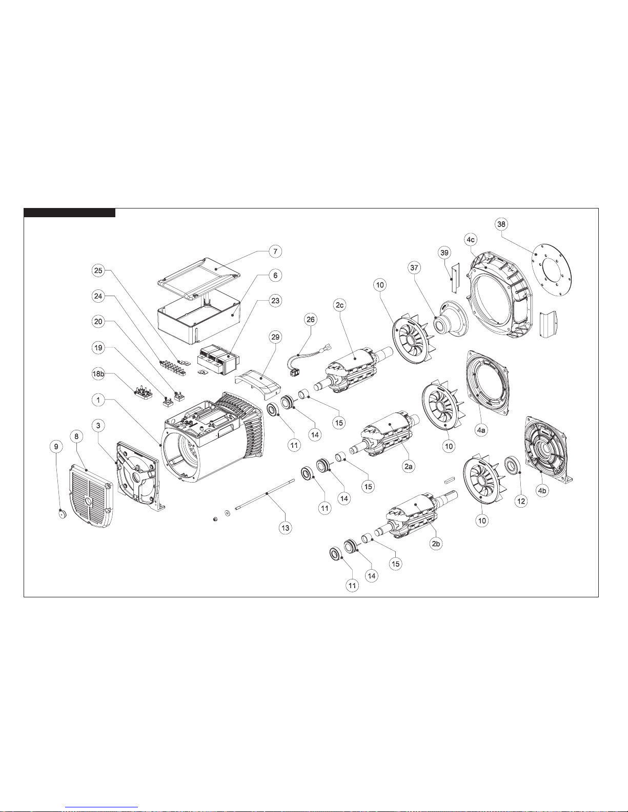
- 28 -
E1S11M

- 29 -
Nº COD. RICAMBI SPARE PARTS LISTA DE REPUESTOS PIECES DETACHEES ERSATZTEILE
1 * CARC. CON STATORE FRAME WITH STATOR CARC. CON ESTATOR CARCASSE AVEC STATOR GEHÄUSE MIT STATOR
2A * INDUTT. ROTAN. B9 B9 ROTAT. INDUCT. INDUCT. ROTAN. B9 ROUE POLAIRE B9 DREHANKER B9
2B * INDUTT. ROTAN. B14 B14 ROTAT. INDUCT. INDUCT. ROTAN. B14 ROUE POLAIRE B14 DREHANKER B14
2C * INDUTT. ROTAN. MD35 MD35 ROTAT. INDUCT. INDUCT. ROTAN. MD35 ROUE POLAIRE MD35 DREHANKER MD35
3 E11SE001A SCUDO POSTERIORE B3/B9 REAR SHIELD B3/B9 TAPA POSTERIOR B3/B9 FLASQUE ARRIERE B3/B9 HINTERER LAGERSCHILD B3/B9
4A * SCUDO ANTERIORE B9 FRONT COVER B9 TAPA ANTERIOR B9 FLASQUE AVANT B9 VORDERER LAGERSCHILD B9
4B E11SB001B SCUDO ANTERIORE B3/B14 FRONT COVER B3/B14 TAPA ANTERIOR B3/B14 FLASQUE AVANT B3/B14 VORDERER LAGERSCHILD B3/B14
4C * SCUDO ANTERIORE SAE SAE FRONT COVER TAPA ANTERIOR SAE FLASQUE AVANT SAE VORDERER LAGERSCHILD SAE
6 E10BT000C SCATOLA BASETTA TERMINAL BOX CAJA DE BORNES BOITE A BORNES KLEMMENKASTEN
7 E10BT001C COPRISCATOLA BASETTA TERMINAL BOX COVER TAPA CAJA DE BORNES COUVERCLE BOITE A BORNE DECKEL KLEMMENKASTEN
8 E11KA001C CUFFIA POSTERIORE REAR COVER PROTECCION POSTERIOR COIFFE DE PROTECTION ARRIERE HINTERE HAUBE
9 E11KA005A TAPPO POSTERIORE REAR PLUG TAPON BOUCHON POSTERIEUR HINTERER VERSCHLUSS
10 E11VE000B VENTOLA FAN VENTILADOR VENTILATEUR LÜFTER
11 EX411434325 CUSCINET TO POSTERIORE REAR BEARING COJINETE POSTERIOR ROULEMENT ARRIERE LAGER KUPPLUNGSGEGENSEITE (HINTEN)
12 EX411434335 CUSCINET TO ANTERIORE FRONT BEARING COJINETE ANTERIOR ROULEMENT AVANT LAGER KUPPLUNGSSEITE (VORNE)
13 * TIRANTE CENTRALE TIE ROD TIRANTE DE LA TAPA TIRANT CENTRAL MITTELSTANGE
13A * BUSSOLA PER TIRANTE CENTRALE BUSH THREADED CILINDRO ROSCADO DOUILLE POUR TIRANT CENTRAL BUCHSE FÜR MITTELSTANGE
14 E10KA000A COLLETTORE A 2 ANELLI SLIP RING ANILLOS COLECTORES COLLECTEUR A DEUX BAGUES KOLLEKTOR
15 E10KA015A BUSSOLA ISOLANTE ISOLATING BUSH ANILLO AISLADOR DOUILLE ISOLANTE ISOLIEREND BÜCHSE
18B EX561201005 MORSET TIERA PRINCIPALE A 6 PIOLI 6 STUD TERMINAL BOARD PLACA DE BORNES PRINCIPAL BORNIER A 6 BORNES 6-POLIGES KLEMMENBRETT
19 EX541805080 PONTE A DIODI MONOFASE SINGLE PHASE BRIDGE PUENTE RECTIFICADOR MONOFASICO PONT REDRESSEUR MONOPHASE EINPHASIGE-DIODENBRÜCKE
20 EX541802080 PONTE A DIODI TRIFASE THREE PHASE BRIDGE PUENTE RECTIFICADOR TRIFASICO PONT REDRESSEUR TRIPHASE DREIPHASEN-DIODENBRÜCKE
23 * COMPOUND COMPOUND COMPOUND COMPOUND KOMPOUND
24 E10KA011A MORSETTIERA AUSILIARIA AUXILIARY TERMINAL BOARD BORNERA AUXILIAR BORNIER AUXILIAIRE NEBEN-KLEMMENBRETT
25 E10KA014A SUPPORTI MORSETTIERA TERMINAL BOARD SUPPORTS SOPORTES DE BORNERA AUXILIAR SUPPORTS POUR BORNIER KLEMMENBRETT STUTZE
26 E10KA002A PORTASPAZZOLE COMPLETO BRUSH HOLDER PORTAESCOBILLAS COMPLETO PORTE-BALAIS COMPLET BÜRSTENHALTER
29 E11KA010C PROTEZIONE ANTERIORE IP21 IP 21 COVER PROTECCION ANTERIOR IP21 PROTECTION IP21 SCHUTZ IP 21
37 * MOZZO GIUNTO COUPLING HUB BRIDA MOYEU JOINT KUPPLUNGSNABE
38 * DISCO SAE COUPLING DISC PLATE DISCO SAE DISQUE SAE SCHEIBENKUPPLUNG SAE
39 E11KA006A PROTEZIONE SCUDO FRONT COVER PROTECTION PROTECCION TAPA ANTERIOR PROTECTION FLASQUE AVANT SCHUTZ FÜR ZUBEHÖR
* Specicare codice dell’alternatore e data di produzione - When requesting spare parts please indicate the alternator’s code and date of production - En cada pedido de piezas de repuestos especicar el código y la fecha de producción de la máquina - Pour
demander les pièces detachees, prière de mentionner le code et la date de production - Bei Ersatzteilbestellung bitte immer die Tellbenennung des Code und den Datum der Produktion des Wechselstromgenerators angeben
E1S11M

- 30 -
NOTE: .....................................................................................................................................................................................................................................................................................................................................................................................................
...............................................................................................................................................................................................................................................................................................................................................................................................................
...............................................................................................................................................................................................................................................................................................................................................................................................................
...............................................................................................................................................................................................................................................................................................................................................................................................................
...............................................................................................................................................................................................................................................................................................................................................................................................................
...............................................................................................................................................................................................................................................................................................................................................................................................................
...............................................................................................................................................................................................................................................................................................................................................................................................................
...............................................................................................................................................................................................................................................................................................................................................................................................................
...............................................................................................................................................................................................................................................................................................................................................................................................................
...............................................................................................................................................................................................................................................................................................................................................................................................................
...............................................................................................................................................................................................................................................................................................................................................................................................................
...............................................................................................................................................................................................................................................................................................................................................................................................................
...............................................................................................................................................................................................................................................................................................................................................................................................................
...............................................................................................................................................................................................................................................................................................................................................................................................................
...............................................................................................................................................................................................................................................................................................................................................................................................................
...............................................................................................................................................................................................................................................................................................................................................................................................................
...............................................................................................................................................................................................................................................................................................................................................................................................................
...............................................................................................................................................................................................................................................................................................................................................................................................................

- 31 -
NOTE: .....................................................................................................................................................................................................................................................................................................................................................................................................
...............................................................................................................................................................................................................................................................................................................................................................................................................
...............................................................................................................................................................................................................................................................................................................................................................................................................
...............................................................................................................................................................................................................................................................................................................................................................................................................
...............................................................................................................................................................................................................................................................................................................................................................................................................
...............................................................................................................................................................................................................................................................................................................................................................................................................
...............................................................................................................................................................................................................................................................................................................................................................................................................
...............................................................................................................................................................................................................................................................................................................................................................................................................
...............................................................................................................................................................................................................................................................................................................................................................................................................
...............................................................................................................................................................................................................................................................................................................................................................................................................
...............................................................................................................................................................................................................................................................................................................................................................................................................
...............................................................................................................................................................................................................................................................................................................................................................................................................
...............................................................................................................................................................................................................................................................................................................................................................................................................
...............................................................................................................................................................................................................................................................................................................................................................................................................
...............................................................................................................................................................................................................................................................................................................................................................................................................
...............................................................................................................................................................................................................................................................................................................................................................................................................
...............................................................................................................................................................................................................................................................................................................................................................................................................
...............................................................................................................................................................................................................................................................................................................................................................................................................

LINZ ELECTRIC Spa
Viale del Lavoro, 30 - 37040 Arcole (Vr) Italia
Tel. +39 045 7639201 - Fax +39 045 7639202
www.linzelectric.com - info@linzelectric.com
 Loading...