

Page 1
Page 1
WIRELESS MADE SIMPLE
Revised 7/15/04
INTRODUCTION
The Linx QS Series USB module allows the rapid addition of USB to virtually any
device.
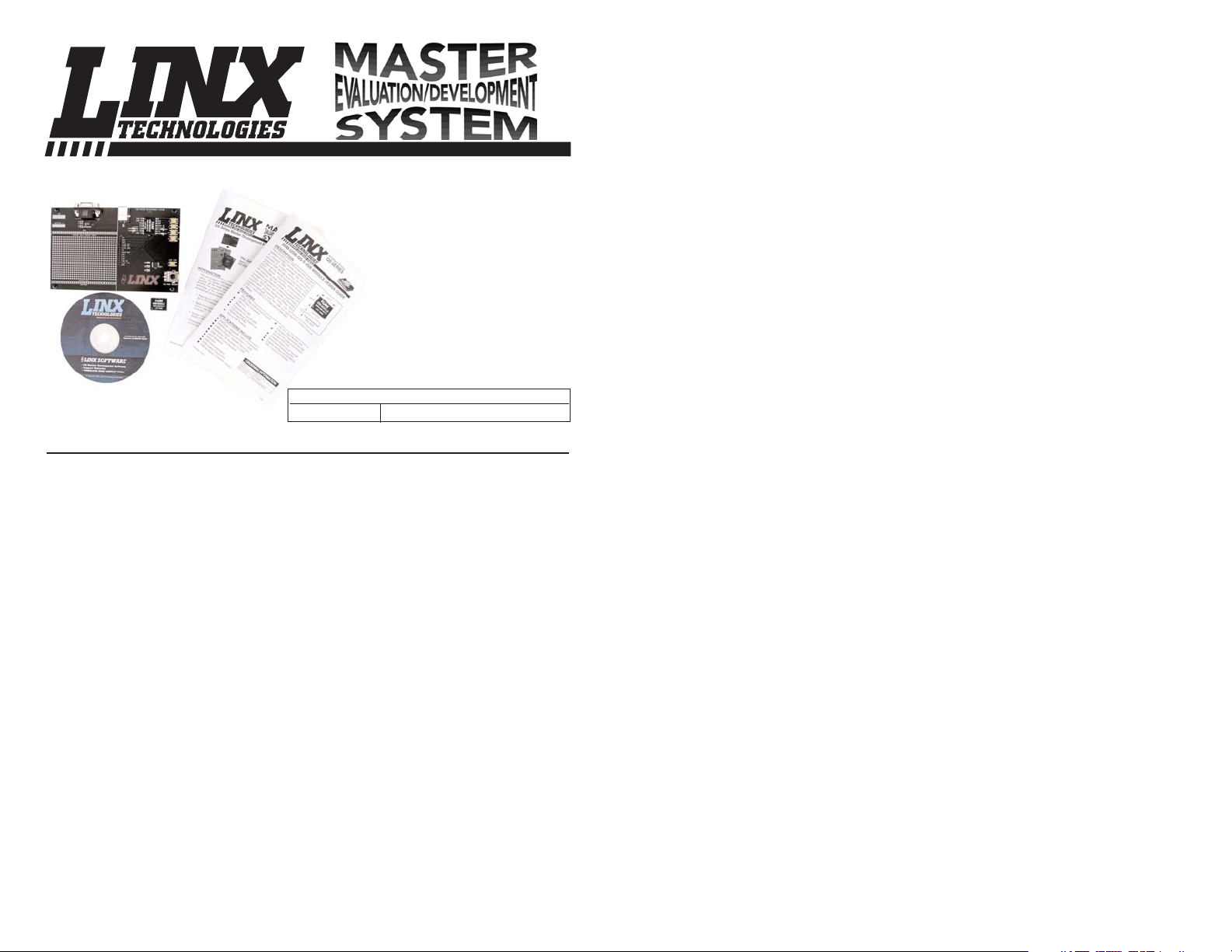
The master evaluation/development system is intended to give a
designer all the tools necessary to incorporate the module into an end product. The purpose of this guide is to show the designer how to take full advantage of the master development board included with the kit. The development
board serves several important functions:
•
Rapid Module Evaluation - The kit allows the module's performance to
be quickly evaluated.
•
Application Development - The kit comes with application software and
source code that demonstrate how to interface the module with the
computer.
•
Design - The kit shows how to design with the module and to physically
interface with other components.
•
Prototyping - The kit allows for additional circuitry to be placed directly
on the board so that it can act as the first prototype of the product.
QS Series Master Development System User’s Guide
This Guide Covers:
PART # DESCRIPTION
MDEV-USB-QS QS Series Master Development System
Page 2
Page 3Page 2
RF SECTION
SUPPLY
RELAY CHARACTERISTICS
RELAY FUNCTION MODULE FEATURES
THEORY OF OPERATION
The FCTN-RLYXXX-XXX module combines the popular Linx LC Series receiver with a decoder IC and four relays
which are capable of switching a variety
of AC or DC loads. The Relay Function
Module is designed to receive a wireless
signal transmitted from a compatible
Linx RF module or precertified OEM
transmitter. When transmitted data is
received, the data is presented to the
decoder. The decoder detects the logic
states of the DIP switch address lines. If
these match the address settings of the
encoder, the decoder’s outputs are set to
replicate the state of the encoder’s data
lines. The relay outputs are then latched
on or off. If momentary operation is
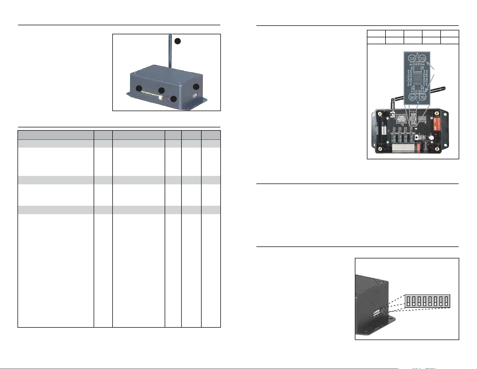
desired, jumper pads J2 through J5 can
be bridged. Figure 3 displays the location of the pads. Each jumper corresponds to a relay as shown.
POWER SUPPLY CONSIDERATIONS
It is important that the module be powered from a DC source that is free of noise
and high ripple. The best results are normally obtained using a battery or high
quality AC wall adapter capable of providing the supply currents indicated in the
specifications table. Two supply connection options are provided; black (ground)
and red (+) quick-connect terminals or a barrel jack (for a 5.5mm plug, tip 7 16VDC, shell ground). Only one connection should be used at a time and polarity should be observed.
SETTING MODULE ADDRESS
The Relay Function Module provides a total of 256 unique address
settings. Address selection is made
via eight externally accessible dip
switches. In order for the encoded
commands sent by the transmitter
to be recognized, the transmitter
and receiver’s address settings
must match precisely.
*Note* The relays will not switch
unless the address lines share
identical states with the transmitter’s encoder address lines.
1
2
5
4
3
SPECIFICATIONS
Figure 2: Key Locations
Figure 3: Jumper Pad Locations
A7 = 1
A6 = 2
A5 = 3
A4 = 4
A3 = 5
A2 = 6
A1 = 7
A0 = 8
OFF ON
Relay
1 2 3 4
Jumper
J2 J3 J5 J4
Figure 4: Address DIP Switches
NOTES:
1) Minimum specification is typical consumption without relays latched. Maximum is with all relays latched.
2) Model-dependent
PARAMETERS Min. Typ. Max. Units Notes
Supply Voltage 5.0 – 16 VDC
Current Requirement 12 – 170 mA 1
Operating temperature -30 – +70 °C
Storage temperature -45 – +85 °C
Receive Frequency – 315, 418, 433.92 – MHz 2
Receiver Sensitivity -92 -95 –
Noise BW – 280 – kHz
Arrangement SPST (1 Form A)
Max. Switched Power – – 150 Watts
– – 1250 VA
Relay Switching Voltage 0 – 30 VDC
0 – 250 VAC
Switched Device Current 0.6 – 5 Amps
Operate Time – 6 mS
Release Time – 3 mS
Life Expectancy
Mechanical 20 million Cycles
Electrical 1 x 10
-5
@ 5A
30VDC or 250VAC
Contact Dielectric Strength
(at sea level for 1 min.) 750 between open Vrms
3,000 contact-to-coil
Vrms
1) Antenna
2) DC Power Connector (5 - 16VDC)
3) "Quick-Connect" Alternate DC Input
4) Switched-Device Connectors
5) Address Selector Dip Switches
Jumper Pads
Page 3
Page 5Page 4
SWITCHED DEVICE ATTACHMENT
The Relay Function Module features heavy-duty quick-connect block terminals
for attaching the devices to be switched. The terminals accept wire gages from
16-26 AWG. Funnel-shaped entry channels help prevent fraying when using
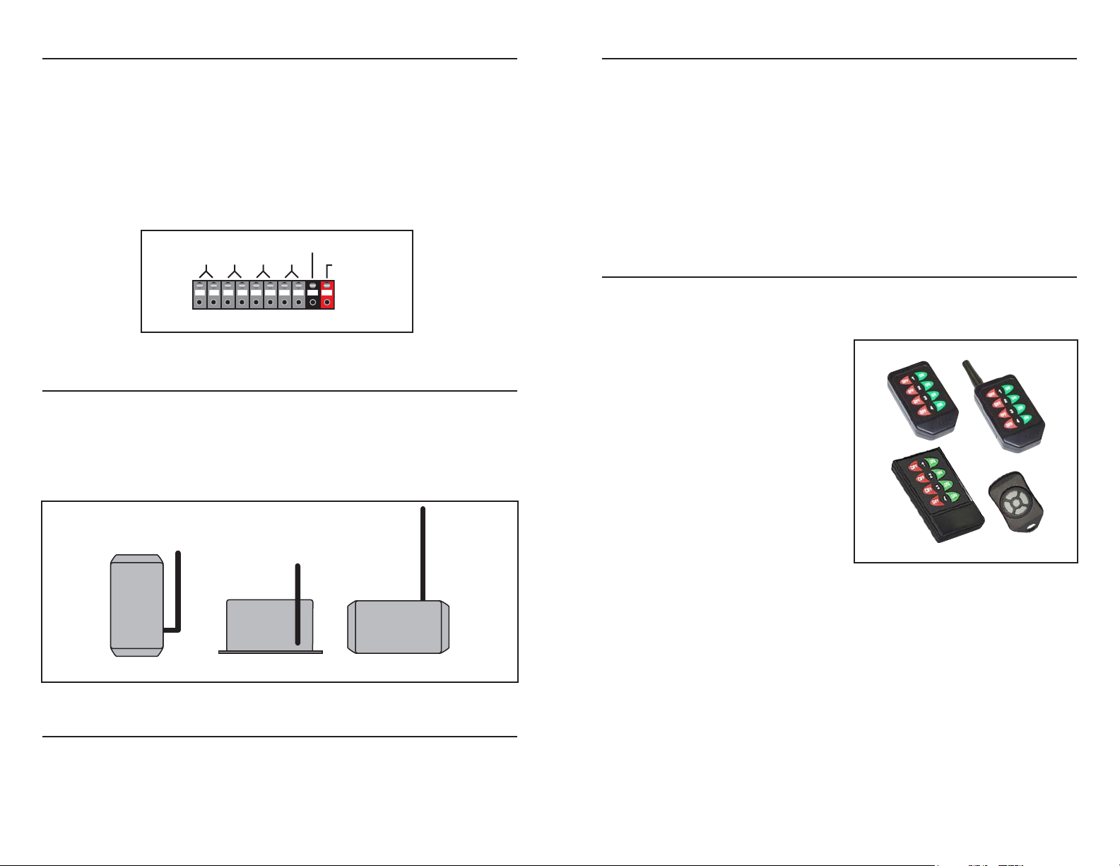
untinned wire. The terminal block is arranged as shown. There is no polarity on
the relay terminals and they may be used in any order or left unterminated without internal damage. Do not attempt to switch loads in excess of the limits listed
in the Specifications section. The module does not provide internal protection for
shorted loads. The designer must, therefore, provide external protection, such as
fusing, if the possibility of shorting exists.
ANTENNA ORIENTATION
It is always important to remember that the control signals for the Relay Function
Module are sent through the air. For this reason the physical orientation of the
transmitter and receiver plays an important role in determining the overall range.
The antenna may be swiveled to adjust for maximum range in your environment.
In most cases, orienting the antennas in a vertical position will result in optimum
performance.
CONTENTION CONSIDERATIONS
An unlimited number of Relay Function Modules may be operated in proximity
without interference. It is important, however, to understand that only one transmitter at a time can be activated within a reception area. While the transmitted
signal consists of encoded digital data, only one carrier of any frequency can
occupy airspace without contention at any given time.
Poor Optimum Acceptable
Figure 6: Antenna Orientation
INTERFERENCE CONSIDERATIONS
It is important to remember that the range performance of the modules is heavily dependent on the environment in which they are operated. The effects of interference, multipath, and physical attenuation will vary significantly from location to
location.
The Relay Function Module is based on the Linx LC Series of RF modules.
These are simple low-cost devices intended for short-range transmissions. They
utilize OOK AM-based modulation. AM devices can be affected by external noise
such as that from motors or other sources of broadband RF emissions.
Interference can also come from sources such as paging towers or amateur
radio activity. The designer should carefully test the Relay Function Module in
the environment in which it will be used to ensure that its performance is appropriate for the chosen application.
TRANSMITTER CONSIDERATIONS
The Relay Function Module incorporates a Linx LC Series receiver paired with a
Holtek decoder IC. This means that there are several options available for controlling the module.
The first option is to use one of the precertified OEM transmitters offered by
Linx. These transmitters come in several packages and can be customized to
bear the logo or other artwork required
by the customer. The only setup
required by the customer is to set the
address of the transmitter and the
Relay module.
There are four OEM transmitters that
can be used with the Relay Function
Module: the full size handheld, the
compact handheld, the long-range
handheld, and the keyfob. The full size
handheld uses the same eight address
lines used by the Relay Function
Module, so they only need to be set the
same for proper function.
The other three transmitters use all ten address lines offered by the Holtek ICs
while the Relay Function Module uses eight. This means that the last two
address lines on the transmitters (A8 and A9) must be left floating (turn off the
DIP switches on the handhelds, cut traces 8 and 9 on the keyfob). The other
address lines can be set to whatever the user desires, as long as the transmitter
and the Relay Function Module match.
A custom transmitter can also be created with a KH, LC, or LR Series transmitter paired with a Holtek encoder or microprocessor. Because the Holtek ICs have
10 address lines, the last two lines (A8 and A9) must be left open. The Holtek
address lines are tri-state, meaning that they have three valid input conditions:
high, low, or floating. The Relay Function Module uses only the low and floating
states, so the custom transmitter can only use these states as well. The lines that
are floating should be left open and have no electrical connection.
RELAYS
1234
GND
5 - 16VDC
Figure 5: Relay Connection Block
Figure 7: Precertified Transmitters
Page 4
Page 7Page 6
FCC COMPLIANCE REQUIREMENTS
The FCTN-RLYXXX-XXX has been tested by an FCC-approved facility and
found to comply will all applicable FCC requirements as of the date of this document. A declaration of conformity (DOC) is on file. It is the user’s responsibility
to consult the FCC or other testing body to determine what additional testing may
be required on the user’s completed product. In products where no additional
testing is required, further labeling of the unit is not needed unless the module
will be placed inside another housing. It is, however, necessary to include the
following statement in the end product’s instruction manual or insert card.
INSTRUCTION TO THE USER
This equipment has been tested and found to comply with the limits for a Class B digital device, pursuant to Part 15 of the FCC
Rules. These limits are designed to provide reasonable protection
against harmful interference in a residential installation. This
equipment generates, uses and can radiate radio frequency energy and, if not installed and used in accordance with the instructions, may cause harmful interference to radio communications.
However, there is no guarantee that interference will not occur in
a particular installation. If this equipment does cause harmful interference to radio or television reception, which can be determined
by turning the equipment off and on, the user is encouraged to try
to correct the interference by one or more of the following measures:
Reorient or relocate the receiving antenna.
Increase the separation between the equipment and receiver.
Connect the equipment into an outlet on a circuit different from that
to which the receiver is connected.
Consult the dealer or an experienced radio/TV technician for help.
This equipment has been certified to comply with the limits for a
Class-B computing device, pursuant to FCC Rules. In order to
maintain compliance with FCC regulations, shielded cables must
be used with this equipment. Operation with non-approved equipment or unshielded cables is likely to result in interference to radio
and TV reception. The user is cautioned that changes and modifications made to the equipment without the approval of manufacturer could void the user's authority to operate this equipment.
TRANSMITTER ADDRESS SETTINGS
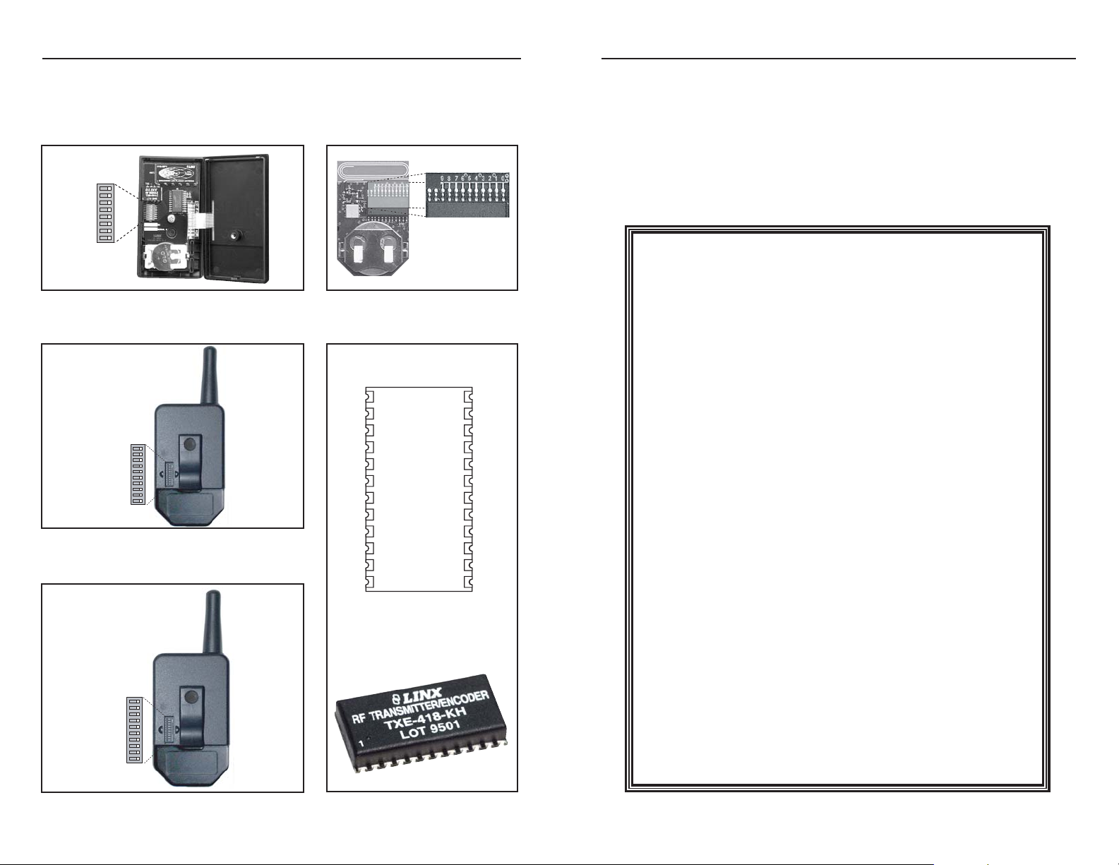
The Relay Function Module and the corresponding transmitter must have the
same address setting in order to function together. The following figures show
how to set the address on the Linx transmitters described in the previous section.
Figure 8: Full Size Handheld Transmitter Figure 9: Keyfob Transmitter
Figure 10: Compact Handheld Transmitter
Figure 11: Long Range Handheld Transmitter
Figure 12: KH Series Transmitter
ON OFF
A0 = 8
A1 = 7
A2 = 6
A3 = 5
A4 = 4
A5 = 3
A6 = 2
A7 = 1
TOP VIEW
OFF ON
A0 = 1
A1 = 2
A2 = 3
A3 = 4
A4 = 5
A5 = 6
A6 = 7
A7 = 8
A8 = 9
A9 = 10
GND/LVL
1
D0
2
D1
3
GND
4
VCC
5
TE
6
D2
7
D3
8
D4 A3
D5 A2
D6 A1
D7 A0
ANT
GND
A9
A8
A7
A6
A5
A4
24
23
22
21
20
19
18
17
169
1510
1411
1312
OFF ON
A0 = 1
A1 = 2
A2 = 3
A3 = 4
A4 = 5
A5 = 6
A6 = 7
A7 = 8
A8 = 9
A9 = 10
Page 5
Page 9Page 8
LABELING WHEN MODULE IS ENCASED
In cases where the FCTN-RLYXXX-XXX module is incorporated inside an OEM
product and its standard labeling is not visible, the end product must be labeled
as shown below.
• The following label shall be affixed in a conspicuous location to any device
previously self-certified under the FCC's Declaration of Conformity process,
when the product is authorized based on assembly using separately authorized components and the resulting product does not require additional testing:
• When the device is constructed in two or more sections connected by wires
and marketed together, the label is required to be affixed only to the main control unit.
• When the device is so small or for such use that it is not practical to place the
statement on the unit itself, the information shown on the label shall be placed
in a prominent location in the instruction manual or pamphlet supplied to the
user or, alternatively, shall be placed on the container in which the device is
marketed. However, the unique FCC logo, device trade name, and model
number must be present on the device.
• The label shall not be a stick-on paper label. The label shall be "permanently
affixed" to the device (meaning the label is etched, engraved, stamped, silkscreened, indelibly printed on a permanently attached part of the device or on
a nameplate fastened to the equipment by welding, riveting, or a permanent
adhesive). The label must be designed to last the expected lifetime of the
equipment in the environment in which the equipment may be operated and
may not be readily detachable.
Your Company Name Your Product
Name/ID#
Assembled From
Tested Components
(Complete System Not Tested)
FOR HOME OR OFFICE USE
ON-LINE RESOURCES
• Latest News
• Data Guides
• Application Notes
• Knowledge Base
• Software Updates
If you have questions regarding any Linx product and have Internet access,
make www.linxtechnologies.com your first stop. Our website is organized in an
intuitive format to give you the answers you need in record time. Day or night,
the Linx website gives you instant access to the latest information regarding the
products and services of Linx. It's all here: manual and software updates,
application notes, a comprehensive knowledge base, FCC information and much
more. Be sure to visit often!
www.antennafactor.com
The Antenna Factor division of Linx offers
a diverse array of antenna styles, many of
which are optimized for use with our RF
modules. From innovative embeddable
antennas to low-cost whips, domes to
yagi's, and even GPS, Antenna Factor
likely offers or can design an antenna to
meet your requirements.
www.connectorcity.com
Through its Connector City division, Linx offers a wide
selection of high-quality RF connectors, including FCCcompliant types such as RP-SMAs that are an ideal
match for our modules and antennas. Connector City
focuses on high-volume OEM requirements, which
allows standard and custom RF connectors to be offered
at a remarkably low cost.
www.linxtechnologies.com
WIRELESS MADE SIMPLE
Page 6
Page 11Page 10 Page 11Page 10
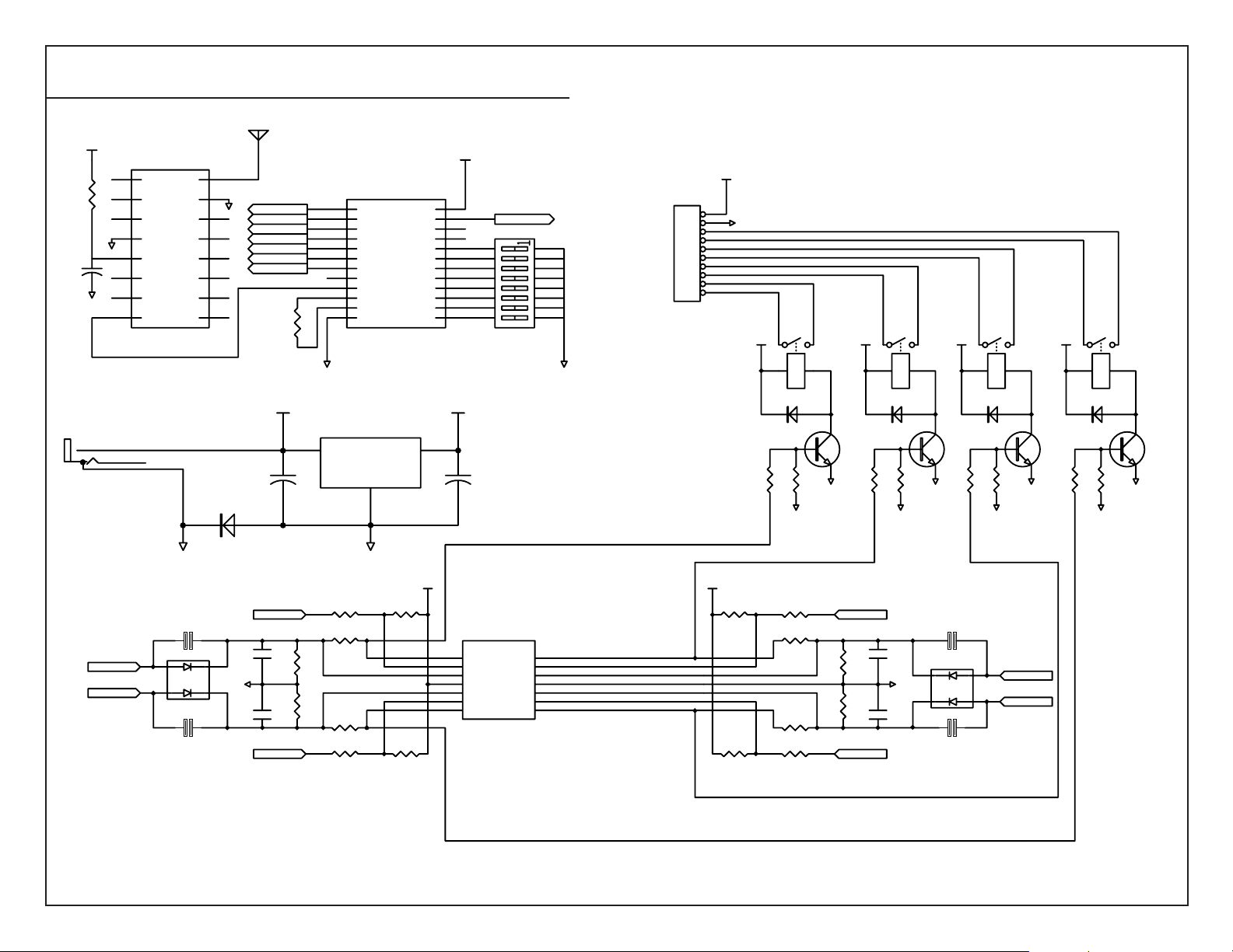
LINX FCTN-RLY4-XXX
1-4 POSITION RELAY FUNCTION MODULE SCHEMATIC
ANT1
ANTENNA
R10
100 ohm
C4
.01uF
VCC
1
2
3
4
GND
5
6
7
GND
8 9
RX1
NC
NC
NC
GND
VCC
PDN
NC
DATA NC
RX-LC-LR-S
ANT
GND
NC
NC
NC
NC
NC
16
15
RESET RE4
GND
14
SET RE3
RESET RE3
13
SET RE2
RESET RE2
12
SET RE1
RESET RE1
11
10
R7
390K
U1
HT_658
1
D1
2
D2
3
D3
4
D4
5
D5
6
D6
7
D7
8
VT
9
DIN
10
OSC1
11
OSC2
12 13
GND A0
GND
VCC
D0
A9
A8
A7
A6
A5
A4
A3
A2
A1
VCC
24
23
22
21
20
19
18
17
16
15
14
SET RE4
S1
1
2
3
4
5
6
7
8
VCC12
JP1
1
V-
2
3
16
15
14
13
12
11
10
9
GND
4
5
6
7
8
9
10
VCC
VCC
RE1 RE2 RE3
VCC
VCC
RE4
J1
PWRJACK
V+
SW V-
V-
SET RE1
SET RE4
V-
U2
4
DPAK-X2
D5
1N4001
J2
JUMPER-SMT
23
1
J4
JUMPER-SMT
GND
C1
1000uF
VCC12
RESET RE1
C3
.1uF
C5
.1uF
RESET RE4
U5
LDO VREG
1
Vin Vout
++
R11
560K
R12
560K
R15
100K
R23
270K
R24
270K
R19
100K
GND
2
GND
R16
100K
R20
100K
VCC
VCC
3
U4
1
2
3
4
5
6
7
LMV324
C2
10uF
OUTA
OUTD
INAINA+
VCC
INB+
INBOUTB OUTC
INDIND+
GND
INC+
INC-
14
13
12
11
10
9
8
VCC
R17
100K
R21
100K
R1
2.2K
D1
4148
R18
100K
R25
270K
R26
270K
R22
100K
R4
10K
GND
Q1
2N2222
RESET RE2
R13
560K
R14
560K
RESET RE3
D2
4148
R2
R5
10K
2.2K
GND
GND GNDGND
C6
.1uF
U3
1
GND
23
C7
DPAK-X2
.1uF
D3 D4
4148 4148
Q2
2N2222
R3
R6
2.2K
10K
J3
JUMPER-SMT
4
SET RE2
SET RE3
J5
JUMPER-SMT
GND
Q3
2N2222
R8
2.2K
GND
R9
10K
GND
Q4
2N2222
Page 7

Page 12Page 12
Linx Technologies is continually striving to improve the quality and function of its products; for
this reason, we reserve the right to make changes without notice. The information contained in
this Data Sheet is believed to be accurate as of the time of publication. Specifications are based
on representative lot samples. Values may vary from lot to lot and are not guaranteed. Linx
Technologies makes no guarantee, warranty, or representation regarding the suitability or legality of any product for use in a specific application. None of these devices is intended for use in
applications of a critical nature where the safety of life or property is at risk. The user assumes
full liability for the use of product in such applications. Under no conditions will Linx
Technologies be responsible for losses arising from the use or failure of the device in any application, other than the repair, replacement, or refund limited to the original product purchase
price. Some devices described in this publication are patented. Under no circumstances shall
any user be conveyed any license or right to the use or ownership of these patents.
Disclaimer
© 2003 by Linx Technologies, Inc. The stylized
Linx logo, Linx, and “Wireless Made Simple”
are the trademarks of Linx Technologies, Inc.
Printed in U.S.A.
LINX TECHNOLOGIES, INC.
575 S.E. ASHLEY PLACE
GRANTS PASS, OR 97526
Phone: (541) 471-6256
FAX: (541) 471-6251
http://www.linxtechnologies.com
U.S. CORPORATE HEADQUARTERS:
WIRELESS MADE SIMPLE
 Loading...