

Page 1

EVM-868-EUR
Data Guide
Page 2

Page 3

Table of Contents
1
Description
2
Ordering Information
2
Electrical Specications
4
Pin Assignments
5
Pin Descriptions
6
PCB Footprint
7
Schematic Diagram
8
Common Antenna Styles
10
Regulatory Considerations
12
Achieving a Successful RF Implementation
13
Helpful Application Notes from Linx
15
Resources
Page 4

Warning: Linx radio frequency (“RF”) products may be
!
used to control machinery or devices remotely, including machinery
or devices that can cause death, bodily injuries, and/or property
damage if improperly or inadvertently triggered, particularly in industrial
settings or other applications implicating life-safety concerns. No Linx
Technologies product is intended for use in any application without
redundancies where the safety of life or property is at risk.
The customers and users of devices and machinery controlled with
RF products must understand and must use all appropriate safety
procedures in connection with the devices, including without limitation,
using appropriate safety procedures to prevent inadvertent triggering
by the user of the device and using appropriate security codes to
prevent triggering of the remote controlled machine or device by users
of other remote controllers.
Do not use this or any Linx product to trigger an action directly
from the data line or RSSI lines without a protocol or encoder/
decoder to validate the data. Without validation, any signal from
another unrelated transmitter in the environment received by the
module could inadvertently trigger the action. This module does not
have data validation built in.
All RF products are susceptible to RF interference that can
prevent communication. RF products without frequency agility or
hopping implemented are more subject to interference. This module
does not have frequency agility built in, but the developer can
implement frequency agility with a microcontroller and the example
code in Linx Reference Guide RG-00101.
Do not use any Linx product over the limits in this data guide.
Excessive voltage or extended operation at the maximum voltage
could cause product failure. Exceeding the reflow temperature profile
could cause product failure which is not immediately evident.
Do not make any physical or electrical modifications to any
Linx product. This will void the warranty and regulatory and UL
certifications and may cause product failure which is not immediately
evident.
Page 5
EVM-868-EUR
Data Guide
Description
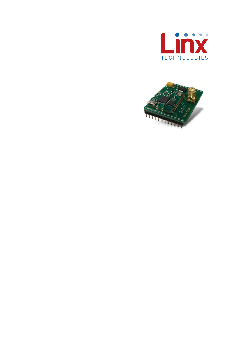
The EVM-868-EUR combines the
TRM-868-EUR transceiver module with
an SMA antenna connector and voltage
regulator on a DIP board. This simplifies
integration of the module into prototype
and low volume designs.
The module combines a state-of-the art low
power wireless transceiver with a powerful multipoint-to-multipoint protocol
controller to form a transparent wireless communication solution capable of
replacing wires in almost any RS-232/422/485 application. With a 112dB
link budget and very low power operation modes, the TRM-868-EUR
module is excellent for AMR, RFID, Home Automation, and any other
application requiring long range (<1500ft. , line of sight) and long battery
life.
The module is designed to be totally transparent. No special addressing
or formatting of data is required. Data is validated using an internally
generated CRC-16 and encoded using a proprietary algorithm. Multiple
modules can operate on the same channel because of the built-in carriersense-multiple-access (CSMA) protocol.
Figure 1: EVM-868-EUR Module
Features
• 13dBm output power
• 112dBm link budget
• 38.4kbps data rate
• Wideband and narrowband
operation
• 25mA RX, 60mA TX @ 13dBm
Applications Include
• Automatic Meter Reading
• Wireless Sensing
• Industrial Controls
• Home / Industrial Automation
• Remote Status Monitoring
• Lighting Control
– –
1
11/20/12
Page 6

Ordering Information
Ordering Information
Product Part No. Description Radiotronix Part No.
EVM-868-EUR-RA
EVM-868-EUR-ST
Figure 2: Ordering Information
TRM-868-EUR Evaluation Module,
868MHz, Right Angle RP-SMA Connector
TRM-868-EUR Evaluation Module,
868MHz, Straight RP-SMA Connector
Wi.232EUR-EVM-R
Electrical Specications
Electrical Specifications
Parameter Designation Min. Typ. Max. Units Notes
Power Supply
Operating Voltage V
Supply Current I
CC
CC
Receive 25 mA
Transmit, Po = 0dBm 35 mA
Transmit, Po = 13dBm 60 mA
Digital Interface
Output
Logic Low V
Logic High V
OL
OH
Input
Logic Low V
Logic High V
IL
IH
Environmental
Operating Temperature Range –40 85 °C
4 12 VDC
0 0.4 VDC
2.5 V
CC
0 0.3*VCCVDC
0.7*V
CC
V
CC
VDC
VDC
Figure 3: Electrical Specifications
Please see the TRM-868-EUR data guide for additional specifications and
operational details.
– –
2
Page 7
Pin Assignments
1
2
3
4
5
6
7
8
9
10
11
12
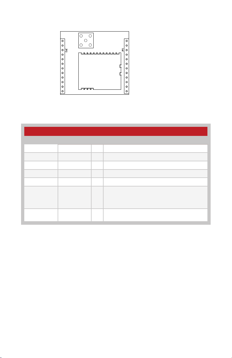
Figure 4: EVM-868-EUR Pin Assignments
Pin Descriptions
Pin Descriptions
Pin Number Name I/O Description
1 V
CC
2 RXD0 I Serial Port Receive Data
3 TXD0 O Serial Port Transmit Data
4 CTS0 O Serial Port Clear To Send
5 COMMAND Command
6, 7, 8, 9, 10,
15, 16, 17,
18, 19, 20,
N/C No Electrical Connection
21, 22
11, 12, 13,
14, 23, 24
GND Analog Ground
4V to 12V Supply Voltage
24
23
22
21
20
19
18
17
16
15
14
13
Figure 5: Pin Descriptions
– –
3
Page 8
PCB Footprint
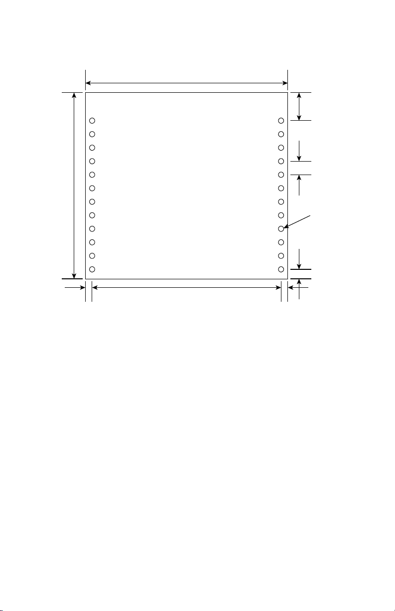
1 24
1.38”
(35.05)
0.05”
(1.27)
1.50”
(38.10)
1.40”
(35.56)
0.208”
(5.28)
0.10”
(2.54)
Ø0.04” x 24
(1.02)
0.07”
(1.78)
0.05”
(1.27)
Figure 6: EVM-868-EUR PCB Footprint
– –
4
Page 9
Schematic Diagram
GND
DTR1
*DTR1PD1
TXD1
RTS1
RTS0
RXD1
TXD0
CTS0
RXD0
VIN
C2
CAP0805-4.7UF
GND
VCCVCC
JP2
JP1
RES0603-1K
R2
RES0603-1K
R1
101112
PD2
JP3
VCC
PD3
PD4EXRSSI
123
CMD_RSP
BE
4
CON-SKT1X4
GND
123456789
CON-HDR1X12
23456789101112
CON-HDR1X12
J1
14 1
U1
IC-39100-3.3BS
GND
CON-SMAPCB
CMD_RSP
RSSI
VCC
GND
CTS0
3
OUT
IN
1
VIN
TXD0
RXD0
CA-T47U6-01
C1
+
GND
GND
BE
RTS0
345678910111213
T
2
3.3V
GND
GNDGND
GNDGNDGND
VCC
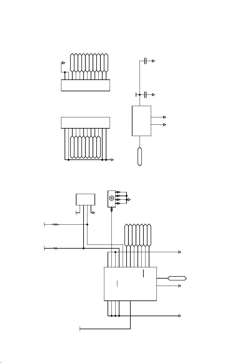
Figure 7: EVM-868-EUR Schematic
MOD1
15
C2D
ANT
GND
GNDGND
RST / C2CK
GND16GND17GND18VCC
– –
5
NC
NC
19
CTS
TxD
RxD
CMD
NC
NC
GND
2
1
EX
Page 10
Common Antenna Styles
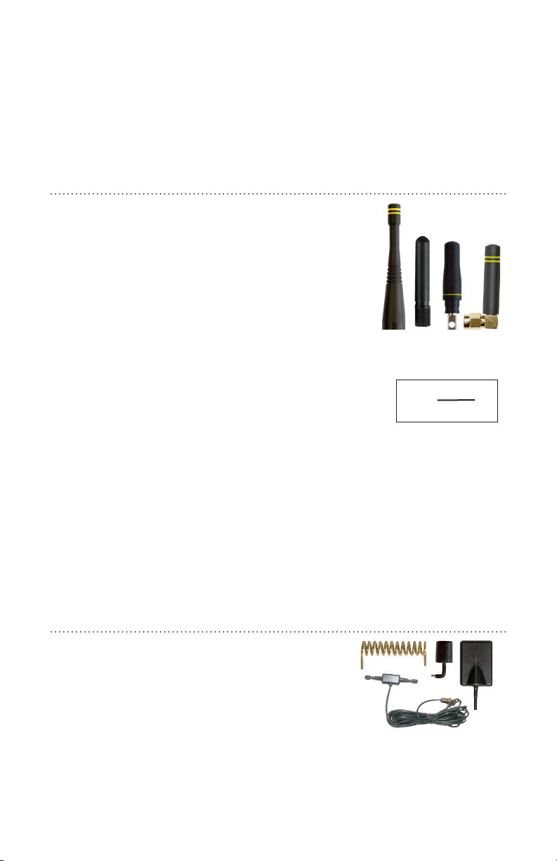
There are hundreds of antenna styles and variations that can be employed
with Linx RF modules. Following is a brief discussion of the styles most
commonly utilized. Additional antenna information can be found in Linx
Application Notes AN-00100, AN-00140, AN-00500 and AN-00501 (Figure
14).
Whip Style
A whip style antenna (Figure 8) provides
outstanding overall performance and stability.
A low-cost whip is can be easily fabricated from
a wire or rod, but most designers opt for the
consistent performance and cosmetic appeal of a
professionally-made model. To meet this need, Linx
offers a wide variety of straight and reduced height
whip style antennas in permanent and
connectorized mounting styles.
Figure 8: Whip Style Antennas
The wavelength of the operational frequency
determines an antenna’s overall length. Since a
L =
234
F
MHz
full wavelength is often quite long, a partial half or
quarter-wave antenna is normally employed. Its size and
natural radiation resistance make it well matched to
Linx modules. The proper length for a straight
quarter-wave can be easily determined using the formula
Figure 9:
L = length in feet of
quarter-wave length
F = operating frequency
in megahertz
in Figure 9. It is also possible to reduce the overall height of the antenna by
using a helical winding. This reduces the antenna’s bandwidth but is a great
way to minimize the antenna’s physical size for compact applications. This
also means that the physical appearance is not always an indicator of the
antenna’s frequency.
Specialty Styles
Linx offers a wide variety of specialized antenna
styles (Figure 10). Many of these styles utilize
helical elements to reduce the overall antenna size
while maintaining reasonable performance.
A helical antenna’s bandwidth is often quite
narrow and the antenna can detune in
proximity to other objects, so care must be
Figure 10: Specialty Style Antennas
exercised in layout and placement.
– –
6
Page 11

Loop Style
A loop or trace style antenna is normally printed
directly on a product’s PCB (Figure 11). This makes
it the most cost-effective of antenna styles. The
element can be made self-resonant or externally
resonated with discrete components, but its actual
layout is usually product specific. Despite the cost
advantages, loop style antennas are generally
Figure 11: Loop or Trace Antenna
inefficient and useful only for short range
applications. They are also very sensitive to
changes in layout and PCB dielectric, which can
cause consistency issues during production.
In addition, printed styles are difficult to engineer,
requiring the use of expensive equipment including
a network analyzer. An improperly designed loop
Figure 12: SP Series
“Splatch” Antenna
will have a high SWR at the desired frequency
which can cause instability in the RF stage.
Linx offers low-cost planar and chip (Figure 12) antennas that mount
directly to a product’s PCB. These tiny antennas do not require testing
and provide excellent performance in light of their small size. They offer a
preferable alternative to the often problematic “printed” antenna.
– –
7
Page 12

Regulatory Considerations
Note: Linx RF modules are designed as component devices that
require external components to function. The modules are intended to
allow for full Part 15 compliance; however, they are not approved by
the FCC or any other agency worldwide. The purchaser understands
that approvals may be required prior to the sale or operation of the
device, and agrees to utilize the component in keeping with all laws
governing its use in the country of operation.
When working with RF, a clear distinction must be made between what is
technically possible and what is legally acceptable in the country where
operation is intended. Many manufacturers have avoided incorporating RF
into their products as a result of uncertainty and even fear of the approval
and certification process. Here at Linx, our desire is not only to expedite the
design process, but also to assist you in achieving a clear idea of what is
involved in obtaining the necessary approvals to legally market your
completed product.
For information about regulatory approval, read AN-00142 on the Linx
website or call Linx. Linx designs products with worldwide regulatory
approval in mind.
In the United States, the approval process is actually quite straightforward.
The regulations governing RF devices and the enforcement of them are
the responsibility of the Federal Communications Commission (FCC). The
regulations are contained in Title 47 of the United States Code of Federal
Regulations (CFR). Title 47 is made up of numerous volumes; however,
all regulations applicable to this module are contained in Volume 0-19.
It is strongly recommended that a copy be obtained from the
Government Printing Office in Washington or from your local government
bookstore. Excerpts of applicable sections are included with Linx
evaluation kits or may be obtained from the Linx Technologies website,
www.linxtechnologies.com. In brief, these rules require that any device
that intentionally radiates RF energy be approved, that is, tested for
compliance and issued a unique identification number. This is a relatively
painless process. Linx offers full EMC pre-compliance testing in our
HP/Emco-equipped test center. Final compliance testing is then performed
by one of the many independent testing laboratories across the country.
Many labs can also provide other certifications that the product may require
at the same time, such as UL, CLASS A/B, etc.
– –
8
Page 13

Once your completed product has passed, you will be issued an ID number
that is to be clearly placed on each product manufactured.
Questions regarding interpretations of the Part 2 and Part 15 rules or
measurement procedures used to test intentional radiators such as Linx RF
modules for compliance with the technical standards of Part 15 should be
addressed to:
Federal Communications Commission
Equipment Authorization Division
Customer Service Branch, MS 1300F2
7435 Oakland Mills Road
Columbia, MD, US 21046
Phone: +1 301 725 585 | Fax: +1 301 344 2050
Email: [email protected]
ETSI Secretaria
650, Route des Lucioles
06921 Sophia-Antipolis Cedex
France
Phone: +33 (0)4 92 94 42 00
Fax: +33 (0)4 93 65 47 16
International approvals are slightly more complex, although Linx
modules are designed to allow all international standards to be met. If you
are considering the export of your product abroad, you should contact Linx
Technologies to determine the specific suitability of the module to your
application.
All Linx modules are designed with the approval process in mind and thus
much of the frustration that is typically experienced with a discrete design
is eliminated. Approval is still dependent on many factors, such as the
choice of antennas, correct use of the frequency selected and physical
packaging. While some extra cost and design effort are required to address
these issues, the additional usefulness and profitability added to a product
by RF makes the effort more than worthwhile.
– –
9
Page 14
Achieving a Successful RF Implementation
Adding an RF stage brings an exciting new
dimension to any product. It also means that
additional effort and commitment will be
needed to bring the product successfully to
market. By utilizing pre-made RF modules the
design and approval process is greatly
simplified. It is still important, however, to have
an objective view of the steps necessary to
ensure a successful RF integration. Since the
capabilities of each customer vary widely, it is
difficult to recommend one particular design
path, but most projects follow steps similar to
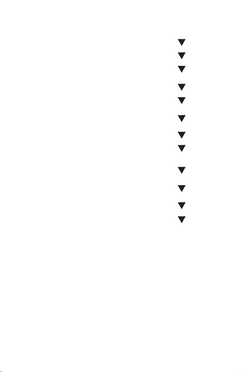
those shown in Figure 13.
ORDER EVALUATION KIT(S)
CONSULT LINX REGARDING
ANTENNA OPTIONS AND DESIGN
DECIDE TO UTILIZE RF
RESEARCH RF OPTIONS
TEST MODULE(S) WITH
BASIC HOOKUP
CHOOSE LINX MODULE
INTERFACE TO CHOSEN
CIRCUIT AND DEBUG
In reviewing this sample design path, you may
notice that Linx offers a variety of services
(such as antenna design and FCC prequalification) that are unusual for a high-volume
component manufacturer. These services,
along with an exceptional level of technical
support, are offered because we recognize
that RF is a complex science requiring the
highest caliber of products and support.
Wireless made simple is more than just a
motto: it’s our commitment. By choosing Linx
as your RF partner and taking advantage of
the resources we offer, you will not only survive
implementing RF, you may even find the
process enjoyable.
LAY OUT BOARD
SEND PRODUCTION-READY
PROTOTYPE TO LINX
FOR EMC PRESCREENING
OPTIMIZE USING RF SUMMARY
GENERATED BY LINX
SEND TO PART 15
TEST FACILITY
RECEIVE FCC ID #
COMMENCE SELLING PRODUCT
Figure 13: Typical Steps for Implementing
RF
– –
10
Page 15
Resources
Support
For technical support, product documentation, application notes, regulatory
guidelines and software updates, visit www.linxtechnologies.com
RF Design Services
For customers who need help implementing Linx modules, Linx offers
design services including board layout assistance, programming,
certification advice and packaging design. For more complex RF solutions,
Apex Wireless, a division of Linx Technologies, creates optimized designs
with RF components and firmware selected for the customer’s application.
Call +1 800 736 6677 (+1 541 471 6256 if outside the United States) for
more information.
Antenna Factor Antennas
Linx’s Antenna Factor division has the
industry’s broadest selection of antennas
for a wide variety of applications.
For customers with specialized needs,
custom antennas and design services are available along with simulations
of antenna performance to speed development. Learn more at
www.linxtechnologies.com,
Helpful Application Notes from Linx
It is not the intention of this manual to address in depth many of the issues
that should be considered to ensure that the modules function correctly
and deliver the maximum possible performance. As you proceed with your
design, you may wish to obtain one or more of the following application
notes which address in depth key areas of RF design and application of
Linx products. These application notes are available online at
www.linxtechnologies.com or by contacting Linx.
by
Helpful Application Note Titles
Note Number Note Title
AN-00100 RF 101: Information for the RF Challenged
AN-00130 Modulation Techniques for Low-Cost RF Data Links
AN-00160 Considerations for Sending Data Over a Wireless Link
AN-00500 Antennas: Design, Application, Performance
AN-00501 Understanding Antenna Specifications and Operation
Figure 14: Helpful Application Notes
– –
11
Page 16

Linx Technologies
159 Ort Lane
Merlin, OR, US 97532
3090 Sterling Circle, Suite 200
Boulder, CO 80301
Phone: +1 541 471 6256
Fax: +1 541 471 6251
www.linxtechnologies.com
Disclaimer
Linx Technologies is continually striving to improve the quality and function of its products. For this reason, we
reserve the right to make changes to our products without notice. The information contained in this Data Guide
is believed to be accurate as of the time of publication. Specifications are based on representative lot samples.
Values may vary from lot-to-lot and are not guaranteed. “Typical” parameters can and do vary over lots and
application. Linx Technologies makes no guarantee, warranty, or representation regarding the suitability of any
product for use in any specific application. It is Customer’s responsibility to verify the suitability of the part for the
intended application. At Customer’s request, Linx Technologies may provide advice and assistance in designing
systems and remote control devices that employ Linx Technologies RF products, but responsibility for the ultimate
design and use of any such systems and devices remains entirely with Customer and/or user of the RF products.
LINX TECHNOLOGIES DISCLAIMS ANY AND ALL WARRANTIES OF MERCHANTABILITY AND FITNESS FOR A
PARTICULAR PURPOSE. IN NO EVENT SHALL LINX TECHNOLOGIES BE LIABLE FOR ANY CUSTOMER’S OR
USER’S INCIDENTAL OR CONSEQUENTIAL DAMAGES ARISING OUT OF OR RELATED TO THE DESIGN OR USE
OF A REMOTE CONTROL SYSTEM OR DEVICE EMPLOYING LINX TECHNOLOGIES RF PRODUCTS OR FOR ANY
OTHER BREACH OF CONTRACT BY LINX TECHNOLOGIES. CUSTOMER AND/OR USER ASSUME ALL RISKS
OF DEATH, BODILY INJURIES, OR PROPERTY DAMAGE ARISING OUT OF OR RELATED TO THE USE OF LINX
TECHNOLOGIES RF PRODUCTS, INCLUDING WITH RESPECT TO ANY SERVICES PROVIDED BY LINX RELATED
TO THE USE OF LINX TECHNOLOGIES RF PRODUCTS. LINX TECHNOLOGIES SHALL NOT BE LIABLE UNDER ANY
CIRCUMSTANCES FOR A CUSTOMER’S, USER’S, OR OTHER PERSON’S DEATH, BODILY INJURY, OR PROPERTY
DAMAGE ARISING OUT OF OR RELATED TO THE DESIGN OR USE OF A REMOTE CONTROL SYSTEM OR DEVICE
EMPLOYING LINX TECHNOLOGIES RF PRODUCTS.
The limitations on Linx Technologies’ liability are applicable to any and all claims or theories of recovery asserted
by Customer, including, without limitation, breach of contract, breach of warranty, strict liability, or negligence.
Customer assumes all liability (including, without limitation, liability for injury to person or property, economic loss,
or business interruption) for all claims, including claims from third parties, arising from the use of the Products.
Under no conditions will Linx Technologies be responsible for losses arising from the use or failure of the device
in any application, other than the repair, replacement, or refund limited to the original product purchase price.
Devices described in this publication may contain proprietary, patented, or copyrighted techniques, components,
or materials.
All rights reserved. ©2012 Linx Technologies
The stylized Linx logo, Wireless Made Simple, CipherLinx, WiSE and the stylized CL logo are trademarks of Linx Technologies.
 Loading...