

Page 1

HumPRC
TM
Series
Evaluation Module
Data Guide
Page 2

Table of Contents
1 Description
2 Ordering Information
2 Absolute Maximum Ratings
3 ElectricalSpecications
4 Pin Assignments
4 Pin Descriptions
6 Schematic
7 Pad Layout
7 Power Supply Requirements
8 Dimensions
10 Notes
Warning: Some customers may want Linx radio frequency (“RF”)
products to control machinery or devices remotely, including machinery
or devices that can cause death, bodily injuries, and/or property
damage if improperly or inadvertently triggered, particularly in industrial
settings or other applications implicating life-safety concerns (“Life and
Property Safety Situations”).
NO OEM LINX REMOTE CONTROL OR FUNCTION MODULE
SHOULD EVER BE USED IN LIFE AND PROPERTY SAFETY
SITUATIONS. No OEM Linx Remote Control or Function Module
should be modified for Life and Property Safety Situations. Such
modification cannot provide sufficient safety and will void the product’s
regulatory certification and warranty.
Customers may use our (non-Function) Modules, Antenna and
Connectors as part of other systems in Life Safety Situations, but
only with necessary and industry appropriate redundancies and
in compliance with applicable safety standards, including without
limitation, ANSI and NFPA standards. It is solely the responsibility
of any Linx customer who uses one or more of these products to
incorporate appropriate redundancies and safety standards for the Life
and Property Safety Situation application.
Do not use this or any Linx product to trigger an action directly
from the data line or RSSI lines without a protocol or encoder/
decoder to validate the data. Without validation, any signal from
another unrelated transmitter in the environment received by the module
could inadvertently trigger the action.
All RF products are susceptible to RF interference that can prevent
communication. RF products without frequency agility or hopping
implemented are more subject to interference. This module does have
a frequency hopping protocol built in, but the developer should still be
aware of the risk of interference.
Do not use any Linx product over the limits in this data guide.
Excessive voltage or extended operation at the maximum voltage could
cause product failure. Exceeding the reflow temperature profile could
cause product failure which is not immediately evident.
Do not make any physical or electrical modifications to any Linx
product. This will void the warranty and regulatory and UL certifications
and may cause product failure which is not immediately evident.
!
Page 3
– –
1
Description
The HumPRCTM Series is the most complete system to integrate
bi-directional remote control into many different applications. No
programming is required and both module and finished hardware options
are available, making it the easiest solution to implement.
The module provides long-range transmission at 868MHz and 900MHz for
multi-region operation, utilizing frequency hopping and industry-standard
encryption for secure and robust communications. The HumPRCTM
Series interoperates with Linx’s HumPROTM family, making it the only
remote control solution that simultaneously supports data applications for
seamless integration with sensor and control IoT applications.
The evaluation module contains the surface mount HumPRCTM Series
transceiver module on a board with through-hole headers. This small board
simplifies prototyping with the HumPRCTM Series module, allowing it to be
integrated into a host PCB without requiring any soldering.
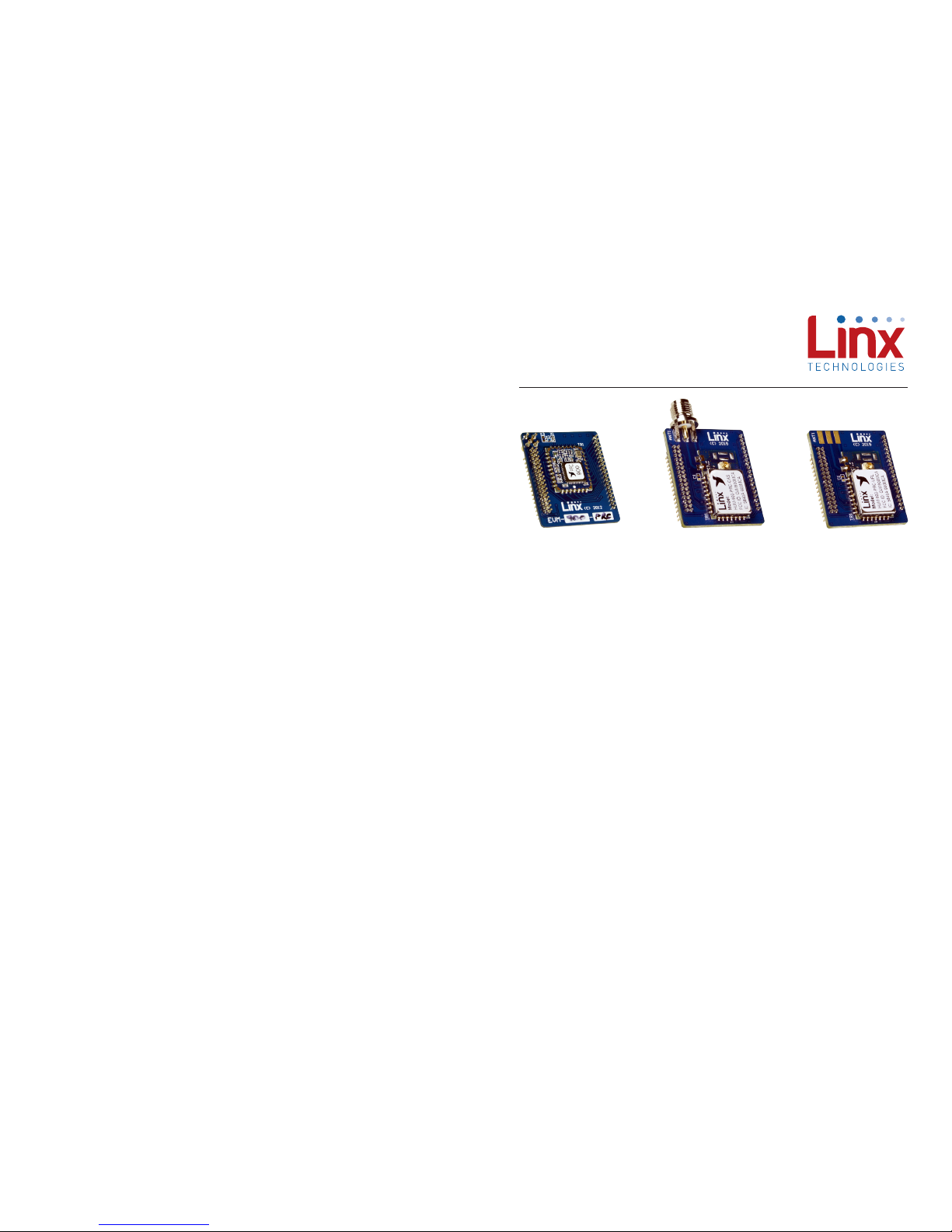
There are three versions of the evaluation module, populated with the
three versions of the HumPRCTM Series module. The standard version has
the standard module and an MMCX connector for use with the Master
Development System. The “-CAS” version has an edge-mount RP-SMA
connector for the antenna. The “-UFL” version uses the module’s on-board
U.FL connector for the antenna.
HumPRC
TM
Series Evaluation Module
Data Guide
Revised 9/18/2017
Figure 1: HumPRCTM Series Evaluation Modules; from left: EVM-***-PRC, EVM-***-PRC-CAS, EVM-***-PRC-UFL
Page 4
– –
– –
2 3
Ordering Information ElectricalSpecications
Figure 2: Ordering Information
Figure 4: Electrical Specifications
Please see the HumPRCTM Series Transceiver module data guide for full
electrical specifications.
Warning: This product incorporates numerous static-sensitive
components. Always wear an ESD wrist strap and observe proper ESD
handling procedures when working with this device. Failure to observe
this precaution may result in module damage or failure.
Absolute Maximum Ratings
Figure 3: Absolute Maximum Ratings
Absolute Maximum Ratings
Supply Voltage V
cc
−0.3 to +3.9 VDC
Any Input or Output Pin −0.3 to V
CC
+ 0.3 VDC
RF Input 0 dBm
Operating Temperature −40 to +85 ºC
Storage Temperature −40 to +85 ºC
Exceeding any of the limits of this section may lead to permanent damage to the device.
Furthermore, extended operation at these maximum ratings may reduce the life of this
device.
HumPRCTM Series Transceiver Specifications
Parameter Symbol Min. Typ. Max. Units Notes
Power Supply
Operating Voltage V
CC
2.0 3.6 VDC
TX Supply Current l
CCTX
at +10dBm 40.5 41.5 mA 1,2
at 0dBm 22 24 mA 1,2
RX Supply Current l
CCRX
23.5 24.5 mA 1,2,3
Power-Down Current l
PDN
0.7 1.4 µA 1,2
RF Section
Operating Frequency Band F
C
MHz
EVM-900-PRC 902 928 MHz
EVM-868-PRC 863 870 MHz
RF Data Rate
EVM-900-PRC 19.2 152.34 kbps
EVM-868-PRC 38.4 kbps
Serial Data Rate 9.6 115.2 kbps
Receiver Sensitivity 5
EVM-900-PRC @min rate –98 –101 dBm 5
EVM-900-PRC @max rate –91 –94 dBm 5
EVM-868-PRC –97 –100 dBm 5
Output Power P
O
EVM-900-PRC +8.5 +9.5 dBm 6
EVM-868-PRC +8.5 +10.6 dBm 6
Antenna Port
RF Impedance R
IN
50 Ω 4
Environmental
Operating Temp. Range −40 +85 ºC 4
1. Measured at 3.3V V
CC
2. Measured at 25ºC
3. Input power < -60dBm
4. Characterized but not tested
5. PER = 5%
6. Into a 50-ohm load
Ordering Information
Part Number Description
EVM-***-PRC
HumPRCTM Series Carrier Board, Not Certified, Through-Hole Pin
Interface, MMCX Connector for the Development System
EVM-***-PRC-CAS
HumPRCTM Series Carrier Board, Certified, Through-Hole Pin
Interface, RP-SMA Connector
EVM-***-PRC-UFL
HumPRCTM Series Carrier Board, Certified, Through-Hole Pin
Interface, U.FL Connector
HUM-***-PRC
HumPRCTM Series Remote Control Transceiver, Castellation
Interface, External Antenna Connection
HUM-***-PRC-CAS
HumPRCTM Series Remote Control Transceiver, Certified,
Castellation Interface, External Antenna Connection
HUM-***-PRC-UFL
HumPRCTM Series Remote Control Transceiver, Certified,
Castellation Interface, U.FL Connector
MDEV-***-PRC HumPRCTM Series Master Development System
MDEV-PGDOCK Development System Programming Dock
MDEV-PROTO Development System Prototype Board
CON-SOC-EVM EVM Module Socket Kit
*** = Frequency; 868, 900MHz
Page 5
– –
– –
4 5
7 MODE_IND
9 CMD_DATA_IN
11 LATCH_EN
13 ACK_EN
15 CMD_DATA_OUT
17 VCC
19 C0
21 C1
23 NC
25 NC
27 NC
29 NC
31 NC
33 NC
35 NC
37 NC
GND 6
RESET 8
POWER_DOWN 10
NC 12
PAIR 14
LNA_EN 16
NC 18
PA_EN 20
NC 22
NC 24
NC 26
NC 28
NC 30
NC 32
NC 34
NC 36
41 S3
42 S4
43 S5
44 S6
45 S7
46 ACK_OUT
47 NC
48 NC
49 NC
50 NC
51 NC
52 NC
53 NC
54 NC
55 NC
56 NC
40 S2
39 S1
38 S0
ANTENNA 1 2-5 GND (RF Connector)
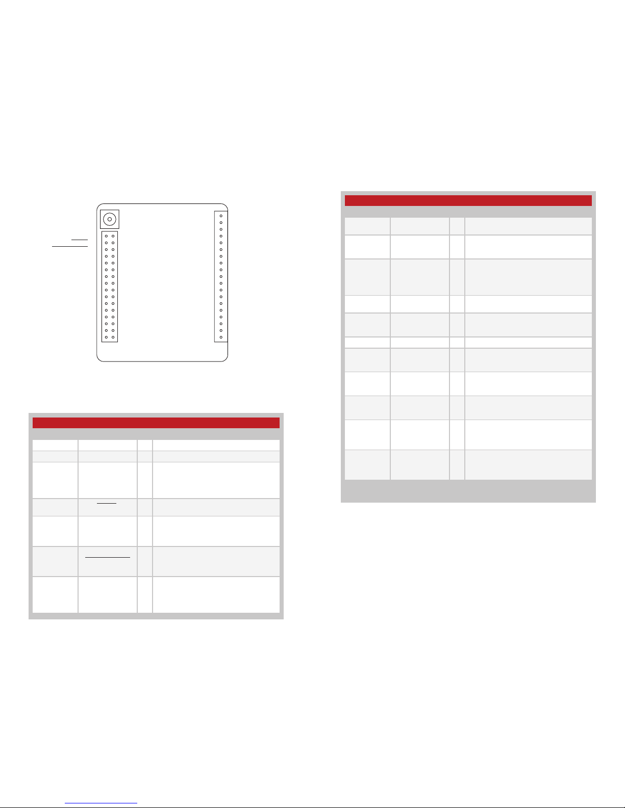
Figure 5: EVM-fff-PRC Pin Assignments
Pin Descriptions
Pin Assignments
Pin Descriptions
Pin Number Name I/O Description
1 ANTENNA — 50-ohm RF Antenna Port
2, 3, 4, 5, 6 GND — Ground
7 MODE_IND O
Mode Indicator. This line indicates module
activity. It can source enough current to drive
a small LED, causing it to flash. The duration
of the flashes indicates the module’s current
state.
8 RESET
2
I
This line resets the module when pulled low.
It should be pulled high for normal operation.
9 CMD_DATA_IN I
Command Data In. Input line for the serial
interface commands. If serial control is not
used, this line should be tied to supply to
minimize current consumption.
10 POWER_DOWN I
Power Down. Pulling this line low places the
module into a low-power state. The module
is not functional in this state. Pull high for
normal operation. Do not leave floating.
11 LATCH_EN I
If this line is high, then the status line outputs
are latched (a received command to activate
a status line toggles the output state). If low,
then the output lines are momentary (active
for as long as a valid signal is received).
Pin Descriptions
Pin Number Name I/O Description
12, 18,
22–37, 47-56
NC —
No Electrical Connection. Do not connect
any traces to these lines.
13 ACK_EN I
Pull this line high to enable the module to
send an acknowledgement message after a
valid control message has been received.
14 PAIR
1
I
A high on this line initiates the Pair process,
which causes two units to accept each
other’s transmissions. It is also used with
a special sequence to reset the module to
factory default configuration.
15 CMD_DATA_OUT O
Command Data Out. Output line for data
and serial commands
16 LNA_EN O
Low Noise Amplifier Enable. This line is
driven high when receiving. It is intended to
activate an optional external LNA.
17 VCC — Supply Voltage
19 C0 I
This line sets the input/output direction for
status lines S0-S3. When low, the lines are
outputs; when high they are inputs.
20 PA_EN O
Power Amplifier Enable. This line is driven
high when transmitting. It is intended to
activate an optional external power amplifier.
21 C1 I
This line sets the input/output direction for
status lines S4-S7. When low, the lines are
outputs; when high they are inputs.
38–45 S0–S7
1
I/O
Status Lines. Each line can be configured
as either an input to register button or
contact closures or as an output to control
application circuitry.
46 ACK_OUT O
This line goes high when the module
receives an acknowledgement message
from another module after sending a control
message.
1. These lines have an internal 20kΩ pull-down resistor
2. These lines have an internal 10kΩ pull-up resistor
Figure 6: EVM-fff-PRC Pin Descriptions
Page 6
– –
– –
6 7
Schematic
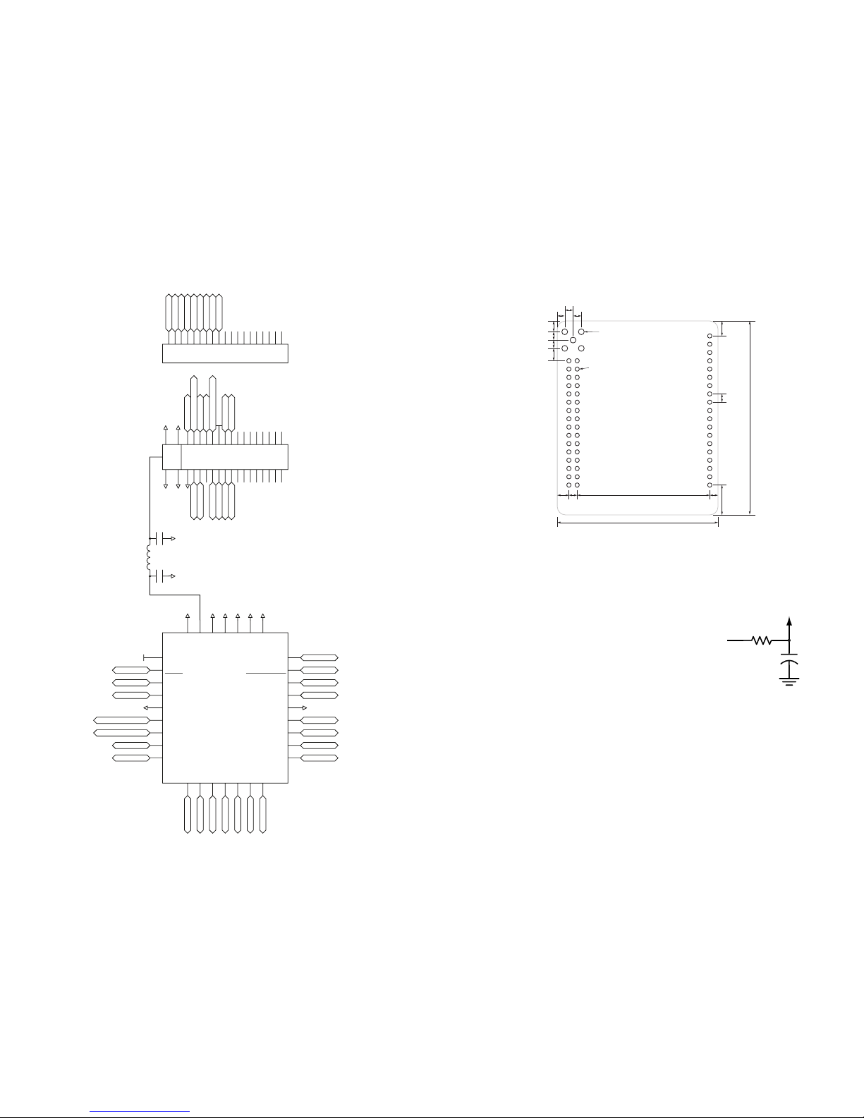
Figure 7 shows the schematic diagram for the evaluation module.
Pad Layout
Figure 8 shows the recommended PCB layout for the evaluation module.
Power Supply Requirements
The module does not have an internal
voltage regulator, therefore it requires a clean,
well-regulated power source. The power supply
noise should be less than 20mV. Power supply
noise can significantly affect the module’s
performance, so providing a clean power supply
for the module should be a high priority during
design.
A 10Ω resistor in series with the supply followed by a 10μF tantalum
capacitor from Vcc to ground helps in cases where the quality of supply
power is poor. This filter should be placed close to the module’s supply
lines. These values may need to be adjusted depending on the noise
present on the supply line.
5 x Ø0.035”
51 x Ø0.026”
0.05”
0.05”
0.05”
0.05”
0.05”
0.09”
0.18”
0.80”
0.05”
0.07”
0.045”
0.075”
0.065”
1.17”
0.97”
0.05”
S7
38394041424344454647484950515253545556
ACK_OUT
S0S1S2S3S4S5S6
S7PAIR
MODE_IND
LATCH_EN
ACK_EN
RESET
PDN
NC1
CMD_DATA_IN
CMD_DATA_OUT
LNA_EN
PAIR
PA_EN
RESETPDN
NC1
LNA_EN
MODE_IND
LATCH_EN
ACK_EN
ACK_OUT
S0
S1
S2
S3
S4
S5
S6
S7 C0
C1
C0
C1
1
23
45
67
89
10 11
12 13
14 15
16 17
18 19
20 21
22 23
24 25
26 27
28 29
30 31
32 33
34 35
36 37
J1
Carrier Interconnect
CMD_DATA_OUT
CMD_DATA_IN
X1
1.2pF
X2 5.3nH
GND
GND
GND
GND
GND
GND
GND
GND
GND
GND
GND
GND
GND
GND
VCC
VCC
PA_EN
GND
17
VCC
21
GND
18
RESET
22
LNA_EN
23
PA_EN
24
CMD_DATA_OUT
26
CMD_DATA_IN
27
ACK_EN
28
PAIR
29
S6
2
GND
25
1
MODE_IND30ACK_OUT31GND32S53S4
4
ANT
19
GND
20
S3
5
S2
6
S1
7
S0
8
C0
10
C1
11
POWER_DOWN
12
LATCH_EN
13
GND
9
GND16GND15GND
14
TR1
X3
DNP
GND
HUM-***-PRC
Figure 8: EVM-fff-PRC PCB Layout Dimensions
Figure 7: EVM-fff-PRC Schematic
+
10Ω
10µF
Vcc IN
Vcc TO
MODULE
Figure 9: Supply Filter
Page 7
– –
– –
8 9
29.72 mm
(1.170 in)
26.64 mm
(0.970 in)
2.79 mm
(0.110 in)
6.09 mm
(0.240 in)
8.35 mm
(0.329 in)
29.72 mm
(1.170 in)
26.64 mm
(0.970 in)
5.98 mm
(0.235 in)
37.43 mm
(1.473 in)
6.53 mm
(0.257 in)
9.83 mm
(0.387 in)
Ø6.35 mm
(0.25 in)
Ø7.93 mm
(0.312 in)
4.24 mm
(0.167 in)
11.51 mm
(0.453 in)
7.54 mm
(0.297 in)
29.72 mm
(1.170 in)
26.64 mm
(0.970 in)
6.53 mm
(0.257 in)
9.83 mm
(0.387 in)
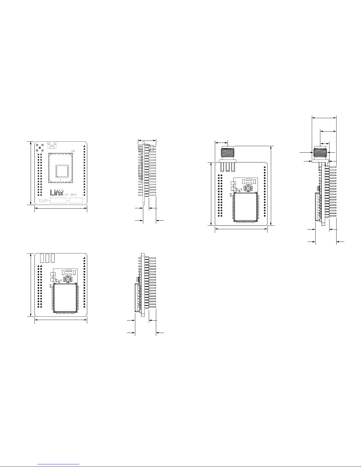
Dimensions
The figures below show the dimensions for the three variants of the
module.
Figure 10: EVM-fff-PRC Dimensions
Figure 11: EVM-fff-PRC-UFL Dimensions
Figure 12: EVM-fff-PRC-CAS Dimensions
Page 8

– –
– –
10 11
Notes
Page 9

Disclaimer
Linx Technologies is continually striving to improve the quality and function of its products. For this reason, we
reserve the right to make changes to our products without notice. The information contained in this Data Guide
is believed to be accurate as of the time of publication. Specifications are based on representative lot samples.
Values may vary from lot-to-lot and are not guaranteed. “Typical” parameters can and do vary over lots and
application. Linx Technologies makes no guarantee, warranty, or representation regarding the suitability of any
product for use in any specific application. It is the customer’s responsibility to verify the suitability of the part for
the intended application. NO LINX PRODUCT IS INTENDED FOR USE IN ANY APPLICATION WHERE THE SAFETY
OF LIFE OR PROPERTY IS AT RISK.
Linx Technologies DISCLAIMS ALL WARRANTIES OF MERCHANTABILITY AND FITNESS FOR A PARTICULAR
PURPOSE. IN NO EVENT SHALL LINX TECHNOLOGIES BE LIABLE FOR ANY OF CUSTOMER’S INCIDENTAL OR
CONSEQUENTIAL DAMAGES ARISING IN ANY WAY FROM ANY DEFECTIVE OR NON-CONFORMING PRODUCTS
OR FOR ANY OTHER BREACH OF CONTRACT BY LINX TECHNOLOGIES. The limitations on Linx Technologies’
liability are applicable to any and all claims or theories of recovery asserted by Customer, including, without
limitation, breach of contract, breach of warranty, strict liability, or negligence. Customer assumes all liability
(including, without limitation, liability for injury to person or property, economic loss, or business interruption) for
all claims, including claims from third parties, arising from the use of the Products. The Customer will indemnify,
defend, protect, and hold harmless Linx Technologies and its officers, employees, subsidiaries, affiliates,
distributors, and representatives from and against all claims, damages, actions, suits, proceedings, demands,
assessments, adjustments, costs, and expenses incurred by Linx Technologies as a result of or arising from any
Products sold by Linx Technologies to Customer. Under no conditions will Linx Technologies be responsible for
losses arising from the use or failure of the device in any application, other than the repair, replacement, or refund
limited to the original product purchase price. Devices described in this publication may contain proprietary,
patented, or copyrighted techniques, components, or materials. Under no circumstances shall any user be
conveyed any license or right to the use or ownership of such items.
©2017 Linx Technologies. All rights reserved.
The stylized Linx logo, Wireless Made Simple, WiSE, CipherLinx and the stylized CL logo are trademarks of Linx Technologies.
Linx Technologies
159 Ort Lane
Merlin, OR, US 97532
Phone: +1 541 471 6256
Fax: +1 541 471 6251
www.linxtechnologies.com
 Loading...