

Linx EVM-915-DTS-FCR, EVM-915-DTS-FCS, EVM-915-DTS, EVM-915-DTS-BRZ, EVM-915-DTS-BZS Data Manual
Page 1

EVM-915-DTS
Data Guide
(Preliminary)
Page 2

Table of Contents
1
Description
2
Ordering Information
2
Electrical Specications
4
Pin Assignments
5
Pin Descriptions
6
PCB Footprint
7
Schematic Diagram
8
Usage Guidelines for FCC Compliance
8
Antenna Selection
9
Module Modication
9
End Product Labeling Requirements
9
Additional FCC Testing Requirements
10
FCC Statements of Modular Compliance
11
Customer FCC Warning Requirements
Page 3

EVM-915-DTS
Data Guide (Preliminary)
Description
The EVM-915-DTS features our powerful
and popular TRM-915-DTS module in a FCC
modular approved solution. It is designed
to greatly simplify implementation of the
TRM-915-DTS module into a working design
without the complications of FCC testing.
The module combines a state-of-the art low
power wireless transceiver with a powerful multipoint-to-multipoint protocol
controller to form a transparent wireless communication solution capable
of replacing wires in almost any RS-232/422/485 application. With a 111
dB link budget and very low power operation modes, the TRM-915-DTS
module is excellent for AMR, RFID, Home Automation, and any other
application requiring long range (<1500ft. , line of sight) and long
battery life.
Figure 1: EVM-915-DTS Module
The module is designed to be totally transparent. No special addressing
or formatting of data is required. Data is validated using an internally
generated CRC-16 and encoded using a proprietary algorithm.
Multiple modules can operate on the same channel because of the built-in
carrier-sense-multiple-access (CSMA) protocol.
– –
1
Revised 6/12/12Preliminary Draft
Page 4
Ordering Information
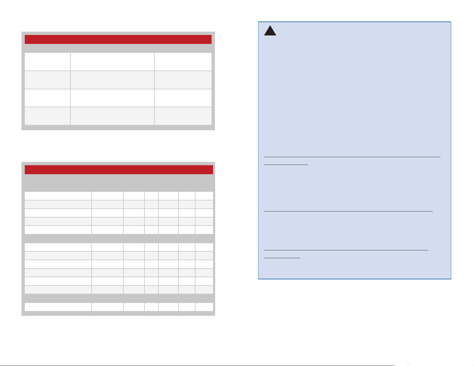
Ordering Information
Product Part No. Description Radiotronix Part No.
EVM-915-DTS-FCS
EVM-915-DTS-FCR
EVM-915-DTS-BRZ
EVM-915-DTS-BZS
Figure 2: Ordering Information
TRM-915-DTS Evaluation Module,
915MHz, Straight RP-SMA Connector,
FCC Approved
TRM-915-DTS Evaluation Module,
915MHz, Right Angle RP-SMA
Connector, FCC Approved
TRM-915-DTS Evaluation Module,
915MHz, Right Angle RP-SMA
Connector, Brazil Anatel Approved
TRM-915-DTS-BRZ Evaluation
Module, 915MHz, Straight RP-SMA
Connector, Brazil Anatel Approved
Wi.232DTS-FCC-ST-R
Wi.232DTS-FCC-RA-R
Wi.232DTSB-EVM-RA-R
Wi.232DTSB-EVM-ST-R
Warning: Linx radio frequency (“RF”) products may be used to
!
control machinery or devices remotely, including machinery or devices
that can cause death, bodily injuries, and/or property damage if
improperly or inadvertently triggered, particularly in industrial settings
or other applications implicating life-safety concerns. No Linx
Technologies product is intended for use in any application without
redundancies where the safety of life or property is at risk.
The customers and users of devices and machinery controlled with
RF products must understand and must use all appropriate safety
procedures in connection with the devices, including without limitation,
using appropriate safety procedures to prevent inadvertent triggering
by the user of the device and using appropriate security codes to
prevent triggering of the remote controlled machine or device by users
of other remote controllers.
Electrical Specications
Electrical Specifications
Parameter Designation Min. Typ. Max. Units Notes
Power Supply
Operating Voltage V
Supply Current I
Receive 25 mA
Transmit, Po = 0dBm 35 mA
Transmit, Po = 13dBm 60 mA
Digital Interface
Output
Logic Low V
Logic High V
Input
Logic Low V
Logic High V
Environmental
Operating Temperature Range –40 85 °C
Figure 3: Electrical Specifications
CC
CC
OL
OH
IL
IH
4 12 VDC
0 0.4 VDC
2.5 V
0 0.3*VCCVDC
0.7*V
CC
CC
V
CC
VDC
VDC
All RF products are susceptible to RF interface that can prevent
communication. RF products without frequency agility or hopping
implemented are more subject to interference. This module does
not have frequency agility built in, but the developer can implement
frequency agility with a microcontroller and the example code in Linx
Reference Guide RG-00101.
Do not use any Linx product over the limits in this data guide.
Excessive voltage or extended operation at the maximum voltage
could cause product failure. Exceeding the reflow temperature profile
could cause product failure which is not immediately evident.
Do not make any physical or electrical modifications to any
Linx product. This will void the warranty and regulatory and UL
certifications and may cause product failure which is not immediately
evident.
– – – –
32
Preliminary DraftPreliminary Draft
Page 5
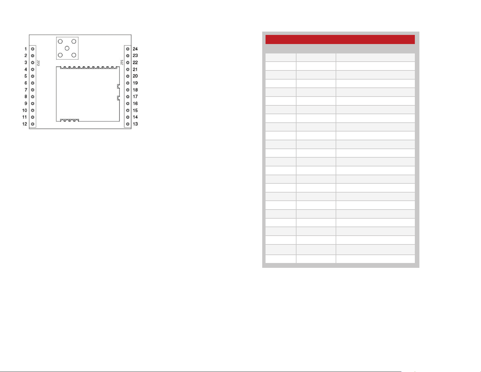
Pin Assignments
Figure 4: Pin Assignments
Pin Descriptions
Pin Descriptions
Pin No. Name Description
1 Vcc 4V to 12V Supply Voltage
2 RXD0 Serial Port Receive Data
3 TXD0 Serial Port Transmit Data
4 CTS0 Serial Port Clear To Send
5 COMMAND Command
6 N/C No Electrical Connection
7 N/C No Electrical Connection
8 N/C No Electrical Connection
9 N/C No Electrical Connection
10 N/C No Electrical Connection
11 GND Analog Ground
12 GND Analog Ground
13 GND Analog Ground
14 GND Analog Ground
15 N/C No Electrical Connection
16 N/C No Electrical Connection
17 N/C No Electrical Connection
18 N/C No Electrical Connection
19 N/C No Electrical Connection
20 N/C No Electrical Connection
21 N/C No Electrical Connection
22 N/C No Electrical Connection
23 GND Analog Ground
24 GND Analog Ground
Figure 5: Pin Descriptions
– – – –
54
Preliminary DraftPreliminary Draft
Page 6
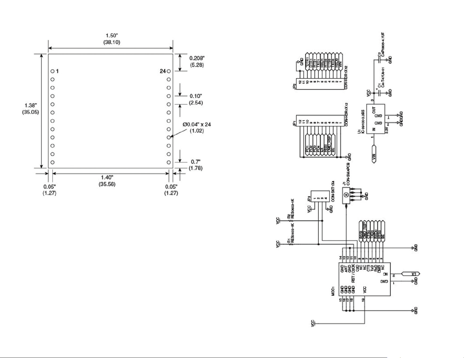
PCB Footprint
Schematic Diagram
Figure 6: PCB Footprint
Figure 7: Schematic
– – – –
76
Preliminary DraftPreliminary Draft
Page 7

Usage Guidelines for FCC Compliance
The EVM-915-DTS modules have been awarded a FCC and Anatel
modular approvals. That means that this module, when integrated into
your end product, requires no FCC part 15 or Anatel testing as long as the
following guidelines are met. Failure to meet any of the following guidelines
will prevent the inheritance of the FCC and IC modular certifications.
Antenna Selection
In order to maintain compliance with FCC and Anatel regulations, an
antenna with no more than 3dBi gain must be used. This module has been
tested with the following antennas:
Antenna Selection
Linx Part No. Antenna Type Antenna Gain
ANT-916-CW-QW RP ¼ Wave Helical 2dBi
ANT-916-CW-HW RP ½ Wave Dipole 2.5dBi
Figure 8: Antenna Selection
When operating in DTS mode the module may be used with any of the
above antennas and maintain the requirements of the FCC grant. When
operating the module in LP mode, it must be used with the approved ¼
wave antenna. The module may not be used with the ½ wave dipole
antenna in LP mode.
An approved antenna must be directly attached to the module’s reversepolarity SMA connector in the final application to inherit the FCC and Anatel
modular certification.
Module Modication
The module must not be physically altered in any way. If any connections
are made to the modules that bypass the module pins, socket or antenna
connector, neither the FCC nor Anatel modular certification can be
inherited.
End Product Labeling Requirements
Pursuant to FCC public notice DA 00-1407, the end product must be
labeled on its exterior with the following:
Additional FCC Testing Requirements
While the module’s FCC certification can be inherited if the guidelines
are met, additional testing will be required to achieve full FCC compliance
for the end-product. The integrator is required to perform unintentional
radiator testing on the final product per FCC sections 15.107 and 15.109.
Additional product-specific testing might be required. Please contact the
FCC regarding regulatory requirements for your application. Ultimately is it
the integrator’s responsibility to show that their product complies with the
regulations applicable to their product.
Customer FCC Warning Requirements
The end-product’s user’s manual must contain the following or equivalent
statements.
FCC NOTICE (Containing FCC ID: Q7V-3F090003X)
The RF module (FCC ID: Q7V-3F090009X) contained within this device complies with the
rules set forth in Part 15 by the Federal Communications Commission. Operation is subject
to the following conditions:
1. This device may not cause harmful interference
2. This device must accept any interference received, including interference that may
cause undesired operation.
3. An approved antenna must be directly coupled to the module’s RP-SMA
connector.
4. The module must not be modied in any way. Coupling of external circuitry must not
bypass the provided connectors.
5. The antenna used for this transceiver must not be co-located or operating in
conjunction with any other antenna or transmitter.
Any changes or modications could void the user’s authority to operate the
equipment.
FCC Pre-certied EVM-915-DTS
FCC ID: Q7V-3F090009X
“Contains FCC ID: Q7V-3F090003X”
– – – –
98
Preliminary DraftPreliminary Draft
Page 8

FCC Statements of Modular Compliance
FCC NOTICE (FCC ID: Q7V-3F090009X)
Brazil Anatel Labeling Requirements
The Brazil version, the EVM-915-250-BZx, has been tested and complies
with the Anatel regulations for sale in Brazil.
This device complies with the rules set forth in Part 15 by the Federal
Communications Commission. Operation is subject to the following two conditions:
1. This device may not cause harmful interference
2. This device must accept any interference received, including interference that may
cause undesired operation.
Any changes or modications not expressly approved by Linx Technologies could void
the user’s authority to operate the equipment.
The EVM-915-DTS module is provided with an inheritable FCC Modular
Certication. This certication may be inherited in an end-user product, negating the
need for FCC part 15 intentional radiator testing on this module, provided that the
following guidelines are met:
1. An approved antenna must be directly coupled to the module’s RP-SMA connector.
2. The module must not be modied in any way. Coupling of external circuitry must not
bypass the provided connectors.
3. End product must be externally labeled with “Contains FCC ID: Q7V-3F090009X”
4. The end product’s user’s manual must contain an FCC statement equivalent to that
listed on page 11 of this manual.
5. The antenna used for this transceiver must not be co-located or operating in
conjunction with any other antenna or transmitter.
6. The integrator must not provide any information to the end-user on how to install or
remove the module from the end-product.
Este equipamento opera em caráter secundário, isto é, não tem
direito à proteção contra interferência prejudicial, mesmo de estações do
mesmo tipo, e não pode causar interferência a sistemas operando em
caráter primário.
Anatel label
The integrator is required to perform unintentional radiator testing on the nal product
per FCC sections 15.107 and 15.109.
FCC Pre-certied EVM-915-DTS
FCC ID: Q7V-3F090009X
– – – –
1110
Preliminary DraftPreliminary Draft
Page 9

Linx Technologies
159 Ort Lane
Merlin, OR, US 97532
3090 Sterling Circle, Suite 200
Boulder, CO 80301
Phone: +1 541 471 6256
Fax: +1 541 471 6251
www.linxtechnologies.com
Disclaimer
Linx Technologies is continually striving to improve the quality and function of its products. For this reason, we
reserve the right to make changes to our products without notice. The information contained in this Data Guide
is believed to be accurate as of the time of publication. Specifications are based on representative lot samples.
Values may vary from lot-to-lot and are not guaranteed. “Typical” parameters can and do vary over lots and
application. Linx Technologies makes no guarantee, warranty, or representation regarding the suitability of any
product for use in any specific application. It is Customer’s responsibility to verify the suitability of the part for the
intended application. At Customer’s request, Linx Technologies may provide advice and assistance in designing
systems and remote control devices that employ Linx Technologies RF products, but responsibility for the ultimate
design and use of any such systems and devices remains entirely with Customer and/or user of the RF products.
LINX TECHNOLOGIES DISCLAIMS ANY AND ALL WARRANTIES OF MERCHANTABILITY AND FITNESS FOR A
PARTICULAR PURPOSE. IN NO EVENT SHALL LINX TECHNOLOGIES BE LIABLE FOR ANY CUSTOMER’S OR
USER’S INCIDENTAL OR CONSEQUENTIAL DAMAGES ARISING OUT OF OR RELATED TO THE DESIGN OR USE
OF A REMOTE CONTROL SYSTEM OR DEVICE EMPLOYING LINX TECHNOLOGIES RF PRODUCTS OR FOR ANY
OTHER BREACH OF CONTRACT BY LINX TECHNOLOGIES. CUSTOMER AND/OR USER ASSUME ALL RISKS
OF DEATH, BODILY INJURIES, OR PROPERTY DAMAGE ARISING OUT OF OR RELATED TO THE USE OF LINX
TECHNOLOGIES RF PRODUCTS, INCLUDING WITH RESPECT TO ANY SERVICES PROVIDED BY LINX RELATED
TO THE USE OF LINX TECHNOLOGIES RF PRODUCTS. LINX TECHNOLOGIES SHALL NOT BE LIABLE UNDER ANY
CIRCUMSTANCES FOR A CUSTOMER’S, USER’S, OR OTHER PERSON’S DEATH, BODILY INJURY, OR PROPERTY
DAMAGE ARISING OUT OF OR RELATED TO THE DESIGN OR USE OF A REMOTE CONTROL SYSTEM OR DEVICE
EMPLOYING LINX TECHNOLOGIES RF PRODUCTS.
The limitations on Linx Technologies’ liability are applicable to any and all claims or theories of recovery asserted
by Customer, including, without limitation, breach of contract, breach of warranty, strict liability, or negligence.
Customer assumes all liability (including, without limitation, liability for injury to person or property, economic loss,
or business interruption) for all claims, including claims from third parties, arising from the use of the Products.
Under no conditions will Linx Technologies be responsible for losses arising from the use or failure of the device
in any application, other than the repair, replacement, or refund limited to the original product purchase price.
Devices described in this publication may contain proprietary, patented, or copyrighted techniques, components,
or materials.
All rights reserved. ©2012 Linx Technologies
The stylized Linx logo, Wireless Made Simple, CipherLinx and the stylized CL logo are trademarks of Linx Technologies.
 Loading...