

Page 1
http://lintronic.dk
Get started
TT455-RT-238
Quick guide
Updated 190227
LinTronic
Page 2

http://lintronic.dk
Get started
In this guide:
Step 1 - Getting started
Step 2 - CommandList
Step 3 - Memory Map
Step 4 - MyScore
Step 5 - MyFeedback
Step 6 - Dealers projects
Page 3
http://lintronic.dk
Get started
Step 1 - Getting started
This is just a Quick Guide to get you started.
When you have studied this Quick Guide
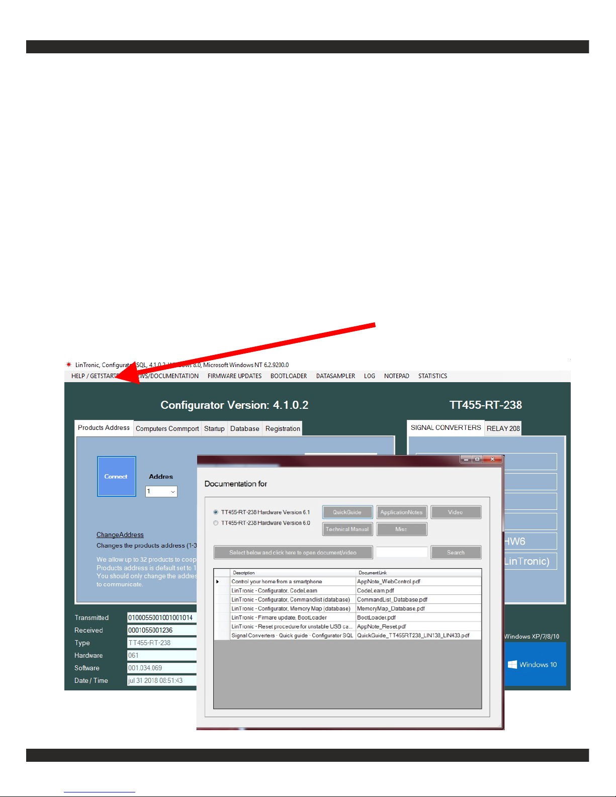
- we recommend you read it all then use the Configurators
HELP button to find the
manual for the CommandList
and Memory Map
Page 4
http://lintronic.dk
Get started
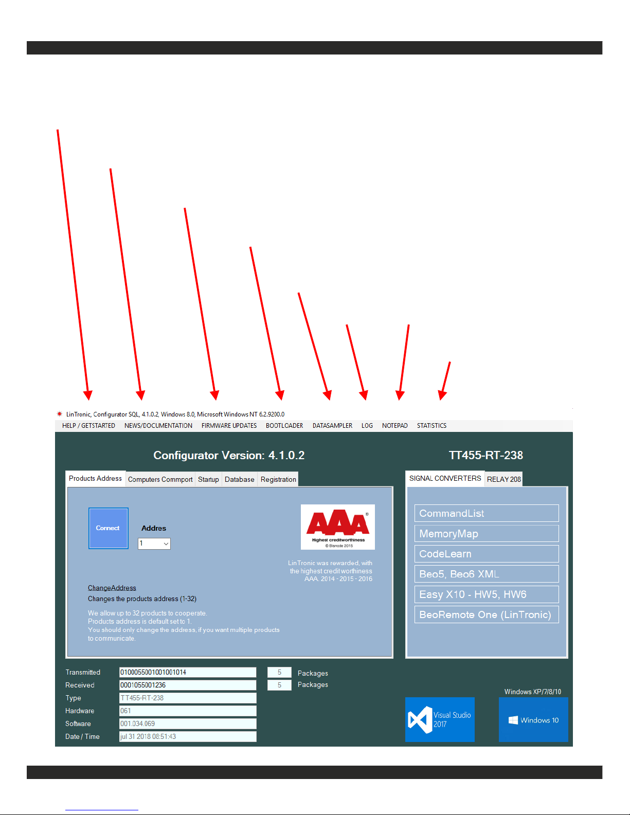
HELP / GET STARTED
- QuickGudes
NEWS / DOCUMENTATION
- manuals, videos
FIRMWARE UPDATES
- checks for updates of your products
BOOTLOADER
- updates your product
DATASAMPLER
- Comport monitor/control
LOG NOTEPAD
STATISTICS
- to be relased
Page 5

http://lintronic.dk
Get started
IMPORTANT
FIRST
1. Read next pages about triggers and actions, so you understand the relation.
2. Download and install Configurator.
3. Insert your license related email and password from your customer profile.
4. Connect ComCab cables.
5. Open comport in Configurator.
Then
6. Apply power to your product.
7. Make sure you understand the difference between the
Step 1, CommandList and
Step 2, Memory Map
FAQ:
Our products are designed to work as standalone products with the possibility
of controlling other products by for example infrared, RS232 or relays.
Therefore a USB connector is not very useful in our products, as USB require
that the product is connected to a computer only and we would not be able to
control TV’s, projectors, light systems, relays, etc. etc.
It is strongly recommended that you familiarize yourself with the technical
manual of the product and the dedicated manuals for CommandList and
Memory Map.
See http://lintronic.dk | Support | Get started.
Best regards,
Michael Lindgaard
Page 6
http://lintronic.dk
Get started
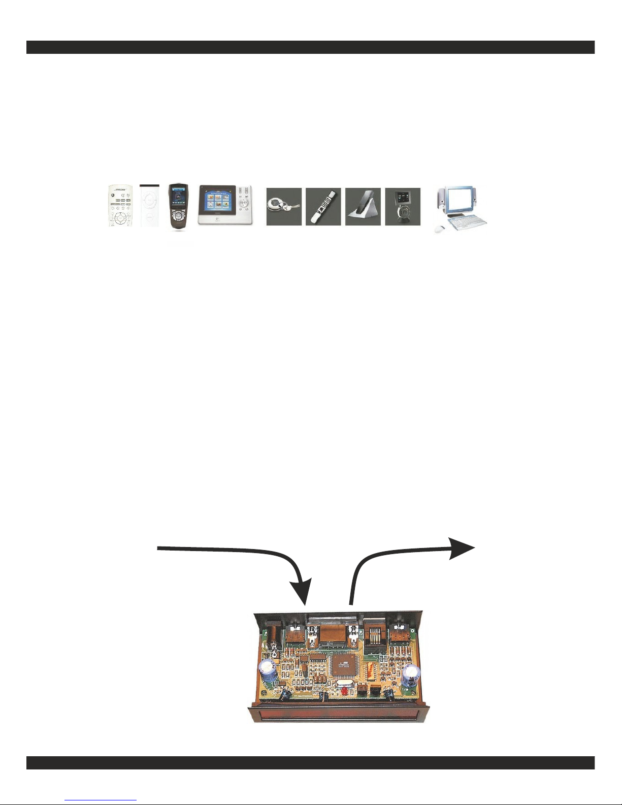
Triggers
Actions
Triggers and Actions
Our products are controlled by Triggers, which causes Actions to be executed.
- A remote control command (Bang&Olufsen, Apple, Bose, LinTronic, Logitech, NEC, Samsung, etc.)
- A computer command (RS232 comport working on 2400 - 38400 bps)
- A switch, contact, relay, motion detector, etc. - connected to one or both of the 2 digital inputs
- An activation of the buttons, on the external receiver 8087030
- A 433 MHz signal from a remote control, motion/door/windows sensor, etc.
A Trigger can be for example:
Actions can be for example:
- InfraRed and/or RS232 signals for audio/video products, projectors, screens, curtains,
blinders, shades, light systems, relays, fireplaces, elevation beds, computer, etc.
- Digital or relay outputs for various purposes like relays, data-interface etc.
- 433 MHz signal controlling relays, doorbells, etc.
Page 7

http://lintronic.dk
Get started
Triggers and Actions
The way you instruct your product on how to be Triggered and what Actions to control, is by setting up
a project which combines the Triggers and Actions.
STEP 1 - COMMANDLIST / ACTIONS
Before you start configuring your product to carry out what you want it to do, you need to get hold of the
commands (Actions) to be carried out. These commands (Actions) are collected in the CommandList.
In the CommandList you can use commands from the built-in database, which are commands shared by
other users uploading their commands to the online database.
If your product is not already covered/supported/shared, then you can copy commands from your own
remote control. If commands cannot be decoded, we can build a new decoder.
We kindly ask you to upload these commands to our database later, when you have tested they work.
RS232
If your product can be controlled by RS232 commands, (more and more screens, projectors, light systems,
etc.) then it is recommended to use RS232 instead of InfraRed, as InfraRed (IR) is much easier disturbed
than RS232.
RS232 requires a cable from the RS232-connector of the product.
In case you want to control another product by RS232 commands, and we do not have the required
commands, then we must embed the commands into the firmware for the product and we provide you with
a set of virtual commands which will generate the commands.
RELAYS
We support both wired and wireless relays, as well as relays controlled by RS232.
CUSTOMIZED SOLUTIONS
We often participate in development of special firmware which will allow our product to carry out your
specific tasks. We work fast and our prices are very attractive.
STEP 2 - MEMORY MAP
The Memory Map is where you select your Triggers and associate them with the Actions to be carried
out.
Page 8
http://lintronic.dk
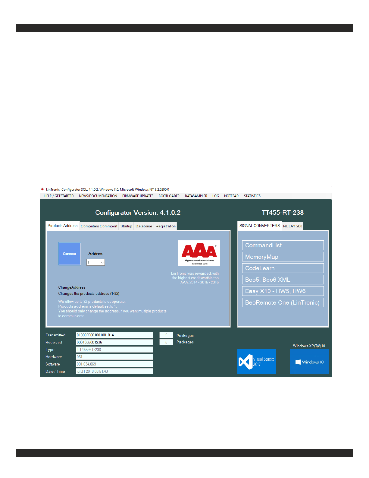
Visit - http://lintronic.dk | Support | Download
or
http://lintronic.dk/download.aspx
Download / install the Configurator
DOWNLOAD/INSTALL
Page 9
http://lintronic.dk
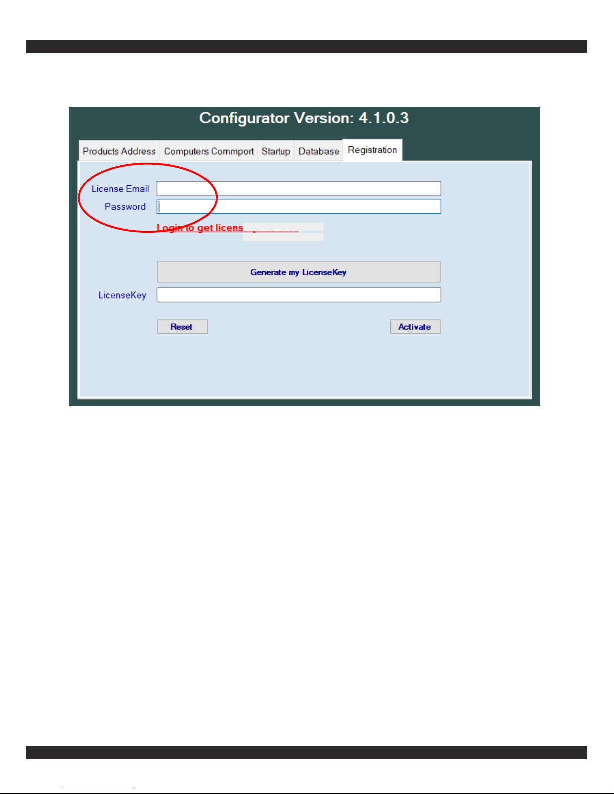
From your online Customer profile:
Enter the license related Email and Password
from your customer profile.
Then generate your LicenseKey.
Please note:
If you later change your email address, then
the login and the license email can be different
as we will keep the first email for your license.
DOWNLOAD/INSTALL
Page 10
http://lintronic.dk
Get started
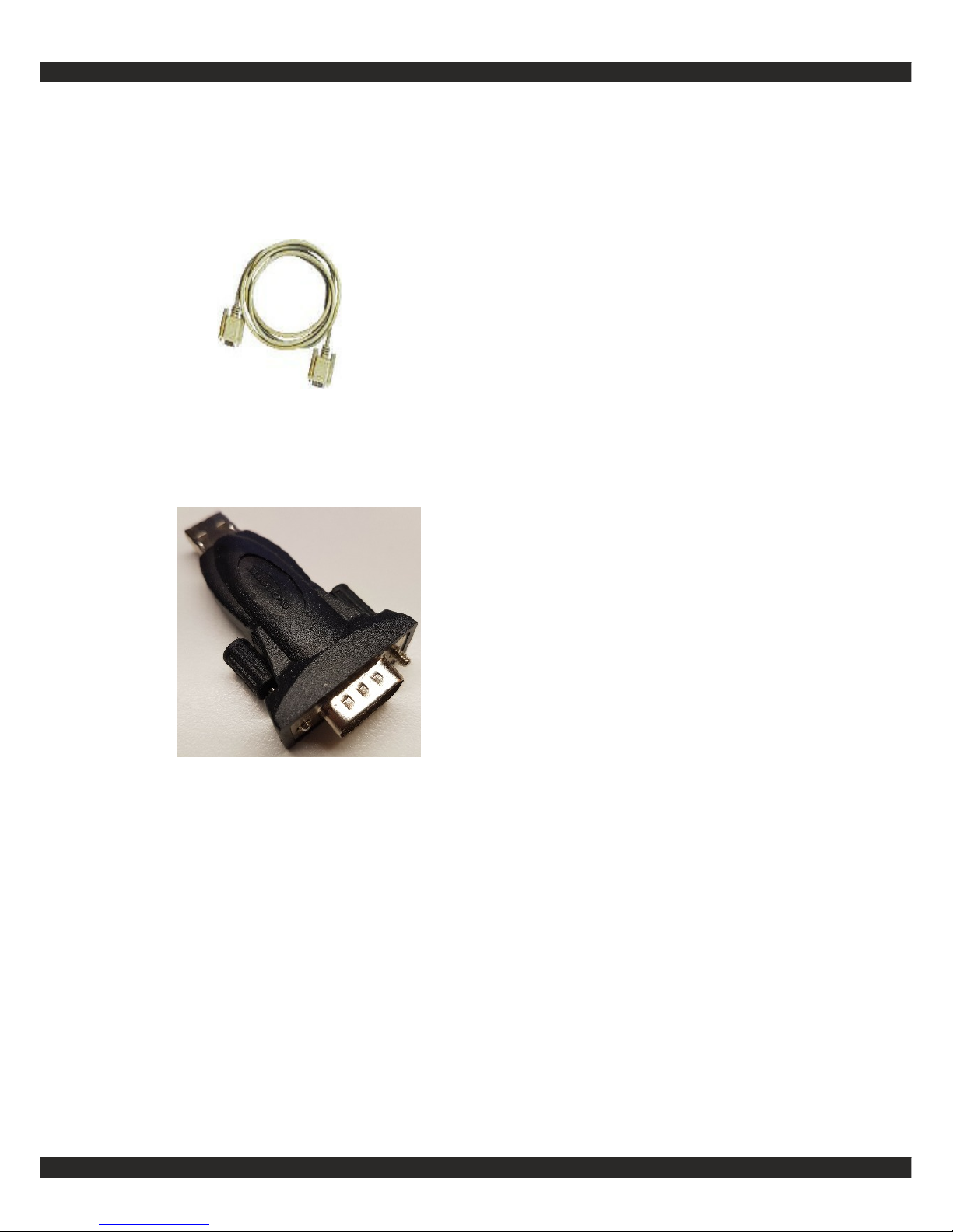
Connect communication cable
to the TT455-RT-238.
Insert cable into computers serial
commport.
Serial cable: ComCab-001
Connect communication cable
to the product.
Insert cable into computer.
Do NOT install the enclosed CD.
Let the Windows 10 computer
find the driver online and autoinstall.
Serial cable: ComCab-003
CONNECT
Page 11
http://lintronic.dk
Get started
Output
Power
Communication
Input Output
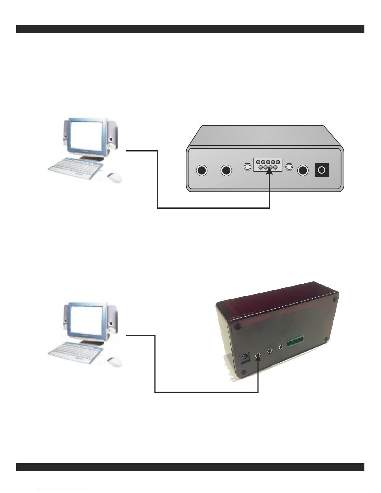
Connect computer cables
Insert ComCab-001 into TT455-RT-238 and insert ComCab-001
into computer, or
Insert ComCab-003 into TT455-RT-238 and insert ComCab-003
into computer.
CONNECT
Insert ComCab-004 into LIN-138/LIN-433
Insert ComCab-004 into ComCab-003
Insert ComCab-003 into computer
Page 12
http://lintronic.dk
Get started
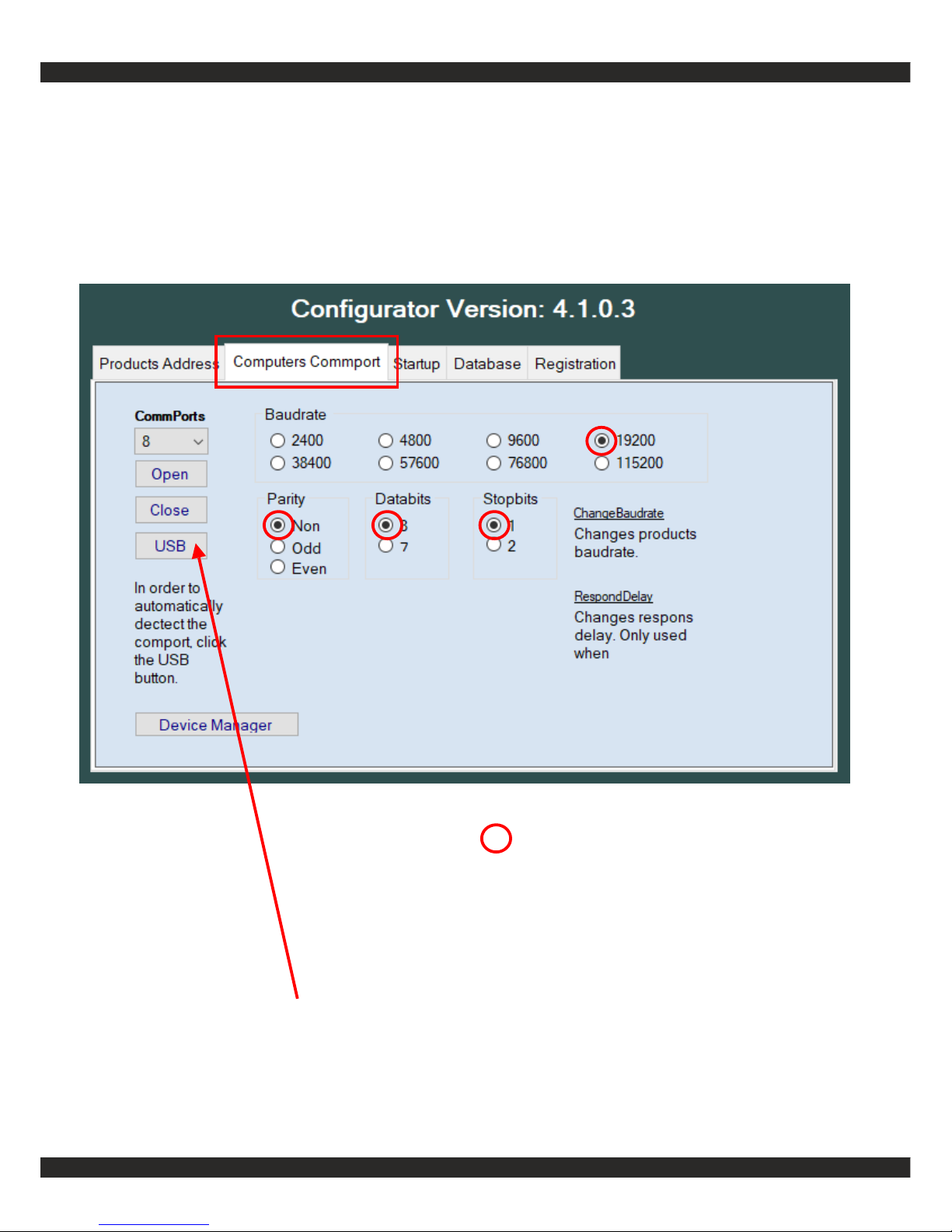
OPEN THE COMPORT ASSIGNED TO YOUR (USB) CABLE
CONNECT
= default
Click USB button in order to find USB port
Page 13
http://lintronic.dk
Get started
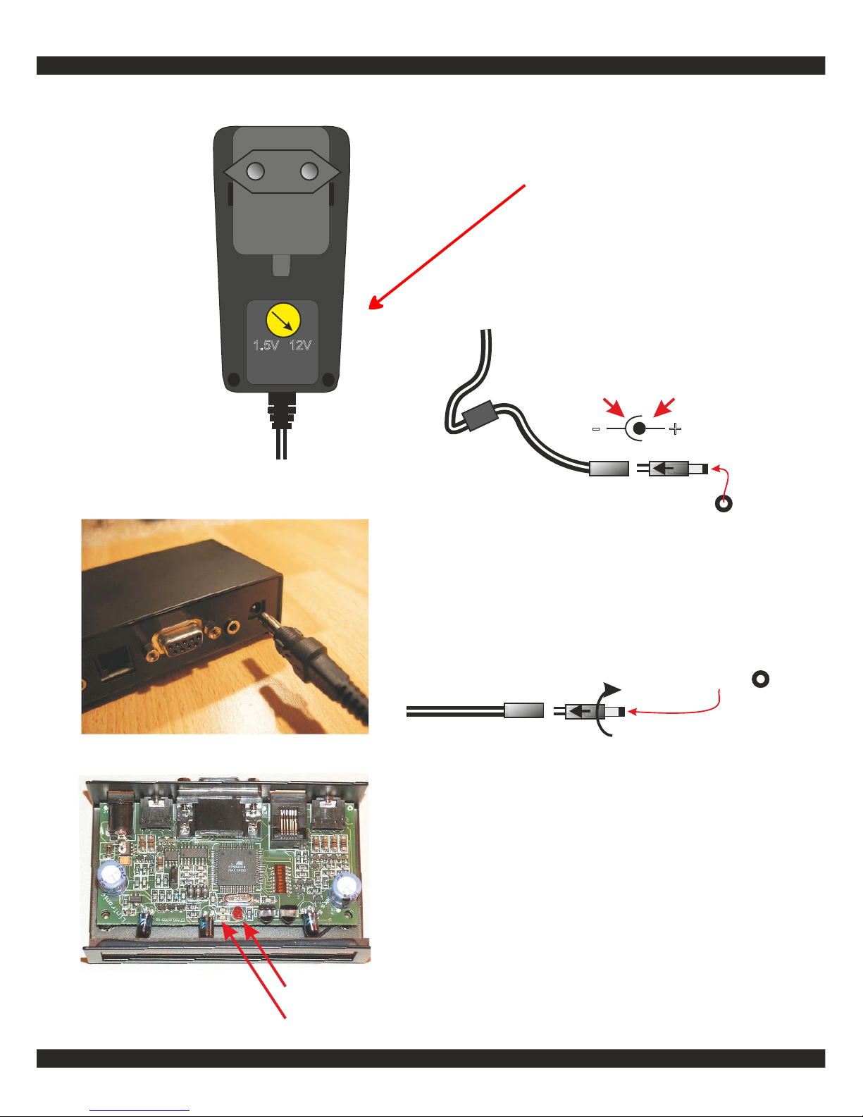
+
-
Negative ring Positive tip
2.1 mm
1)
Front LED should blink for 2 seconds
and then turn on for ½ a second.
2)
Heart beat indicator blinks every second.
This indicator is best viewed from the side.
Follow the red arrow below.
Connect power.
If front LED's do not blink, check power
is set for 12 volt or turn the power plug
in the cable. The -238 is protected
against wrong polarity.
2.1 mm
1)
2)
1.5V 12V
100-240 vac
5 0 / 6 0 H z
12 volt
CONNECT
Page 14
http://lintronic.dk
Get started
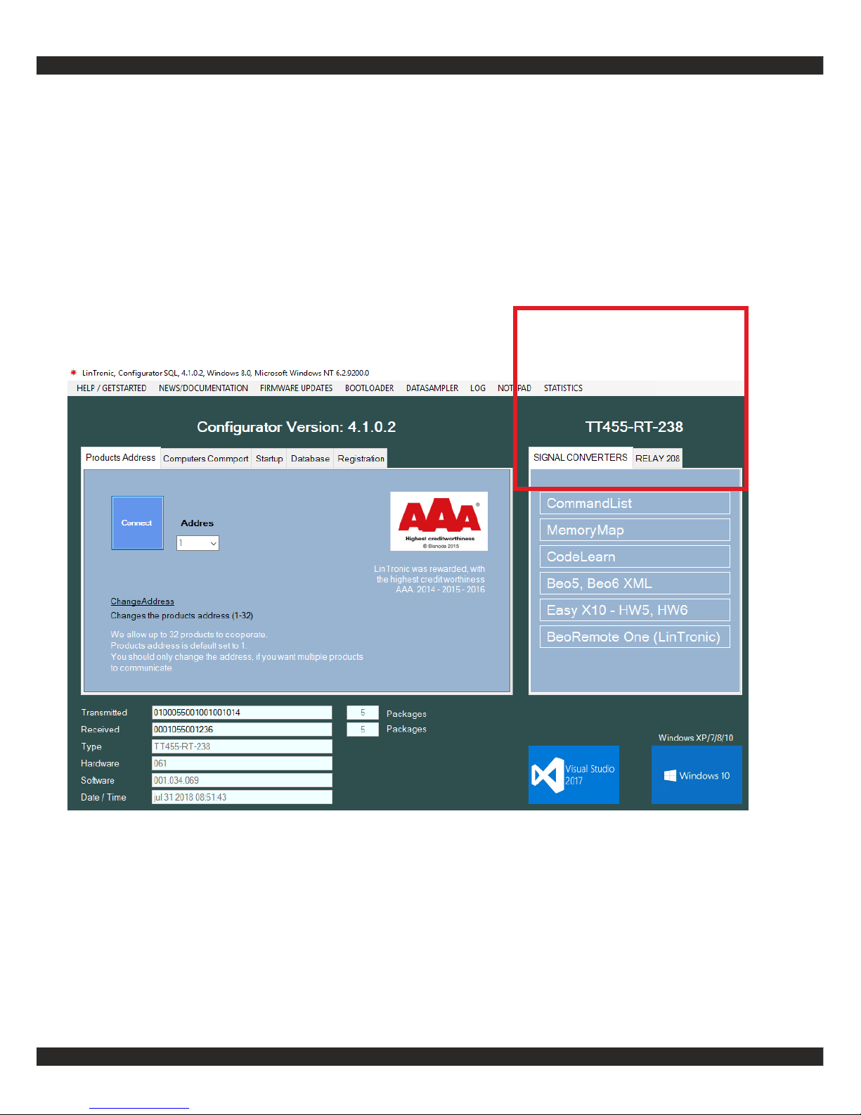
When the right comport is found there is no need to enter the Commport section again. The program
will/should remember the settings next time you start up.
Up to 32 products may work together in an industrial long-range 2-wire RS485 network.
If your product is still not detected:
- check that power supply is connected and set for 12 volt
- Products blinks for 2 seconds when power is applied
- If you use our USB-RS232 ComCab-002/003 cable, did you install the driver ?
- A driver update might be required.
Still no luck ? Contact LinTronic for OnlineSupport.
CONNECT
Product detected
Page 15

http://lintronic.dk
Step 2 - CommandList
THIS IS WHERE YOU TEST COMMANDS/ACTIONS SO
YOU KNOW THEY WORK. THEN GOTO MEMORY MAP.
Update your database to get the latest commands uploaded
by other users.
Select a product closest to one of your products.
If you can find another typenumber than yours it will most
likely work.
- take it easy - start by testing a few commands
- start with a TV or a CD player
- test play, stop, power or eject
When you know how to handle a few commands you are
ready to move on - as everything is done exactly the
same way.
Mark a product as Favorite if you want to use it a
configuration project.
NEVER UPLOAD COMMANDS UNLESS YOU
HAVE TESTED THEM IN A PROJECT AND THEY WORK.
OTHERS USERS DEPEND ON YOU.
Page 16
http://lintronic.dk
Get started
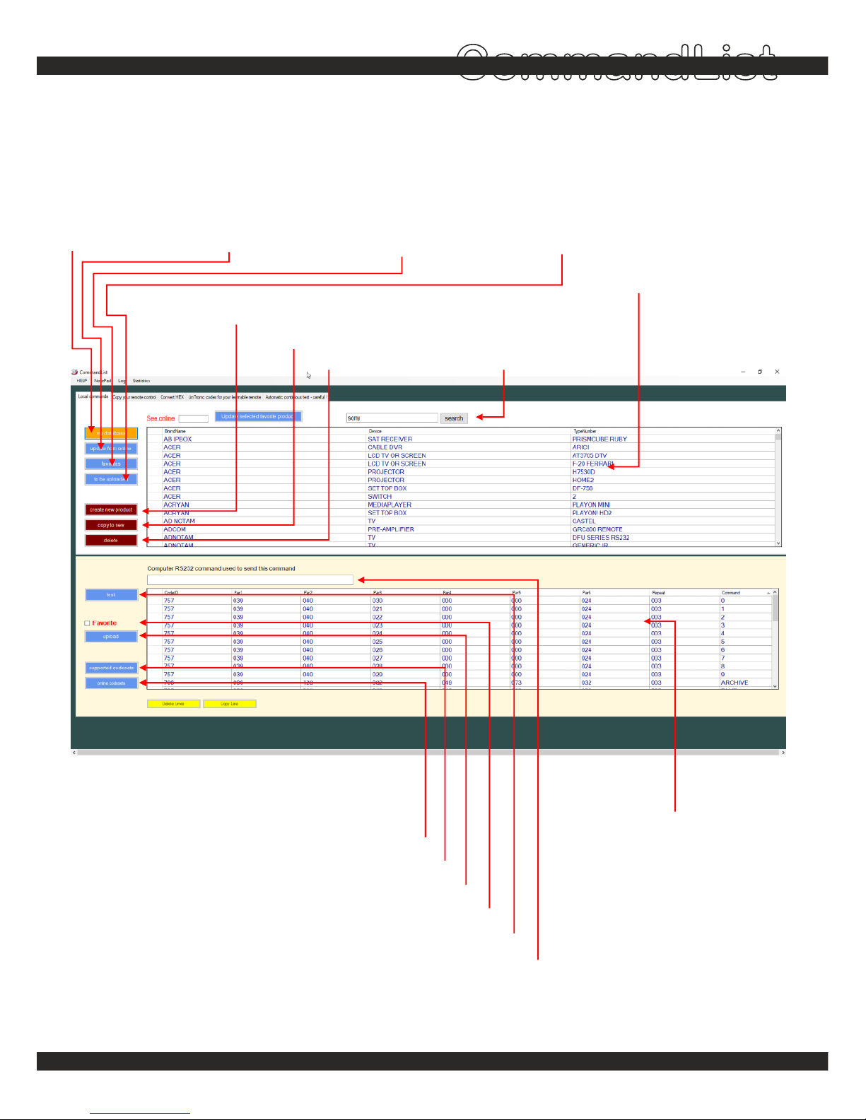
CommandList
my database
- shows your products
update from online
- downloads new products
favorites
- your projects products
to be uploaded
- your new products
create new product
copy to new
delete
products
products commands
PRODUCTS
COMMANDS / ACTIONS
online codesets
codesets supported by your product
upload to shared database AFTER you have tested they work
Setting product to favorite, will allow you to add it to your projects
search
- in brandname
- in device
- in typenumber
instructs your product to send the selected IR command
when selected IR command is tested, this shows the command you can send from your homeautomation software
Page 17
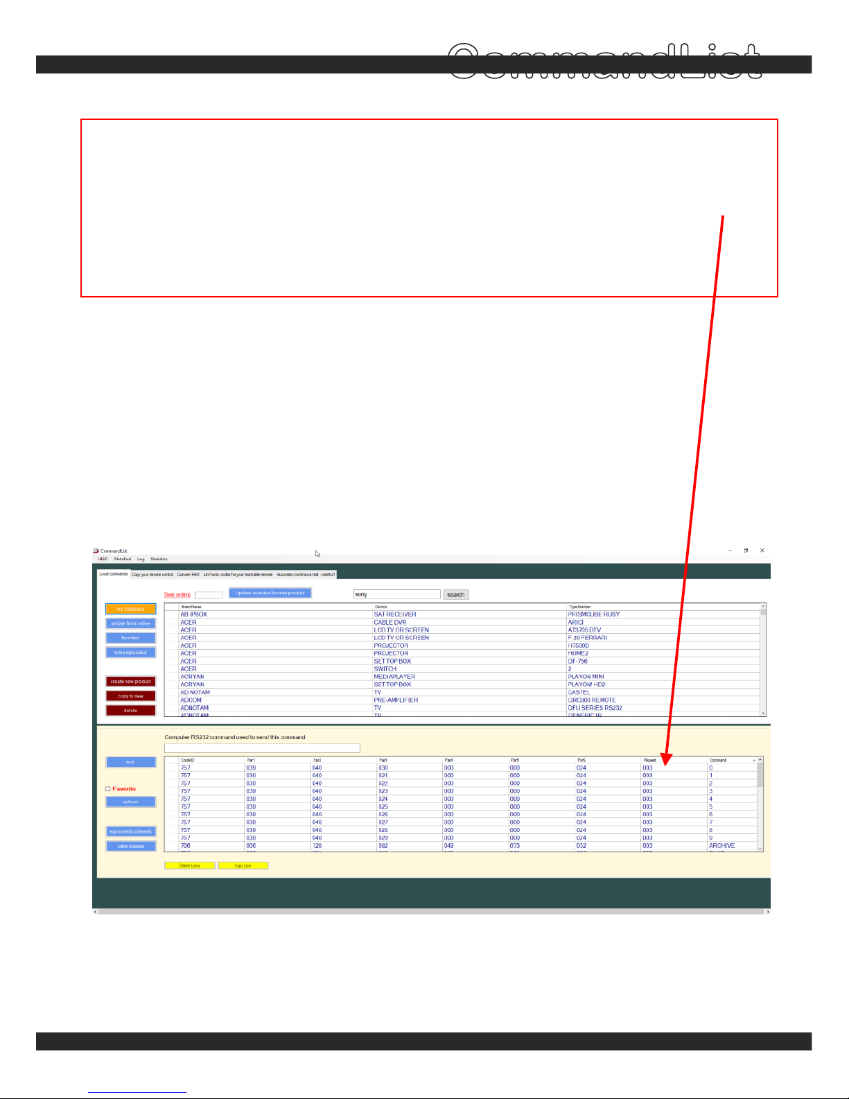
If the product performs the same command three times when tested, then adjust repeatnumber
down to 1 (001 - the range is 000 to 255).
If you can use the commands from this product, but your product holds a different typenumber,
then please copy the product into a new product and change the typenumber.
See the complete CommandList manual for more details - and how to copy commands
from your own remote control.
http://lintronic.dk
Get started
CommandList
Read this
REPEATNUMBER
TYPENUMBER
Page 18

http://lintronic.dk
Step 3 - MEMORY MAP
THIS IS WHERE YOU CREATE A PROJECT HOLDING
YOUR CONFIGURATION.
SPECIFY MODE/TRIGGER - SELECT RELATED ACTION.
THAT’S IT.
If you use a B&O remote, then insert the B&O receiver and
use the remote to set MODE and TRIGGER.
START SIMPLE !
Start by controlling a CD player (play, stop, eject) or
a TV (power on/off, channels, volume).
When you know how this works - you can virtually do all.
Get started
Page 19
http://lintronic.dk
Get started
TT-IR-8087030
IR
Buttons
Included
LIGHT
RADIO
TV
CD
DVD
SA
T
VT
APE
RECORD
ATAPE
9
8
7
6
5
4
3
2
1
MENU
0
TEXT
GO
EXIT
LIST
STOP
>
>
BAN
G & O
LUFSEN
>
>
>
>
>
>
Out2
Power
RS232
Input Out1
BUTTONS
INFRARED
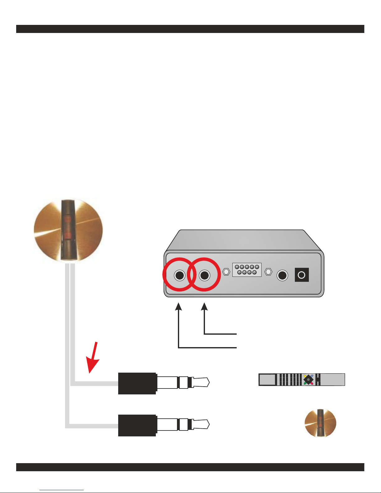
If you want to use a B&O remote
as trigger:
See manual for the TT-IR-8087030 IR receiver:
http://lintronic.dk/AppNote_TTIR8087030.pdf
STEREO-EXT-10 (extra)
TRIGGER: B&O
TT455-RT-238
Page 20
http://lintronic.dk
Get started
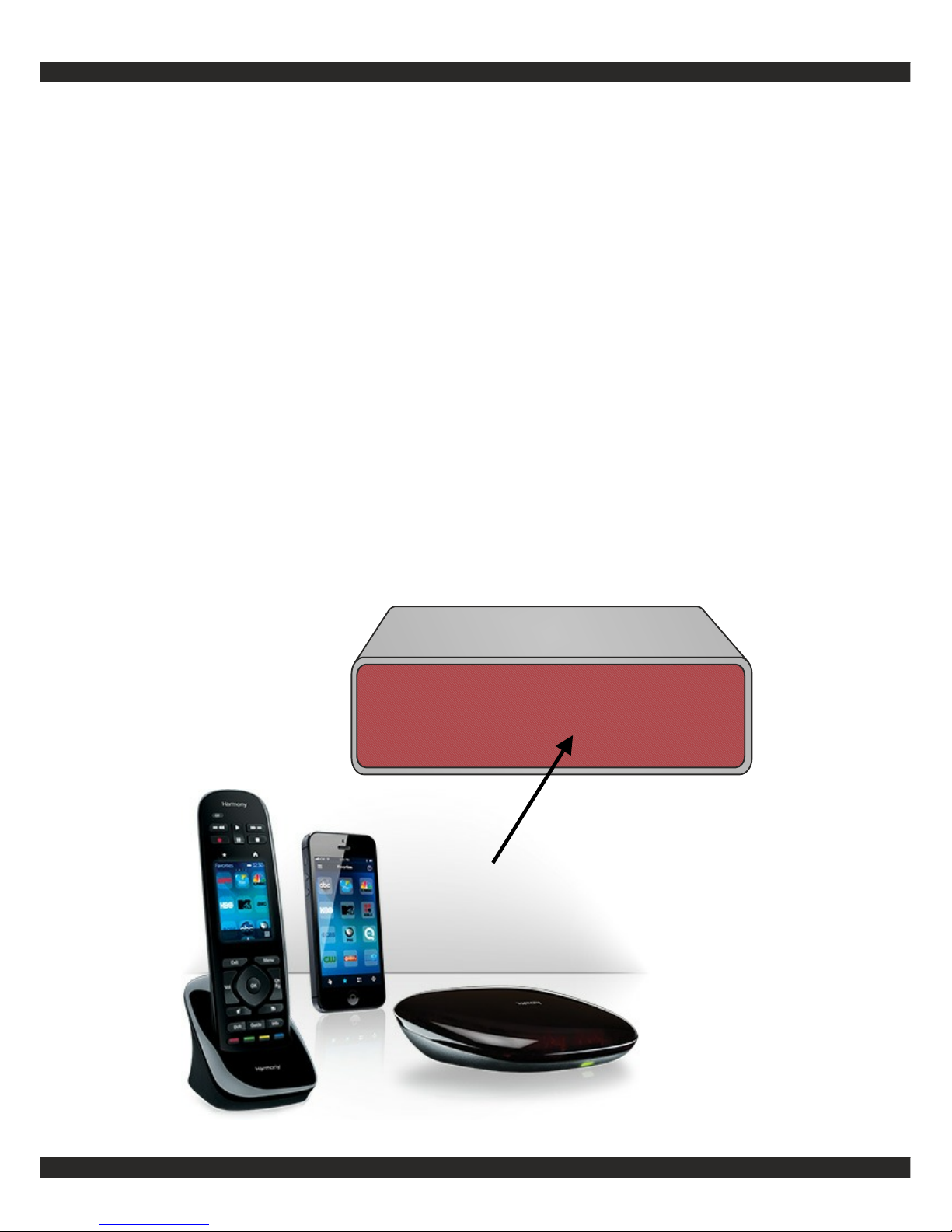
If you want to use a remote control
sending out LinTronic codes:
For easy configuration, choose LinTronic (codeset 745)
as trigger and operate the remote.
Point the remote at the front of the TT455-RT-238 and
operate the keys to set Mode and Trigger.
LogiTech Smart can be recommended allowing control
from your smartphone.
TRIGGER: LINTRONIC
Page 21
http://lintronic.dk
Get started
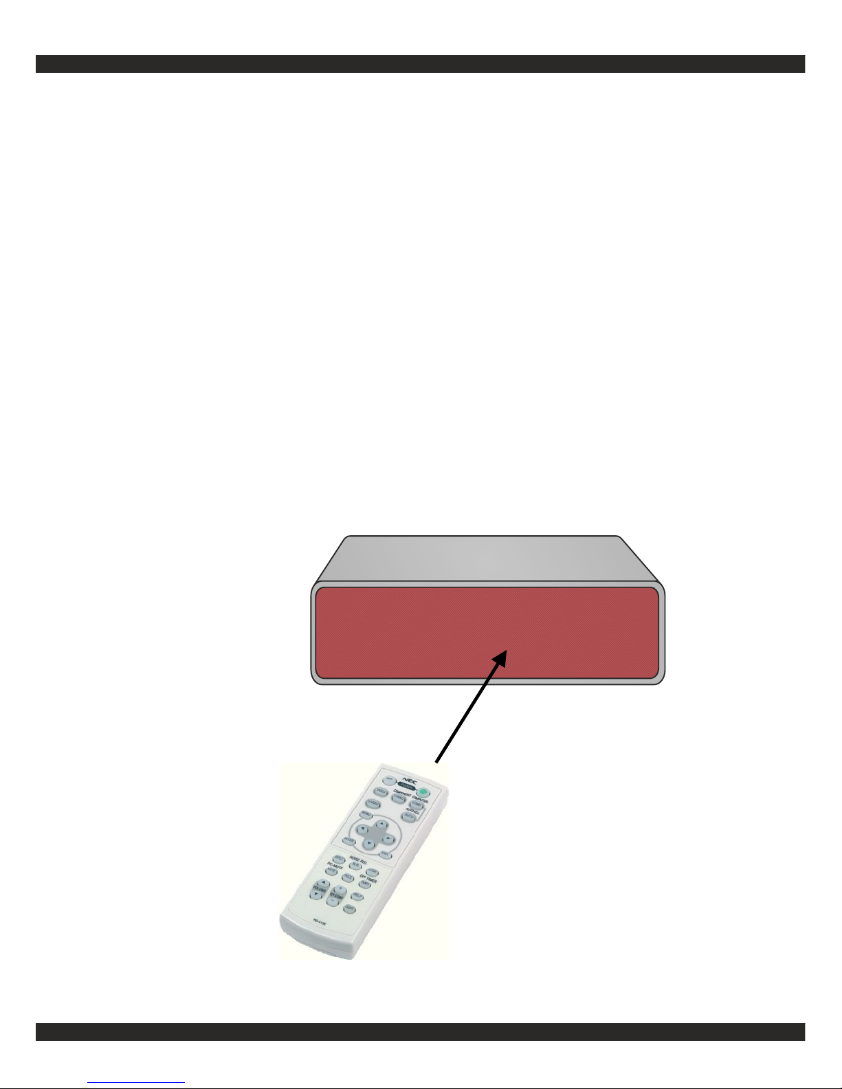
If you want to use a NEC code
based remote as trigger:
For easy configuration, choose NEC (codeset 713/716)
as trigger and operate the remote.
Point the remote at the front of the TT455-RT-238 and
operate the keys to set Mode and Trigger.
TRIGGER: NEC
Page 22
http://lintronic.dk
Get started
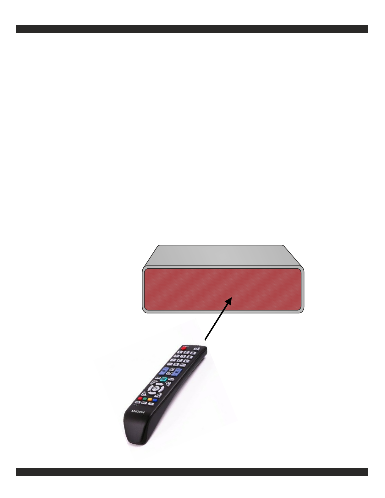
If you want to use a SAMSUNG
code based remote as trigger:
For easy configuration, choose SAMSUNG (codeset 753)
as trigger and operate the remote.
Point the remote at the front of the TT455-RT-238 and
operate the keys to set Mode and Trigger.
TRIGGER:SAMSUNG
Page 23
http://lintronic.dk
Get started
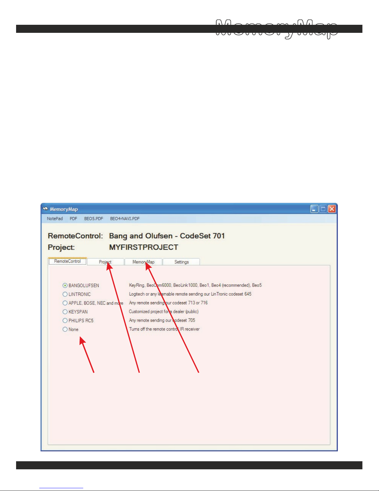
MEMORY MAP
This is where you specify how your Triggers activate the Actions.
TRIGGER ( Incoming signals )
ACTION ( Outgoing signals )
A Trigger can for example be:
- an InfraRed (IR) signal from your remote control (Apple, Bang&Olufsen, Bose, NEC etc.)
- the activation/release of a switch or sensor connected to one of the two digital inputs
- an RS232 command from a computer or another type of controller
An Action is for example:
- one or more InfraRed (IR) signals for your products (audio/video, light, curtains, aircon etc.)
- an RS232/RS485 command for your computer, projector, lcd/plasma screen,light, etc.
- a LinTronic bus-command for individual or broadcast control for up to 32 TT455-T-238's
Select remote Select project Configuration
MemoryMap
Page 24
http://lintronic.dk
Get started
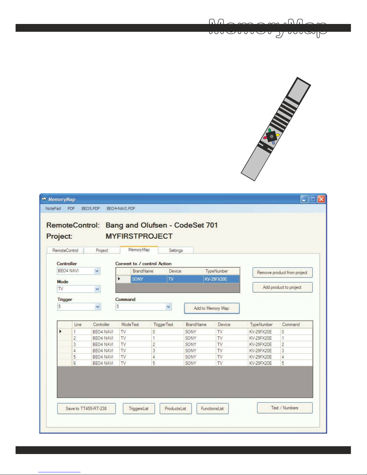
MEMORY MAP
In this example we assume you use a Beo4 NAVI (recommended) to set the
Mode/Trigger.
1. Point the BEO4 at the TT455-RT-238's external receiver or use
the mouse to select: Mode TV - Trigger 0
2. Add Sony TV KV-F29FX20E to the project.
3. Select the product.
4. Select the command you want related to TV 0
5. Add to Memory Map
- Continue step 4 and 5 with more commands
6. Save to TT455-RT-238
You may now remove the TT455-RT-238 from the computer
LIGHT
RADIO
TV
CD
DVD
SA
T
VT
APE
RECORD
AT
APE
9
8
7
6
5
4
3
2
1
MENU
0
TEXT
GO
EXIT
LIST
STOP
>
>
BAN
G &O
LU
FS
EN
>
>
>>
>>
1
2
1
1
3
4
5
6
MemoryMap
Page 25
http://lintronic.dk
Get started
MemoryMap
Ports (InfraRed)
IR TRANSMITTER
IR FRONT BOOSTER
IR LOW-POWER 1
IR LOW-POWER 2
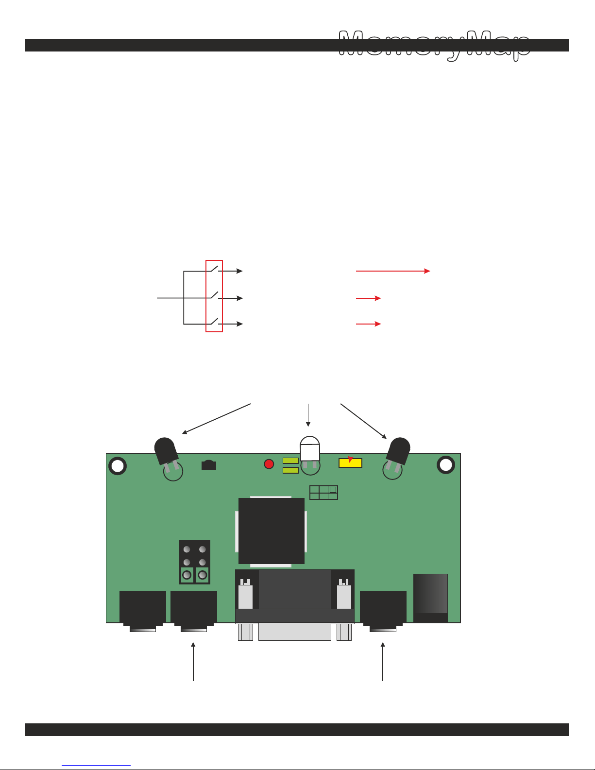
For transmission of infrared signals, the TT455-RT-238 includes a:
PROGRAMMABLE 3-CHANNEL IR DISTRIBUTOR
This means you can specify where you want the infrared signal to be transmitted:
On the low-power output 1 and/or on the low-power output 2 and/or on the high-power front
booster.
The high-power wide-angle dual-band front IR booster, will reach most if not all products in the
same room. If you place the TT455-RT-238 on top of a cabinet, then the low-power outputs can
reach products inside the cabinet, by means of the low-power emitters TT-IT-ET02.
50% or 100%
HIGH-POWER WIDE-ANGLE DUAL-BAND
IR FRONT BOOSTER
IR LOW-POWER OUTPUT 2 IR LOW-POWER OUTPUT 1
Page 26
http://lintronic.dk
Get started
MemoryMap
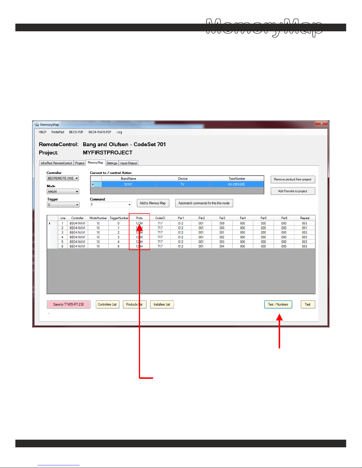
You can specify on which ports you want the IR signal to be transmitted.
You can instruct the signal to be transmitted on any of the two low-power outputs,
or on the high-power front booster - or any combination of the three.
1. Click here to enter NUMBERS mode
2. Click here to adjust ports
Options are:
1 = low-power port 1
2 = low-power port 2
3 = high-power front IR
H = front use 100% power
Ports (InfraRed)
Page 27
http://lintronic.dk
Get started
MemoryMap
Ports (RS232)
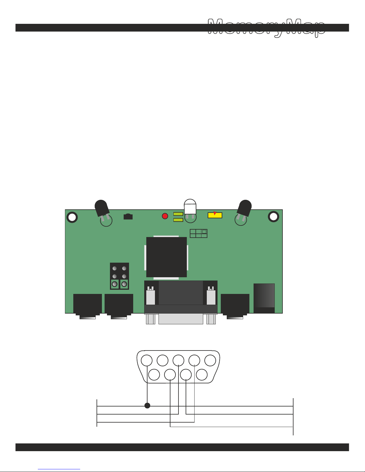
For transmission of RS232 signals, the TT455-RT-238 includes a:
PROGRAMMABLE 2-CHANNEL RS232 DISTRIBUTOR
This means you can specify where you want the RS232 signal to be transmitted:
On comport 1 (pin 7-8) or on comport 2 (pin 2-3).
You can use both RS232 ports to control your products.
The TT455-RT-238 can be placed on top of a cabinet and you can connect RS232 kables to for
example a TV, a projector, an amplifier, etc.
Comport 2 is used by the TT455-RT-238 when communicating with the computer, while being
configured. After being configured, you disconnect power to the TT455-RT-238. When
repowered the TT455-RT-238 is ready to control/monitor your RS232 product on this comport.
5 4 3 2 1
9 8 7 6
Gnd
Rx (in)
Tx (out)
Gnd
Rx (in)
Tx (out)
RS232 PORT 2
RS232 PORT 1
Page 28
http://lintronic.dk
Get started
MemoryMap
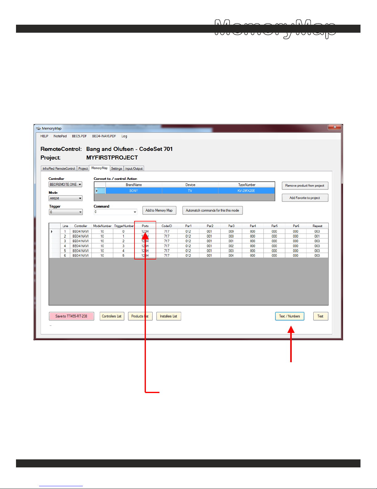
You can specify on which ports you want the RS232 signal to be transmitted.
You can instruct the signal to be transmitted on any of the two RS232 comports,
but only on one of them.
1. Click here to enter NUMBERS mode
2. Click here to adjust ports
Options are:
1 = comport 1 (pin 7-8)
2 = comport 2 (pin 2-3)
Ports (RS232)
Page 29
http://lintronic.dk
Get started
Step 4 - MyScore
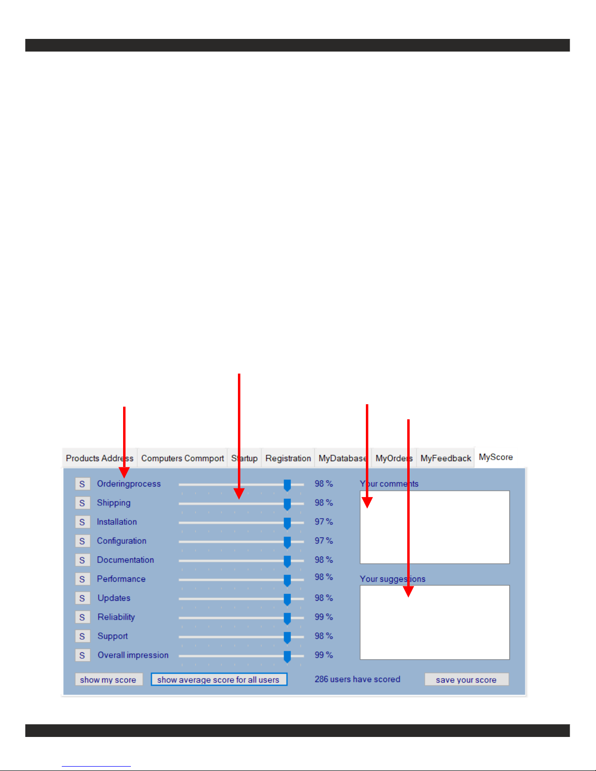
The tab MyScore allows you to let us know what you think of our products and
services.
1) Set the markers for a value from 10% to 100% for each area.
2) Enter your comments and suggestions.
3) Save your score.
You will be asked whether you want to send your feedback to LinTronic.
You can at any time read your score, change it and save again.
Set 10% for worst score and 100% for best score - for each area.
Areas Enter your comments
Enter your suggestions
MyScore
Page 30
http://lintronic.dk
Get started
MyScore
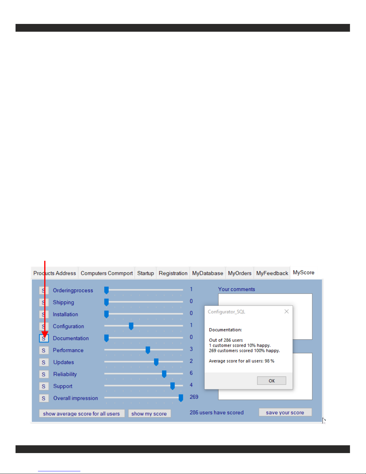
Click the S for each area, to see how other LinTronic users scored the particular area.
For example, click the S left for the Documentation label, which will show you how other
users likes the documentation.
We evaluate the scorings to determine how we can improve in all areas.
In this case:
1 user scored 10%
1 user scored 40%
3 users scored 60%
2 users scored 70%
6 users scored 80%
4 users scored 90%
269 users scored 100%.
The aveage score for the documentation, for 269 users out of 286 is 98%.
In other words: 94% of the users find the documentation 100% satisfactory.
Page 31
http://lintronic.dk
Get started
MyScore
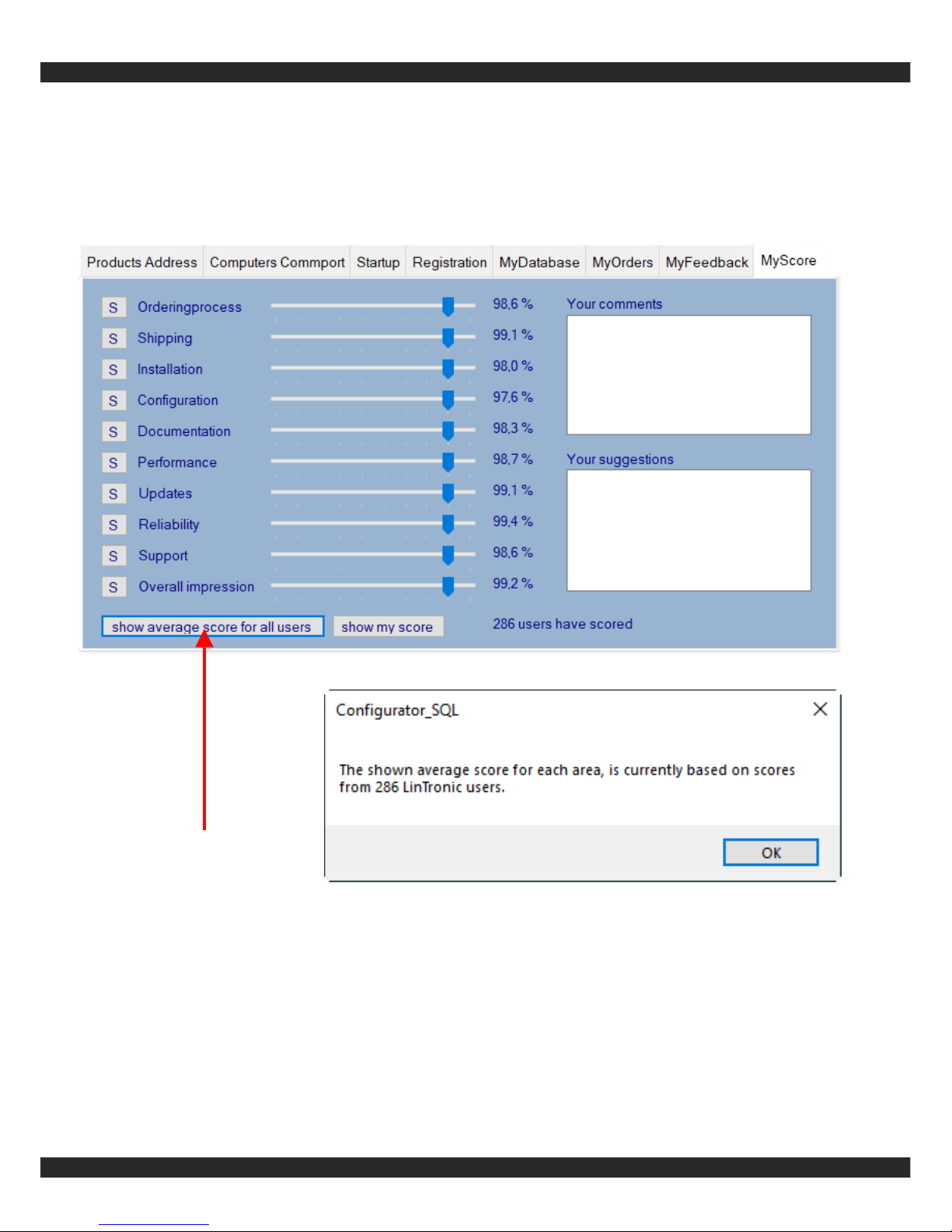
Click to see the average score, for all users for all areas:
Page 32
http://lintronic.dk
Get started
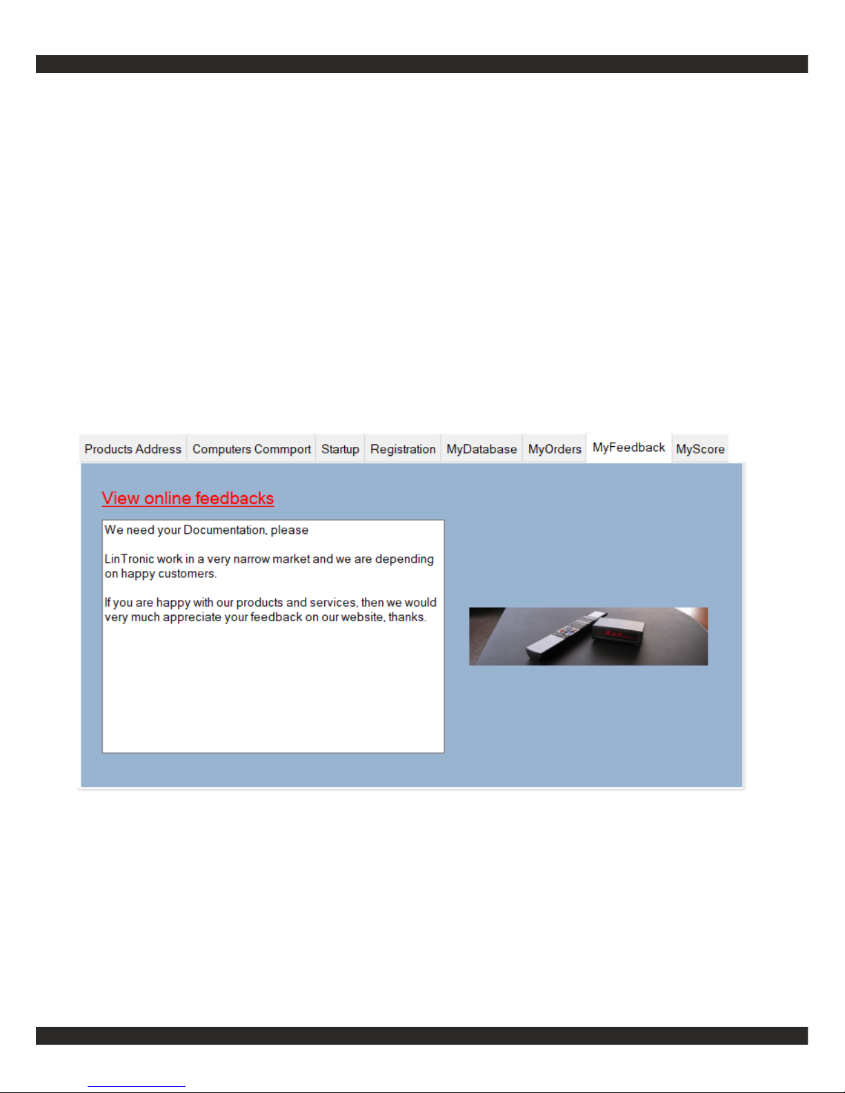
If you have contributed to our online fedback page, then you get a simplified copy
in this folder.
In order to help us with your feedback goto: http://lintronic.dk/feedback.aspx
MyFeedback
Step 5 - MyFeedback
Page 33
http://lintronic.dk
Get started
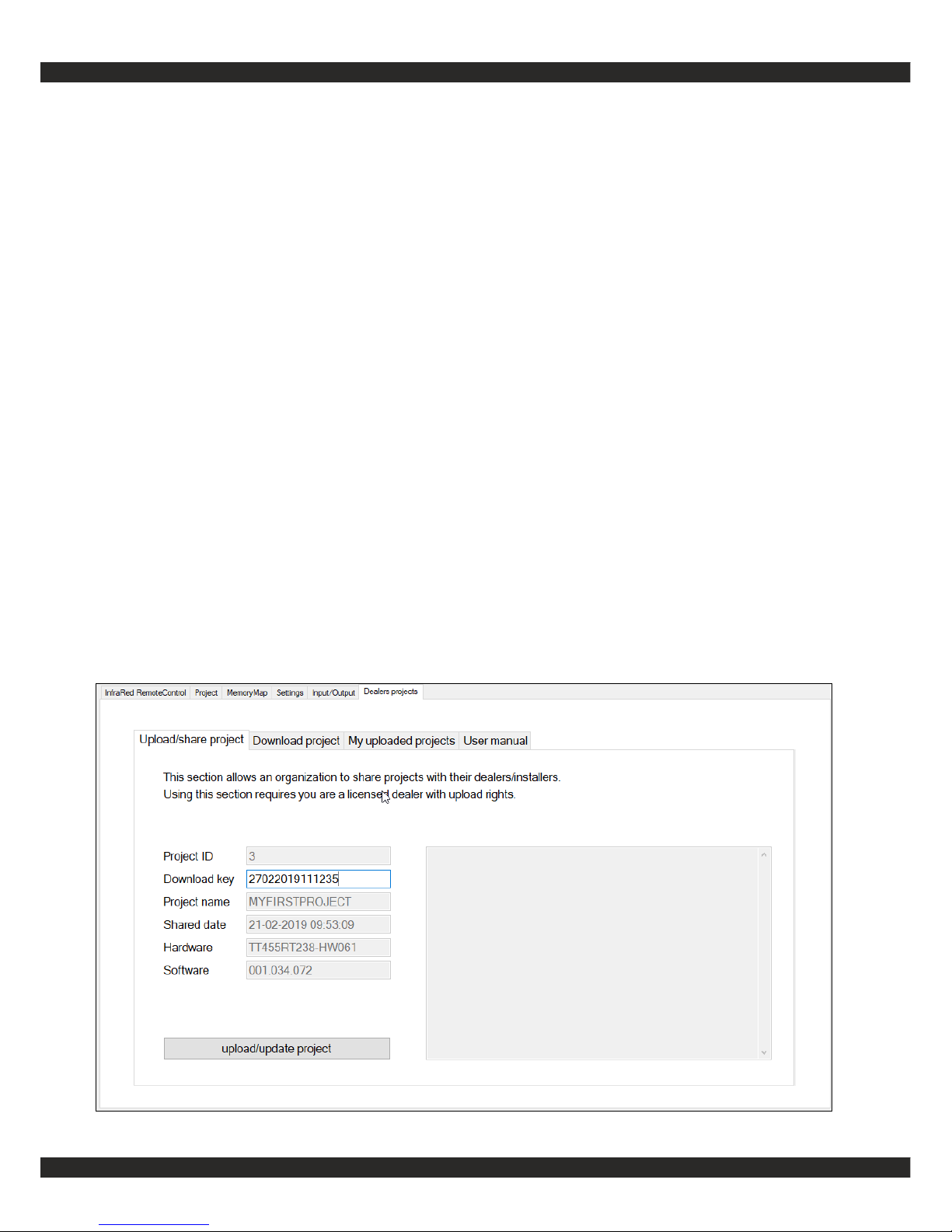
This new section, allows dealers to share Memory Map projects in the cloud.
Projects can be uploaded (by administrator) or downloaded (by dealers).
Administrator can change each project and upload new/revised version.
In order to download a project as a dealer, you need to know the Project ID
and the Download key.
To ensure everything works as expected at customer/dealer site, downloaded
projects cannot be edited.
If this could be intersting for your organisation, please contact LinTronic.
MyFeedback
Step 6 - Dealers projects
Page 34

http://lintronic.dk
Get started
Do not forget to study
the technical manual
in order to get the
most out of your
TT455-RT-238.
[end of document]
 Loading...