


NTI AG / LinMot Dok-Nr. 0185-0004-E_2V2_IG_Linear_Motors_P10-70
Installation Guide
Linear Motors
ENG
P10-70 / P10-70-D01/02/03

Installation Guide Linear Motors ENG
Page 2 / 41 P10-70 / P10-70-D01/02/03 NTI AG / LinMot
Content
1 General information ................................................................................................................................. 4
1.1 Introduction ........................................................................................................................................ 4
1.2 Symbolerklärung ................................................................................................................................ 4
1.3 Qualified personnel ............................................................................................................................ 4
1.4 Liability ............................................................................................................................................... 4
1.5 Copyright ............................................................................................................................................ 4
2 Safety instructions ................................................................................................................................... 5
3 Installation instructions ........................................................................................................................... 7
3.1 Operating conditions .......................................................................................................................... 7
3.2 Instructions for installing the linear motor .......................................................................................... 7
3.3 Mounting the stator ............................................................................................................................ 8
3.4 Mounting the payload to the slider ..................................................................................................... 8
3.5 "Moving slider" installation ............................................................................................................... 10
3.6 "Moving stator" installation ............................................................................................................... 10
3.6.1 Assembling instruction ................................................................................................................. 11
3.7 Minimum distance from slider .......................................................................................................... 12
3.7.1 Minimum distance from slider to slider ........................................................................................ 12
3.7.2 Minimum distance from slider to metallic parts ............................................................................ 13
4 Fluid cooling ........................................................................................................................................... 13
4.1 Design of water cooling ................................................................................................................... 13
4.1.1 Determination of the max. possible amount of cont. power dissipation Pv_Max ........................ 14
4.1.2 Determination of water flow Q ..................................................................................................... 14
4.1.3 Determination of water pressure p ........................................................................................... 15
4.2 Corrosion protection ........................................................................................................................ 15
4.3 Mounting .......................................................................................................................................... 15
5 Motor Cable ............................................................................................................................................. 16
5.1 Technical Data ................................................................................................................................. 16
5.2 Options of power cable .................................................................................................................... 17
5.2.1 Stator Series P10-70 ................................................................................................................... 17
5.2.2 Stator Series P10-70-D01 / D02 .................................................................................................. 17
5.2.3 Stator Series P10-70-D03 ............................................................................................................ 17
5.3 Options of sensor cables ................................................................................................................. 17
5.3.1 Stator Series P10-70 ................................................................................................................... 17
5.3.2 Stator Series P10-70-D01 / D02 .................................................................................................. 17
5.3.3 Stator Series P10-70-D03 ............................................................................................................ 17
5.4 Attaching the cable shielding .......................................................................................................... 18
5.5 Rotatability of motor connectors ...................................................................................................... 18
6 Accessories ............................................................................................................................................ 19
6.1 Wiper with exchangeable end piece ................................................................................................ 19
6.2 Wiper with lubricant depot ............................................................................................................... 20
6.3 Bearing kit with exchangeable end pieces ...................................................................................... 21
6.3.1 Overview ...................................................................................................................................... 21

Installation Guide Linear Motors ENG
NTI AG / LinMot P10-70 / P10-70-D01/02/03 Page 3 / 41
6.3.2 Mounting ...................................................................................................................................... 22
6.4 Bearing kit with lubricant depot ........................................................................................................ 23
6.4.1 Overview ...................................................................................................................................... 23
6.4.2 Mounting ...................................................................................................................................... 24
6.5 Mounting flanges ............................................................................................................................. 25
6.6 Fan kits for flanges .......................................................................................................................... 27
6.7 Fluid cooling flanges ........................................................................................................................ 28
6.8 Slider mounting kits ......................................................................................................................... 30
6.8.1 Fixed bearing ............................................................................................................................... 30
6.8.2 Floating bearing ........................................................................................................................... 31
6.8.3 Complete mounting kit ................................................................................................................. 31
7 Maintenance and test instructions ....................................................................................................... 32
7.1 Stator connector assignment ........................................................................................................... 32
7.1.1 Power Connector ......................................................................................................................... 32
7.1.2 Sensor Connector ........................................................................................................................ 33
7.2 Stator checking ................................................................................................................................ 34
7.3 Maintenance of linear motors .......................................................................................................... 35
7.3.1 Mounting ...................................................................................................................................... 35
7.3.2 Inspection..................................................................................................................................... 35
7.3.3 Cleaning ....................................................................................................................................... 36
7.3.4 Cleaning agent / Lubricant ........................................................................................................... 36
8 Storage, transport, installation altitude ............................................................................................... 37
9 Dimensions ............................................................................................................................................. 37
9.1 Stator ............................................................................................................................................... 37
9.1.1 PS10-70x80 ................................................................................................................................. 37
9.1.2 PS10-70x160 ............................................................................................................................... 37
9.1.3 PS10-70x240 ............................................................................................................................... 37
9.1.4 PS10-70x320 ............................................................................................................................... 38
9.1.5 PS10-70x400 ............................................................................................................................... 38
9.2 Slider ................................................................................................................................................ 38
10 UL Certificate ..................................................................................................................................... 39
11 Declaration of Conformity and CE-marking .................................................................................... 40

Installation Guide Linear Motors ENG
Page 4 / 41 P10-70 / P10-70-D01/02/03 NTI AG / LinMot
1 General information
1.1 Introduction
This manual includes instructions for the assembly, installation, maintenance, transport, and storage of linear
motors. The document is intended for electricians, mechanics, service technicians, and warehouse staff.
Be sure to observe the general safety instructions as well as those in each chapter at all times.
Keep this manual accessible to the assigned staff.
1.2 Symbolerklärung
Triangular warning symbols warn against a danger.
Round command symbols tell what to do.
1.3 Qualified personnel
All work such as transport, installation, commissioning and service is only allowed to be carried out by
qualified personnel. Qualified personnel in the sense of the safety instructions in this documentation are
persons who are familiar with the transport, installation, assembly, commissioning and operation of the
product and who have the appropriate qualifications.
This manual must be read carefully before transport, installation, commissioning, service and all safetyrelated information must be adhered to.
1.4 Liability
NTI AG (as manufacturer of LinMot linear motors and MagSpring products) excludes all liability for damages
and expenses caused by incorrect use of the products. This also applies to false applications, which are
caused by NTI AG's own data and notes, for example in the course of sales, support or application activities.
It is the sole responsibility of the user to check the information and information provided by NTI AG regarding
their safety-relevant correctness. In addition, the entire responsibility for safety-related product functionality
lies exclusively with the user.Product warranties are void if products are used with stators, sliders, servo
drives or cables not manufactured by NTI AG unless such use was specifically approved by NTI AG.
NTI AG’s warranty is limited to repair or replacement as stated in our standard warranty policy as described
in our "terms and conditions" previously supplied to the purchaser of our equipment (please request copy of
same if not otherwise available). Further reference is made to our general terms and conditions.
1.5 Copyright
This work is protected by copyright.
Under the copyright laws, this publication may not be reproduced or transmitted in any form, electronic or
mechanical, including photocopying, recording, microfilm, storing in an information retrieval system, not even
for training purposes, or translating, in whole or in part, without the prior written consent of NTI AG.
LinMot® is a registered trademark of NTI AG.

Installation Guide Linear Motors ENG
NTI AG / LinMot P10-70 / P10-70-D01/02/03 Page 5 / 41
2 Safety instructions
Contusions
Sliders contain neodynium magnets and have a strong attractive force.
Careless handling could cause fingers or skin to become pinched between sliders. This may
lead to contusions, bruises, and bone fractures.
When handling sliders, wear thick protective gloves and keep a minimum distance between
sliders. Refer to the "Minimum distance from slider" section for minimum distance.
Pacemaker / Implanted heart defibrillator
Sliders could affect the functioning of pacemakers and implanted heart defibrillators. For the
duration of a strong approach to a magnetic field, these devices switch into test mode and
will not function properly.
If you wear one of those devices keep the following minimum distances between the
pacemaker / defibrillator and slider:
- Min. 250 mm (10ʺ) for slider Ø 27 mm and 28 mm (PL01-27 / 28 / PL1028)
- Min. 150 mm (6ʺ) for slider Ø 19 mm and 20 mm (PL01-19 / 20)
- Min. 100 mm (4ʺ) for slider Ø 12 mm (PL01-12)
Inform others who wear these devices to comply with these minimum distances!
Caution - Risk of Electric Shock !
Before working, make sure that there are no extremely high voltages.
Fast-moving machine parts
The sliders of LinMot linear motors are fast-moving machine parts. All necessary
precautions must be taken to prevent access during operation (provide covers, guards,
etc.).
Automatic restart
The motors can start automatically under certain cricumstances!
If necessary, a corresponding warning symbol must be provided and protection against
entering the hazardous area or a suitable safe electronic disconnection must be provided!
Risk of injury due to a defect or fault
For areas where a defect or fault can result in substantial property damage or even serious
personal injury, additional external precautions must be taken or devices must be installed
to ensure safe operation even if a defect or fault occurs (eg. suitable safe electronic
disconnection, mechanical interlocks, barriers, etc.).
Magnetic field
Magnets integrated in the sliders produce a strong magnetic field. They could damage TVs,
laptops, computer hard drives, credit and ATM cards, data storage media, mechanical
watches, hearing aids, and speakers.
Keep magnets away from devices and objects that could be damaged by strong
magnetic fields.
For the above mentioned objects, keep a minimum distance as described in the
"Pacemaker / implanted defibrillator" section.
For non-anti-magnetic watches, keep the double minimum distance.

Installation Guide Linear Motors ENG
Page 6 / 41 P10-70 / P10-70-D01/02/03 NTI AG / LinMot
Combustibility
When machining magnets, the drilling dust could easily ignite.
Machining the sliders and the magnets they contain is not permitted.
Burn hazard
The sliders of LinMot motors can reach temperatures of 80 °C, which may cause burns
upon contact.
Grounding
All metal parts that are exposed to contact during any user operation or servicing and likely
to become energized shall be reliably connected to the means for grounding.
Mechanical handling
Neodymium magnets are brittle and heat-sensitive.
Machining the sliders and the magnets they contain is not permitted.
Colliding magnets could crack. Sharp splinters could be catapulted for several meters
and cause eye injury.
By machining the sliders, heat would result which demagnetises the magnets.
Slider
Linear Motor sliders must be handled with care, especially when not mounted inside the
stator. Damaging or warping the slider can result in shortened life and/or failure of the
motor. The slider is essentially a high-precision machine component consisting of
neodymium magnets and plastic materials assembled in a thin steel tube. Do not use sliders
which are already damaged on the surface (scratches, deformation, etc.). This can cause
further damage to the stator.
Effects on people
According to the current level of knowledge, magnetic fields of permanent magnets do not
have a measurable positive or negative effect on people. It is unlikely that permanent
magnets constitute a health risk, but it cannot be ruled out entirely.
For your own safety, avoid constant contact with magnets.
Store large magnets at least one meter away from your body.
Temperature resistance
Keep slider away from unshielded flame or heat.
Temperature above 120°C will cause demagnetization.

Installation Guide Linear Motors ENG
NTI AG / LinMot P10-70 / P10-70-D01/02/03 Page 7 / 41
3 Installation instructions
3.1 Operating conditions
Maximum ambient temperature limits:
10 °C…80 °C
Internal temperature sensor error occurs at:
90 °C
3.2 Instructions for installing the linear motor
Please attend to the safety instructions in chapter 2 during the assembling!
For maintenance purposes, please observe the installation instructions in chapter 7.
1. Clean the slider with a paper towel.
2. Lubrication of the slider
Sliders with a length ≤ 500 mm are inserted without
lubrication.
Sliders with a length > 500 mm are lubricated with a grease
amount of 4 g (0.14 oz) per meter, which is is about ½ of a
hazel-nut.
3. Insert the slider in the defined direction (see Assembly
step 4.).
Attention! The slider is magnetically attracted.
Installation Guide Linear Motors ENG
Page 8 / 41 P10-70 / P10-70-D01/02/03 NTI AG / LinMot
Slider front end
M10 thread + cut-in
Slider back end: M8 thread
Attention! Slider back end should not
be used for load mounting!
4. Checking the installed direction of slider
After the installation, the front end of the slider with M 10
thread and cut-in is located at the opposite side of the
stator from the cable exit.
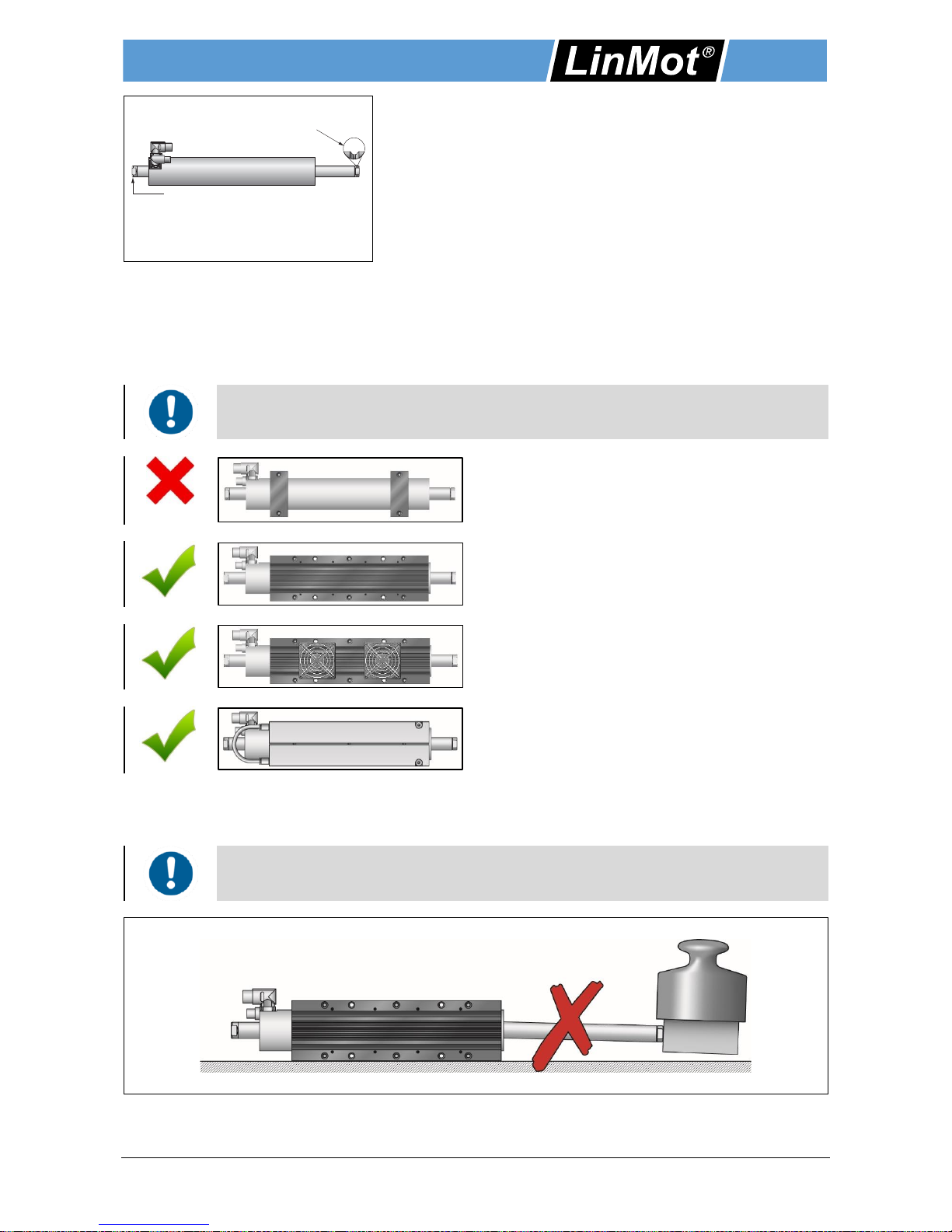
3.3 Mounting the stator
The stator is mounted by clamping. The LinMot flange (see the section 6 Accessories) or a similar flange can
be used for this purpose. Most important is a broad clamping surface in order to provide good heat
dissipation. Additionally, the cooling can be increased by a fan or liquid (water cooling), so that the
continuous power is significantly improved.
The flange clamp must not deform the stator.
Do not exceed max. torque of 16 Nm.
Incorrect mounting
Small contact area prevents cooling of the linear
motor.
Correct mounting
Better heat dissipation with the LinMot flange.
Correct mounting
Forced air cooling with LinMot fan to increase the
continuous force.
Correct mounting
Forced cooling with fluid cooling flange to increase
the continuous force. More details in chapter 4 Fluid
cooling.
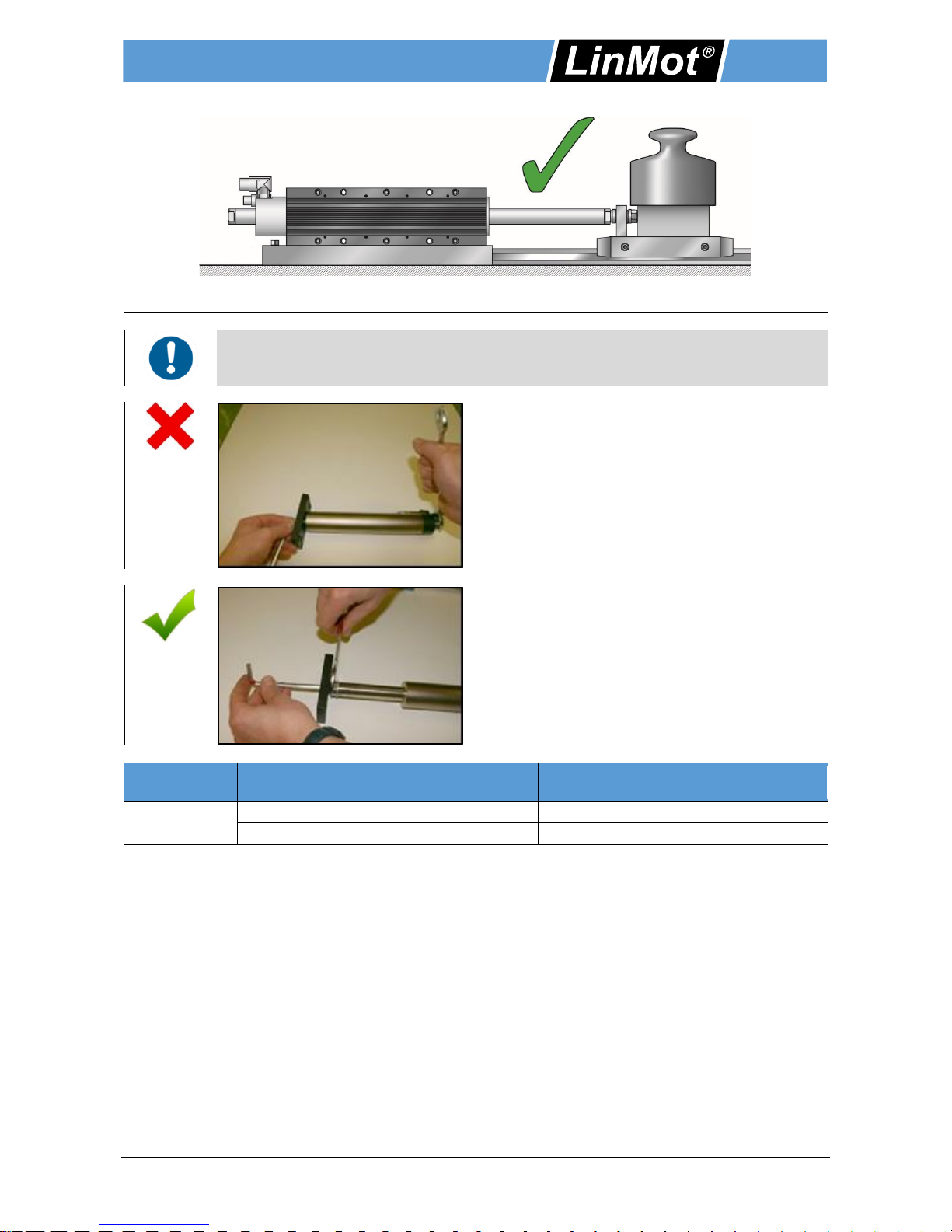
3.4 Mounting the payload to the slider
The load is mounted as a fixed bearing using spherical washers and conical seats (see the section 6).
To avoid shear force on slider and wear on stator, the payload has to be beared by a
linear guide.
Slider back end (M8 internal thread) should not be used for load mounting.
Installation Guide Linear Motors ENG
NTI AG / LinMot P10-70 / P10-70-D01/02/03 Page 9 / 41
Slider back end (M8 thread) Slider front end (M10 thread)
When attaching the load, the wrench for tightening the load must be used only on the loadfacing side of the slider. Avoid torsional stress on slider (note the following figures).
Incorrect attachment
Torsional stress on slider!
Correct attachment
Slider
Thread
Max. torque for screw
(Dry)
28 mm
M 8 (Slider back end)
22.5 Nm
M 10 (Slider front end)
42 Nm

Installation Guide Linear Motors ENG
Page 10 / 41 P10-70 / P10-70-D01/02/03 NTI AG / LinMot
3.5 "Moving slider" installation
In a "moving slider" installation, the stator is fixed and the slider is the moving part.
The load, borne by a linear guide, is attached directly to the end of the slider. In order to compensate for
misalignment, spherical axial bearings consisting of spherical washers and conical seats (see the section
Slider mounting kits) are used to connect to the load. The mounting kit of slider and an oversized hole for the
screw make it possible to adjust a radial and angle offset.
Mounted payload with radial and angle offset.
3.6 "Moving stator" installation
In "moving stator" applications, the slider is fixed and the stator is the moving part.
The load is attached to the stator, which is mounted on a linear guide. In order to avoid an overconstrained
bearing mount and compensate for alignment errors, the slider may be mounted on one end in a fixed
bearing with a spherical axial bearing. On the opposite end, the slider is mounted in a floating bearing.
Mounting kits are available for mounting the slider (see the section Slider mounting kits).
Stator
Floating bearing
Slider front end
Spherical washer and
conical seat
Slider back end
Linear bearing
Linear guide
Stator
Slider
Spherical washer +
conical seat
Slider
back end
Linear bearing
Linear guide
Slider front end

Installation Guide Linear Motors ENG
NTI AG / LinMot P10-70 / P10-70-D01/02/03 Page 11 / 41
3.6.1 Assembling instruction
Please attend to the safety instructions in chapter 2 during the assembling!
If moving stator application is used, the minimum bending radius of the motor cable should
be adhered to. See chapter Cable, section Technical Data.
1. Mount stator to its support bearing.
2. Insert slider into stator.
3. Placing a spacer
Put a spacer (wood, plasic, aluminium with thickness 15
mm) between slider and linear guide. The spacer prevents
injuries to the hands and damage to the slider surface!
4. Installing the slider using the fixed bearing
The fixed bearing is screwed to the front end of the slider.
Important! Do not tighten the screw yet!

Installation Guide Linear Motors ENG
Page 12 / 41 P10-70 / P10-70-D01/02/03 NTI AG / LinMot
5. Mount floating bearing
Imortant!
Do not tighten the screw!
The slider is allowed to extend into the floating bearing no
more than 15 mm!
6. Move stator (back end) to the fixed end of slider, center
slider in stator and tighten the screw.
7. Move stator (front side) to the floating bearing and
tighten screws.
After the installation of the slider a safety label must be placed close to the slider.
3.7 Minimum distance from slider
3.7.1 Minimum distance from slider to slider
The sliders are made of neodymium magnets and have a strong magnetic attraction.
It must be kept a minimum distance between the sliders. This minimized the risk of bruising and secondly,
the sliders do not influence each other through their magnetic fields.

Installation Guide Linear Motors ENG
NTI AG / LinMot P10-70 / P10-70-D01/02/03 Page 13 / 41
Type of slider
PL01
PL01-20 / PL01-19
PL01-28 / PL01-27
PL10-28
PL01-12
30 mm (1.18 in)
PL01-20 / PL01-19
50 mm (1.97 in)
PL01-28 / PL01-27
80 mm (3.15 in)
PL10-28
70 mm (2.76 in)
The data are measured from slider center to slider center.
3.7.2 Minimum distance from slider to metallic parts
When installing linear motors in modules with metal parts near the slider, undesired forces can arise due to
magnetic attraction or eddy currents. These generally manifest as erratic and jerky positioning, or reduced
dynamics of the linear motor. In order to avoid this, minimum distances between the slider and any metal
parts are to be observed whenever metal materials are used nearby.
Linear
Motor
Minimum distance from slider surface
to ferromagnetic parts (iron, steel,
etc.)
Minimum distance from slider surface to
non-ferromagnetic metallic parts
(aluminum, bronze, stainless steel, etc.)
P10-70x…
20 mm
10 mm
4 Fluid cooling
The heat produced by the motor is dissipated by the liquid cooling. If the motor is operated with a liquidcooling, the continuous force value increases many times in comparison with the self-cooling.
4.1 Design of water cooling
T_Flow Flow temperature
T_Back Return temperature
∆T T_Back-T_Flow
T_Water Mean coolant temperature, Formula: (T_Flow + T_Back) / 2
Q_Water Flow
∆p Differential pressure
With the water cooling, the coolant is passed through the cooling circuit of the motor flange.
Water
p
T
Back
T
Flow
Q
Water

Installation Guide Linear Motors ENG
Page 14 / 41 P10-70 / P10-70-D01/02/03 NTI AG / LinMot
Starting from the adjusted mean coolant temperature T_Water all other parameters of the cooling circuit may
be dimensioned based on the diagrams referred to:
T_Water -> Pv_Max -> Q_Water -> p
The design is illustrated by an example in the following.
4.1.1 Determination of the max. possible amount of cont. power dissipation Pv_Max
Example
Motor: P10-70x320U
T_Water: 25 °C
-> Pv_Max: 611 W
If the temperature of the cooling liquid is chosen to be lower than the ambient
temperature, there is a risk of condensation.
When used and stored in a frost-prone area, corrosion protection (e.g. Clariant) has to
be added.
4.1.2 Determination of water flow Q
Example
Pv: 611 W
∆T_Water: 6 °C
-> Q_Water: 1.5 l / min
To achieve a very regular cooling of the motor, the max. difference between flow and return
temperature should not exceed 10 ° C.

Installation Guide Linear Motors ENG
NTI AG / LinMot P10-70 / P10-70-D01/02/03 Page 15 / 41
4.1.3 Determination of water pressure p
Example
Q_Water: 1.5 l / min
-> ∆p: 0.007 bar
The required water pressure to inject the required water flow depends on the hydraulic resistance of the
cooling circuit.
4.2 Corrosion protection
It is advised to add a corrosion protection into the cooling medium (water). A suitable agent can be, for
example, Protectogen C Aqua by Clariant. Information of the mixing ratio between the cooling medium and
the corrosion protection agent can be taken from the manufacturer's instructions.
Mixing of various corrosion protection agents is to be avoided.
Corrosion protection products must be matched to the materials of the cooling circuit
(see table of materials in the cooling circuit).
Component
Material
Flange
Aluminium
Pipe
Polyurethane
Fittings
Brass nickel plated
4.3 Mounting
M6 x 55
Max. Torque16 Nm
Flange
(Top)
Flange
(bottom)
Fitting
G 1/8“
Pipe
8 x 5 mm

Installation Guide Linear Motors ENG
Page 16 / 41 P10-70 / P10-70-D01/02/03 NTI AG / LinMot
The fluid cooling flange consists of two half-shells. In both half-shells, a channel is incorporated, in which the
cooling water can circulate in longitudinal direction. Via an external pipe connection, the channels of the two
half-shells are connected in series.
Screw the half-shells by alternately tightening of the screws, which are lying across from
each other. Thus, it can be avoided that a half-shell is borne on one side only.
5 Motor Cable
Do not connect or disconnect motor when there is power on the servo drive.
Use only original LinMot cable. Cables from other sources must be checked precisely
before commissioning.
Incorrect connections can destroy the drive and stator.
5.1 Technical Data
The motor series P10-70 use various types of cables, which are used for power supply and signal power. All
cables are high-flex cables (suitable for trailing chains) and are used for fixed and moving applications.
Power cable
Sensor cable
Type
KPS15-04
KPS15-04/04
KSS05-02/08
KSS05-02/13
KSS05-02/06
Used for
PS10-70
PS10-70-D01
PS10-70-D02
PS10-70-D03
PS10-70
PS10-70-D01
PS10-70-D02
PS10-70-D03
Minimum bending
radius for fixed
installation
50 mm
(2 in)
60 mm
(2.36 in)
50 mm
(2 in)
45 mm
(1.75 in)
60 mm
(2.36 in)
Minimum bending
radius when
moving
100 mm
(4 in)
No torsion
120 mm
(4.72 in)
No torsion
100 mm
(4 in)
No torsion
90 mm
(3.54 in)
No torsion
120 mm
(4.72 in)
No torsion
Max. Cable length
30 m (may be limited by Servo Drive)
Approval
UL / CSA
1000V
UL / CSA
1000V / 300V
UL / CSA
300V
UL / CSA 30V
UL / CSA
300V
Material
Wire
isolation: TPE
Jacket: PUR
Wire isolation:
TPE
Jacket: PUR
Wire isolation:
TPE
Jacket: PUR
Wire isolation:
PE
Jacket: PUR
Wire isolation:
PP
Jacket: PUR
Oil resistance
very good
very good
very good
very good
very good
Chemical
resistance (to
acids, alkalis,
solvents,
hydraulic fluid)
good
good
good
good
good
Outdoor durability
very good
very good
very good
very good
very good
Flammability
flame
retardant
flame
retardant
flame
retardant
flame
retardant
flame
retardant

Installation Guide Linear Motors ENG
NTI AG / LinMot P10-70 / P10-70-D01/02/03 Page 17 / 41
5.2 Options of power cable
5.2.1 Stator Series P10-70
Item
Description
Item-No.
KPS15-04-L/Q-3
Power trailing chain cable L/Q (3 m)
0150-2266
KPS15-04-L/Q-5
Power trailing chain cable L/Q (5 m)
0150-2261
KPS15-04-L/Q-8
Power trailing chain cable L/Q (8 m)
0150-2267
KPS15-04-L/Q-12
Power trailing chain cable L/Q (12 m)
0150-2268
KPS15-04-L/Q-
Special cable KPS15-04-L/Q-
0150-3388
KPS15-04-Q/Q-
Special cable KPS15-04-Q/Q-
0150-3414
5.2.2 Stator Series P10-70-D01 / D02
Item
Description
Item-No.
KPS15-04-..../Q-10
Power trailing chain cable .../Q, (10 m for D0x)
0150-2376
Special cable KPS15-04-./Q-
KPS15-04-./Q- (Custom length)
0150-3491
KPS15-04
Trailing chain cable power P10-70 (per m)
0150-2257
5.2.3 Stator Series P10-70-D03
Item
Description
Item-No.
KPS15-04/04..../Q-10
Power trailing chain cable .../Q, (10 m for D03)
0150-3654
Special cable KPS15-04/04-./Q-
KPS15-04/04-./Q- (Custom length)
0150-3579
KPS15-04/04
Trailing chain cable power P10-...-Dx3 (per m)
0150-2269
5.3 Options of sensor cables
5.3.1 Stator Series P10-70
Item
Description
Item-No.
KSS05-02/08-D15/J-3
Encoder trailing chain cable D15/J (3 m)
0150-2263
KSS05-02/08-D15/J-5
Encoder trailing chain cable D15/J (5 m)
0150-2262
KSS05-02/08-D15/J-8
Encoder trailing chain cable D15/J (8 m)
0150-2264
KSS05-02/08-D15/J-12
Encoder trailing chain cable D15/J (12 m)
0150-2265
KSS05-02/08-D15(f)-45°/J-
Special cable KSS05-02/08-D15(f)-45°/J-
0150-3389
KSS05-02/08-J/J-
Special cable KSS05-02/08-J/J-
0150-3415
5.3.2 Stator Series P10-70-D01 / D02
Item
Description
Item-No.
KSS05-02/13-./J-10
Encoder trailing chain cable .../J, (10 m for D0x)
0150-2377
Special cable KSS05-02/13-./J-
KSS05-02/13-./J- (Custom length)
0150-3492
KSS05-02/13
Trailing chain cable encoder P10-...-Dxx (per m)
0150-2259
5.3.3 Stator Series P10-70-D03
Item
Description
Item-No.
KSS05-02/06-./J-10
Encoder trailing chain cable .../J, (10 m for D03)
0150-3655
Special cable KSS05-02/06-./J-
KSS05-02/06-./J- (Custom length)
0150-3611
KSS05-02/06
Trailing chain cable encoder P10-...-Dx3 (per m)
0150-2490
Installation Guide Linear Motors ENG
Page 18 / 41 P10-70 / P10-70-D01/02/03 NTI AG / LinMot
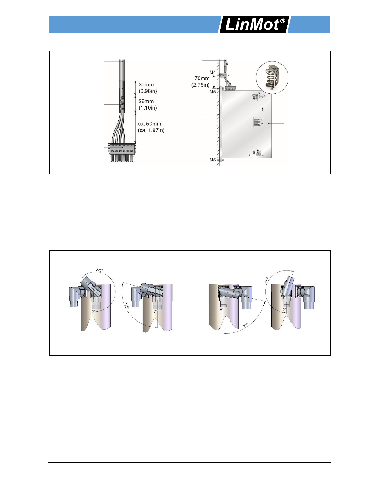
5.4 Attaching the cable shielding
The power cable is supplied with a copper shielding (see illustration above). This prevents electrical and / or
magnetic fields. The shielded part of the cable must be grounded via a connection to the back wall of the
switchboard. The shielding has to be mounted holohedral to the connection part (see scheme above). The
shield connection terminal block is offered as an accessory for power cables and must be ordered separately
(Item-No. 0150-3631) However, the kind of attaching the cable shielding generally depends on the system of
the switchboard manufacturer.
5.5 Rotatability of motor connectors
The power connector and signal connector can be rotated in both directions. (see illustration below).
Power Connector Signal Connector
Power Cable
Shrink tubing
Copper shielding
L-Connector (6 pin)
Power Cable
Conductive
mounting plate
Shield connect.
terminal block
Servo Drive
Installation Guide Linear Motors ENG
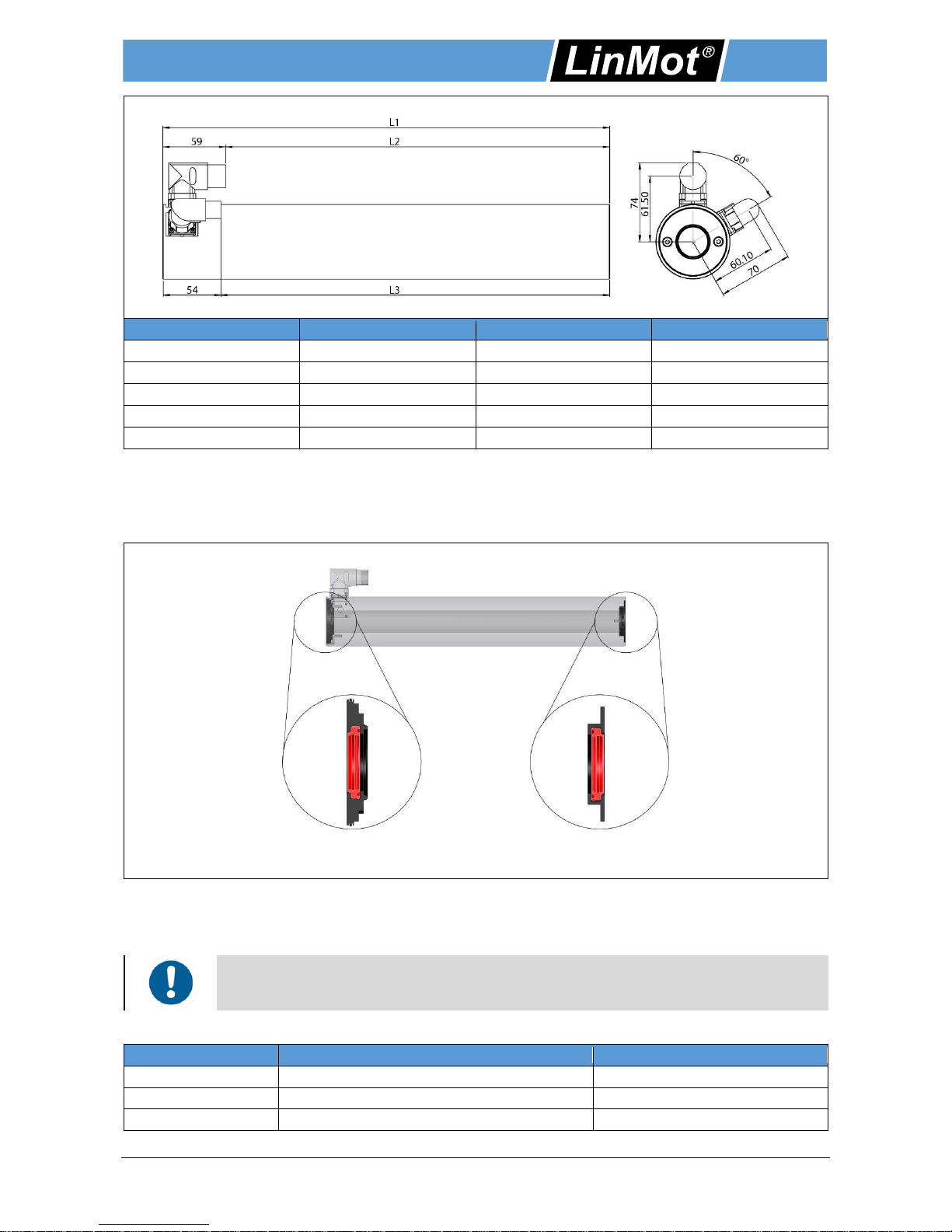
NTI AG / LinMot P10-70 / P10-70-D01/02/03 Page 19 / 41
Stator
L1 [mm / in]
L2 [mm / in]
L3 [mm / in]
PS10-70x80
180 / 7.09
121 / 4.77
125.5 / 4.94
PS10-70x160
260 / 10.24
201 / 7.92
205.6 / 8.1
PS10-70x240
340 / 13.39
281 / 11.07
285.5 / 11.24
PS10-70x320
420 / 16.54
361 / 14.22
365.5 / 14.4
PS10-70x400
500 / 19.69
441 / 17.37
445.5 / 17.55
6 Accessories
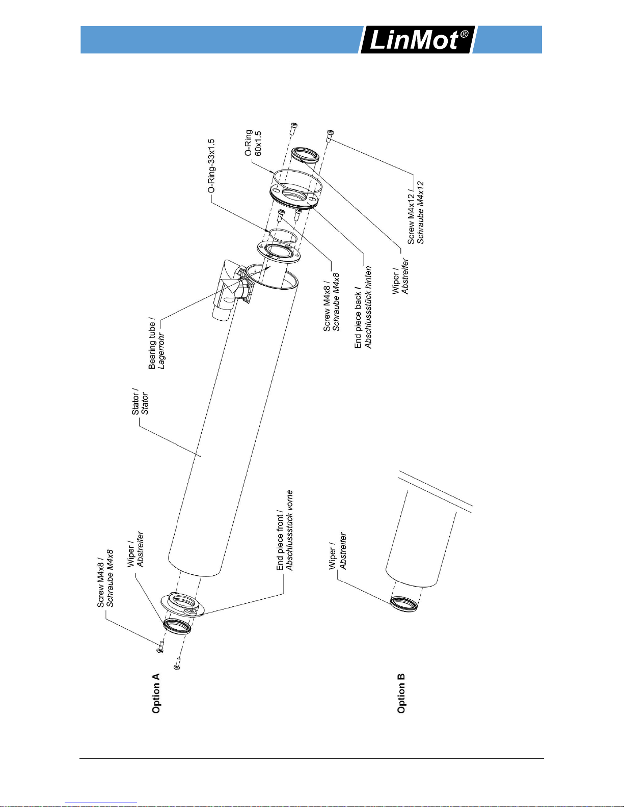
6.1 Wiper with exchangeable end piece
End piece (back) with wiper End piece (front) with wiper
The stators are equipped as standard with wipers. This simplifies maintenance and the maintenance cycles
can be extended. The wiper effects that the lubricant is dispensed metered and does not leak outside of the
stator. The lubricant is less dirty.
If the end piece (front) is firmly casted, it can not be replaced. In this case, only the wiper *
is substituted.
Ordering information
Item
Description
Item-No.
PA10-AV70
Stator end piece front side with wiper
0150-3560
PA10-AH70
Stator end piece back side with wiper
0150-3561
PAW 01-28*
Wiper for PL01-28
0150-3133

Installation Guide Linear Motors ENG
Page 20 / 41 P10-70 / P10-70-D01/02/03 NTI AG / LinMot
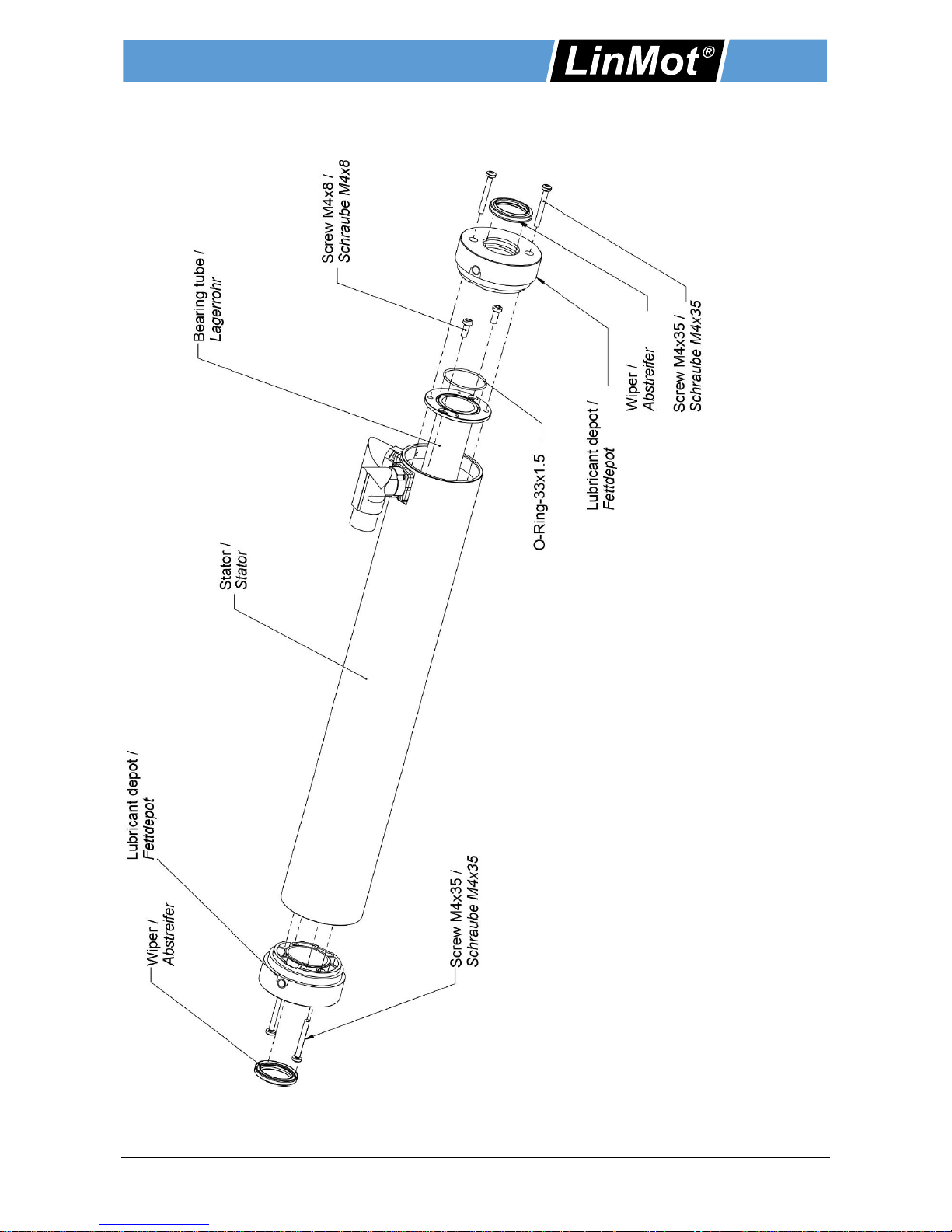
6.2 Wiper with lubricant depot
Lubricant depot with wiper
If the stators are equipped with lubricant depot, lubrication can be optimally regulated. It releases only as
much lubricant as necessary. The maintenance is simplified and maintenance cycles are extended.
If a lubricant depot is installed, the required longitudinal installation space for the stator will
be enlarged to 19 mm (rear) and 27.5 mm (front).
Lubricant depot Wiper
Material
Fettdepot: Ryton
Wiper: H-PU
Ordering information
Item
Description
Item-No.
PA10-70/28
Lubricant depot for PS10-70 with wiper + Lubricant (6 ml)
0150-3543
Installation Guide Linear Motors ENG
NTI AG / LinMot P10-70 / P10-70-D01/02/03 Page 21 / 41
6.3 Bearing kit with exchangeable end pieces
6.3.1 Overview
Installation Guide Linear Motors ENG
Page 22 / 41 P10-70 / P10-70-D01/02/03 NTI AG / LinMot
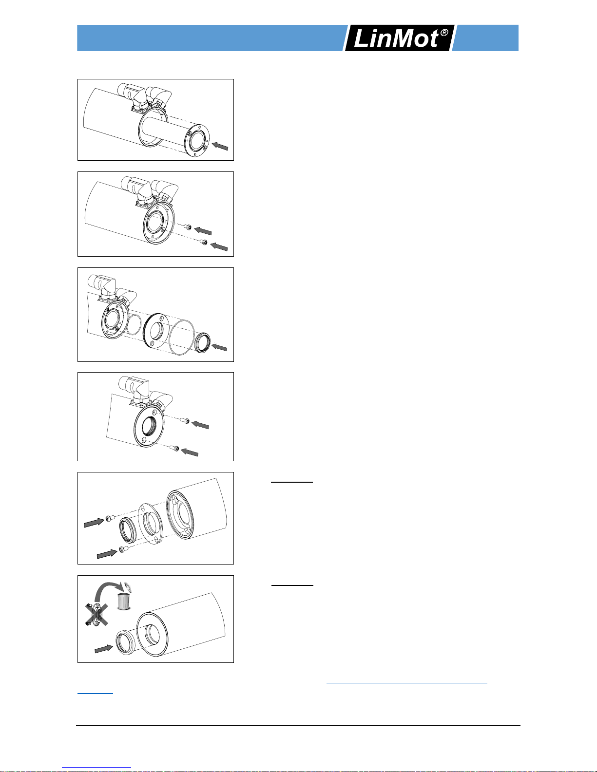
6.3.2 Mounting
1. Insert bearing tube.
Bearing tube is already lubricated with initial lubricant.
2. Tighten the fastening screws with 2.4 Nm.
Screws are already coated with threadlocker (Tuflok).
3. Assemble end piece (back).
The end piece, the seals and the wiper are assembled and
positioned on the stator.
4. Tighten the fastening screws with 2.4 Nm.
Screws are already coated with threadlocker (Tuflok).
5. Option A: Assemble end piece (front).
Assemble the end piece with the wiper and tighten it with
fastening screws (2.4 Nm torque). Screws are already
coated with threadlocker (Tuflok).
5. Option B: Exchange wiper.
Important! For motors with casted end piece only the wiper
has to be exchanged!
The bearing sets for the stators PS10-70 can be found under http://shop.linmot.com/D/linearmotoren-
zubehör/.
Installation Guide Linear Motors ENG
NTI AG / LinMot P10-70 / P10-70-D01/02/03 Page 23 / 41
6.4 Bearing kit with lubricant depot
6.4.1 Overview

Installation Guide Linear Motors ENG
Page 24 / 41 P10-70 / P10-70-D01/02/03 NTI AG / LinMot
6.4.2 Mounting
1. Insert bearing tube.
Bearing tube is already lubricated with initial lubricant.
2. Tighten the fastening screws with 2.4 Nm.
Screws are already coated with threadlocker (Tuflok).
3. Assemble lubricant depot (back).
The lubricant depot, the seal and the wiper are assembled
and positioned on the stator.
4. Tighten the fastening screws with 2.4 Nm.
Screws are already coated with threadlocker (Tuflok).
5. Insert lubricant depot (front).
Assemble the lubricant depot with the wiper and tighten it
with fastening screws (2.4 Nm torque). Screws are already
coated with threadlocker (Tuflok).
6. Lubrication
Application of the lubricant on the surface behind the used
wiper (Option A) or via the grease nipple with a hand press
(Option B).
Item
Description
Item-No.
PA10-70/28
Lubricant depot for PS10-70 with wiper + lubricant (6 ml)
Important! Mounting kit must be ordered separately.
0150-3543
360°
Option A Option B

Installation Guide Linear Motors ENG
NTI AG / LinMot P10-70 / P10-70-D01/02/03 Page 25 / 41
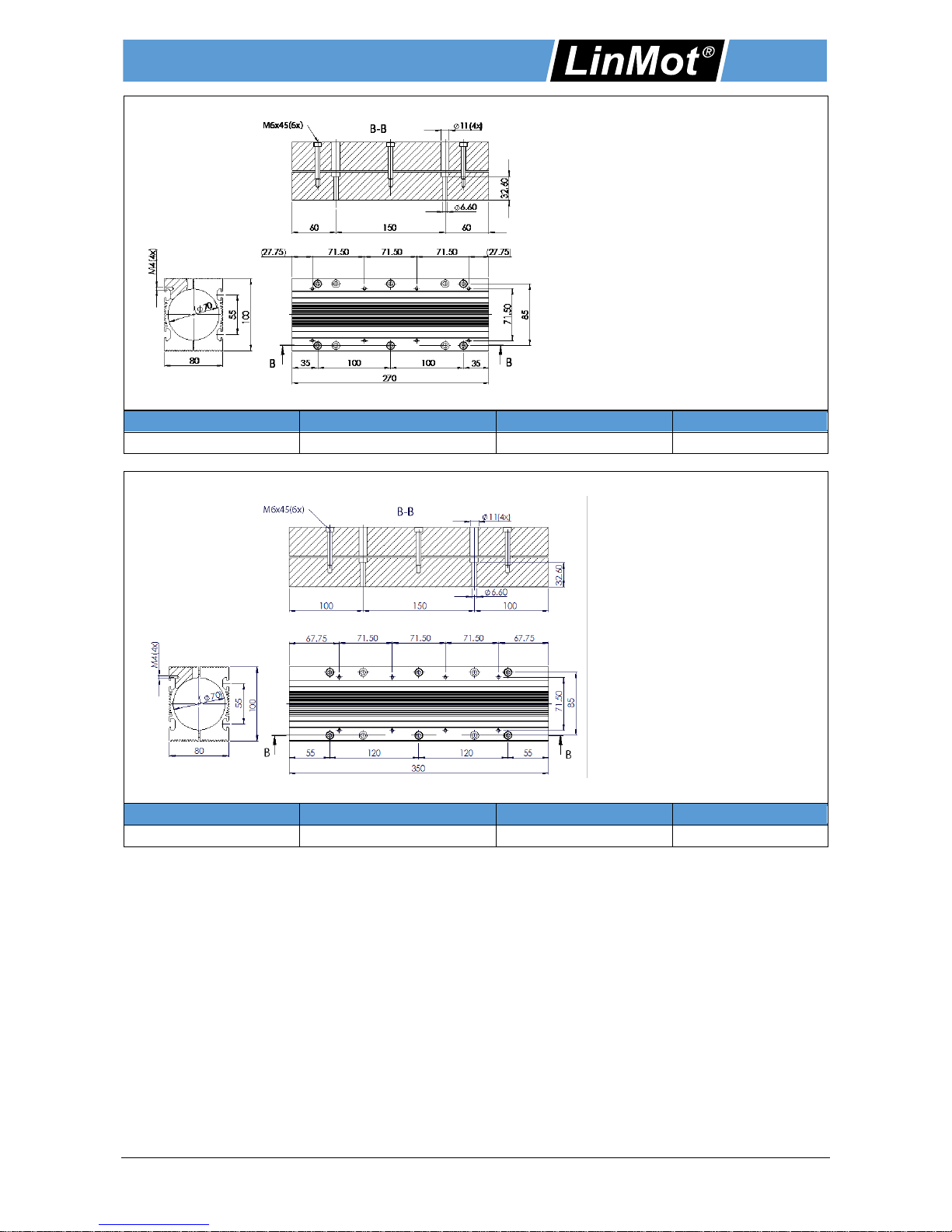
6.5 Mounting flanges
Max. Torque
Screws: 12 Nm (8.85 lbf ft)
Fan assembly
Number (Standard): 1
Number (Max.): 1
Article
Description
Weight [g / oz]
Item-No
PF10-70x110
Flange for PS10-70x80
1015 / 35.8
0150-2272
Max. Torque
Screws: 12 Nm (8.85 lbf ft)
Fan assembly
Number (Standard): 1
Number (Max.): 1
Article
Description
Weight [g / oz]
Item-No
PF10-70x190
Flange for PS10-70x160
1776 / 62.6
0150-2273
Installation Guide Linear Motors ENG
Page 26 / 41 P10-70 / P10-70-D01/02/03 NTI AG / LinMot
Max. Torque
Screws: 12 Nm (8.85 lbf ft)
Fan assembly
Number (Standard): 1
Number (Max.): 2
Article
Description
Weight [g / oz]
Item-No
PF10-70x270
Flange for PS10-70x240
2550 / 89.9
0150-2274
Max. Torque
Screws: 12 Nm (8.85 lbf ft)
Fan assembly
Number (Standard): 2
Number (Max.): 2
Article
Description
Weight [g / oz]
Item-No
PF10-70x350
Flange for PS10-70x320
3311 / 116.8
0150-2290

Installation Guide Linear Motors ENG
NTI AG / LinMot P10-70 / P10-70-D01/02/03 Page 27 / 41
Max. Torque
Screws: 12 Nm
(8.85 lbf ft)
Fan assembly
Number (Standard): 2
Number (Max.): 3
Article
Description
Weight [g / oz]
Item-No
PF10-70x430
Flange for PS10-70x400
4056 / 143.1
0150-2276
6.6 Fan kits for flanges
Power Supply Fan
24 VDC, 120 mA
Air flow
80 m3 / h
Item
Description
Item-No.
HV01-37 / 48
Fan Kit for H01-37 / 48 and PF02-37 / 48 composed of:
1 x Fan, 4 x cylinder screw M4 x 30, 4 x square nut M4,
4 x spacer M4 x 16
0150-5051

Installation Guide Linear Motors ENG
Page 28 / 41 P10-70 / P10-70-D01/02/03 NTI AG / LinMot
6.7 Fluid cooling flanges
Max. Torque
Screws: 12 Nm
(8.85 lbf ft)
Article
Description
Weight [g / oz]
Item-No
PF10-70x110-FC
Flange for PS10-70x80 fluid cooling
1641 / 57.9
0150-2291
Max. Torque
Screws: 12 Nm
(8.85 lbf ft)
Article
Description
Weight [g / oz]
Item-No
PF10-70x190-FC
Flange for PS10-70x160 fluid cooling
2825 / 99.6
0150-2292

Installation Guide Linear Motors ENG
NTI AG / LinMot P10-70 / P10-70-D01/02/03 Page 29 / 41
Max. Torque
Screws: 12 Nm
(8.85 lbf ft)
Article
Description
Weight [g / oz]
Item-No
PF10-70x270-FC
Flange for PS10-70x240 fluid cooling
4000 / 141
0150-2293
Max. Torque
Screws: 12 Nm
(8.85 lbf ft)
Article
Description
Weight [g / oz]
Item-No
PF10-70x350-FC
Flange for PS10-70x320 fluid cooling
5185 / 182.9
0150-2294

Installation Guide Linear Motors ENG
Page 30 / 41 P10-70 / P10-70-D01/02/03 NTI AG / LinMot
Max. Torque
Screws: 12 Nm
(8.85 lbf ft)
Article
Description
Weight [g / oz]
Item-No
PF10-70x430-FC
Flange for PS10-70x400 fluid cooling
6325 / 223.1
0150-2295
6.8 Slider mounting kits
6.8.1 Fixed bearing
Slider mounting kit consists of a spring washer, a pair of spherical
washers, and a pair of conical seats. It allows the slider to be fixed
in the direction of motion. It also helps to compensate for radial and
angle offset.
Material
Spherical washer / conical seat: case hardened steel
Item
Item No.
Slider
Thread
d1
d2
d3
h
PLF01-28
0150-3087
28mm
M10
10.5mm
(0.41in)
12mm
(0.47in)
21mm
(0.83in)
6.5mm
(0.26in)
PLF01-28
(Stainless-st.)
0150-3297
28mm
M10
10.5mm
(0.41in)
12mm
(0.47in)
21mm
(0.83in)
6.5mm
(0.26in)

Installation Guide Linear Motors ENG
NTI AG / LinMot P10-70 / P10-70-D01/02/03 Page 31 / 41
6.8.2 Floating bearing
Floating bearing assembly that permits radial adjustment of slider
position and permits a small amount of radial and axial movement.
Material
Housing: Stainless steel 1.4305
Bearing: Nitrile butadiene rubber
Spring steel DIN17223
Item
Item No.
Slider
Thread
d1
d2
d3
D4
L
PLL01-28
0150-3094
28mm
M5
28mm
(1.10in)
32mm
(1.26in)
40mm
(1.57in)
48mm
(1.89in)
20mm
(0.79in)
6.8.3 Complete mounting kit
This kit provides one set of mounting parts for each end of the
slider.
Ordering information
Item
Description
Item-No.
PLM01-28-MK
Mounting kit for PL01-28 slider composed of:
1 Spherical washer & conical seat (0150-3087)
1 Floating Bearing (0150-3094)
1 Socket hd. cap screw * DIN 912 / M10, L=35 mm (L=1.38 in)
4 Socket hd. cap screw * DIN 912 / M5, L=20 mm (L=0.78 in)
0150-3095
* For use with 12 mm (1/2 in) thick mounting plates.

Installation Guide Linear Motors ENG
Page 32 / 41 P10-70 / P10-70-D01/02/03 NTI AG / LinMot
7 Maintenance and test instructions
7.1 Stator connector assignment
Do not connect or disconnect motor when there is power on the servo drive.
Use only original LinMot cable. Cables from other sources must be checked precisely
before commissioning.
Incorrect connections can destroy the drive and stator.
7.1.1 Power Connector
Shielded motor cable d = 1.5 mm2
Pin
P10-70
P10-70-D01 / D02
Wire Color
1
Phase U
Phase U
Red
2
Protective Earth
Protective Earth
Yellow-Green
3
Phase W
Phase W
Green
4
Phase V
Phase V
Blue
A
n.c.
n.c.
-
B
n.c.
n.c. - C
n.c.
n.c.
-
D
n.c.
n.c.
-
Pin
P10-70-D03
Wire Color
1
Phase U
1 / Black
2
Protective Earth
Yellow-Green
3
Phase W
3 / Black
4
Phase V
2 / Black
A
KTY +
5 / Black
B
KTY -
6 / Black
C
n.c.
7 / Black
D
n.c.
8 / Black
Installation Guide Linear Motors ENG
NTI AG / LinMot P10-70 / P10-70-D01/02/03 Page 33 / 41
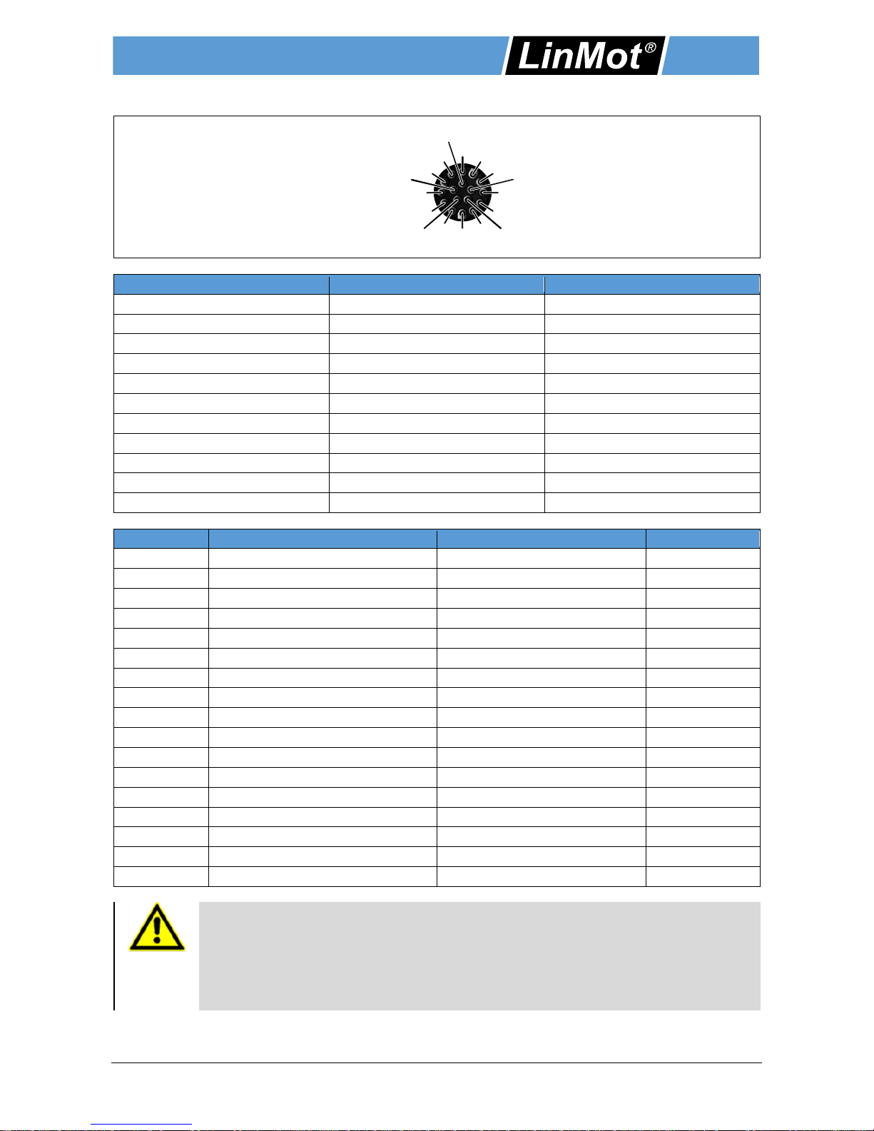
7.1.2 Sensor Connector
Shielded twisted pair
Encoder Kabel d = 0.5 mm2 / 0.25 mm2
Pin
P10-70
Wire Color
1
+5VDC
Red
2
GND
Black
3
Sense +5V
White
4
Sense GND
Brown
5
Motor Link C +
Pink
6
Motor Link C -
Grey
7
Sin +
Yellow
8
Sin -
Orange
9
Cos +
Green
10
Cos -
Blue
11 bis 17
n. c.
- Pin
P10-70-D01
P10-70-D02
Wire Color
1
3…13 VDC
3…13 VDC
White
2
GND
GND
Brown
3
Sense Vcc (optional)
Sense Vcc (optional)
Green
4
Sense GND (optional)
Sense GND (optional)
Yellow
5
Do not connect
Do not connect
- 6 Do not connect
Do not connect
-
7
Sine +
Sine +
Grey
8
Sine -
Sine -
Pink
9
Cosine +
Cosine +
Blue
10
Cosine -
Cosine -
Red
11
Ref +
Ref +
Black
12
Ref -
Ref -
Purple
13
Hall U
Hall U
Grey-Red
14
Hall V
Hall V
Red-Blue
15
Hall W
Hall W
White-Green
16
Temp + (KTY84/130 Char.)*
Temp + (PTC 400/20k Char.)*
Yellow-Brown
17
Temp - (KTY84/130 Char.)*
Temp - (PTC 400/20k Char.)*
White-Yellow
* Temperatur circuit
The temperature evaluation circiut must be powered from the encoder supply and must be
at the same potential. The grounds of the temperature evaluation circuit and the encoder
have to be connected. The encoder must have been powered on for at least 50 ms, before
valid temperatures can be measured. If the encoder is powered off, 200k Ohms are
measured between Pins 16 and 17. The maximum voltage between Pin 16 and 17 must not
exceed 16 VDC. The maximum current must not exceed 15 mA.
10
4
14
15
17
13
16
1
7
9
11
5
3
2
12
6
8

Installation Guide Linear Motors ENG
Page 34 / 41 P10-70 / P10-70-D01/02/03 NTI AG / LinMot
Pin
P10-70-D03
Wire Color
1
3…13 VDC
Red
2
GND
Black
3
Sense Vcc (optional)
White
4
Sense GND (optional)
Brown
5
Do not connect
-
6
Do not connect
- 7 Sine +
Yellow
8
Sine -
Orange
9
Cosine +
Green
10
Cosine -
Blue
11
n. c.
n. c.
12
n. c.
n. c.
13
n. c.
n. c.
14
Do not connect
n. c.
15
n. c.
n. c.
16
n. c.
n. c.
17
n. c.
n. c.
7.2 Stator checking
The following tables show the resistive value between the different connector pins for each stator type. If the
value is not within a range of +/- 10% the stator may be damaged (temperature of the stator for all
measurements: 20°C).
PS10-70x80U-BL-QJ (0150-1291) PS10-70x80U-BL-QJ-D01 (0150-2282)
PS10-70x80U-BL-QJ-D02 (0150-2360) PS10-70x80U-BL-QJ-D03 (0150-2708)
Phase U / Phase V
Pin 1 / Pin 4
12.8 @ 20 °C
Phase V / Phase W
Pin 4 / Pin 3
12.8 @ 20 °C
Phase W / Phase U
Pin 3 / Pin 1
12.8 @ 20 °C
Casing
Any phases / Casing
> 200 M@ 20 °C
KTY + / KTY -
(only Series D03)
Pin A / Pin B
581 ± 26 @ 20 °C
603 ± 26 @ 25 °C
PS10-70x160U-BL-QJ (0150-1292) PS10-70x160U-BL-QJ-D01 (0150-2283)
PS10-70x160U-BL-QJ-D02 (0150-2361) PS10-70x160U-BL-QJ-D03 (0150-2709)
Phase U / Phase V
Pin 1 / Pin 4
8.1 @ 20 °C
Phase V / Phase W
Pin 4 / Pin 3
8.1 @ 20 °C
Phase W / Phase U
Pin 3 / Pin 1
8.1 @ 20 °C
Casing
Any phases / Casing
> 200 M@ 20 °C
KTY + / KTY -
(only Series D03)
Pin A / Pin B
581 ± 26 @ 20 °C
603 ± 26 @ 25 °C
PS10-70x240U-BL-QJ (0150-1293) PS10-70x240U-BL-QJ-D01 (0150-2284)
PS10-70x240U-BL-QJ-D02 (0150-2362) PS10-70x240U-BL-QJ-D03 (0150-2710)
Phase U / Phase V
Pin 1 / Pin 4
6.2 @ 20 °C
Phase V / Phase W
Pin 4 / Pin 3
6.2 @ 20 °C
Phase W / Phase U
Pin 3 / Pin 1
6.2 @ 20 °C
Casing
Any phases / Casing
> 200 M@ 20 °C
KTY + / KTY -
(only Series D03)
Pin A / Pin B
581 ± 26 @ 20 °C
603 ± 26 @ 25 °C

Installation Guide Linear Motors ENG
NTI AG / LinMot P10-70 / P10-70-D01/02/03 Page 35 / 41
PS10-70x320U-BL-QJ (0150-1284) PS10-70x320U-BL-QJ-D01 (0150-2285)
PS10-70x320U-BL-QJ-D02 (0150-2343) PS10-70x320U-BL-QJ-D03 (0150-2711)
Phase U / Phase V
Pin 1 / Pin 4
5.4 @ 20 °C
Phase V / Phase W
Pin 4 / Pin 3
5.4 @ 20 °C
Phase W / Phase U
Pin 3 / Pin 1
5.4 @ 20 °C
Casing
Any phases / Casing
> 200 M@ 20 °C
KTY + / KTY -
(only Series D03)
Pin A / Pin B
581 ± 26 @ 20 °C
603 ± 26 @ 25 °C
PS10-70x400U-BL-QJ (0150-1294) PS10-70x400U-BL-QJ-D01 (0150-2286)
PS10-70x400U-BL-QJ-D02 (0150-2363) PS10-70x400U-BL-QJ-D03 (0150-2712)
Phase U / Phase V
Pin 1 / Pin 4
6.8 @ 20 °C
Phase V / Phase W
Pin 4 / Pin 3
6.8 @ 20 °C
Phase W / Phase U
Pin 3 / Pin 1
6.8 @ 20 °C
Casing
Any phases / Casing
> 200 M@ 20 °C
KTY + / KTY -
(only Series D03)
Pin A / Pin B
581 ± 26 @ 20 °C
603 ± 26 @ 25 °C
7.3 Maintenance of linear motors
The stators will be shipped with an initial lubrication. Maintenance will only be required if the motors run 'dry'
or there is a heavy pollution of the motors.Under normal industrial conditions (5 day, 8 h / day) one inspection
every 3 months is adequate. The inspection cycle must be shortened if severe motor loads or deviating
conditions exist. These conditions are for example:
Permanent fouling
Direct sunshine
Low Humidity
Outdoor operation
Increased operating temperature
7.3.1 Mounting
Sliders with a length ≤ 500 mm (20 in) are to be inserted in a clean contition in the stator.
Sliders with a length > 500 mm (20 in) must be lubricated with LU02. 4 g of lubricant per meter slider is
enough to create a film of lubricant on the surface of the sliders. 4 g (0.14 oz) is about ½ of a hazel-nut.
The grease can be applied by hand or with a soft paper towel.
If wipers are used then the inner side of the seals of the wipers must be lubricated as well.
Basically, it must be ensured that only a thin film of grease is applied. 4 g of grease per
1000 mm of slider length is sufficient for this purpose. Over lubrication leads to a gumming
of the grease, which appears particularly at higher operating temperatures! In this case, a
complete cleaning of the motor has to be made.
7.3.2 Inspection
Inspections have to be executed according to the operating condition and the load of motors. Following
points have to be checked during inspection:
a) Is a film of lubricant on the slider? If not -> Lubrication
b) Is the wiper (if existent) without visible wear? If not -> Replace wipers
c) Is the lubricant homogeneous and not decomposed? In case of negation -> Cleaning (stator, slider) +
Lubrication
d) Can the slider be moved easily? If not -> Cleaning (stator, slider) + Lubrication
Installation Guide Linear Motors ENG
Page 36 / 41 P10-70 / P10-70-D01/02/03 NTI AG / LinMot
7.3.3 Cleaning
Pull the sliders carefully out of the stator.
Attention! Strong magnetic attraction forces (note safety instructions on page 5)!
Use non magnetic material (e.g. wood) to cover close-by iron constructions.
Clean slider and stator with a soft disposable paper, ideally with the help of LU06 cleaning spray (or
methylated spirits or alcohol).
Afterwards, lubricate the bore of the stators with about 2-3 g (0.1 oz) grease LU02.
There should only be a slight film of lubricant.
Note: Do not over lubricate!
Finally, slider should be lubricated according to the chapter 'mounting'.
7.3.4 Cleaning agent / Lubricant
For the cleaning of LinMot stators and sliders cleaning agent spray LU06 is recommended.
To improve the sliding characteristics between the stainless steel surface of the slider and the plastic slide
bearing the LinMot lubricant LU02 is prescribed.
Ordering information
Item
Description
Item-No.
LU06-250
Klüberfood NH1 4-002 Spray* (250 ml)
0150-2394
LU02-08
Lubricant for linear motors ** (8 g)
0150-1953
LU02-50
Lubricant for linear motors ** (50 g)
0150-1954
LU02-1000
Lubricant for linear motors ** (1000 g)
0150-1955
* LinMot Spray LU06 corresponds to KLÜBERFOOD NH1 4-002 which was developed for the food
processing industry.
** LinMot LU02 Lubricant corresponds to KLÜBERSYNTH UH1 14-31 which was developed for the food
processing industry.
Installation Guide Linear Motors ENG
NTI AG / LinMot P10-70 / P10-70-D01/02/03 Page 37 / 41
8 Storage, transport, installation altitude
Sliders are to be stored and transported only in the plastic containers (with cardboard inlay) provided for
this purpose, or already installed and secured in LinMot P stators.
Remove the slider from this plastic containers only for assembling.
The storage area must be dry, dust-free, frost-free and vibration-free.
The relative air humidity should be less than 60 %.
Prescribed storage temperature: -15 °C…70 °C
The motor must be protected against extreme weather conditions.
The air in the storage area must not contain any harmful gases.
The max. installation altitude is 2'000 m (for higher values contact LinMot) above sea level.
From 1'000 m, derating of 1 °C per 100 m is to be considered for air cooling.
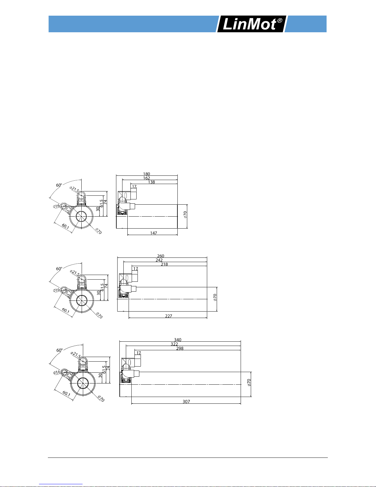
9 Dimensions
9.1 Stator
9.1.1 PS10-70x80
9.1.2 PS10-70x160
9.1.3 PS10-70x240

Installation Guide Linear Motors ENG
Page 38 / 41 P10-70 / P10-70-D01/02/03 NTI AG / LinMot
9.1.4 PS10-70x320
9.1.5 PS10-70x400
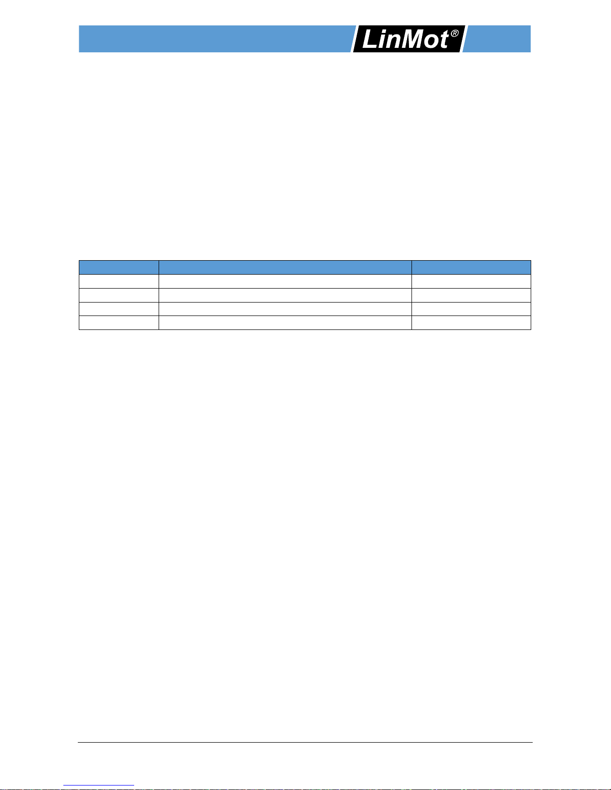
9.2 Slider
Slider front end M 10 thread
Item
Item-No.
Length L [mm / in]
PL10-28x290/240
0150-2193
290 / 11.42
PL10-28x390/340
0150-2194
390 / 15.36
PL10-28x490/440
0150-2195
490 / 19.3
PL10-28x590/540
0150-2196
590 / 23.42
PL10-28x690/640
0150-2197
690 / 27.18
PL10-28x790/740
0150-2198
790 / 31.11
PL10-28x890/840
0150-2199
890 / 35.05
PL10-28x990/940
0150-2203
990 / 39
PL10-28x1190/1140
0150-2204
1190 / 46.87
PL10-28x1390/1340
0150-2205
1390 / 54.75
PL10-28x1590/1540
0150-2206
1590 / 62.62
PL10-28x1790/1740
0150-2207
1790 / 70.5
PL10-28x1990/1940
0150-2208
1990 / 78.38

Installation Guide Linear Motors ENG
NTI AG / LinMot P10-70 / P10-70-D01/02/03 Page 39 / 41
10 UL Certificate

Installation Guide Linear Motors ENG
Page 40 / 41 P10-70 / P10-70-D01/02/03 NTI AG / LinMot
11 Declaration of Conformity and CE-marking
Wir
We
Nous NTI AG
Bodenaeckerstrasse 2
8957 Spreitenbach
erklären in alleiniger Verantwortung, dass das Produkt
declare under our sole responsibility that the product
declarons sous notre seule responsabilité que le produit
Product
Item-No.
Product
Item-No.
PS10-70x80U-BL-QJ
0150-1291
PS10-70x320U-BL-QJ-D11
0150-2716
PS10-70x160U-BL-QJ
0150-1292
PS10-70x400U-BL-QJ-D11
0150-2717
PS10-70x240U-BL-QJ
0150-1293
PS10-70x80U-BL-QJ-D02
0150-2360
PS10-70x320U-BL-QJ
0150-1284
PS10-70x160U-BL-QJ-D02
0150-2361
PS10-70x400U-BL-QJ
0150-1294
PS10-70x240U-BL-QJ-D02
0150-2362
PS10-70x80U-BL-QJ-D01
0150-2282
PS10-70x320U-BL-QJ-D02
0150-2343
PS10-70x160U-BL-QJ-D01
0150-2283
PS10-70x400U-BL-QJ-D02
0150-2363
PS10-70x240U-BL-QJ-D01
0150-2284
PS10-70x80U-BL-QJ-D03
0150-2708
PS10-70x320U-BL-QJ-D01
0150-2285
PS10-70x160U-BL-QJ-D03
0150-2709
PS10-70x400U-BL-QJ-D01
0150-2286
PS10-70x80U-BL-QJ-D03
0150-2710
PS10-70x80U-BL-QJ-D11
0150-2713
PS10-70x320U-BL-QJ-D03
0150-2711
PS10-70x160U-BL-QJ-D11
0150-2714
PS10-70x400U-BL-QJ-D03
0150-2712
PS10-70x240U-BL-QJ-D11
0150-2715
konform ist mit den Anforderungen der Richtlinien,
is conform to the provisions of directives,
est conformé aux exigences des directives,
2014/35/EU (LVD) + 2014/30/EU (EMCD)
gestützt auf die folgenden Normen,
based on the following standards,
base aux normes suivants,
LVD EN61800-5-1:2007
EMCD EN61000-6-2:2005
EN61000-6-4:2007
Jahr der CE-Kennzeichnung:
Year of CE marking:
Annee du marquage CE: 2013
Spreitenbach, 10.03.2017
Dr.-Ing. Ronald Rohner Dr.-Ing. Marco Hitz
CEO NTI AG RESPONSIBLE FOR DOCUMENTATION

© 2018 NTI AG / LinMot Subject to alterations
ALL LINEAR MOTION
FROM A SINGLE SOURCE
Visit http://www.linmot.com/ to find a distributor next to you.
LinMot Europe
NTI AG - LinMot & MagSpring
Bodenaeckerstrasse 2
CH-8957 Spreitenbach
Sales / Administration: +41-(0)56-419 91 91
office@linmot.com
Tech. Support: +41-(0)56-544 71 00
support@linmot.com
Tech. Support (Skype): skype:support.linmot
Fax: +41-(0)56-419 91 92
Web: http://www.linmot.com/
LinMot USA
LinMot USA, Inc.
N1922 State Road 120, Unit 1
Lake Geneva, WI 53147
Sales / Administration : 262-743-2555
Tech. Support: usasupport@linmot.com
E-Mail: usasales@linmot.com
Web: http://www.linmot-usa.com/
 Loading...