

Page 1
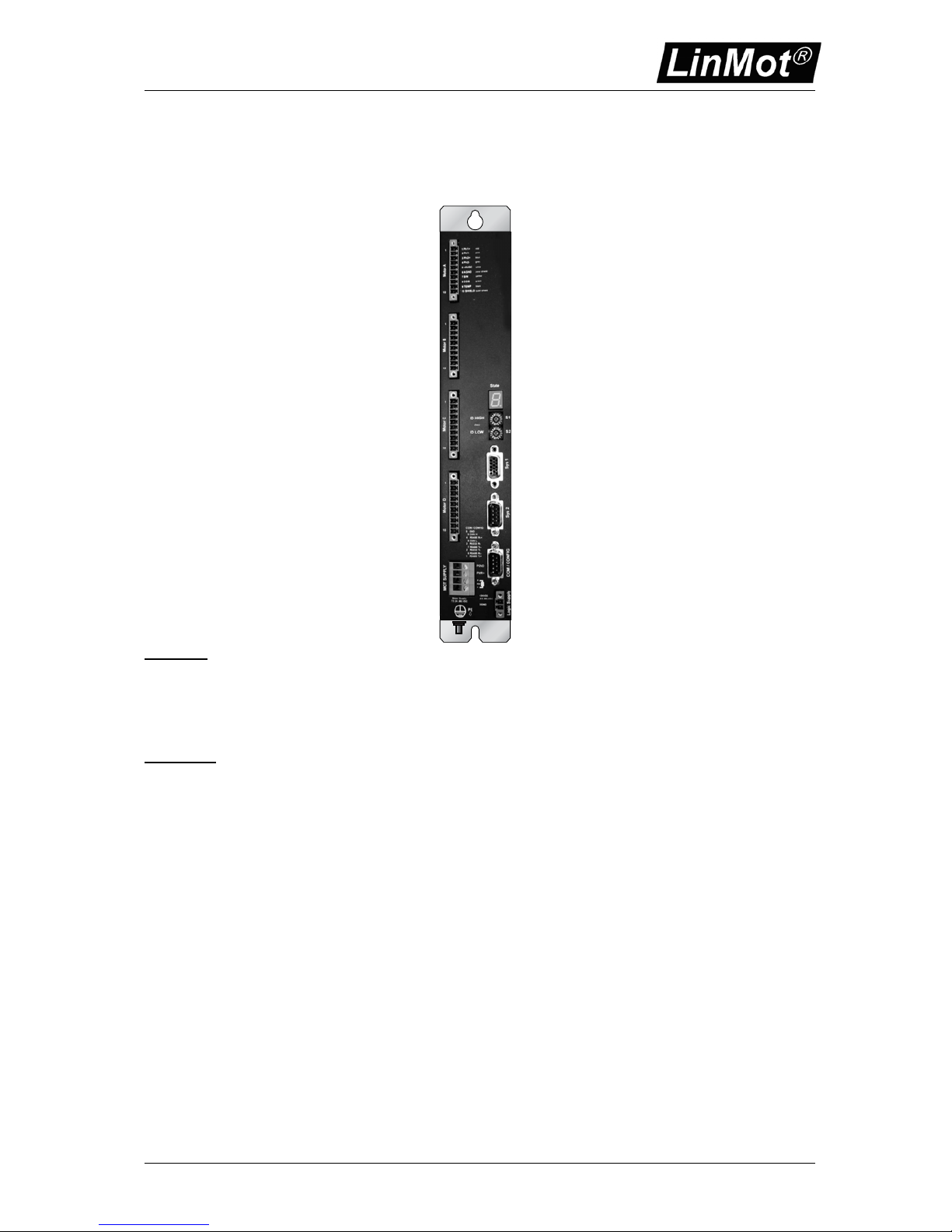
Controller Series E1031/2031/4031 V3
NTI AG Installation: E1031/E2031/E4031 V3 series / 28.07.2010 Page 1/17
Installation Guide
Controller Series E1031/E2031/E4031 V3
1 Ph1+
2 Ph1-
3 Ph2+
4 Ph2-
5 +5VDC
6 AGND
7 SIN
8 COS
9 TEMP
10 SHIELD
Motor Supply
72 (24..80) VDC
Logic Supply
24 (22..50) VDC
5 GND
9 CAN H
8 CAN L
7
6
4
3 RS232 Rx
2 RS232 Tx
1
1
10
RR
PWR+
PGND
+24VDC
DGND
nc
MOT SUPPLY
COM / CONFIG
Sys 2 Sys 1
Motor D
-
+
State
PE
1
10
Motor C
1
10
Motor B
1
10
Motor A
red
pink
blue
grey
white
inner shield
yellow
green
black
outer shield
E4001-MT
PN 0150-2307
LinMot
Products
E1031-DP(-ME)
E2031-DP(-ME)
E4031-DP(-ME)
Content
IMPORTANT NOTES FOR E1031/E2031/E4031 SERIES CONTROLLERS ..............2
SYSTEM OVERVIEW ............................................................................................................. 3
E1031 SERIES FUNCTION AND WIRING.........................................................................4
POWER SUPPLY AND GROUNDING................................................................................5
DESCRIPTION OF THE CONNECTORS / INTERFACES ..............................................6
MECHANICAL DIMENSION............................................................................................... 10
POWER SUPPLY REQUIREMENT...................................................................................11
REGENERATION OF POWER / REGENERATION RESISTOR..................................11
ORDERING INFORMATION...............................................................................................12
DECLARATION OF CONFORMITY CE-MARKING.......................................................13
ERROR CODES.................................................................................................................... 14
STATE MACHINE.................................................................................................................16
CONTACT ADDRESSES ....................................................................................................17
Page 2
Controller Series E1031/2031/4031 V3
NTI AG Installation: E1031/E2031/E4031 V3 series / 28.07.2010 Page 2/17
Important notes for E1031/E2031/E4031 series controllers
CAUTION !!
In order to assure a safe and error free operation, and to avoid
severe damage to system components, all system components
must be directly attached to a single ground bus that is earth or
utility grounded.
Each system component should be tied directly to the ground bus
(star pattern), rather than daisy chaining from component to
component. (LinMot motors are properly grounded through their
power cables when connected to LinMot controllers.)
All connectors must not be connected or disconnected while DC
voltage is present. Do not disconnect system components until all
LinMot controllers LED’s have turned off. (Capacitors in the power
supply may not fully discharge for several minutes after input
voltage has been disconnected). Failure to observe these
precautions may result in severe damage to electronic components
in LinMot motors and/or controllers.
Do not switch Power Supply DC Voltage. All power supply switching
and E-Stop breaks should be done to the AC supply voltage of the
power supply.
Do not connect or disconnect the motors from controllers
with
voltage present. Wait to connect or disconnect motors until all
LinMot controllers LED’s have turned off. (Capacitors may not fully
discharge for several minutes after power has been turned off).
Failure to observe these precautions may result in severe damage
to electronic components in LinMot motors and/or controllers.
© 2010 NTI Ltd
This work is protected by copyright.
Under the copyright laws, this publication may not be reproduced or transmitted in any form, electronic or mechanical, including
photocopying, recording, microfilm, storing in an information retrieval system, not even for didactical use, or translating, in whole
or in part, without the prior written consent of NTI AG.
LinMot® is a registered trademark of NTI AG.
Note
The information in this documentation reflects the stage of development at the time of press and is therefore without obligation.
NTI AG reserves itself the right to make changes at any time and without notice to reflect further technical advance or product
improvement.
Page 3
Controller Series E1031/2031/4031 V3
NTI AG Installation: E1031/E2031/E4031 V3 series / 28.07.2010 Page 3/17
System Overview
1 Ph1+
2 Ph13 Ph2+
4 Ph25 +5VDC
6 AGND
7 SIN
8 COS
9 TEMP
10 SHIELD
Motor Supply
72 (24..80) VDC
Logic Supply
24 (22..50) VDC
5 GND
9 CAN H
8 CAN L
7
6
4
3 RS232 Rx
2 RS232 Tx
1
1
10
RR
PWR+
PGND
+24VDC
DGND
nc
MOT SUPPLY
COM / CONFIG
Sys 2 / DP
Sys 1
Motor D
-
+
State
PE
1
10
Motor C
1
10
Motor B
1
10
Motor A
red
pink
blue
grey
white
inner shield
yellow
green
black
outer shield
E4031-DP
PN 0150-2319
LinMot
RS232
Interface
to PC for
Configuration
Linear Motor with internal Position Feedback
Power Supply
Signal
nom. 24VDC
Interfaces
to PLC or
PC
Interfaces
to PLC or
PC
From AC Mains
Power Supply Signal
Power Supply Motor
Power Supply
Motor
nom. 72VDC
From AC Mains
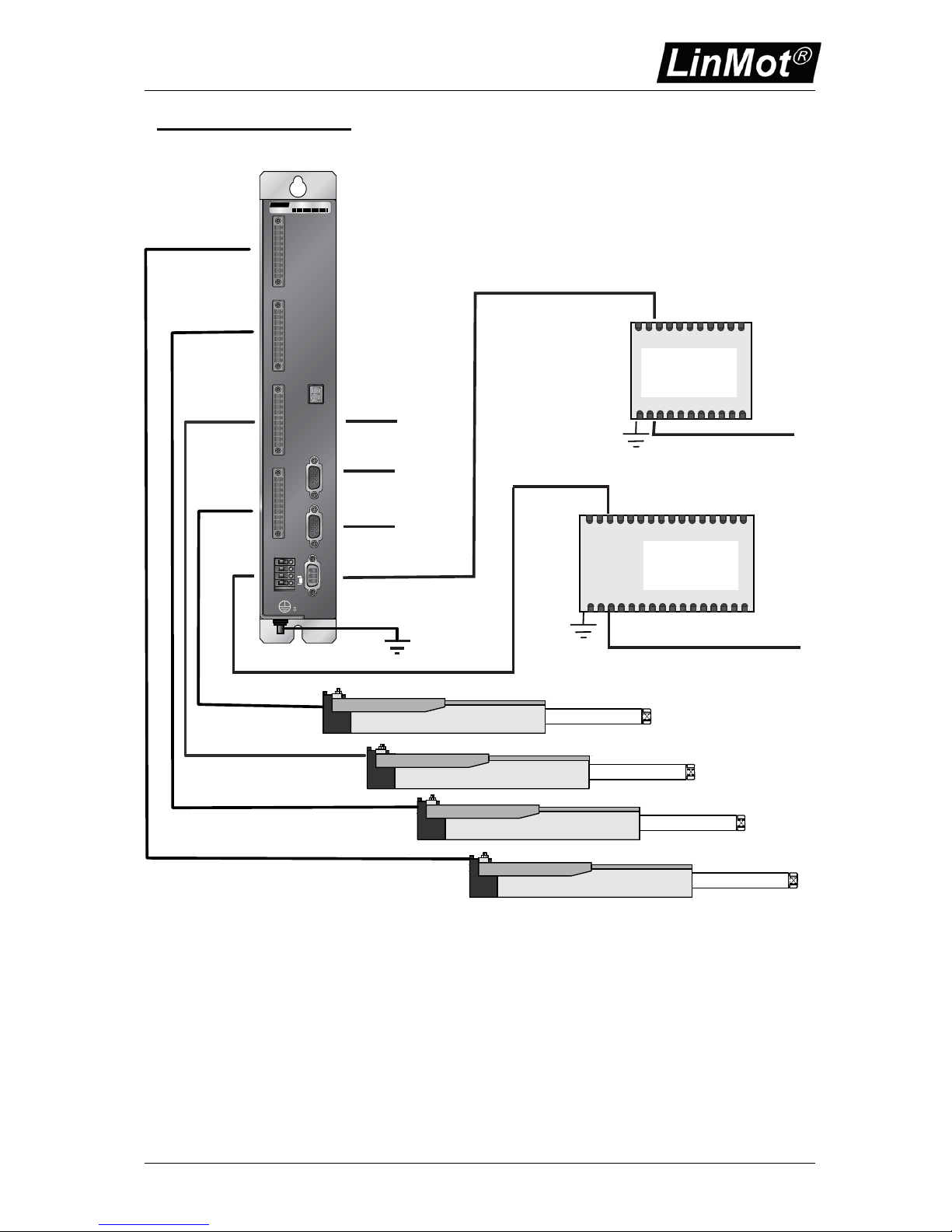
Complete E4031 Controller based system (E1031 and E2031 controllers will only drive one
respectively two motors). Power Supply for Signal and Motor may be the same device (see later).
Page 4

Controller Series E1031/2031/4031 V3
NTI AG Installation: E1031/E2031/E4031 V3 series / 28.07.2010 Page 4/17
E1031 series Function and Wiring
2-Phase Powerstage (s)
72VDC (24..85VDC)
8A Phase Current
1
2
3
4
5
6
7
8
9
RS232
TTL
0-5V
A/D
Mot A ( addtional Motors B,C,D)
Com. RS232
Linear Motor
Motor Internal
Hall Sensors
Motor Phases*
Hall Sensors* /Temp Sensor
*use special double shielded Linear
Motor cable (see catalogue)
for RS232 PC connection use 1:1cable
Pin 2 - Pin 2, Pin 3 - Pin 3, Pin 5 - Pin 5
min. 0.5mm2 / AGW20 for 3A
AC-Mains
- Circuit Breaker
- Fuse
Emergency
Stop Breaker
=
+
48...72VDC
Power Supply motor
PWR motor
GND
8 AT (E1031)
16 AT (else)
signal components
5
4
3
2
1
9
8
7
6
DP
E1031
Controller
use only
shielded cables
10
1
ID High
ID Low
GND (isolated)
CNTR-P
RxD/TxD-P
6
1
2
7
4
8
3
9
5
RxD/TxD-N
+ 5 V (isolated)
Profibus ID Addresses
use only special Profibus
cables and connectors
RR-
PE
RR+
PWR+
PGND
AC-Mains
- Circuit Breaker
- Fuse
=
+
24VDC
Power Supply signal
PWR signal
GND
3 AT
Picture shows typical wiring of a single axes controller. Multiple axes controller will have additional motor
connectors.
Page 5
Controller Series E1031/2031/4031 V3
NTI AG Installation: E1031/E2031/E4031 V3 series / 28.07.2010 Page 5/17
Power Supply and Grounding
=
Galvanically Isolated Power Supply:
- Switch Mode Power Supply (for example S01-24/150)
+
24VDC
AC-Mains
- Circuit Breaker
- Fuse
AC-Mains
- Circuit Breaker
- Fuse
Emergency
Stop Breaker
-
=
Galvanically Isolated Power Supply:
- Switch Mode Power Supply (for example S01-72/600)
- Transformer with Rectifier Bridge (for example T01-72/900)
+
72VDC
-
PE
PWR signal
Power Supply signal
Power Supply motor
PWR motor
GND
GND
Ground Bus
1 Ph1+
2 Ph1-
3 Ph2+
4 Ph2-
5 +5VDC
6 AGND
7 SIN
8 COS
9 TEMP
10 SHIELD
Motor Supply
72 (24..80) VDC
Logic Supply
24 (22..50) VDC
5 GND
9 CAN H
8 CAN L
7
6
4
3 RS232 Rx
2 RS232 Tx
1
1
10
RR
PWR+
PGND
+24VDC
DGND
nc
MOT SUPPLY
COM / CONFIG
Sys 2 Sys 1
Motor D
-
+
State
PE
1
10
Motor C
1
10
Motor B
1
10
Motor A
red
pink
blue
grey
white
inner shield
yellow
green
black
outer shield
E4001-MT
PN 0150-2307
LinMot
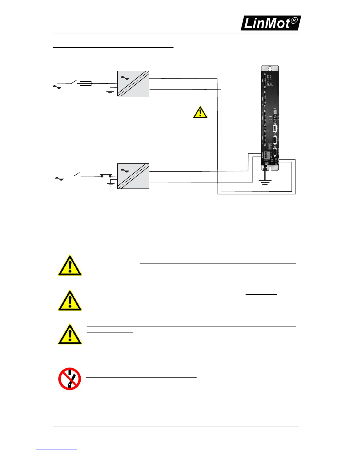
In order to assure a safe and error free operation, and to avoid severe damage to
system components, all system components must be well grounded to either a
single earth or utility ground. This includes both LinMot and all other control system
components to the same ground bus.
Each system component should be tied directly to the ground bus (star pattern
), rather
than daisy chaining from component to component. (LinMot motors are properly
grounded through their power cables when connected to LinMot controllers.)
Power supply connectors must not be connected or disconnected while DC
voltage is present. Do not disconnect system components until all LinMot controllers
LED’s have turned off. (Capacitors in the power supply may not fully discharge for
several minutes after input voltage has been disconnected). Failure to observe these
precautions may result in severe damage to electronic components in LinMot motors
and/or controllers.
Do not switch Power Supply DC Voltage.
All power supply switching and E-Stop
breaks should be done to the AC supply voltage of the power supply. Failure to observe
these precautions may result in severe damage to controller.
Page 6
Controller Series E1031/2031/4031 V3
NTI AG Installation: E1031/E2031/E4031 V3 series / 28.07.2010 Page 6/17
Description of the connectors / Interfaces
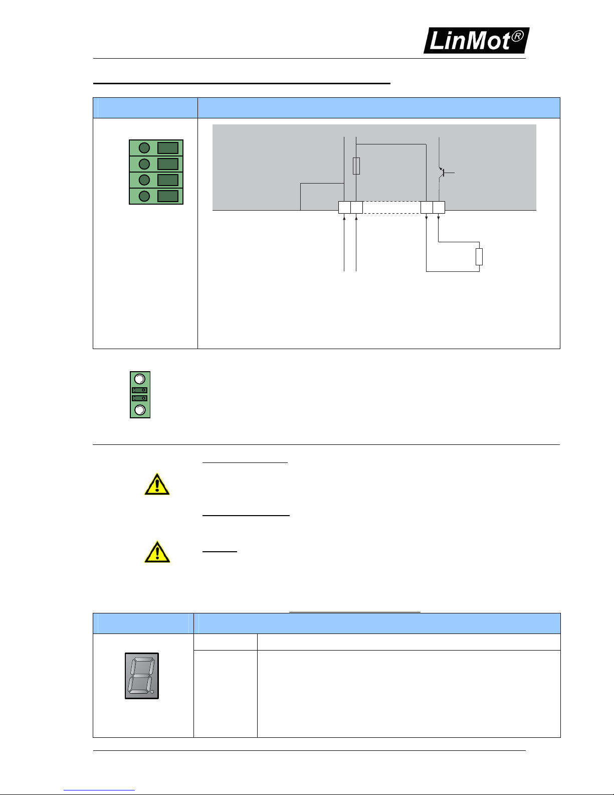
Power Supply
Motor Supply
RR-
RR+
PWR+
PGND
GND
72VDC (24..85VDC)
72VDC (24...85VDC)
GND
Motor Supply
4
GND internally
connected to
controller housing
Internal
Fuse
8AT E1001
16AT E2001/E4001
1
PGND
PWR+
Optional:
Regeneration
Resistor (external)
RR01-10/60 (10R, 60W)
RR+
RR-
GND
2 3
- Tightening torque: min 0.4Nm
- Screw thread: M 2,5
- Conductor cross section max. 2.5mm
2
- Internal Fuse: E4031/E2031: 16AT (Schurter SMD-SPT, 0001.2716.xx, UL File Number: E41599)
E1001: 8AT (Schurter SMD-SPT, 0001.2713.xx, UL File Number: E41599)
Logic Supply
+24VDC
DGND
Pin:
2 Power Supply Signal 24VDC (22..53VDC)
1 Logic GROUND
Plug component (Phoenix Contact, MC 1,5/ 2-STF-3,81):
- Tightening torque: min 0.22Nm
- Screw thread: M 2
- Conductor cross section max. 1.5mm
2
- Internal Fuse: 3AT (Schurter OMT125, 3404.0118.xx, UL File Number: E41599)
Power Supply Motor:
Wiring: 2.5 mm² (AWG12), max length 5 m
Nominal Supply Voltage 72VDC (24...85VDC). Absolute max. Rating is 92 VDC
Motor Supply PGND should NOT be externally connected to earth!
Power Supply Signal:
Wiring: 1.5 mm² (AWG16), max length 5 m
Supply Voltage 24...48VDC. Absolute max. Rating 48VDC + 10%
Caution:
By exceeding 53VDC Power Supply Signal, the controller will go into error state, voltage higher than 55
VDC will damage the controller!
By exceeding 92 VDC Motor Supply Signal, the controller will go into error state, voltage higher than
100VDC will damage the controller!
Do not switch Power Supply DC Voltage. All power supply switching and E-Stop breaks should be done
to the AC supply voltage of the power supplies
Power supply connectors must not be connected or disconnected
while DC voltage is present.
7-Segment Display State Display
State: Description:
Red 7-Segment Display
0
1
2
7
8
9
Exxxx
Firmware stopped
WAIT FOR DISABLE State
DISABLE State (Init not Done)
DISABLE State (Init Done)
STOP State
RUN State
INIT State
Error State (See Chapter Error Codes on page 14 for further description)
If a warning is active, the display is blinking!
Page 7
Controller Series E1031/2031/4031 V3
NTI AG Installation: E1031/E2031/E4031 V3 series / 28.07.2010 Page 7/17
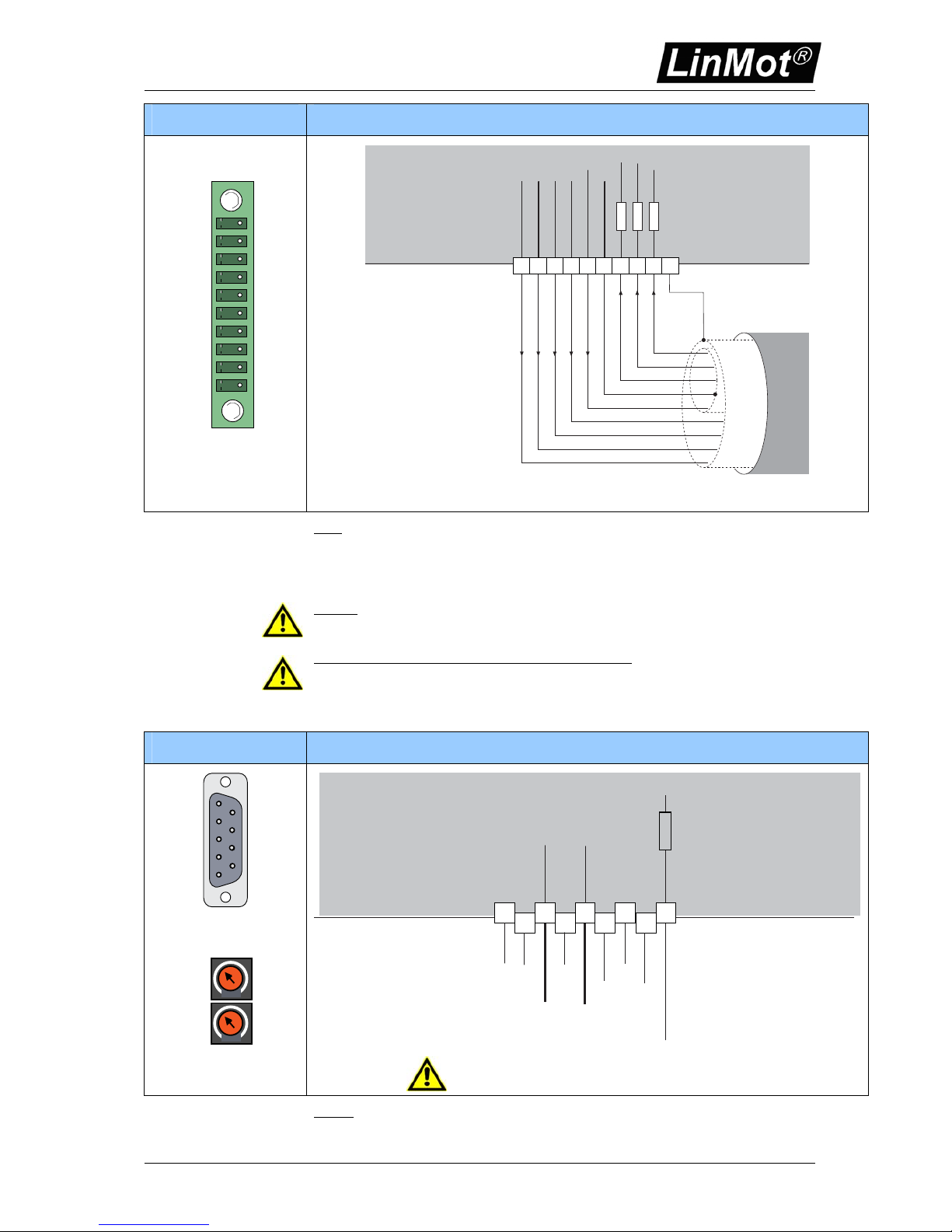
Mot A (B,C,D) Motor Connector
10
1
Cosine
Sine
AGND
+5VDC
Phase 2-
Phase 2+
Phase 1-
Phase 1+
2k2
2k2
10k
Te mp .
+5VDC
black
green
yellow
inner shield
grey
blue
pink
white
red
Outer shield connected
GND GND
+5VDC
Mot A (B,C,D)
GND
Extension Cable
2134 7658910
Note:
- Use only special double-shielded Linear Motor Cable (see datasheet ‘extension cables’)
- Use +5V (Pin 3) and AGND (Pin 6) only for motor internal Hall Sensor supply (max. 100mA).
- Do NOT connect AGND (Pin 6) to ground or earth!
- Inner shield (AGND) and outer shield (earth) must be isolated to each other.
Caution:
- Wrong Motor wiring may damage Linear Motors and/or Servo Controller.
- If you are assembling motor cables by your own, double check motor wiring carefully before power up.
Do not connect or disconnect the motors from controllers
with voltage present. Wait to connect or
disconnect motors until all LinMot controller LED’s have turned off. (Capacitors may not fully discharge for
several minutes after power has been turned off).Failure to observe these precautions may result in
severe damage to electronic components in LinMot motors and/or controllers. Depending on the
environment the outer shield of the motor cable should be directly connected to the control cabinet where
the controller is built in to get the best EMC results.
Com COM (RS-232)
5
4
3
2
1
9
8
7
6
DSUB-9 (male)
S2
S1
ID High
ID Low
ID for DP and CAN
GND
GND
6
1
2
7
4
8
3
9
5
RS-232 TX
100R
RS-232 RX
CAN L
CAN H
RS-485 Y (TX+)
RS-485 A (RX+)
RS-485 B (RX-)
RS-485 Z (Tx-)
Use 1:1 Cable to connect to PC!
RS232: 9.6kBaud, use 1:1 connection cable to PC
CAN needs external termination (see manual)
Page 8
Controller Series E1031/2031/4031 V3
NTI AG Installation: E1031/E2031/E4031 V3 series / 28.07.2010 Page 8/17
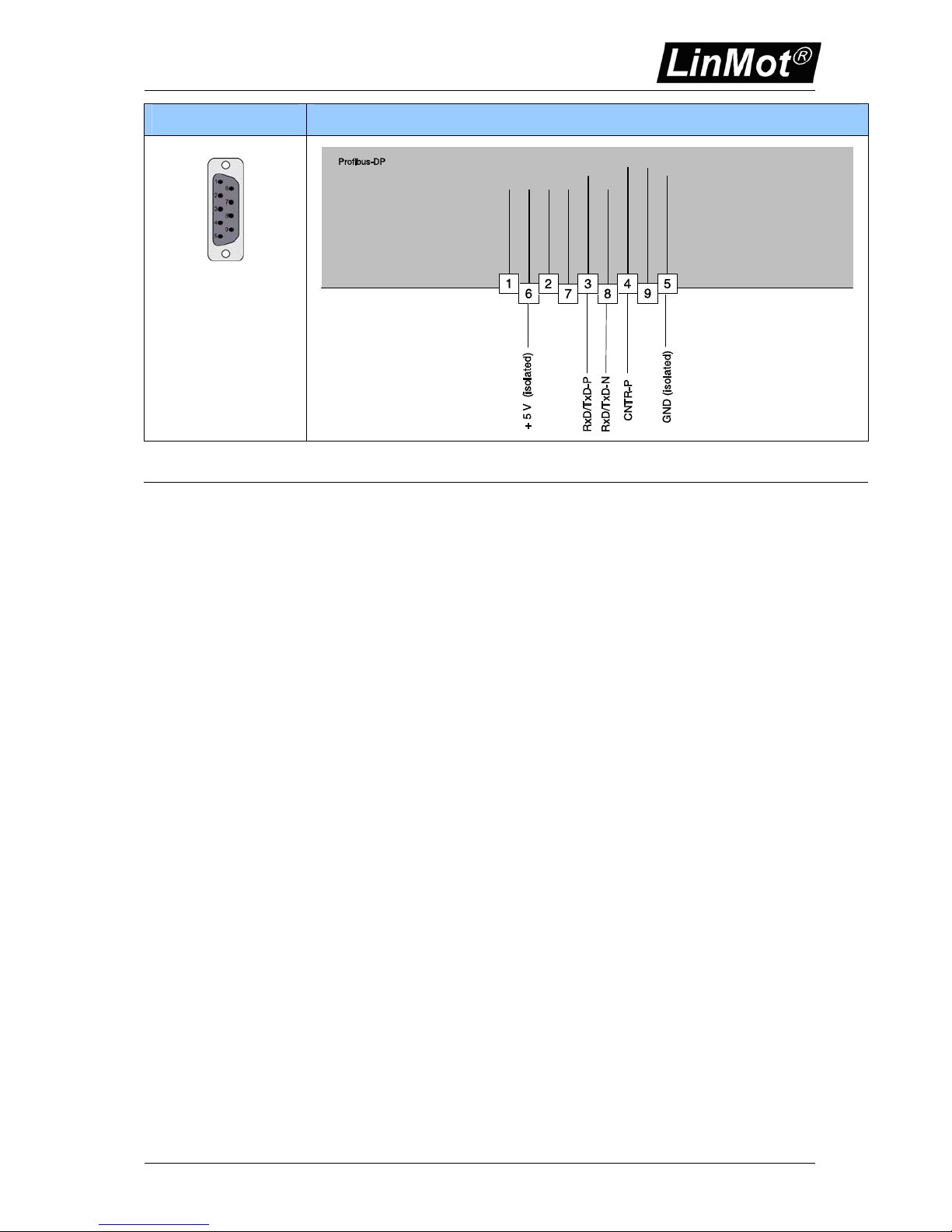
DP Profibus Connector
DSUB-9 (female)
Isolated 5V output: max 50 mA
Page 9
Controller Series E1031/2031/4031 V3
NTI AG Installation: E1031/E2031/E4031 V3 series / 28.07.2010 Page 9/17
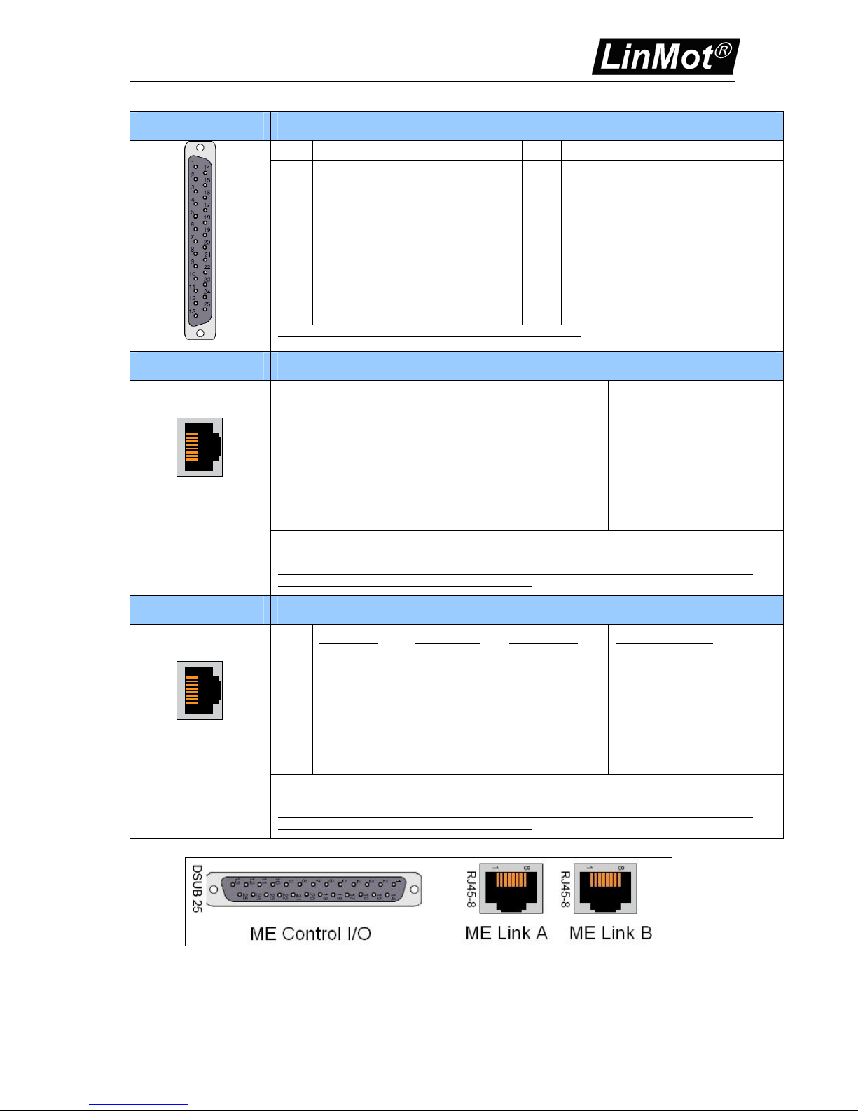
ME Control I/O Master Encoder Control I/O
Pin Pin
1
2
3
4
5
6
7
8
9
10
11
12
13
+5V ENC OUT
DIG IN 2
DIG IN 4
DIG IN 6
DIG IN 8
DIG OUT 1
DIG OUT 3
DIG OUT 5
DIG OUT 7
GND DIG OUT
14
15
16
17
18
19
20
21
22
23
24
25
VCC ENC IN
GND ENC
DIG IN 1
DIG IN 3
DIG IN 5
DIG IN 7
GND DIG IN
VCC DIG OUT
DIG OUT 2
DIG OUT 4
DIG OUT 6
DIG OUT 8
DSUB 25 female
Further details can be found on the Master Encoder User manual
ME Link A Master Encoder Link A
1
2
3
4
5
6
7
8
case
Incremental:
Step/Direction:
A+ Step+
A- StepB+ Direction+
Z+ ZeroZ- Zero+
B- DirectionVCC ENC VCC ENC
GND ENC GND ENC
Shield Shield
EIA/TIA 568A colors:
Green/White
Green
Orange/White
Blue
Blue/White
Orange
Brown/White
Brown
1
8
RJ45-8
Further details can be found on the Master Encoder User manual
Adapter Cable from RJ45 to DSUB-9 (which was used on the Master Encoder Extension Board on the
E4000 series controller has article number 0150-1866)
ME Link B Master Encoder Link B
1
2
3
4
5
6
7
8
case
Incremental:
Step/Direction: Loop Through:
A+ Step+ Link A pin 1
A- Step- Link A pin 2
B+ Direction+ Link A pin 3
Z+ Zero- Link A pin 4
Z- Zero+ Link A pin 5
B- Direction- Link A pin 6
VCC ENC VCC ENC VCC ENC
GND ENC GND ENC VCC ENC
Shield Shield Shield
EIA/TIA 568A colors:
Green/White
Green
Orange/White
Blue
Blue/White
Orange
Brown/White
Brown
1
8
RJ45-8
Further details can be found on the Master Encoder User manual
Adapter Cable from RJ45 to DSUB-9 (which was used on the Master Encoder Extension Board on the
E4000 series controller has article number 0150-1867)
Bottom view of the master encoder connectors
Page 10
Controller Series E1031/2031/4031 V3
NTI AG Installation: E1031/E2031/E4031 V3 series / 28.07.2010 Page 10/17
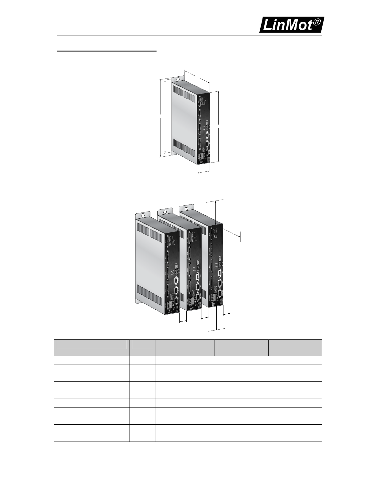
Mechanical Dimension
Dimensions
Centers
315
296
330
60
178
Fixings for 2 x M5 screws
dimensions in mm
Recommended mounting for multiple controller installations
20
20
100
dimensions in mm
100
20
100
E1031
Single axes controller
E2031
2 axes controller
E4031
4 axes controller
Width mm (in) 60 (2.4)
Height mm (in) 330 (13)
Height without fixings mm (in) 296 (11.7)
Depth mm (in) 178 (7)
Weight Kg (lb) 2.5 (5.5)
Case IP 20
Storage Temperature °C -25…40
Transport Temperature °C -25..70
Operating Temperature °C 0…40
Max. Case Temperature °C 65
Page 11
Controller Series E1031/2031/4031 V3
NTI AG Installation: E1031/E2031/E4031 V3 series / 28.07.2010 Page 11/17
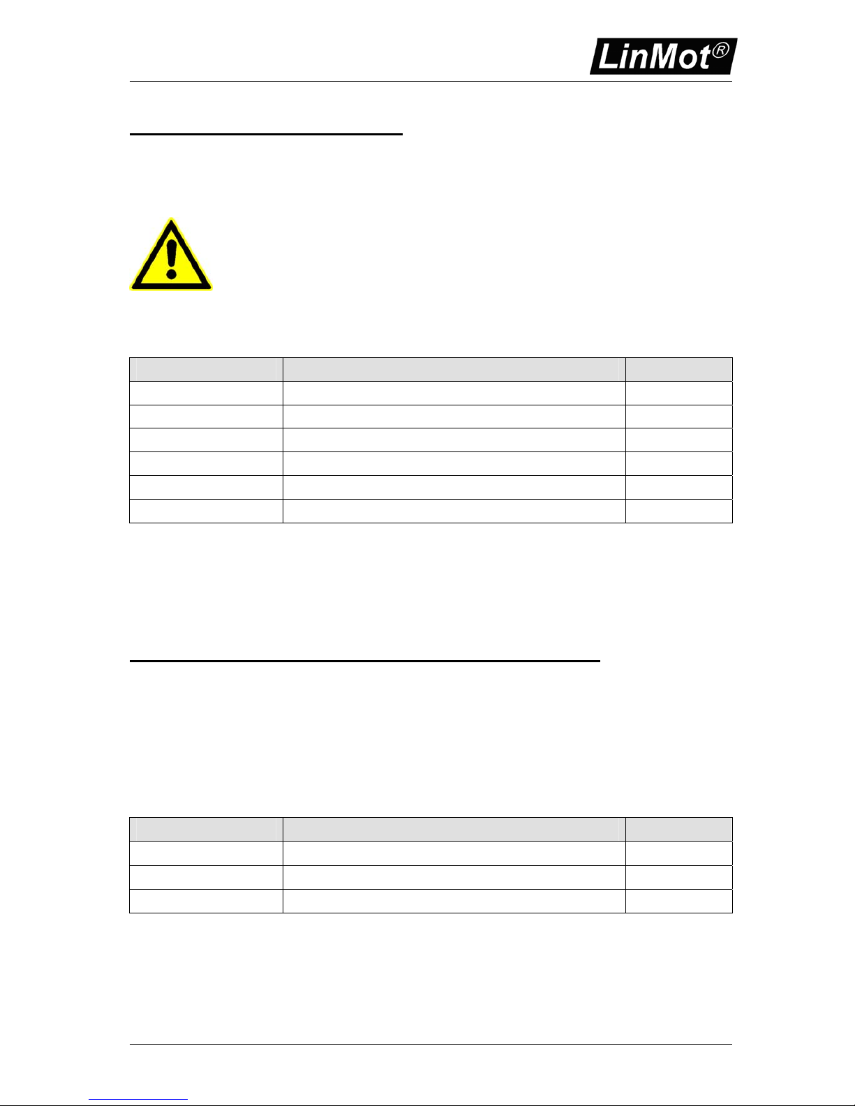
Power Supply Requirement
Power Supply motor
The calculation of the needed power for the motor supply depends on the application and the used
motor. The nominal supply voltage is 72 VDC. The possible range is from 24…85VDC.
ATTENTION: The motor supply can rise up to 95 VDC when braking. This means
that everything connected to that power supply needs a voltage rating of 100 VDC.
(Power supply itself, additional capacitors, etc…)
For the same reason, the 24VDC supply for the signal, shall not be connected
together with the motor supply. If the motor is supplied with 24 VDC, this must be an
additional, independent power supply.
Recommended Power supplies:
Item Description Art. No.
T01-72/420 72VDC, 15A peak, 420VA, 3x400VAC 0150-1966
T01-72/420-US 72VDC, 15A peak, 420VA, 3x230VAC 0150-1967
T01-72/900 72VDC, 30A peak, 900VA, 3x400VAC 0150-1842
T01-72/900-US 72VDC, 30A peak, 900VA, 3x230VAC 0150-1843
T01-72/1500 72VDC, 2x30A peak, 1500VA, 3x400VAC 0150-1844
T01-72/1500-US 72VDC, 2x30A peak, 1500VA, 3x230VAC 0150-1845
Power Supply signal
The logic supply needs a regulated power supply of a nominal voltage of 24 VDC. The voltage must
be between 22 and 48DC.
Power consumption: 10W
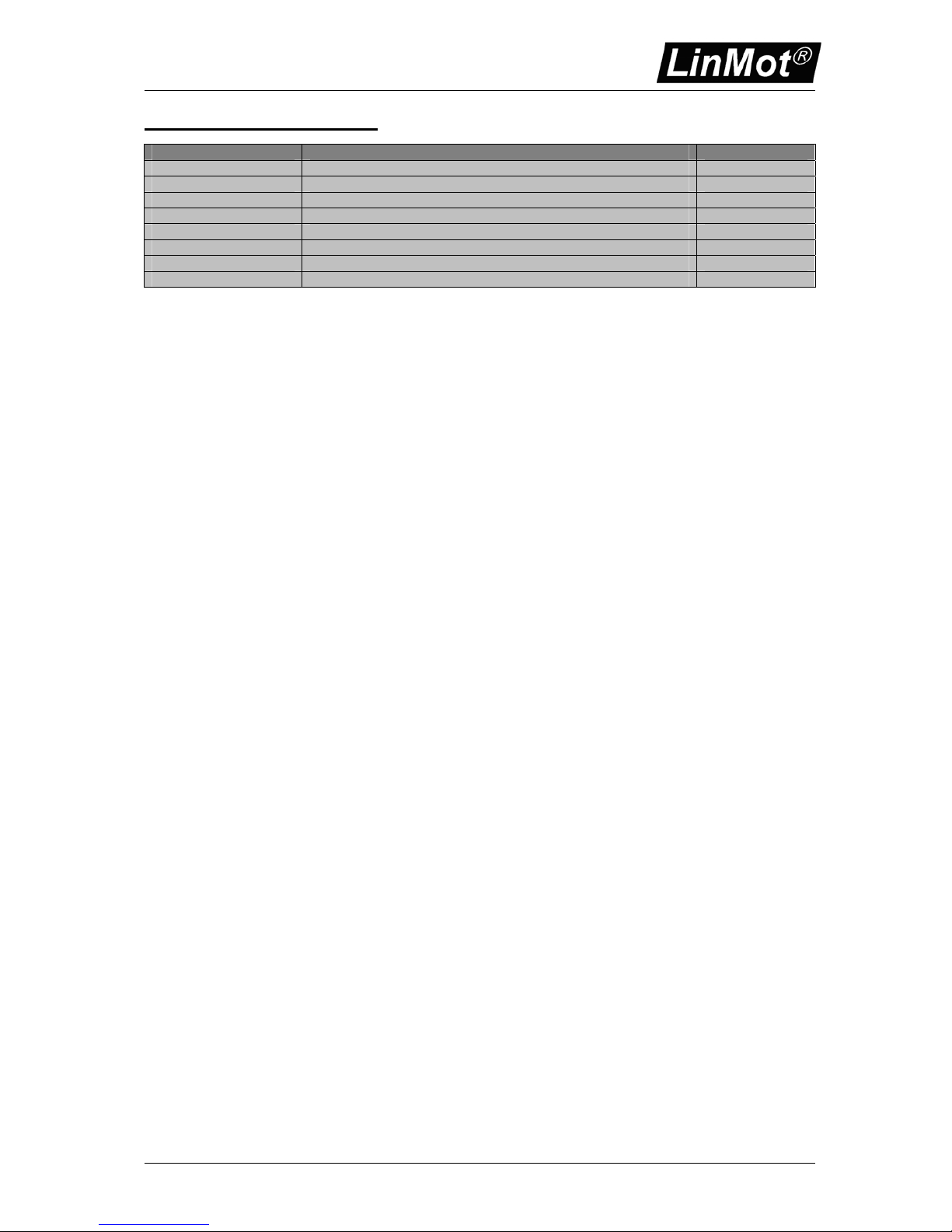
Regeneration of Power / Regeneration Resistor
There are two possibilities handle power regeneration:
Option A: Connect an additional capacitor to the motor power supply. It is recommended to use
a capacitor >= 10’000 μF (install capacitor close to the power supply!)
Option B: Install a Regeneration Resistor to X1 (RR+ and RR-). The threshold value of the
voltage depends on the used motor voltage power supply. The max. threshold value
must not exceed 88 VDC.
Item Description Art. No.
Capacitor
Capacitor 10’000 μF / 100 V
0150-3075
Regeneration Resistor RR01-10/60 (10 Ohm, 60 W) 0150-3088
Regeneration Resistor RR01-10/150 (10 Ohm, 150 W) 0150-3090
Page 12
Controller Series E1031/2031/4031 V3
NTI AG Installation: E1031/E2031/E4031 V3 series / 28.07.2010 Page 12/17
Ordering Information
Servo Controller Description Art. No.
E1031-DP Profibus DP Controller 1 Axis (72V/8A) 0150-2316
E1031-DP-ME Profibus DP Controller 1 Axis (72V/8A) with integrated ME 0150-2336
E2031-DP Profibus DP Controller 2 Axis (72V/8A) 0150-2317
E2031-DP-ME Profibus DP Controller 2 Axis (72V/8A) with integrated ME 0150-2337
E4031-DP Profibus DP Controller 4 Axis (72V/8A) 0150-2319
E4031-DP-ME Profibus DP Controller 4 Axis (72V/8A) with integrated ME 0150-2339
Page 13
Controller Series E1031/2031/4031 V3
NTI AG Installation: E1031/E2031/E4031 V3 series / 28.07.2010 Page 13/17
Declaration of Conformity CE-Marking
Manufacturer: NTI AG
LinMot
®
Haerdlistrasse 15
CH-8957 Spreitenbach
Switzerland
Tel.: +41 (0)56 419 91 91
Fax: +41 (0)56 419 91 92
Products: LinMot
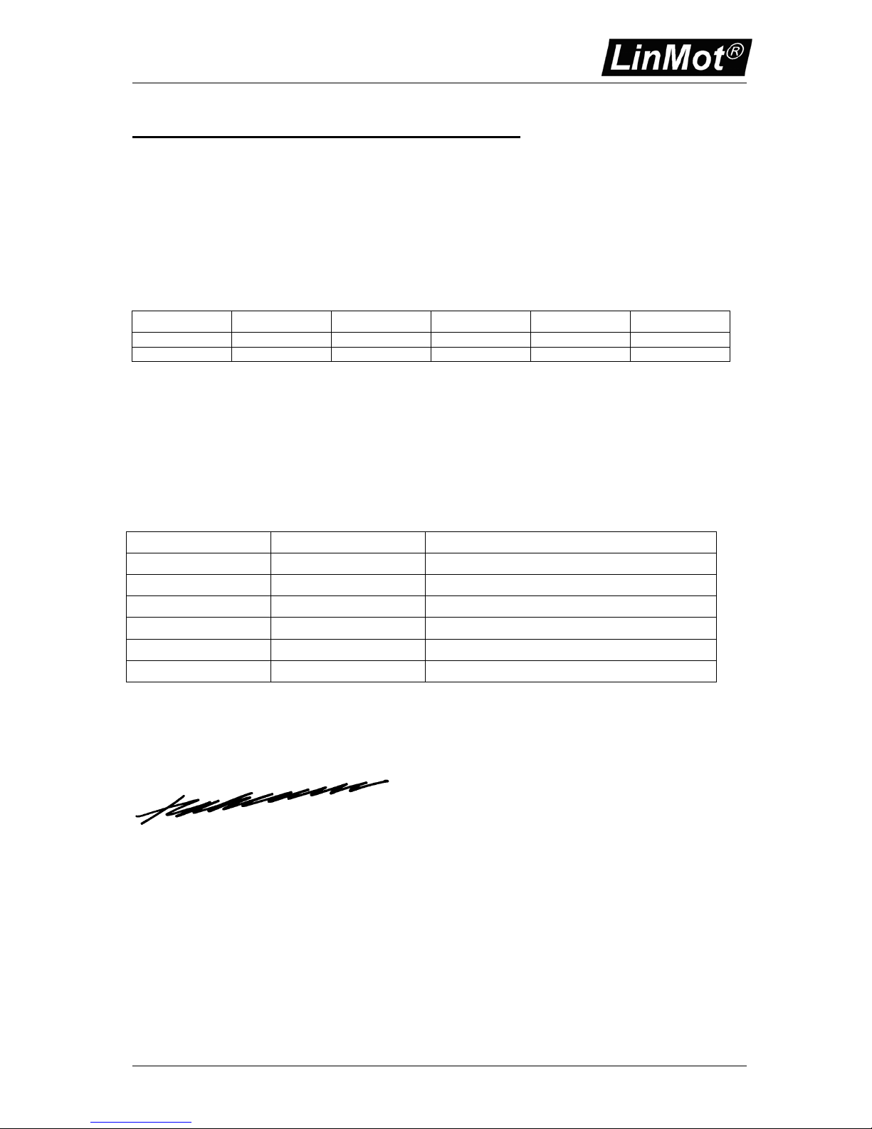
®
Controllers E1001 series
Type Art.-No. Type Art-No. Type Art.-No.
E1031-DP 0150-2316 E2031-DP 0150-2317 E4031-DP 0150-2319
E1031-DP-ME 0150-2336 E2031-DP-ME 0150-2337 E4031-DP-ME 0150-2339
The product must be mounted and used in strict accordance with the installation instruction contained
within the User’s Manual, a copy of which may be obtained from NTI AG.
I declare that as the authorized representative, the above information in relation to the
supply/manufacture of this product is in conformity with the stated standards and other related
documents in compliance with the protection requirements of the Electromagnetic Compatibility (EMC)
Directive 2004/108/EC.
Standards Complied with:
EMI EN 55011 Class A
EN 61000-6-4
Electromagnetic EN 61000-4-2 4 kV / 8kV
Susceptibility EMC EN 61000-4-4 1 kV / 2kV
EN 61000-6-2 EN 61000-4-3 10 V/m
EN 61000-4-6 10 V
ENV 50204 10 V/m
Company
NTI AG
Spreitenbach, July 28, 2010
----------------------------------------------------------R. Rohner / CEO NTI AG
Page 14
Controller Series E1031/2031/4031 V3
NTI AG Installation: E1031/E2031/E4031 V3 series / 28.07.2010 Page 14/17
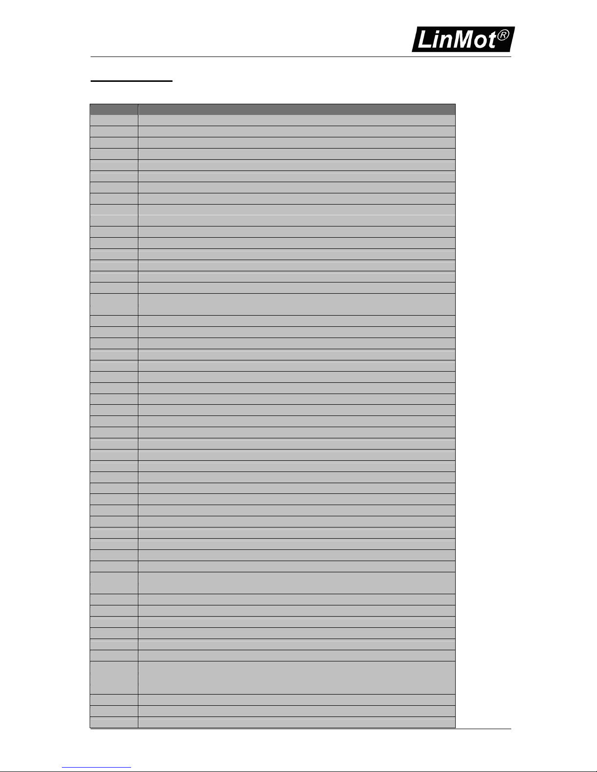
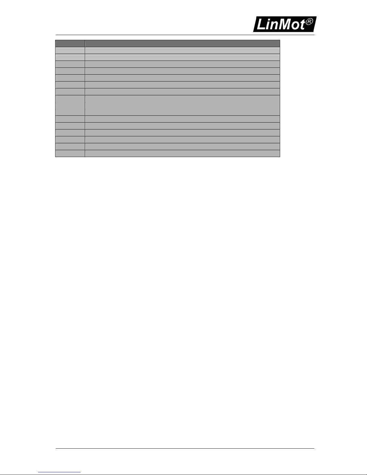
Error codes
In the Error State the controller displays the error code by the 7-segment display:
Code Description
E0001 Missing or invalid parameter tree
E0002 Missing or invalid application
E0003 Controller type not supported
E0004 MT command interface not available
E0005 Timer watchdog error
E0006 Trap class A error
E0007 Trap class B error
E0008 No master found for slave motor.
E0009 No external sensor defined
E000A External sensor not allowed on channel D
E000B The application software needs an MT Electronics
E000C Noise Dead Band is not supported on this device revision (must be set to 0mm)
E0010 DCLV Power Too Low
E0011 DCLV Power Too High
E0012 DCLV Signal Too Low
E0013 DCLV Signal Too High
E0014 Electronic Fault
E0015 HW Error Internal 12V missing
E0101 Drive A Too Hot Calculated
E0102 Drive A Too Hot Sensor
E0103 Drive A Following Error
E0104 Drive A Slider Missing
E0106 Drive A Init Failed
E0107 Drive A Drive Type Mismatch
E0108 Drive A Curve Error
E0109 Drive A: Board Over Current
E010A Drive A: Board Over Temperature
E010B Drive A: AGND or 5VDC Fuse Blown
E0201 Drive B Too Hot Calculated
E0202 Drive B Too Hot Sensor
E0203 Drive B Following Error
E0204 Drive B Slider Missing
E0206 Drive B Init Failed
E0207 Drive B Drive Type Mismatch
E0208 Drive B Curve Error
E0209 Drive B: Board Over Current
E020A Drive B: Board Over Temperature
E020B Drive B: AGND or 5VDC Fuse Blown
E0301 Drive C Too Hot Calculated
E0302 Drive C Too Hot Sensor
E0303 Drive C Following Error
E0304 Drive C Slider Missing
E0306 Drive C Init Failed
E0307 Drive C Drive Type Mismatch
E0308 Drive C Curve Error
E0309 Drive C: Board Over Current
E030A Drive C: Board Over Temperature
E030B Drive C: AGND or 5VDC Fuse Blown
E0401 Drive D Too Hot Calculated
E0402 Drive D Too Hot Sensor
E0403 Drive D Following Error
E0404 Drive D Slider Missing
E0406 Drive D Init Failed
E0407 Drive D Drive Type Mismatch
E0408 Drive D Curve Error
Page 15
Controller Series E1031/2031/4031 V3
NTI AG Installation: E1031/E2031/E4031 V3 series / 28.07.2010 Page 15/17
Code Description
E0409 Drive D: Board Over Current
E040A Drive D: Board Over Temperature
E040B Drive D: AGND or 5VDC Fuse Blown
$FFEC RAM error
E1001 RTS: State is too long
E1002 RTS: Controller version not supported
E1003 RTS: Wrong firmware
E1004 RTS: No script found
E1005 RTS: Illegal command
E8000 Profibus DP: Connection to master lost
E8001 Profibus DP: Address not valid
E8002 Profibus DP: Data out of range
E8003 Profibus DP: Invalid configuration from PLC
Page 16
Controller Series E1031/2031/4031 V3
NTI AG Installation: E1031/E2031/E4031 V3 series / 28.07.2010 Page 16/17
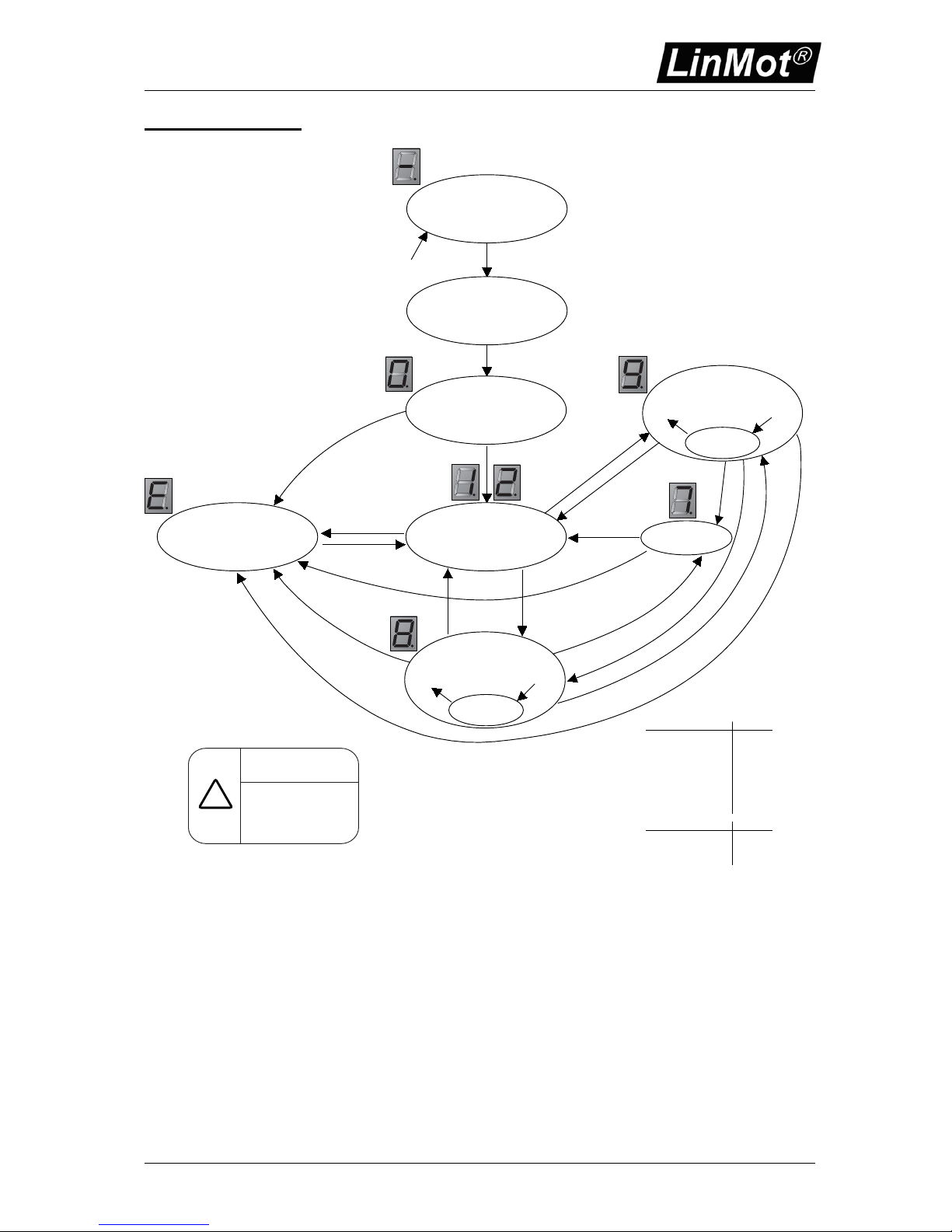
State Machine
RUN (8)
STOP (7)
FREEZE
DISABLE (1)
((2)if INIT DONE
ERROR
(Exxx)
WAIT FOR
DISABLE (0)
DRIVE INIT (9)
FREEZE
SETUP
IR
!IR
SR
!RR & !IR & !SR
SR
EP
EP
EP
!EP & !RR & !IR & !SR
EP
RR & !DIND & !WP
!RR
RR & !DIND &!WP & !IR
!RR & IR
FR!FR
EP
FR!FR
!RR & !IR & !SR
i
Input signals have to be
activated in the parameter
tree!
RUN signal is set in state
SETUP. For changing into the
state DISABLE, the RUN
signal must be cleared from
the active interface!
Input Signals Abbreviation
Set INIT Request IR
Set RUN Request RR
Set STOP Request SR
Set FREEZE Request FR
Reset INIT Request !IR
Reset RUN Request !RR
Reset STOP Request !SR
Reset FREEZE Request !FR
Internal Signals Abbreviation
DRIVE_INIT_NOT_DONE DIND
ERROR_PENDING EP
WARNING_PENDING WP
FIRMWARE
STOPPED (-)
Power Up | Start Firmware
Power Down | Stop Firmware
Page 17

Controller Series E1031/2031/4031 V3
NTI AG Installation: E1031/E2031/E4031 V3 series / 28.07.2010 Page 17/17
Contact Addresses
----------------------------------------------------------------------------------------------------------------------------SWITZERLAND NTI AG
Haerdlistr. 15
CH-8957 Spreitenbach
Sales and Administration: +41-(0)56-419 91 91
office@linmot.com
Tech. Support: +41-(0)56-544 71 00
Tech. Support (Skype) : skype:support.linmot
Fax: +41-(0)56-419 91 92
Web: http://www.linmot.com/
----------------------------------------------------------------------------------------------------------------------------USA LinMot, Inc.
5750 Townline Road
Elkhorn, WI 53121
Sales and Administration: 877-546-3270
262-743-2555
Tech. Support: 877-804-0718
262-743-1284
Fax: 800-463-8708
262-723-6688
E-Mail: [email protected]
Web: http://www.linmot-usa.com/
-----------------------------------------------------------------------------------------------------------------------------
Please visit http://www.linmot.com/ to find the distribution near you.
Smart solutions are…
 Loading...