

Page 1

1
OPERATION MANUAL
2001 is a VHF / FM transceiver designed for use in the frequency
range of 156.000 to 163.275 MHz on the USA and International Marine Channels
This transceiver is sold for purposes of marine communications only. As with all
wireless devices, its performance may be degraded by environmental conditions,
static, interference or circuit failure. Other equipment is available for marine
ation and safety, and communications should never be relied on for these
The manufacturer of the equipment
peration Manual
to enable you to record the model and serial numbers of the equipment and to provide
you with a description of the location of such numbers on the equipment. When you
hould retain
SEALAB – LT2001
VHF Marine Radiotelephone
Ä
All U.S. and International Channels
Ä
Including 10 weather Channels
Ä
Channel 16 priority key
Ä
Full 25 Walt
Ä
13/67 easy switch LOW / HI power
Ä
Full and 10 menu channel scanning
Ä
Water – resistant, soft-touch key switches
Ä
IMPORTANT
The Link Tech., LT
LINK TECH
COMMUNICATIONS
EXHIBIT : 7
indicated.
navig
important marine procedures.
In compliance with certain state laws. Link Tech.
you have purchased, is required to provide suitable space in your O
have entered the required information in the spaces provided below, you s
the manual so that you have a permanent record of the model and serial numbers.
Unit description:
Model No.:
(Located on the rear of the unit)
Serial No.:
(Located on the rear of the unit)
Page 2

2
The Model LT2001 complies with all United States Federal Communications
Commission, Canadian Department of Communications and United Kingdom Radio
Communications Agency regulations for maritime radio services. The user is
edgeable concerning and comply with all rules and regulations of
the maritime radio service for the country in which the operating license is issued and
in the countries where the transceiver may be used. Rules and regulations may be
The user must obtain a license and call sign from the appropriate regulatory
United States
plication (FCC 506) must
include a fee of $35.00 payable to the FCC in the form of a single check or
1. REGULATORY INFORMATION
required to be knowl
obtained from the regulatory authority or printing office in each country.
RULES AND REGULATIONS
United States Superintendent of Documents
Government Printing Office
Washington, DC 20402
Canada Regional Offices
Atlantic Regional Office
4th Floor
1045 Main Street
P.O. Box N.B.
Moncton, N.B.
E1C 8R2
(506) 851- 6525
Ontario Regional Office
9th Floor
55 St. Clair Ave., East
Toronto, Ont.
M4T 1M2
(416) 973- 8215
Prairies and Northwest
Territories Regional Office
Room 200
386 Broadway Ave.
Quebec Regional Office
Suite 306
715 Peel Street
Montreal, Quebec
HSC 4S2
(514) 283- 2307
B.C./Yukon Regional Office
Suite 1700
800 Burrard Street
V6Z 2J7
(604) 666- 5468
United Kingdom
Marine Licensing Section
Radio Regulatory Division
Waterloo Bridge House
Waterloo Road
London, England SE1 8UA
Winnipeg, Man.
R3C SY9
(204) 983- 3182
1. LICENSE APPLICATIONS
authority. Contact your local authorities for applications forms.
Effective May 21, 1990, each Ship Radio Station Ap
Page 3

3
money order. Approximately May 1, 1994, the license processing fee will
increase to about $45.00 and an additional $70.00 for a 10 year License fee will
The following date pertaining to the LT2001 is helpful when filling out your FCC
EXEMPTIONS: Applicants filing as a Governmental Entity do not require a fee, and
e Fleet licenses must
compute their application fee by multiplying the number of ship in the Fleet by
$35.00. For Fleet license modification applications, compute the fee by multiplying
to be added
Questions about fees may be directed to the FCC’S Private Radio Bureau Consumer
The following data pertaining to the LT2001 is helpful when filling out your FCC
Distress and safety communications must have absolute priority over other kinds of
be required. DO NOT SEND CASH. Send application to:
Federal Communications Commission
Marine Ship Service
PO Box 358275
license application:
should send their application to:
Federal Communications Commission
Pittsburgh, PA 15251-5275
1270 Fairfield Rd.
Gettysburg, PA 17325- 7245
FLEET APPLICANTS: Applicants for new and renewed Marin
the number of stations to be modified by $35.00. When adding stations
by $35.00.
Assistance Branch, Gettysbury, PA, phone (717) 337- 1212.
Other FCC Information:
The LT2001 radiotelephone meets all applicable sections of FCC Rules Part 80.
license application:
Type acceptance
Out put Power
Frequency Range
Emission Designator
FCC ID
FCC Part 80
1 Watt low and 25 watts high
156.000 to 162.000 MHz
16KOG3E
PS2 VMR2001A
The operator is at all times responsible for the lawful operation of the radio.
ship-to-ship or ship- to-shore calls.
The FCC does not allow any of the following to be transmitted from your radios:
Message using obscene, indecent, or profane language
False distress or emergency messages
Messages from a boat on land such as a trailer.
Page 4

4
tion Number
als for possible
INSTALLATION
Choose a location for your radio that is free from direct water spray, Rain and
direct sunlight. If the radio is mounted in a location subject to extreme vibration
hock mount must be used. Allow
sufficient room behind your radio for cables to be installed and do not install the
unit too close to the compass. The “Compass Safe Distance” should be 12 to
Canadian Regional Offices
Atlantic Regional Office
4th Floor
1045 Main Street
P.O. Box N.B.
Moncton, N.B.
E1C 8R2
(506) 851- 6525
Ontario Regional Office
9th Floor
55 St. Clair Ave., East
Toronto, Ont.
M4T 1M2
(416) 973- 8215
Prairies and Northwest
Quebec Regional Office
Suite 306
715 Peel Street
Montreal, Quebec
HSC 4S2
(514) 283- 2307
B.C./Yuko Regional Office
Suite 1700
800 Burrard Street
Vancouver, B.C.
V6Z 2J7
(604) 666- 5468
Territories Regional Office
Room 200
386 Broadway Ave.
Winnipeg, Man.
R3C SY9
(204) 983- 3182
Canadian Certifica
477822104V
2. UNPACKING
Equipment Supplied
Radio
Mounting Bracket
Two mounting Knobs
Microphone
Microphone hanger clip
Power cord with fuse
Instruction Manual
Warranty Card
License Application form for USA
Unpack all items carefully. Retain the carton all packing materi
future use.
3.
or pounding when running, a suitable s
Page 5

5
15 inches.
Use VHF marine antenna, which has the 50 ohm impedance and the correct
be mounted as high as possible for maximum range.
Connect the antenna connector to the corresponding connector on the back of
the radio, using a 50 ohm coaxial cable with a PL 259 connector. Do not cut or
he VSWR and could damage
your unit. LT manufactures an complete line of VHF antennas that are perfectly
matched and tuned to the LT2001. IMPORTANT: Do not attempt to transmit
without an antenna (or with an improper antenna) connected. This may cause
This unit operates from a 12 volt. negative ground electrical system. Do not
attempt to use it in a positive ground system. The DC power cable supplied is
oat battery. Choose a
point which is able to handle at least 6 amps. Your best location would be the
switched side of your ignition switch. If you must extend the power leads, keep
wiring as short as possible, since long wires can reduce the transmitter
rformance. Use #10 wire size for up to 10feet and size #8 for up to 25 feet.
Be sure to connect the red (fused) lead to the positive terminal and the black to
) or ground. The radio is equipped with “reverse polarity protection.” This
lly blow the fuse, thus protecting the unit from harm if the
polarity should be reversed during installation. If the fuse should blow,
check your battery connections. Always
ting. Replacement with a higher
king use of the
EXT SP jack on the rear panel. Connect the external speaker designed of this
3.1 Mounting Bracket
The mounting bracket may be used for base or gimbals type overhead
mounting.
Secure the bracket to the mounting surface by using at least four Screws.
3.2 Antenna Connection
termination. It should
shorten your antenna lead wire, as it will effect t
permanent damage to your radio.
3.3 Power Connection
used to make the necessary DC connection to your b
pe
the (-
will automatica
immediately turn off the radio and re-
replace the fuse with one having the same ra
rated fuse could cause damage to the radio.
3.4 Microphone Connection
Microphone supplied with the radio on the front panel.
3.5 External Speaker Connection
The radio can be used with an external speaker system by ma
purpose.
3.6 Factory Preset For 1 st Switch On
USA Version USA Channel
Intl Version Intl Channel
French Version Intl Channel
CH 39 On/OFF
3.7 Reception
Page 6

6
A. Set Squelch control fully counter clockwise.
With no signal received, turn squelch clockwise until background noise is just
alk button (PTT) and speak into microphone at a distance of
Do not use the international emergency signal “MAYDAY” unless there is
When you expect a reply, end your transmission with the word, “OVER.” If you
Always release PTT immediately after each transmission. A timer restricts the
signed to meet the
Talk switch is
ll begin operating in the following
Push to talk (transmit) switch and Channels 13/67 Override
Pushing in this rubber covered PTT button switch activates the transmit (talk)
During operation on channels 13 or 67, the FCC requires that your transmitter
power is automatically limited to 1 watt. Your radio is equipped with this limiting
If it becomes necessary in an emergency to be heard, you may override this
B. Turn On/Off volume control on and set volume on background noise.
C.
quiet.
D. Select mode of operation and/or select channel.
3.8 Transmission
A. Select mode of operation and/or channel.
B. Monitor channel to make certain it is not in use by others.
C. Select power-High or Low - (Some channels are fixed at low power.)
D. Press Push to t
approximately one (1) inch.
E.
immediate danger to property or loss of life.
F. Call other vessels by name or “call sign.”
G.
are finished use the word, “OUT.”
H.
length of any transmission to 5 minutes. The LT2001 is de
new FCC Rules Part 80.203. which states, if the Push- TO-
pressed for over 5 minutes continuously, transmission is forcibly inhibited.
4.0 OPERATING CONTROLS AND FUNCTIONS
When your transceiver is first turned on, it wi
condition:
1. All liquid crystal display segments are lighted up (indicated) for about 1 second.
2. Normal channel model, Channel 01.
3. Programmable memory (10 Channel Scan) erased.
4. Weather Channel 01.
5. Transmissions power 25 watts (when battery is fully charged).
6. Scan/dual/tri watch and M Channel functions are deactivated.
7. USA/Intl. Channel selection is USA.
4.1 Volume Control (ON/OFF)
Turns radio on/off and controls audio volume of speaker.
4.2 Squelch Control
Adjusts input signal level so as to quiet background noise.
4.3
function of the transceiver.
feature.
Page 7

7
featur
e by depressing and holding the override switch of microphone. Pushing
in the button marked 13/67. Will increase power form 1 watt to 25 watts on
Channels 13 and 67 only. Pushing the PTT button will suspend all receiving
mission will occur on channel shown at
instant PTT is pushed. Upon release of PTT, receive function will resume and
scanning functions will resume 5 seconds after no signal is received. PTT will
hannels in program model. (If PTT key is pushed during the time a signal is
a short beep tone will sound.) Transmission may continue. (If
PTT is pressed continuously for 5 minutes, 3 short beep tones will be heard
The Keypad has various keys (push buttons) which control the functions of the
Pressing the USA/International key will select either USA or International
channel. USA or International will be indicated on the liquid crystal display.
88. International channels include
88, M0, M1, and M2. M1 and M2 are not authorized
Pressing the normal key allows any USA / Intl. Channel to be selected by
resetting the up or down keys. One press will raise or lower the channel
number by 1. Holding either the up or down key for more than 1.5 seconds will
hannel selection process to 4 steps per second. Channel
With transceiver in normal model, normal key pressed and normal indicated,
to activate scanning. Transceiver will scan all channels in
either USA or International list. (M0, M1, M2 cannot be scanned). They can be
selected manually in normal model. “Scan” will be indicated on liquid crystal
functions including scanning. Trans
not operate if transceiver is on weather or vacant (null)
C
being received,
and transmission will be terminated until PTT is released and repressed.)
4.4 Keypad
transceiver.
A. USA/International
USA channels include 01-28, 60- 74, 7701 -28, 37, 39, 60-74, 77for use in USA waters.
B. High or Low power
speed up the c
number will be indication on LCD.
C. Normal All Channel Scanning
press “scan” key
display.
Page 8

8
During all channel scan if “sca
n” key is pressed again, scanning will stop on
indicated channel. “Scan” indication will disappear from liquid crystal display. If
the transceiver hears a signal the scanning function will cease and the receiver
ds minimum or as long as the signal
continues. During this stop scan period, the scanning function can be
suspended by pressing the “scan” key again. The scan indication will flash
l key to terminate scanning. The normal channel is recovered from
When the all channel “scan” mode is selected, the squelch control should be
ion). This will avoid
the scan function stopping on a channel where interference or a week and
Press key “16” to immediately access. Channel 16 will be indicated on LCD.
nnel functions will be cancelled. Press
Press “WX” key to access weather channel mode. WOX is indicated on LCD.
Press “up” or “down” key to select the desired weather channel. Total 10
Press “normal” key to terminate the weather channel function and return back
“M” key to activate M channel function. “M” indicator is shown. Channel
to exit from M channel mode. NOTE: Dual Watch and Tri
Press normal key and select any channel you may wish to scan, with Channel
l will be indicated on the
When hearing a signal on either channel, Dual Watch will be suspended for a
Tri Watch Mode
Press normal key and select one channel to be Tri watched (scanned). Press,
and hold for 1.5 seconds, program key and select one more channel to be Tri
then press Tri. Tri will be indicated on
LCD. The two channel selected above will be Tri watched (Scanned) together
When hearing a signal on any of these three (3) channels, the Tri watch
will stay on that channel for four (4) secon
continuously. Press scan key once again to reactivate scanning.
Press norma
memory and shown on the liquid crystal display.
adjusted fully clockwise (instead of just past first silent posit
unintelligible signal may exist.
D. Channel 16
Dual, Tri, All Scan and Weather Cha
normal key to terminate Channel 16 function and return to normal channel.
E. Weather Channels
When first turned on the weather channel is 01.
weather channel (from 00 to 99) are available.
to normal channel function.
F. M Channels Mode
Press
number show “00.”
Press “M” key again to access next M channel. Channel number shows “01.
Press “M” key again will access M2 channel and then cycle back to M0.
Press “normal” button
Watch functions can be can be used in M channels mode.
G. Dual Watch Mode
LCD. Dual Watch can only be selected when transceiver is in normal mode.
minimum of 5 seconds or as long as the received signal continues.
16, in the dual watch mode. Press Dual Watch. Dua
Press Dual key again or normal key to terminate Dual function.
H.
watched (scanned). Press normal and
with Channel 16.
Page 9

9
scanning will be suspended for a minimum of 5 secon
ds or as long as the
Press and hold Prog. key for 1.5 seconds to access 10 Channel Priority
Press up or down key again to select first channel to be
Press Prog key again for 1.5 seconds, to access second priority channel
Programmed priority channels may now be manually selected by pressing the
To scan up to 10 programmed priority channels, press Scan key after Prog key
has been pressed and programming completed. Scan will be indicated on
During programmed priority channel scan if scan key pressed again, scanning
will stop on indicated channel. Scan indication will disappear from liquid crystal
eiver hears a signal the scanning function will cease and the
receiver will stay on that channel for four (4) seconds minimum or as long as
the signal continues. During this stop scan period, the scanning function can
again. The scan indication will flash
Press normal key to terminate scanning. The normal channel is recovered from
be set up using one of the above programmed
priority channels (number 1) and Channel 16. Proceed as in normal Dual
itched off.
The programmed channels can be recalled and accessible next time when the unit is
However, if the power connection is disconnected, the memory retention function will
isconnected from its power
received signal continues.
Press Tri key again or normal key to terminate Tri watch function.
I. Programmed Priority 10 Channel Scanning Mode
scanned. Hold up or down key for 1.5 seconds for fast selection of channel.
selection mode. Ten (10) priority channels are selectable.
Prog Key. Program numbers 1 through 10 and Channel Numbers will be shown
Programming Mode.
as selected or scanned.
LCD.
display.
If the transc
be suspended by pressing the scan key
continuously. Press scan key once again to reactivate scanning.
memory and shown on the liquid crystal display.
Dual Watch scanning may also
Watch (with transceiver in Prog mode.
Memory Retention Function
The unit automatically stores all user- programmed channels when it is sw
switched on.
hold for 1 minute only: the unit will lose its memory if it is d
source for more than 1 minute.
4.5 Key Lock Mode
Press lock key to lock all functions except:
A. PTT function
B. CH 13/67 Override function
C. CH 16 button
D. H
E. Hi / Lo button
Page 10

10
5.0 Power Connector (13.6 VDC)
ower to operate the unit is fed through this connector using DC power
This jack is used for connection to an external speaker (optional accessory.)
in
This jack accepts the antenna connector. The antenna must be connected
After contact is established, arrange to meet one anther on ship to ship
ng of
other vessels, the FCC has approved channel 9 as a second hailing
by regulation, can only concern navigation at
docks and bridges. Transmission on Channel 13 is automatically limited to low
power. However, in emergencies or blind river bends, pushing the 13/67
limitations are in accordance with USA regulations ONLY. Authorized use and
Communications on Channel 67, by regulation, can only concern
etween ships. Pushing the override portion
of the PTT can temporarily use high power. Use and power limitations are in
accordance with USA regulations ONLY. Authorized use and power may vary
Use a channel which is assigned for this purpose. After contact is made,
identify and ask the operator to connect you to the telephone lines. Charges
DC p
cable supplied.
5.1 External Speaker Jack
speaker.
5.2 Antenna Connector
before transmitting, otherwise the radio could be seriously damaged.
6.1 Hide For Operate To Call Anther Vessel
A. Select Channel 16 (Be sure it is not in use)
B. Call vessel by name or “call sign.”
C. End transmission with “OVER.”
D.
Insertion of the speaker plug in this jack automatically silences the built-
channel
NOTE: Due to congestion on channel 16 caused by frequent haili
channel.
Avoid excessive calling and radio checks
Always monitor before transmitting
Never interrupt emergency communications
6.2 Channel 13 Operation
Communications on Channel 13,
override portion of the PTT will raise the power to 25 watts. Use and power
power may vary in other countries.
6.3 Channel 67 Operations
bridge-to-bridge navigation traffic b
in other countries.
6.4 Calling the Marine Operator For Telephone Calls
vary for this service. (See list for ship to shore Channels.)
Page 11

is mainly used by Marine Telephone Operators. A duplex channel
ship communication because the transmit and
receive frequencies are not the same. Example CH 24 157.200 MHz transmit
l channels are factory programmed in accordance with FCC (USA) and IC
(Canada), and International regulations. Mode of operation cannot be altered from
caused
by unauthorized modifications to this equipment. Such modifications could
6.5
A. A simplex channel is used for ship- to-ship communication. The transmit
B. A duplex channel is a public correspondence, ship-to-coast channel
NOTE:
Simplex/Duplex Channe l Use
And receive frequencies are the same.
Example: CH 22A 157.000 MHz, transmit & receive (USA mode)
Which
cannot be used for ship-to-
and 161.800 MHz receive, (USA mode.)
Al
simplex to duplex or vice-versa.
“The manufacturer is not responsible for any radio or TV interference
void the user’s authority to operate the equipment.”
7. SPECIFICATIONS
A. General
Frequency Range: 156.0 to 1562.550 MHz
Input Voltage: 9.0 – 13.6V DC
Dimensions: H2 1/3” X W6 1/3” X D8”
Operating Temperature: -20 to + 60
Frequency Stability: +/- 10PPM
B.
Receiver
11
Page 12
12
Receiver Section: -6DB 12DB SINAD
Link Tech products are maintained by highly skilled and trained technical
connected to the POSITIVE battery
the DC power cables away
Usable Sensitivity: - 6DB 20DB QUETING
Squelch Sensitivity:
Threshold: - 12DB Full Squelch Tight: -3DB
Adjacent Channel Rejection: 60DB FCC, 70DB MPT
Spurious and Image Rejection: 60DB
Intermediate Frequencies
10.7 MHz
First I.F.: 21.6 MHz
Second I.F.: 455 KHz
Audio Output (fully charged): 1.2W MAX 2W
Hum and Noise: - 40DB
Audio Distortion: 5%
Current Drain
At Standby: 200mA
C. Transmitter
R.F. Output
At 13.4V: 25Watts
(Hi Power Setting) (Limited to 1 Watt at Lo Power Setting)
Conducted Spurious Emissions: -50DB
Modulation Deviation: ± 5 KHz
Current Drain
At Hi Power 25W: 6A
At Lo Power 1W: 450mA
8. MAINTENANCE
personnel using the latest electronic equipment.
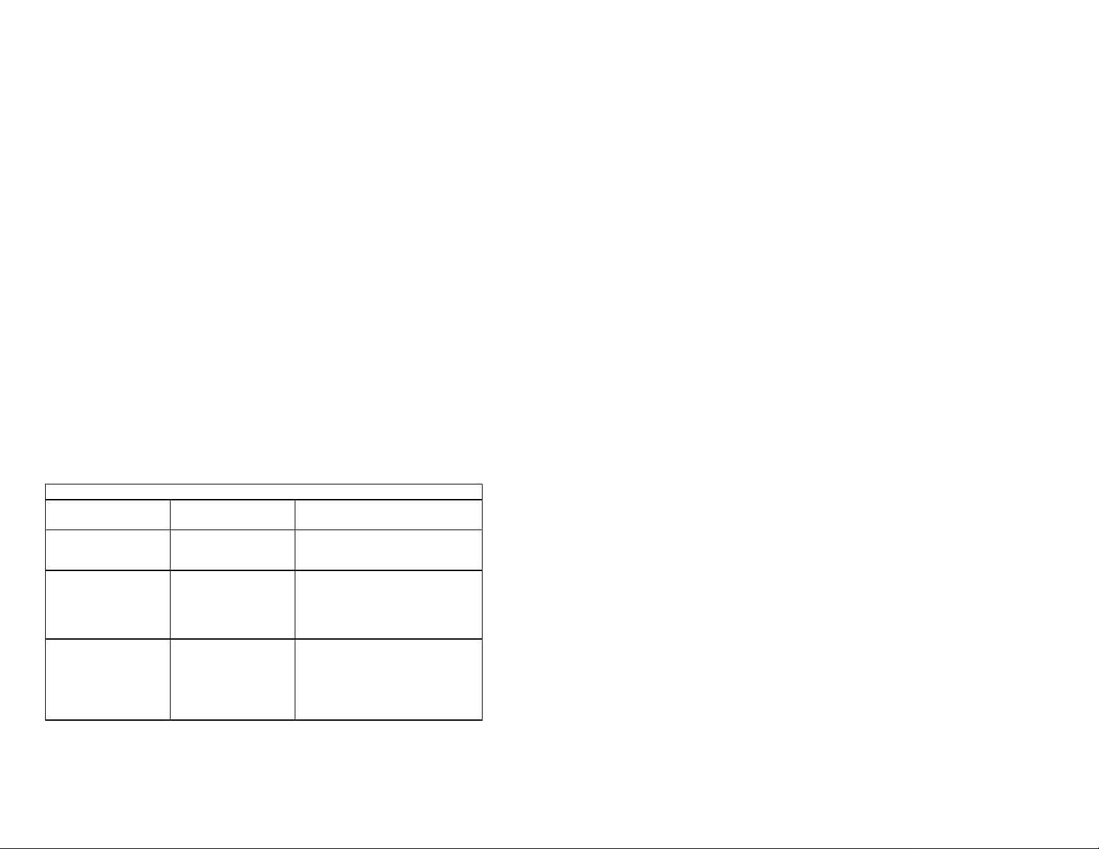
TROUBLESHOOTING CHART
SYMPTOM PROBABLE
CAUSE
Radio fails to power UP No DC voltage to the
Radio blows fuse upon
connection to power
supply
Popping or whining
noise from the speaker
while the engine runs.
radio or blown fuse
Reversed power
connections.
Engine Noise. Reroute
REMEDY
Check power cable for DC voltage
or replace the 7A fuse with length
31.8mm, diameter 6.35mm
Make sure the RED wire is
terminal and the BLACK wire is
connected to NEGATIVE. If radio,
contact LT for service.
from the engine. Add noise
suppressor on power cable.
Change to resistive spark plug
wires and/or add an alternator
whine filter.
Page 13
13
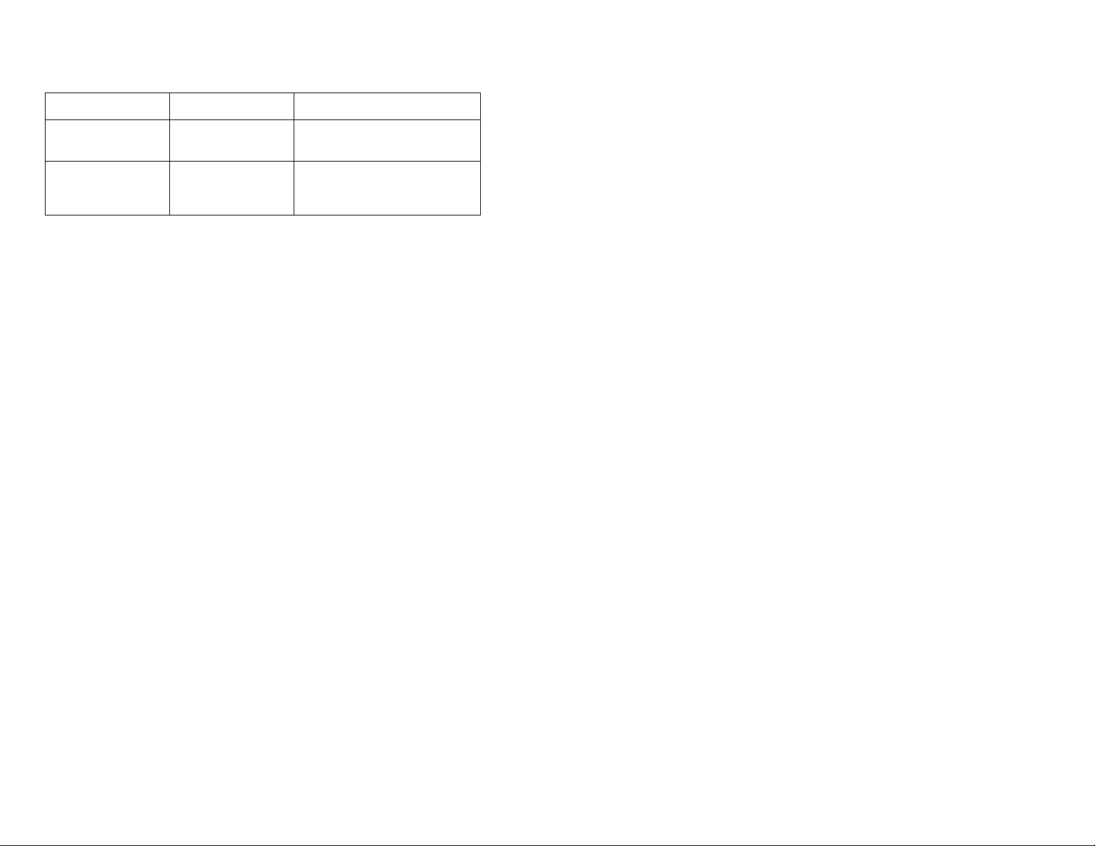
External speaker plug
The radio may be tuned to a duplex
Radio transmits on low
Link Tech’ equipment is warranted to be free defects in workmanship and
In the event of malfunction due to a defect during the one year warranted
period, Link Tech at its option, will either repair or replace the equipment. Any
This equipment must be properly package and returned to Link Tech for
authorized service. Any transportation, the purchaser whenever incurred in
les receipt to establish date of purchase must
This limited warranty does not extend to equipment which has been improperly
installed, (including those units that have been damaged due to reverse
, operated, subjected to misuse or abuse, neglected, water damaged,
altered or modified. In addition, any equipment which has been used in
violation of operating instructions or which have had the serial number altered
vice under this limited warranty. LT Marine
Electronics will not be liable for any incidental or consequential damages
resulting from the equipment or any defect. The limited warranty is void if
nty gives you specific legal rights, and you may have other rights
which vary from state to state. Some states do not allow the exclusion or
limitation of incidental or consequential damages so the above exclusion or
does not fit into jack
Radio transmits but
does not receive.
Incorrect plug or
speaker.
Channel mode.
The external speaker jack will
accept only RCA phone plugs.
channel meant for
ship-to-shore radio telephone
Antenna. Have antenna checked or test the
power only.
radio on another antenna. If
problem persists, contact LT for
service.
9. ONE YEAR LIMITED WARRANTY
THIS WARRANTY IS TO THE ORIGINAL PURCHASER
materials for a period of one year from date of purchase.
approved repair will be made without charge to the owner for parts and labor.
connection with this warranty will pay removal or reinstallation charge.
A copy of the original sa
accompany all claims under this limited warranty.
polarity)
or removed will be ineligible for ser
service done at any unauthorized service station.
This warra
limitation may not apply to you.
10. EASY REFERENCE GUIDE
Page 14

14
Channel 16 – Emergency
of the U.S.
Comments: U.S. Coast Guard does not regularly monitor this channel. Establish
Use: Communicating navigational and weather warnings to other ship
Communicating with U.S. Coast Guard stations or other vessels during search and
Use: Broadcast of information concerning the environmental conditions in which
weather, sea conditions, time signals, notices to mariner, hazards to
of
Vessels: Those used primarily for commercial transport of persons or goods, or
ship) or between commercial
Your ship is sinking, or on fire
Someone has been lost overboard
There exists grave and imminent danger
Channel 22 – U.S. Coast Guard
Use: Working channel for exchange of communications with stations
Coast Guard
Between:
Ship to U.S. Coast Guard ship, coast to aircraft stations
contact on channel 16 and shift to channel 22 as directed.
Channel 6 – Inter ship Safety
rescue operations
Between:
Comments:
Ship- To-Ship Only
Do not use for routine communications. This is a safety channel
Channel 15 – Environmental
Vessels: any (receive only)
vessels operatenavigation
Between: One-way broadcast from coast to ship stations
Note: Currently used for Class C EPIRB emergency signals.
Channel 17 – State Control
Vessels: State and local government
Use: Coordination, regulation and control of boating activities and the rendering
assistance to vessels.
Between: Ship and coast stations associated with state and local governments.
Commercial
Channels: 7, 8, 9, 10, 11, 18, 19, 67, 79, 90, (88)
engaged in servicing other vessels
Use: Communications pertaining to the purpose for which the vessel is used
Between: Commercial transport vessels (ship- to-
transport vessels and limited coast stations
Channels 8, 67 and 88 may not be used for ship-to-coast communications
Recreational boats are not permitted to use these channels
Channel 88 not available on Great Lakes and St. Lawrence Seaway.
Non Commercial (Boat Operations)
.
Page 15

15
Channels: 9, 68, 69, 71, 72, 78
boats and any other not used primarily for commercial
Use: Communications pertaining to the needs of the vessel (i.e., fishing, rendezvous,
Comments: Channel 72 may not be used for ship to coast communications. Channel
If you regularly monitor one of these channels with a second receiver, please notify
Use: Messages relating to the operational handling, movement and safety of vessels
Comments: Channel 77 is limited to communications to and from commercial pilots
Note: Channels 11, 12, 13 and 14 are used for vessel traffic service on the Great
Use: To place a telephone call to any location in the world or to a vessel outside of
Comments: Contact the marine operator on the channel assigned to your navigating
Be patient. Do not interrupt calls in progress. Avoid excessive calling if the operator
Vessels: Recreational
transport.
maneuvers, berthing scheduling of repairs, provisioning, etc.)
Between: Ship- to-ship or ship to limited coast stations
9 is shared with commercial users.
frequently called stations of this practice. Help reduce congestion on channel 16.
Port Operations
Channels: 5, 12, 14, 20, 65, 66, 73, 74, (77)
Vessels: Any
in or near ports, locks and waterways
Between: Ship- to-ship or ship-to-coast
concerning the movement and docking of vessels.
Lakes, St. Lawrence Seaway and designated major ports.
Marine Operator
Channels: 24, 25, 26, 27, 28, 84, 85, 86, 87, 88
Vessels: Any
your transmitting range
Between: Vessels and public coast stations
area. If unable to determine this channel, use channel 16
does not answer – give the operator a chance to reply.
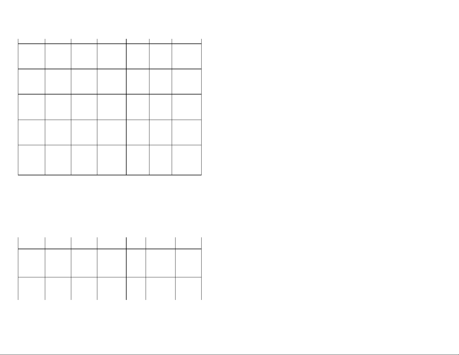
11. U.S.A., CANADIAN AND INTERNATION CHANNELS
COMPREHENSIVE LIST OF ALL CHANNELS AVAILABLE IN TRANSCEIVER
TX FREQ RX FREQ SIMPLEX/ DUPLEX
01 156.050 156.050 160.650 D D HI/LO
02 156.100 Intl Only 160.700 D HI/LO
03 156.150 Intl Only 160.750 D HI/LO
CHANNEL (MHz) USA
(MHz)
INTL
(MHz)
USA INTL
POWER
Page 16
16
04 156.200 Intl Only 160.800 D HI/LO
This page contains a comprehensive list of channels available in the transceiver for
ndicated. (USA and International use). You may use only
those channel authorized by the regulatory authorities in the waters of the country in
which you are operating. Also you may use only those channel authorized for your
The regulatory authorities can provide you with an updated list of channel which will
05 156.250 156.250 160.850 S D HI/LO
06 156.300 156.300 156.300 S HI/LO
07 156.350 156.350 160.950 S D HI/LO
08 156.400 156.400 156.400 S S HI/LO
09 156.450 156.450 156.450 S S HI/LO
10 156.500 156.500 156.500 S S HI/LO
11 156.550 156.550 156.550 S S HI/LO
12 156.600 156.600 156.600 S S HI/LO
13* 156.650 156.650 156.650 S S LO
14 156.700 156.700 156.700 S S HI/LO
15 156.750 156.750 156.750 S S LO
16 156.800 156.800 156.800 S S HI/LO
17 156.850 156.850 156.850 S S LO
18 156.900 154.900 161.500 S D HI/LO
19 156.950 156.950 161.550 S D HI/LO
20 157.000 157.000 161.000 S D HI/LO
21 157.050 157.050 161.650 S D HI/LO
22 157.100 157.100 161.700 S D HI/LO
23 157.150 157.150 161.750 S D HI/LO
24 157.200 161.800 161.800 D D HI/LO
25 157.250 161.850 161.850 D D HI/LO
26 157.300 161.900 161.900 HI/LO
27 157.350 161.950 161.950 D D HI/LO
28 157.400 162.000 161.950 D D HI/LO
37 157.850 Intl Only 157.850 S HI/LO
39 157.950 Intl Only 157.950 S HI/LO
transmit and receive as i
type of vessel or maritime service.
indicate the type of traffic, type of vessel, area authorized and type of use allowed.
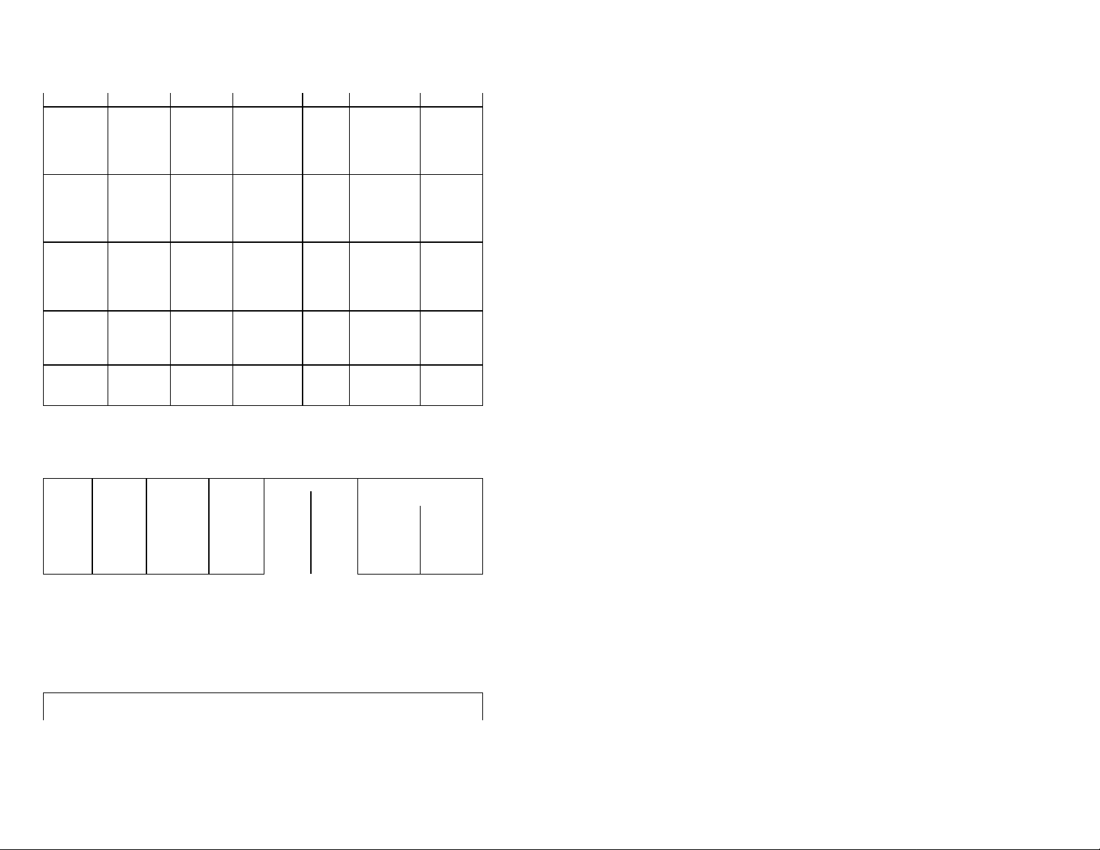
CHANNEL (MHz) USA
(MHz)
INTL
(MHz)
USA
INTL
60 156.025 156.025 160.625 S D HI/LO
61 156.075 Intl Only 160.675 D HI/LO
62 156.125 Intl Only 160.725 D HI/LO
63 156.175 156.175 160.775 S D HI/LO
64 156.225 156.225 160.825 S D HI/LO
65 156.275 156.275 160.875 S D HI/LO
66 156.325 156.325 160.925 S D HI/LO
67* 156.375 156.375 156.375 S S LO
68 156.425 156.425 156.425 S S HI/LO
POWER
Page 17
17
69 156.475 156.475 156.475 S S HI/LO
161.625
161.425
This page contains comprehensive list of channels available in the transceiver for
transmit and receive as indicated. (USA and International use). You may use only
ers of the country in which you are
operating. Also, you may use only those channels authorized for your type of vessel
The regulatory authorities can provide you with an updated list of channels, which will
70 156.525 156.525 156.525 S S HI/LO
71 156.575 156.575 156.575 S S HI/LO
72 156.625 156.625 156.625 S S HI/LO
73 156.675 156.675 156.675 S S HI/LO
74 156.725 156.725 156.725 S S HI/LO
75
76
77 156.875 156.875 156.875 S S HI/LO
78 156.925 156.925 161.525 S D HI/LO
79 156.975 156.975 161.575 S D HI/LO
80 157.025 157.025 161.625 S D HI/LO
81 157.075 157.075 161.675 S D HI/LO
82 157.125 157.125 161.725 S D HI/LO
83 157.175 157.175 161.775 S D HI/LO
84 157.225 161.825 161.825 D D HI/LO
85 157.275 161.875 161.875 D D HI/LO
86 157.325 161.925 161.925 D D HI/LO
87 157.375 161.975 161.975 D D HI/LO
88 157.425 157.425 162.025 S D HI/LO
M0 157.850 Intl Only 157.850 S HI/LO
M1**
M2
*May be increased to 25 watts on PTT
*Not currently assigned for USA or International use.
Intl Only 157.025 D HI/LO
Intl Only 161.425 S HI/LO
WEATHER RECEIVER ONLY CHANNELS
TX RX FREQ TX RX FREQ
CH FREQ USA INTL CH FREQ USA INTL
00 - 163.275 163.275 05 - 162.450 162.450
01 - 162.550 162.550 06 - 162.500 162.500
02 - 162.400 162.400 07 - 162.525 162.525
03 - 162.475 162.475 08 - 161.650 161.650
04 - 162.425 162.425 09 - 161.775 161.775
those channels authorized by regulatory in the wat
or maritime service.
indicate the type of traffi c, type of vessel, area authorized and type of use allowed.
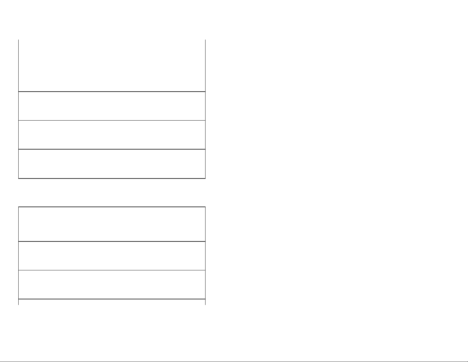
U.S.A. CHANNEL AUTHORIZATION
CH TX FREQ RX FREQ AUTHORIZED USE
01A 156.050 156.050 Public Correspondence, Port Operation
Page 18
18
05A 156.250 156.250 Public Correspondence, Port Operation
06 156.300 156.300 Safety (Compulsory)
07A 156.350 156.350 Commercial
08 156.400 156.400 Commercial, Internship
09 156.450 156.450 Commercial/Non- Commercial
10 156.500 156.500 Commercial
11 156.550 156.550 Commercial/VTS
12 156.600 156.600 Port Operations/VTS
13 156.650 156.650 Bridge to Bridge, (1W) Navigational
14 156.700 156.700 Port Operations/VTS
15 156.750 RX ONLY – Coast to ship
16 156.800 156.800 Calling and Safety (Compulsory)
17 156.850 156.850 State Controlled Ship to Coast (1W)
18A 156.900 156.900 Commercial
19A 156.950 156.950 Port Operation
20 157.000 157.000 Port Operation
21A 157.050 157.050 U.S. Government Only
22A 157.100 157.100 USCG ONLY
23A 157.150 157.150 Port Operation (U.S. Govt. Only)
24 157.200 161.800 Public Correspondence
25 157.250 161.850 Public Correspondence
26 157.300 161.900 Public Correspondence
27 157.350 161.950 Public Correspondence
28 157.400 162.000 Public Correspondence
Please Note: Channels 13 and 67 are limited to 1 watt except as overridden
(When necessary and allowable) by PTT.
Channel 70 reserved for digital selective calling
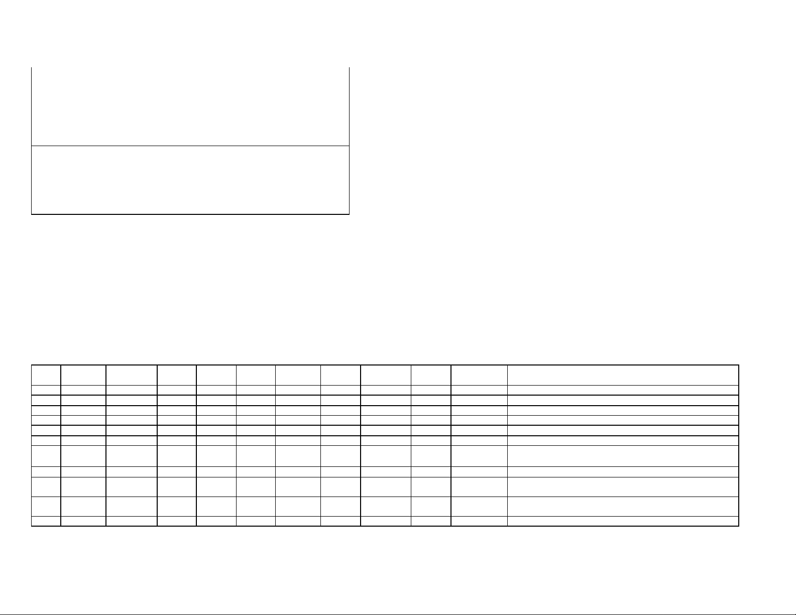
U.S.A. CHANNEL AUTHORIZATION
CH TX FREQ RX FREQ AUTHORIZED USE
63a 156.175 156.175 Public Correspondence, Port Operation
64 156.225 Public Correspondence, Port Operation
65A 156.275 156.275 Port Operation, VTS
66A 156.325 156.325 Port Operation, VTS
67 156.375 156.375 Commercial, VTS (1W)
68 156.425 156.425 Non-Commercial
69 156.475 156.475 Non-Commercial
70 156.525 156.525 Non-Commercial
71 156.575 156.575 Inter- Ship, Port Operation, Non-Commercial
72 156.625 156.625 Non-Commercial
73 156.675 156.675 Port Operation, VTS
74 1156.725 156.725 Port Operation, VTS
77 156.875 156.875 Inter-Ship, Port Operation
78A 156.925 156.925 Non-Commercial
79A 156.975 156.975 Commercial
80A 157.025 157.025 Commercial
Page 19
19
81A 157.075 157.075 U.S. Government Only
82A 157.125 157.125 U.S. Government Only
83A 157.175 157.175 U.S. Government Only
84 157.225 161.825 Public Correspondence
85 157.275 161.875 Public Correspondence
86 157.325 161.925 Public Correspondence
87 157.375 161.975 Public Correspondence
88 157.425 157.425 Commercial, Aircraft
WX02 162.400 Weather (RX Only)
WX03 162.475 Weather (RX Only)
WX04 162.425 Weather (RX Only)
WX06 162.500 Weather (RX Only)
WX07 162.525 Weather (RX Only)
WX08 161.650 Weather (RX Only)
WX09 161.775 Weather (RX Only)
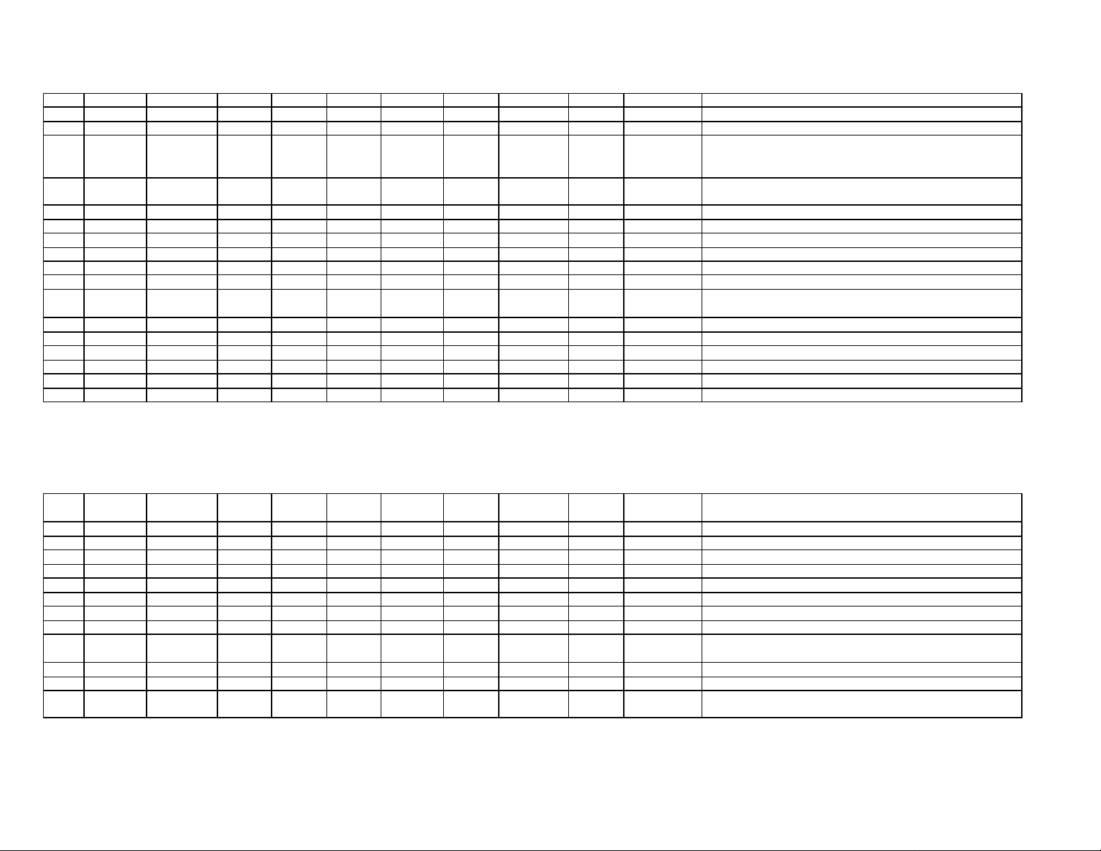
CANNDIAN CHANNEL AUTHORIZATION
CH TX RX Inter
Ship
1 156.050 160.650 X PC
2 156.100 160.700 X PC
3 156.150 160.750 X PC
4A 156.200 156.200 X X X PC Canadian coast guard search and rescue
4A 156.200 156.200 X X X EC Commercial fishing only.
5A 156.250 X
6 156.300 N/A X X X X All areas May by used for search and rescue between ships and air.
7A 156.350 156.350 X X X All areas
8 156.40 N/A X X X WC,EC Also assigned for op in Lake Winnipeg area.
9 156.450 156.450 X X X X X AC Used to communicate w/aircraft and helicopters
10 156.500 156.500 X X X X X X AC,GL Used also for communications w/aircraft engaged in
11 156.550 156.550 X X X X X PC,AC,GL Also used for pilot age purposes.
Ship
Shore
Comm -
ercial
Non-
Comm
Safety Ship
Movement
Public
Corres
Area of OP. Notes and Remarks
predominantly maritime support operations.
coordinated search & rescue and antipollution op.
Page 20
20
12 156.600 156.00 X X X X X WC,AC,GL Port operations & pilot in for and messages.
13 156.650 156.650 X X X X All areas Exclusively for bridge -to-bridge navigational traffic.
14 156.700 156.700 X X X X X AC,GL Port operations and pilot info and messages.
15 156.750 156.750 X X X X X All areas All operations limited to1-watt max power. May also be used
for on-board communications.
16 156.800 156.800 All areas INTERATIONAL DISTRESS, SAFETY 7 CALLING
17 156.850 156.850 X X X X X All areas All operations limited to 1-watt max power. May also be used
for on-board communications.
18A 156.900 156.900 X X X All areas Towing on the Pacific Coast.
19A 156.950 156.950 X X All areas Not in PC/Canadian Coast Guard Only.
19A 156.950 156.950 X X PC Various Government departments.
20 157.000 161.600 X X X All areas Port operations only with 1-watt max power.
21A 157.050 157.050 X X All areas Canadian Coast Guard Only.
21B N/A 161.650 X All areas Continuous Marine Broadcast (CMB) service.
22A 157.100 157.100 X X X X All areas For communication between Canadian Coast Guard and
non -Canadian Coast Guard stations only.
23 157.150 161.750 X X PC Also inland waters of British Columbia & Yukon.
24 157.200 161.800 X X All areas
25 157.250 161.850 X X PC Also assigned op in Lake Winnipeg area.
25B N/A 161.850 X AC Continuous Marine Broadcast (CMB) service.
26 157.300 161.900 X X X All areas
27 157.350 161.950 X X AC,GL,PC
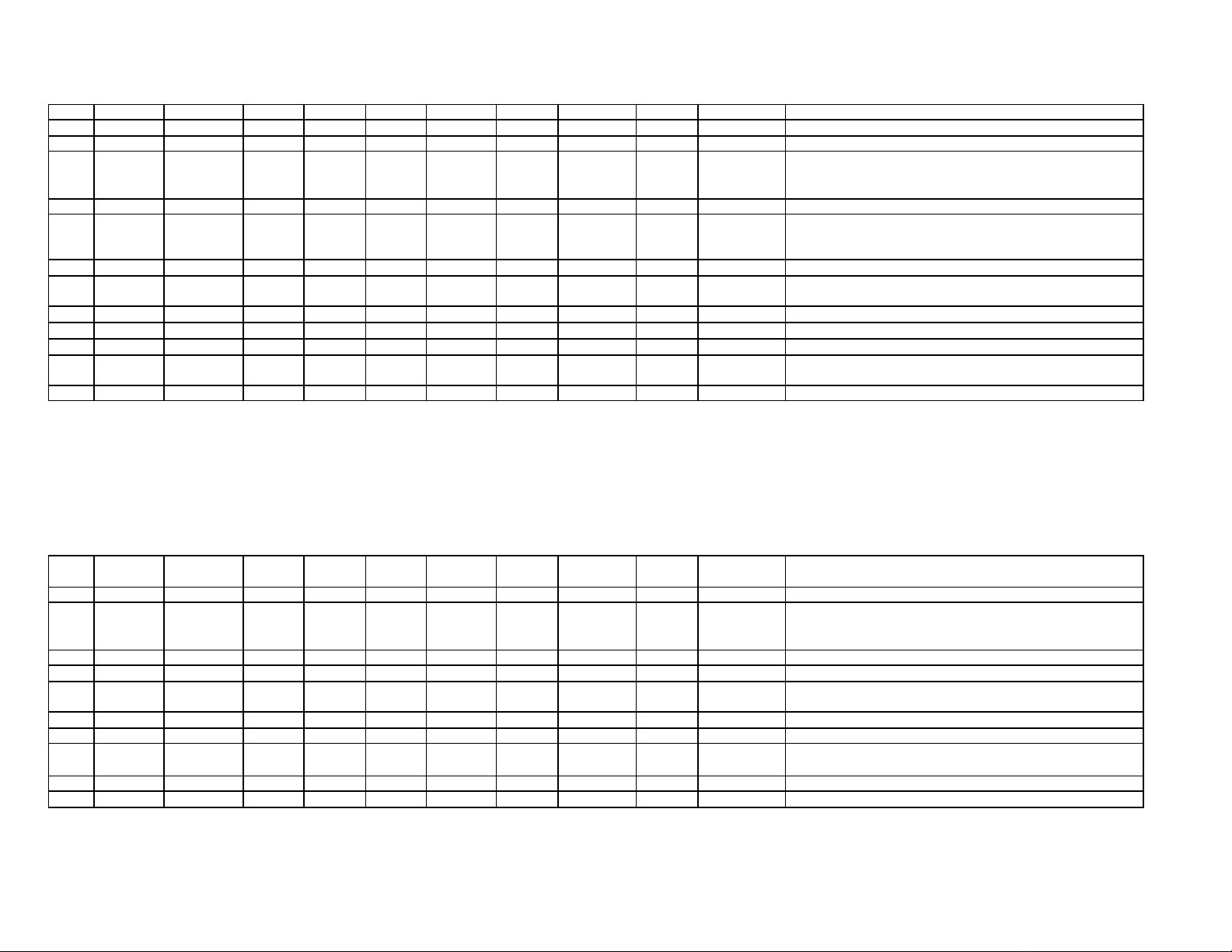
CANADIAN CHANNEL AUTORIZATION (Continued)
CH TX RX Inter-
Ship
Ship/
Shore
Comm -
ercial
Non-
Comm
Safety Ship
Movement
Public
Corres
Area of OP. Notes Remarks
28 157.400 162.000 X X X PC
28B N/A 162.000 AC Continuos Marine Broadcast (CNB) Service.
60 156.025 160.625 X X PC
61A 156.075 156.075 X X PC Canadian Coast Guard Only.
61A 156.075 156.075 X X X EC Commercial fishing only.
62A 156.125 156.125 X X PC Canadian Coast Guard Only.
64 156.225 160.825 X X PC
64A 156.225 156.225 X X X X EC Commercial fishing only.
65A 156.275 156.275 X X X X X Search & rescue & antipollution ops. On the Great Lakes.
Towing on the Pacific Coast. Port op. Only in St. Lawrence.
66A 156.325 156.325 X X X X X X Port op only in the St. Lawrence River with 1-watt max.
67 156.375 156.375 X X X EC Commercial fishing only.
67 156.375 156.375 X X X X X All areas Not EC, also for comm. with air engaged in search & rescue
and antipollution operations.
Page 21
21
68 156.425 156.425 X X X All areas For marine and yacht clubs.
Marine & yacht clubs on East Coast & Lake Winnipeg. Use for
Canadian Coast Guard use only in St. Lawrence River/Great
69 156.475 156.475 X X X X All Areas Not EC.
69 156.475 156.475 X X X EC Commercial fishing only.
70 156.525 156.525 DIGITAL SELECTIVE CALLING FOR DISTRESS, SAFETY,
71 156.575 156.575 X X X X X X
71 156.575 156.575 X X X
72 156.625 N/A X X X EC,PC
73 156.675 156.675 X X X EC Commercial fishing only.
73 156.675 156.675 X X X X X All areas Not EC. Also used for comm. With aircraft engaged in
74 156.725 156.725 X X X X X EC,PC
75 Not available-guard band for Channel 16
76 Not available-guard band for Channel 16
77 156.875 156.875 X X X X Pilot age on Pacific Coast Port op only in St. Lawrence
78A 156.925 156.925 X X X EC,PC
CANADIAN CHANNEL AUTORIZATION (Continued)
CH TX RX Inter-
Ship
Ship/
Shore
79A 156.975 156.975 X X X EC,PC
80A 157.025 157.025 X X X EC,PC
81A 157.075 157.075 X X Canadian Coast Guard use only in St. Lawrence River/Great
81A 157.075 157.075 X X X PC Canadian Coast Guard antipollution.
82A 157.125 157.125 X X X PC Canadian Coast Guard use only.
82A 157.125 157.125 X X
83 157.175 161.775 X X PC Canadian Coast Guard use only.
83A 157.175 157.175 X X EC Canadian Coast Guard & other Governmental agencies.
83B N/A 161.775 X AC,GL Continuous Marine Broadcast (CMB) Service.
84 157.225 161.825 X X PC
85 157.275 161.875 X X AC,GL,NL
86 157.325 161.925 X X PC
Comm -
ercial
Non-
Comm
Safety Ship
Movement
Public
Corres
AND CALLING.
comm. w/aircraft and helicopters in predominantly maritime
support operations.
coordinated search & rescue and antipollution op.
River/Great Lake areas with 1-watt maximum power.
Area of OP. Notes Remarks
Lakes areas.
Lakes areas.
Page 22
22
87 157.375 161.975 X X AC,GL,NL
88 157.425 162.025 X X AC,GL,NL
WX1 N/A 162.550 X EC,PC Continuous Marine Broadcast (CMB) Service.
WX2 N/A X EC,PC Continuous Marine Broadcast (CMB) Service.
WX3 X EC,PC Continuous Marine Broadcast (CMB) Service.
EC (East Coast) Includes: NL, AC, GL and Eastern Arctic Areas
NL: New foundland and Labrador
AC: Atlantic Coast, Gulf and St. Lawrence River up to and including Montreal
GL: Great Lakes (including St. Lawrence above Montreal)
WC (West Coast): Pacific Coast, Western Arctic and Athabasca-Mackenzie Watershed areas
PC: Pacific Coast
All areas: Includes East and West Coast areas
 Loading...