

Page 1
2. The first tab across the top of the screen, labeled Install, should now be high-
Network PC Card
Instant Wireless
TM
Series
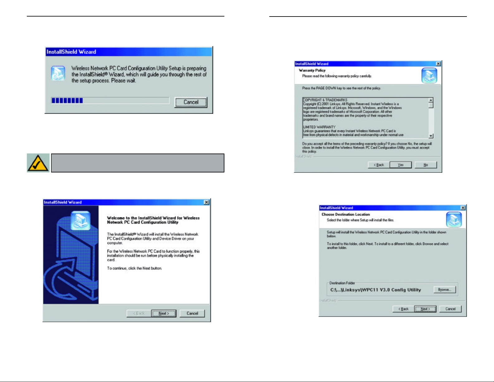
lighted. Click the Install button. A screen similar to that shown in Figure
2-2 should appear, indicating that Windows is preparing the installation.
Figure 2-2
If, for whatever reason, you need to abort or terminate the installation, press
the Cancel button at any time during the installation. Otherwise the installation will continue automatically.
Note: If you stop the installation before it has finished, you will have to
run the installation completely again before installing your hardware.
4. Figure 2-4 shows the Warranty Policy screen. Read the entire policy by
pressing the Page Down button on your keyboard or by using the on-screen
scroll bar. Click on the Yes button if you agree, or No if you disagree.
Clicking Nowill terminate the installation. If you click Yes, the installation
will continue.
3. The screen in Figure 2-3 will appear next, indicating that Windows is ready
to continue the installation. Click the Next button.
Figure 2-3
Figure 2-4
5. The screen in Figure 2-5 will appear next, requesting the folder into which
the Configuration Utility will be installed. To install the Configuration
Utility in the
default directory (recommended), click
the Next but-
ton. If you
prefer to install
the Utility in
another directory, click the
Browse button,
and locate the
preferred
directory.
Then, click the
Next button.
Figure 2-5
65
Page 2
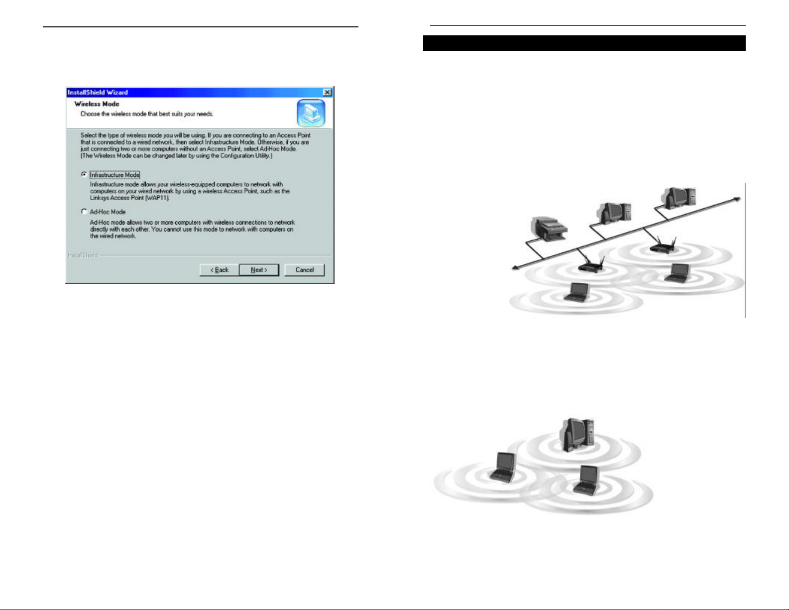
6. When the screen shown in Figure 2-6 appears, choose either Infrastructure
Network PC Card
Instant Wireless
TM
Series
mode or Ad-Hoc mode. If you are unsure whether to choose Infrastructure
or Ad-Hoc, refer to the next section for more information. Once you have
made your choice, click the Next button.
Figure 2-6
Ad-Hoc versus Infrastructure Mode
Unlike wired networks, wireless networks have two different modes in which
they may be set up: Infrastructure and Ad-Hoc. Choosing between these two
modes depends on whether or not the wireless network needs to share data or
peripherals with a wired network or not.
If the computers on the wireless network need to be accessible by a wired network or need to share a peripheral, such as a printer, with the wired network
computers, the wireless network should be set up in the Infrastructure mode.
The basis of Infrastructure mode centers around an access point, which serves
as the main point of communications in a wireless network (see Figure 2-7).
Access points transmit data to PCs equipped with wireless network cards,
which can roam
within a certain
radial range of the
access point.
Multiple access
points can be
arranged to work
in succession to
extend the roaming range, and can
be set up to communicate with
your Ethernet
hardware as well.
Figure 2-7
If the wireless network is relatively small and needs to share resources only
with the other computers on the wireless network, then the Ad-Hoc mode can
be used (shown in Figure 2-8). Ad-Hoc mode allows computers equipped with
wireless Network PC Cards to communicate directly with each other, eliminating the need for an access point. The drawback of this mode is in the fact that,
in Ad-Hoc mode, wireless-equipped computers are not able to communicate
with computers on a
wired network. And,
of course, communication between the
wireless-equipped
computers is limited
by the distance and
interference directly
between them.
Figure 2-8
87
Page 3
Infrastructure Mode
Instant Wireless
TM
Series
Network PC Card
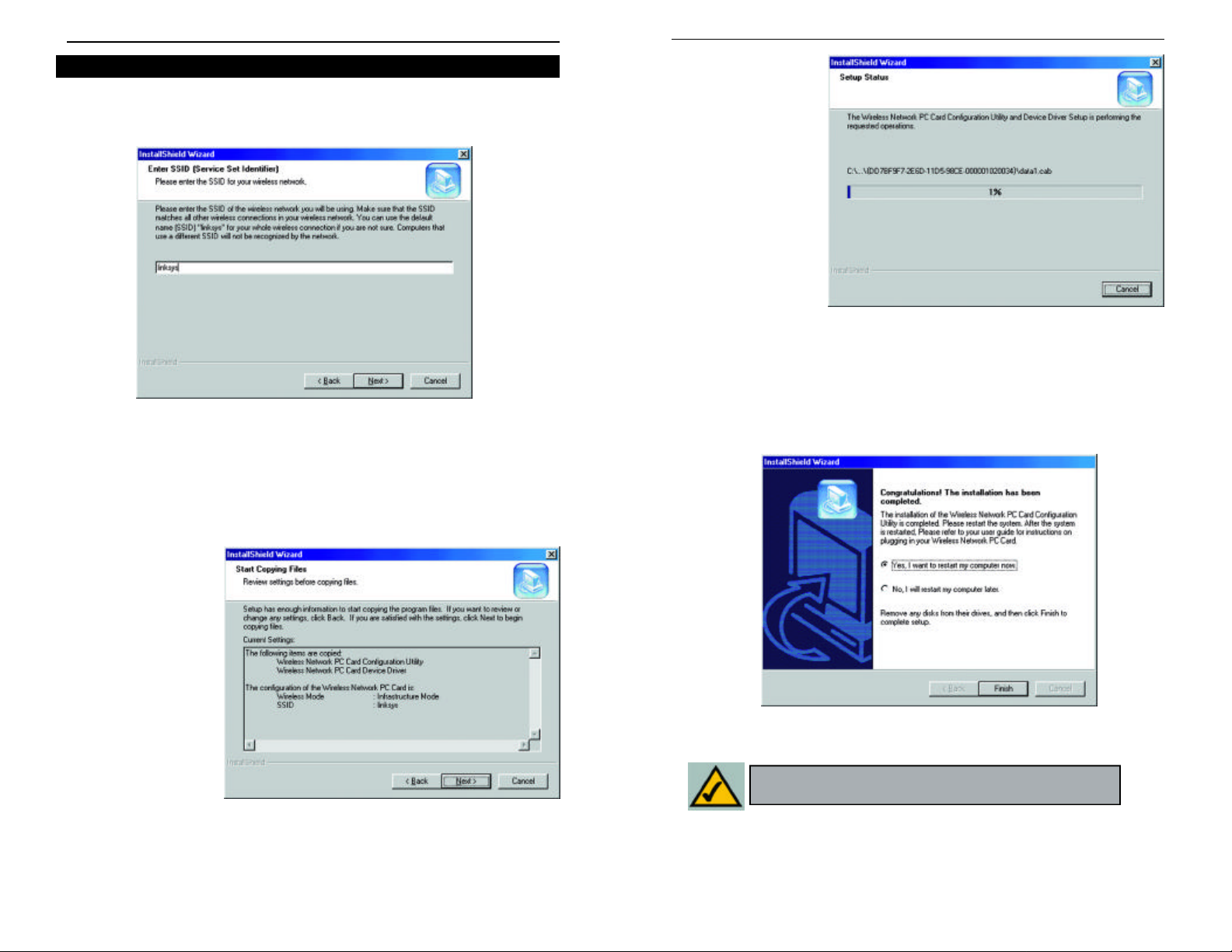
1. If you have chosen Infrastructure mode, the following screen (Figure 2-9)
will appear. If you have chosen Ad-Hoc mode, skip to the next section,
titled “Ad-Hoc Mode”.
Figure 2-9
You will be prompted to enter an SSID value in the box provided. The
SSID may be up to 32 characters in length. This may include any character
on the keyboard, keeping in mind that the SSID is case sensitive. All SSID
values on your wireless network must match. If you are unsure, use the
default value of “linksys.” Then, click the Next button.
3. The screen shown
in Figure 2-11 will
appear, indicating
that all of the
appropriate files
are being copied
onto your drive.
Click the Cancel
button if you need
to stop the installation for any reason.
Figure 2-11
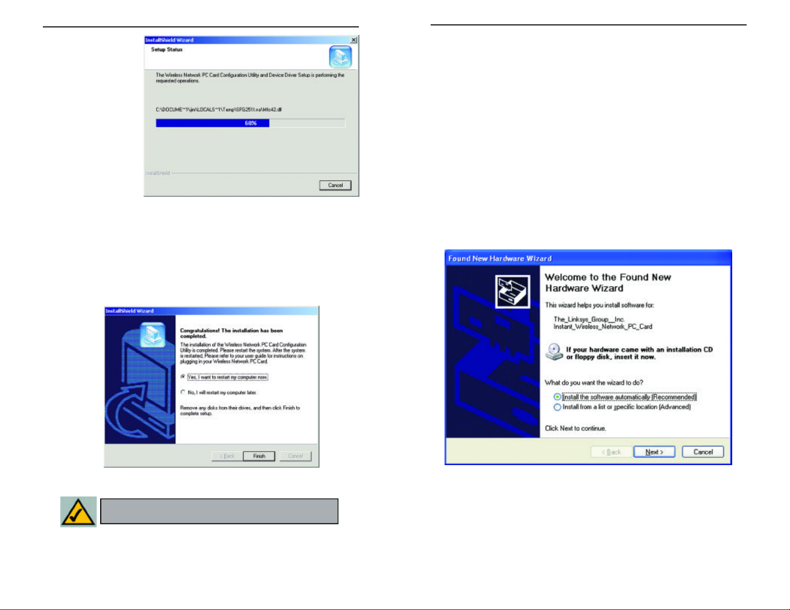
4. Once Windows has finished copying the necessary files, the screen shown
in Figure 2-12 will appear. In order for the drivers to be installed properly,
you must restart your computer. If you choose to do it now, select Yes, I
want to restart my computer now. If you do not want to do it now,
choose No, I will restart my computer later. Once you have made your
choice, click the Finish button to continue.
2. The Review
Settings screen
(Figure 2-10) will
appear next. Verify
that all the settings
are correct and
click the Next but-
ton to continue.
9
Figure 2-12
Note: Restart the computer and go to Chapter 3:
Installing the Network PC Card for further instructions.
Figure 2-10
10
Page 4
Network PC Card
Ad-Hoc Mode
Instant Wireless
TM
Series
1. If you have chosen Ad-Hoc mode, the following screen will appear. (See
Figure 2-13.) If you have chosen Infrastructure mode, refer to the previous section, titled “Infrastructure Mode”.
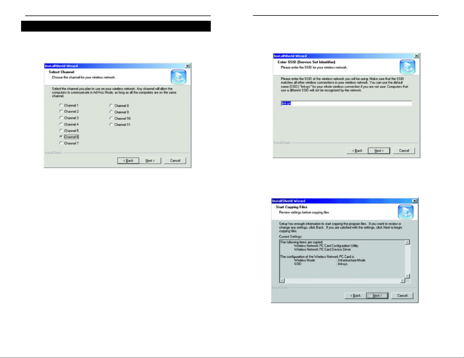
2. The screen shown in Figure 2-14 should appear. You will be prompted to
enter an SSID value in the field provided. All SSID values on your wireless network must match. If you are unsure, use the default value of
“linksys.” Then, click the Next button.
Figure 2-14
Figure 2-13
You will be prompted to choose a Channel from the list provided. All
computers on your wireless network must be using the same channel in
order to communicate with each other. If you are unsure about which channel to use, select the default channel (Channel 6). Once you have chosen
your channel, click the Next button.
11
3. The next screen to appear (Figure 2-15) will be the Review Settings screen.
Verify that all the settings are correct and click the Next button to continue.
Figure 2-15
12
Page 5
4. The next screen
Network PC Card
Instant Wireless
TM
Series
will indicate that all
of the appropriate
files are being
copied onto your
drive. (See Figure
2-16.) Click the
Cancel button if
you need to stop
the installation for
any reason.
Chapter 4: Installing the Drivers
and Configuration Utility for
Windows XP
Windows XP will automatically walk you through the driver installation
process as well as automatically configure the Network PC Card for your wireless network. If you have any questions regarding wireless networking on your
Windows XP PC, please refer to your Windows XP documentation.
Figure 2-16
5. Once Windows has finished copying the necessary files, a screen similar to
that shown in Figure 2-17 will appear. In order for the drivers to be
installed properly, you must restart your computer. If you choose to do it
now, select Yes, I want to restart my computer now. If you do not want
to do it now, choose No, I will restart my computer later. Once you have
made your choice, click the Finish button to continue.
Figure 2-17
To install the Network PC Card’s drivers, insert the Setup Utility CD-ROM into
your CD-Rom drive and then insert the card into your PC’s PCMCIA slot.
Windows XP will automatically detect the card and search for the appropriate
drivers. The screen in Figure 4-1 will then appear.
Figure 4-1
13
Note: Restart the computer and go to Chapter 5:
Installing the Network PC Card for further instructions.
Verify that the radio button beside Install the software automatically
(Recommended) is highlighted. If not, click it. Then, click the Next button to
continue.
14
Page 6
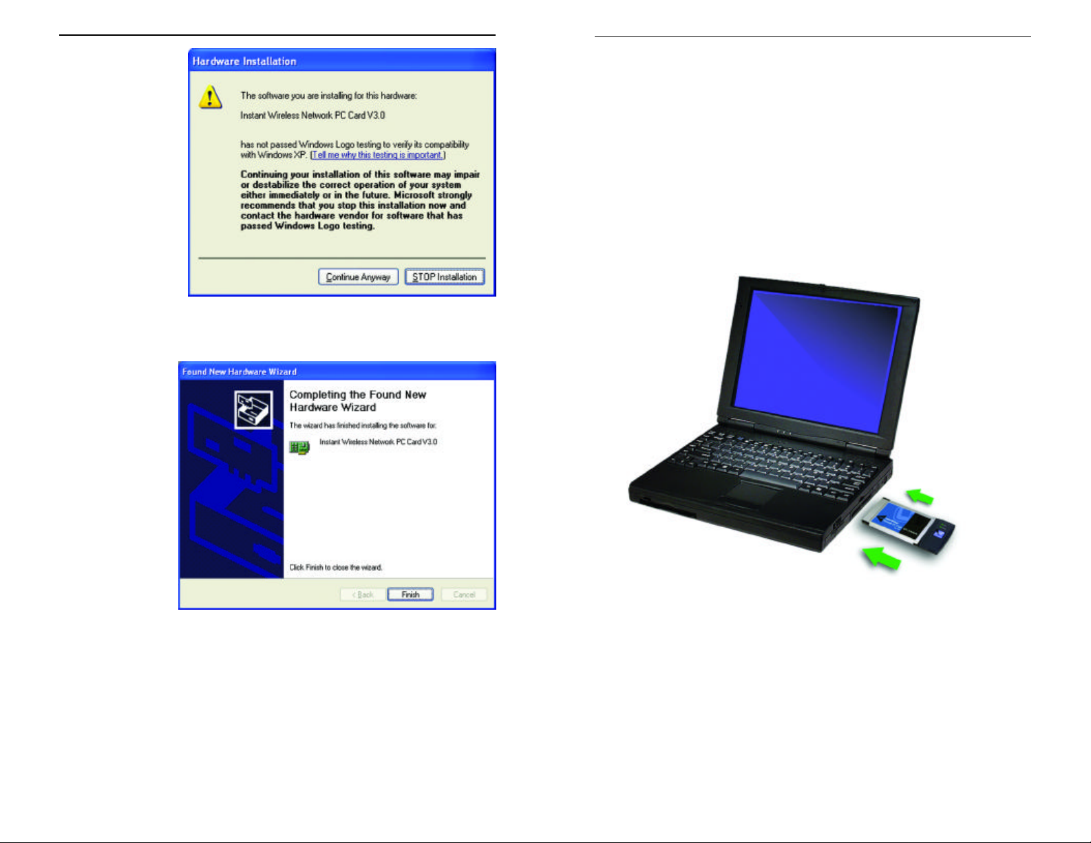
The Windows XP
Instant Wireless
TM
Series
Network PC Card
compatibility screen
will appear, as
shown in Figure 4-2.
As this card has
been tested to work
with Windows XP,
click the Continue
Anyway button to
continue.
On the final installation screen, click
the Finish button
to complete installation.
Chapter 5: Installing the Network
PC Card
1.Locate an available Type II or Type III PCMCIA slot on
your notebook computer.
2. With the Network PC Card’s 68-pin connector facing the PCMCIA slot
and the “Network PC Card” label facing up, as shown in Figure 5-1, slide the
Network PC Card completely into the PCMCIA slot while the computer is
restarting and before the Windows desktop appears.
Figure 4-2
Windows XP automatically detects and configures the Network PC Card for
your wireless network. To adjust these settings, refer to your Windows XP documentation.
15
Figure 4-3
The Hardware Installation is complete.
3. You may see several screens appear as the driver installation is finalized.
This is normal. No input should be necessary, and the screens should disappear when the card is ready for use.
The Hardware Installation is complete. Your Wireless Network PC Card
is set up and ready for use. You may continue reading to learn about the
card’s Configuration Utility in Chapter 6 for Windows NT or Chapter 7
for other Windows Operating Systems.
16
Page 7
Chapter 6: Installing the Drivers
Network PC Card
Instant Wireless
TM
Series
and Configuration Utility for
Installing the Drivers for Windows NT
Windows NT will set up the Network PC Card differently depending upon
whether you’ve previously installed network hardware or not. Please follow the
instructions appropriate for you.
Windows NT
Overview
The installation of the Network PC Card is different for users of Windows NT
because it is not a Plug-and-Play (PnP) operating system. This means it will not
automatically detect the presence of the Card when it is inserted.
Consequently, the order of the installation is different. The steps involved in
the installation are different, as well. If you are using any other operating sys-
tem than Windows NT, stop here and refer to the chapters regarding those operating systems.
Installing the Network PC Card In Your Notebook PC
1. Locate an available Type II or Type III PCMCIA slot on your notebook
computer.
2. With the Network PC Card’s 68-pin connector facing the PCMCIA slot
and the “Network PC Card” label facing up, slide the Network PC Card
completely into the PCMCIA slot while the computer is restarting and
before the Windows desktop appears.
The Hardware Installation is complete. Proceed to the next section for
driver installation.
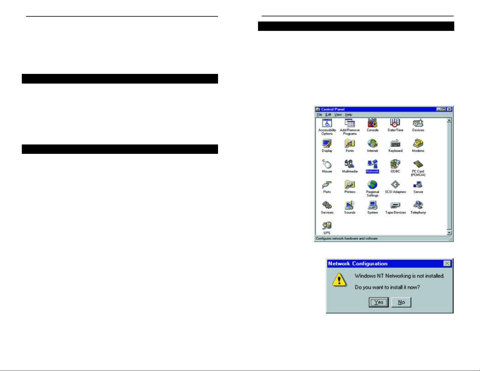
If You Have Never Installed Network Hardware:
1. Windows NT is not a Plug-and-Play Operating System and will not auto-
matically identify the Network PC Card. To begin setup, insert the Setup
Utility CD into your CD-ROM drive. If the Setup Utility CD attempts to
autorun, exit out of the utility to the desktop by clicking the Exit tab. Select
Settings from the
Start Menu and
bring up the
Control Panel
(as shown in
Figure 6-1).
Double-click the
Network icon.
17
Figure 6-1
2. Windows will display
the screen in Figure 62, showing that
Networking has not
been installed. Click
the Yes button to continue.
Figure 6-2
18
Page 8
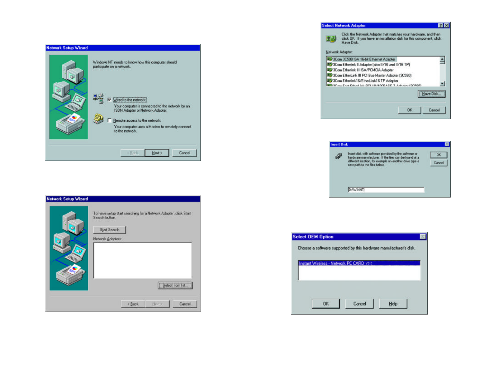
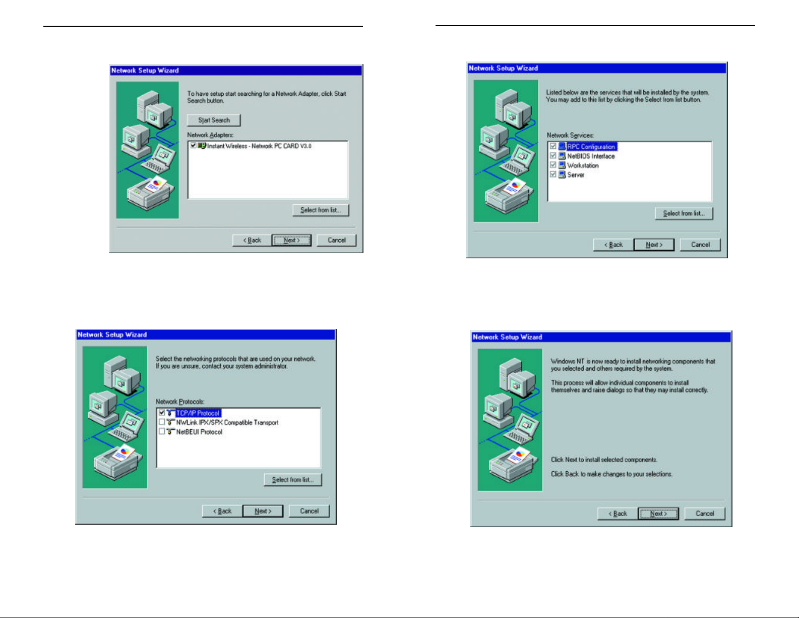
3. Installation will begin and you will reach the screen in Figure 6-3. You will
Network PC Card
Instant Wireless
Series
want to select the box that reads Wired to the network since you are adding
network hardware. Click the Next button to continue.
Figure 6-3
4. The screen shown in Figure 6-4 will not show any Network Adapters
installed on your system; this signifies that no network adapter has been previously installed. Click the Select from list button to continue.
5.A list of adapters
will appear as in
Figure 6-5. You will
not want to select
one of these, however, as your installation disk (the Setup
Utility CD) has all
of the appropriate
drivers. Click the
Have Disk button to
continue.
Figure 6-5
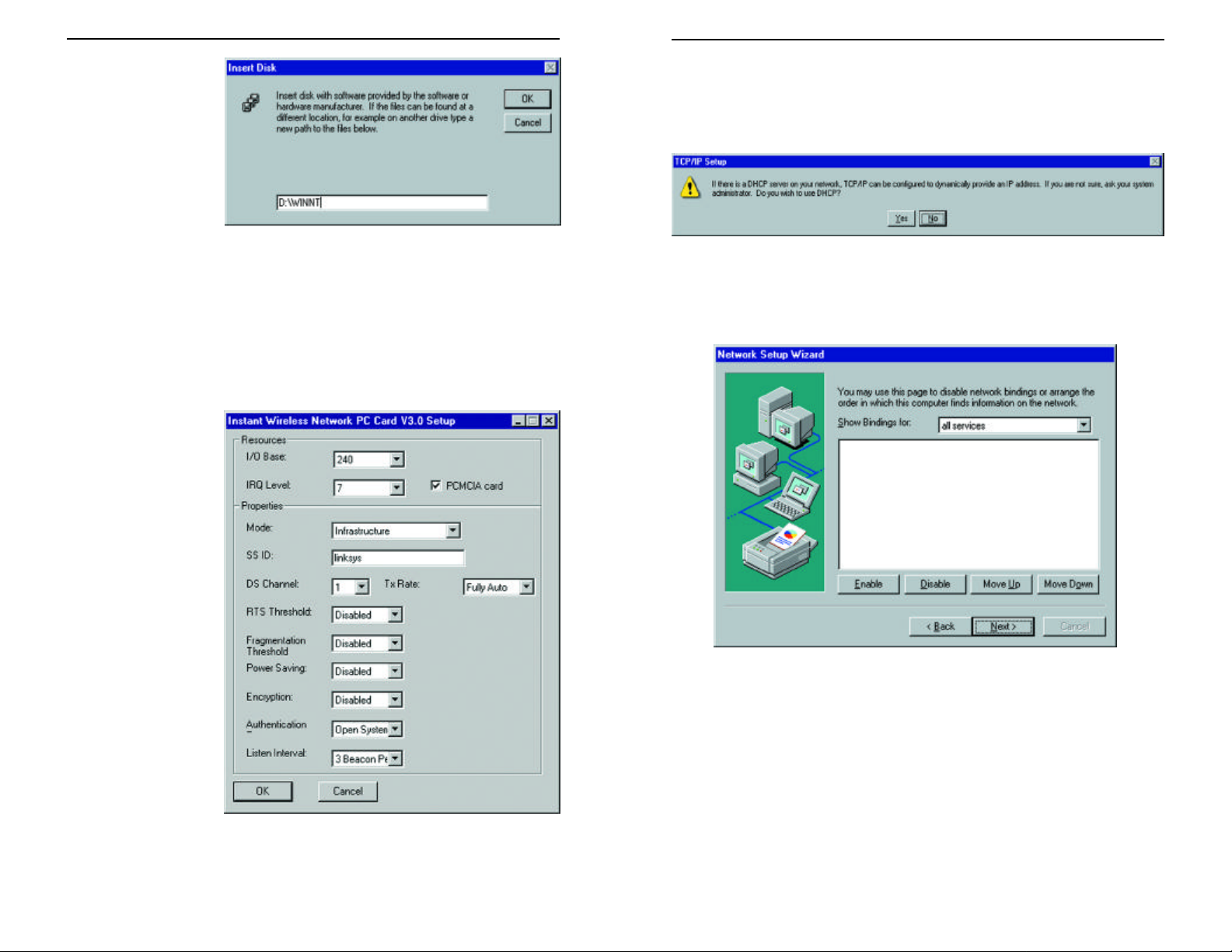
6. When the Insert Disk
screen appears (shown
in Figure 6-6), type
“D:\WINNT” in the
field provided and click
the OK button to continue.
19
Figure 6-4
Figure 6-6
7.The Select OEM Option screen (shown in Figure 6-7) will display all
available adapters. Make sure that Instant Wireless - Network PC Card
V3.0 is highlighted and click the OK button to continue.
Figure 6-7
20
Page 9
8. On the next screen, make sure there is a check mark in the box beside
Network PC Card
Instant Wireless
TM
Series
Instant Wireless - Network PC Card (as shown in Figure 6-8). Then click
the Next
button to
continue.
10. On the screen showing Network Services (Figure 6-10), the selections are
automatically made. Click the Next button to continue.
Figure 6-8
9.The next screen (Figure 6-9) will show the list of network protocols used on
your network. While the TCP/IP Protocolis already selected by default, you
should check with your network administrator before installing any additional network protocols. Click the Next button to continue.
Figure 6-9
Figure 6-10
11.As displayed in Figure 6-11, Windows NT will now be ready to start
installing networking components. After verifying your selections, click the
Next button to continue or click the Back button to make any necessary
corrections.
Figure 6-11
21
22
Page 10
12. Windows NT may
Network PC Card
Instant Wireless
Series
request further
files at this point
(as shown in
Figure 6-12). Type
“ D:\WINNT”
(where “D” represents your CDROM drive) in the
field provided and
click the Continue
Figure 6-12
button.
If files are still requested, insert your Windows NT CD into your CD-ROM
drive and type “D:\i386” (where “D” represents your CD-ROM drive).
Then, click the Continue button.
13.You will now reach the screen shown in Figure 6-13. This is called the
Resources & Properties screen. It is recommended that you leave these
options at their
default settings. If
settings must be
changed, it is preferred that you use
the Configuration
Utility that came
with the Network
PC Card. If you
must adjust the settings on this screen,
refer to Chapter 9:
Advanced
Properties for more
information on the
Advanced
Properties for
Windows NT. Click
the OK button to
continue.
14. After setting the Resource and Properties fields, Windows NT will begin
installing the network components you’ve selected. You may be presented
with the screen shown in Figure 6-14, asking if you would like to configure
the protocols with a DHCP server on your network. Click the Yes or No
button to continue. This setting may also be changed at a later time.
Figure 6-14
15. In the event that the screen shown in Figure 6-15 appears, do not make any
changes unless you are proficient with the advanced networking properties
of Windows NT. Click the Next button to continue.
Figure 6-15
16. At this point, Windows NT will let you know that it is ready to start the network. If you’d like to stop the procedure, click the Back button. To continue, click the Next button.
23 24
Figure 6-13
Page 11
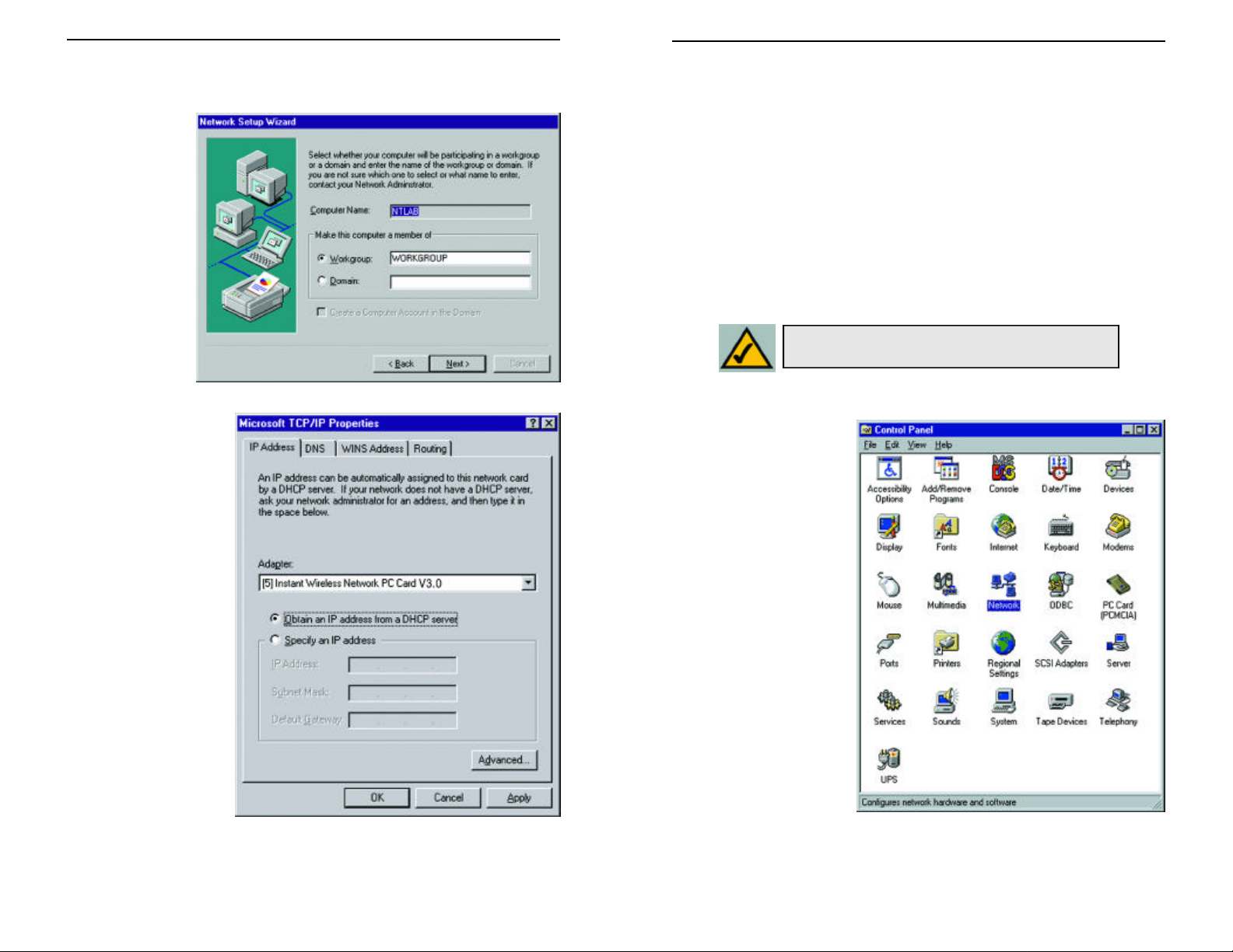
17. On the screen shown in Figure 6-15, enter your Computer Name, how your
Network PC Card
Instant Wireless
TM
Series
computer is identified on the network. Then, assign the computer to either
a Workgroup or Domain, whichever is appropriate. The Computer Name
must be different than any
other on the
Workgroup or
Domain. Click
the Next button.
Make sure that the Instant Wireless Network PC Card ver. 3.0 appears in the
Adapter window (as shown in Figure 6-17). Then, unless you need to
assign a static IP address, select Obtain an IP address from a DHCP
server and click the OK button. If you need to assign a static IP address,
select Specify an IP Address, and enter the appropriate values under IP
Address, Gateway Mask, and Default Gateway. After you have made your
choice, click the OK button.
Windows NT has now completed installing the network. Remove the Setup
Utility CD from the CD-ROM drive and click the Finish button to continue. Then, restart your computer.
The Driver Installation is complete. Continue now to the section called
Installing the Configuration Utility for Windows NT.
Note: After you have installed the Network PC
Card, reapply the Windows NT service pack.
18. Once the drivers
have been installed,
the following screen
(Figure 6-17) may
appear.
Figure 6-16
Figure 6-17
If You Have Installed Network Hardware Before:
1. Windows NT is not a
Plug-and-Play Operating
System and will not
automatically identify
the Network PC Card. To
begin setup, insert the
Setup Utility CD into
your CD-ROM drive and
then select Settingsfrom
the Start Menu. Bring
up the Control Panel (as
shown in Figure 6-18)
and double-click the
Network icon.
Figure 6-18
25 26
Page 12

2. To add the Network PC Card,
Network PC Card
Instant Wireless
TM
Series
click the Adapters tab (as
shown in Figure 6-19) and
5. The Select OEM Option screen will display all available adapters. Make
sure that Instant Wireless - Network PC Card V3.0 is highlighted, as
shown in Figure 6-22, and click the OK button to continue.
click the Add button to continue.
Figure 6-22
6. You will now reach the screen shown in Figure 6-13. This is called the
Figure 6-19
3. A list of adapters
will appear as
shown in Figure 6-
20. You will not
want to select one of
these, however, as
the Setup Utility
CD has all of the
appropriate drivers.
Click the Have Disk
button to continue.
Resources & Properties screen. It is recommended that you leave these
options at their
default settings. If
settings must be
changed, it is preferred that you use
the Configuration
Utility that came
with the Network PC
Card. If you must
adjust the settings on
this screen, refer to
Chapter 9: Advanced
Properties for more
information on the
Figure 6-20
Advanced Properties
for Windows NT.
4. On the Insert Disk
screen (Figure 6-21),
Click the OK button
to continue.
type “D:\WINNT” in
the field provided.
Then, click the OK
button to continue.
Figure 6-23
Figure 6-21
27 28
Page 13

7. The Network PC Card has
Network PC Card
Instant Wireless
TM
Series
now been installed. You will
see it added onto the screen
shown in Figure 6-24. Click
the Close button to continue
and then restart your computer.
Figure 6-24
If the screen shown in Figure 4-25 appears, make sure that the Instant Wireless
Network PC Card ver. 3.0 appears in the Adapter window. Then, unless you
need to assign a static IP address, select Obtain an IP address from a DHCP
server and click the OKbutton. If you need to assign a static IP address, select
Specify an IP Address, and enter the appropriate values under IP Address,
Gateway Mask, and Default Gateway . After you have made your choice,
click the OK button.
Windows NT has now completed installing the drivers. Remove the Setup
Utility CD from the CD-ROM drive and click the Finish button to continue.
Then, restart your computer.
NOTE: After you have installed the Network PC Card,
reapply the Windows NT service pack.
The Driver Installation is complete. Continue now to the section called
Installing the Configuration Utility for Windows NT.
Installing the Configuration Utility for Windows NT
8. Once the drivers have
been installed, the following screen (Figure
6-25) may appear.
Figure 6-25
29 30
Once you have restarted your computer, the drivers for the Card should load successfully. Now it is necessary to install the Configuration Utility. Insert the Setup
Utility CD in the CD-ROM drive. Unless you have deactivated the auto-run feature of Windows, the screen shown in Figure 6-26 should appear automatically.
Figure 6-26
Page 14

If this screen does not appear automatically, you can access the installation by
Network PC Card
Instant Wireless
TM
Series
clicking the Start button and choosing Run. In the drop-down box provided,
type D:\setup.exe (where D: is the letter of your CD-ROM drive). Alternately,
double-click My Computer, and then double-click the CD-ROM drive where
the Setup Utility CD is located. Double-click the Setup.exe icon that appears.
Follow the instructions that appear on your screen. If you have any questions
or difficulty, refer to the section called Installing the Drivers and
Configuration Utility for Windows 95, 98, ME, and 2000.
Chapter 7: Configuration Utility
The Configuration Utility is provided to allow you further customization of
the Network PC Card and your wireless network.
Using the Configuration Utility
Once the Configuration Utility has been installed, an icon will be placed in the
system tray (next to the clock) when the Network PC Card is inserted, as shown
in Figure 7-1.
Figure 7-1
You can also start the Configuration Utility by clicking the Startbutton, selecting Programs, and choosing the folder for the Network PC Card. Choose
Configuration Utility. You will see the Wireless LAN Configuration Utility
screen (shown in Figure 7-1). This utility is divided into six parts: Link Info,
Configuration, Site Survey, Encryption, Advanced, and About. You should
change all configuration settings for your Network PC Card using this utility
and not under the Network Properties section in your Control Panel.
31
LINK INFO
The Link Info screen (shown in Figure 7-2) provides information about the current link between the Network PC Card and a wireless Access Point.
When in Infrastructure Mode, State will display the connection statistics for
the network segment that you are on.
The Current Channel field shows to what channel the Network PC Card is set.
The Current Transfer Rate field shows the transfer rate in megabits per sec-
ond.
The Current Service Set Identifier shows the current SSID set for the wire-
less network. This SSID can be modified at the Configuration screen.
The Throughput fields show the rate at which data is transferred and received
in Bytes per second.
32
Page 15

Figure 7-2
Network PC Card
Instant Wireless
Series
CONFIGURATION
The Configuration screen, shown in Figure 7-3, allows you to customize the
settings for the Network PC Card and your wireless network.
The Wireless Mode setting determines the architecture of your wireless network. Select Ad-Hoc or Infrastructure Mode depending on your network
type. The Ad-Hoc mode is used for a simple peer-to-peer network and allows
the sharing of local resources only between Network PC Cards without need ing a wireless Access Point. The Infrastructure mode allows a wireless network to be integrated into an existed, wired network through an Access Point.
The Link Quality field will display a bar indicating the percentage, between 0
and 100 percent, of the quality of the link. The higher the percentage, the better the link.
The Signal Strength field will display a bar indicating the percentage, between
0 and 100 percent, of the strength of the signal. The higher the percentage, the
stronger the signal.
33
Note: When in Ad-Hoc mode, Link Quality and
Signal Strength indicators will not be available.
Figure 7-3
Infrastructure networks permit roaming between Access Points while maintaining a connection to all network resources.
An acronym for Service Set Identifier, SSID is the unique name shared among
all points in a wireless network. The SSID must be identical for all points in the
network. It is case sensitive and must not exceed 32 characters.
34
Page 16

The Transfer Rate field shows the current transfer rate for the Network PC
Network PC Card
Instant Wireless
TM
Series
Card. To optimize performance and range, the TX Rate should be set to Fully
Automatic, which will automatically adjust the transfer speed for best performance and longest range.
The Channel setting specifies the channel used in wireless communication and
should be set to the same channel as the other points in the wireless network.
This setting can only be adjusted in Ad-Hoc mode.
Power Saving Mode, or PS Mode, enables or disables the power saving features
of your Network PC Card.
SITE SURVEY
The Site Survey screen shows the available access points and their features.
Click on the desired access point. Then click Connect to connect or Search to
search for more access points.
ENCRYPTION
On the Encryption screen, shown in Figure 7-5, you can set the level of security
with which you will be using the Network PC Card.
Under the drop-down box, you can choose to have WEP encryption Disabled, 64-
Bit, or 128-Bit. Wired Equivalent Privacy (WEP) is an encryption scheme used to
protect wireless data communication. The Disabled setting prevents the sharing of
data with other computers on the WEP network. When selecting Manual Entry
for the WEP Key Entry, enter the hexadecimal number set by other wireless WEP
settings; these settings have to be identical to the WEP encryption on all points in
your wireless network in order to network to your Network PC Card.
35
Figure 7-4
Figure 7-5
Note: In order to enable WEP encryption,
hexadecimal values must be entered.
Note: The WEP Key Entry must match the Key on all other devices
on the wireless network, or else this device will be unable to transmit or receive data.
36
Page 17

In order to enable 128-bit WEP encryption, choose 128 Bits in the drop-down
Network PC Card
Instant Wireless
Series
box. In the drop-down box near the bottom right-hand corner of the page,
choose which Default Tx Key will be used for the encryption. By default, Key
1 will be used. In the box corresponding to the default you chose, enter a hexadecimal number that the encryption algorithm will be based on. Click Apply
Changes when you are done.
ADVANCED
The Advanced screen (Figure 7-6) allows you to set the Fragmentation
Threshold, the RTS/CTS Threshold, and the Preamble Type. The
Fragmentation Threshold Value indicates how much of the network resources
is devoted to recovering packet errors. The value should remain at its default
setting of 2,432. If you experience high packet error rates, you can decrease this
value but it will likely decrease overall network performance. Only minor modifications of this value are recommended.
The RTS Threshold Value should remain at its default setting of 2,432. A preamble is a signal used to synchronize the transmission timing between two or
more systems. A series of transmission pulses is sent before the data to indicate
that “someone is about transmit data.” This ensures that systems receiving the
information correctly when the data transmission starts.
Security is used for WEP only. By selecting Deny Unencrypted Data
Frames, all unencrypted data will not be seen. For Authentication Type, you
may choose between Open System or Shared Key .
Shared Key is when both the sender and recipient share a secret key. Both
units use this key for an extended length of time, sometimes indefinitely.
Any eavesdropper that discovers the key may decipher all packets until the
key is changed.
Open System, the default setting, is when the sender and the recipient do
not share a secret key. Each party generates its own key-pair and asks the
receiver to accept the (usually randomly) generated key. Once accepted,
this key is used for a short time only; then a new key is generated and
agreed upon.
The Preamble Type
should be set to Short (if
the network environment
is “noisy”) or Long (if the
environment is clear).
Click OK to complete the
configuration.
37
Figure 7-6
ABOUT
The About screen (Figure
7-7) shows the release
information for the Driver
Version, Configuration
Utility Version, and
Firmware Version
Figure 7-7
38
Page 18

Chapter 8: Installing Network
Network PC Card
Instant Wireless
Series
Protocols
Protocols are necessary for computers to communicate on your network.
3. Highlight Protocol from the
list of network component
types, as shown in Figure 8-3,
and click the Add button.
1. From the Start
Menu, select
Settings and
bring up the
Control Panel,
as shown in
Figure 8-1. From
the Control
Panel, doubleclick the
Network icon.
2. Select Instant Wireless
Network PC Card V3.0
from the list (as shown in
Figure 8-2) and click the
Add button.
Figure 8-1
4. From the screen
shown in Figure 84, select Microsoft
from the list of
“Manufacturers”
and TCP/IP from
the list of “Network
Protocols” and click
the OK button.
Repeat steps two
through four to
install other protocols, such as
NetBEUI or IPX/SPX.
5. To verify that the drivers are
working under Enhanced
Mode on the Driver Typetab
or reconfigure the card on
the Advanced tab, go to the
screen shown in Figure 8-2
and click the Properties but-
ton. This will bring up the
Properties Tabs, where such
values can be refined.
Figure 8-3
Figure 8-4
39
Figure 8-2
When finished, you must
restart your computer to
complete installation.
Figure 8-5
40
Page 19

Network PC Card
Chapter 9: Advanced Properties
Instant Wireless
TM
Series
The Advanced Properties for Windows 95, 98, ME, and 2000
The Advanced Properties of the card are supplied for fine tuning the card’s settings. These values should only be changed by those completely familiar with
both the operating system and the settings of the network. Unless your specific situation requires changing them, the default settings should be sufficient for
your card’s proper operation. Linksys advises that you change these values in
the Configuration Utility rather than using this method, to insure that the settings you change will be recognized everywhere.
Check your wireless network settings before changing any of these values.
1. To access the Network Configuration screen (shown in Figure 9-1), click the
Start button, choose Settings and open the Control Panel. Double-click the
Network icon and choose the Advanced tab.
2. Select Authentication
Algorithm from the list
provided and select a
Value from the dropdown menu on the
right, as shown in
Figure 9-2.
Figure 9-2
WECA Compliant (Default) (also referred to as Open Authentication)
The sender and recipient do NOT share a secret key. Each party generates its
own key-pair and asks the receiver to accept the generated key. Once accepted, this key is used for a short time only.
41 42
Figure 9-1
Must use Shared with WEP (Optional)
This is when both the sender and recipient share a secret key. They use this key
for an extended length of time. Any eavesdropper that discovers the key may
decipher all packets until the key is changed. As indicated, you should always
use WECA Compliant (Always Use) unless you have some other reason to do
so.
Choose Channel to continue or click the OK button to finish setting the
Advanced Options
Page 20

3. The Channel setting,
Network PC Card
Instant Wireless
TM
Series
shown in Figure 9-3,
must be the same for
all wireless points in
the network. Use the
settings, 1-11, to find
the best channel for
your connection. For
further information,
see Chapter 7:
Configuration
Utility. Once your
card is configured,
click the OKbutton to
finish setting the
Advanced Options.
4. Select either Disabled, 64
bit, or 128 bit as the
value under Encryption,
shown in Figure 9-4.
Wired Equivalent
Privacy (WEP) is an
encryption method used
to protect wireless data
communication. The
Disabled setting prevents the sharing of data
with other computers on
a WEP network. For data
sharing to be enabled,
select either 64 or 128 bit
encryption, depending
on your needs. For further information, see
Chapter 7:
Configuration Utility.
Once your card is configured, click OK to finish setting the Advanced
Options.
Figure 9-3
Figure 9-4
5. The Fragmentation
Threshold Value,
shown in Figure 9-5 indicates the maximum size
of the transmit frame.
Any data frame larger
than this value will be
fragmented into multiple
frames. Lowering this
value usually means a
lower frame error rate,
but a lower value also
creates more overhead,
which negatively affects
network performance.
The value can only be
entered in increments of
128. Only minor modifications of this value are
recommended. Click
Maximum Listen
Interval to continue or
the OK button to finish
setting the Advanced
Options.
6. The Maximum Listen
Interval, as shown in
Figure 9-6, only applies
when operating in the
Infrastructure mode
while Power Saving is
enabled. The value you
input here will determine how often the computer “wakes up” from
the power saving mode
to receive any packets
that were sent while it
was “asleep.” The higher
the value entered here,
the longer the time your
computer “sleeps”
between waking up to
check for packets. Click
Network Type to continue or the OK button
to finish setting the
Advanced Options.
Figure 9-5
Figure 9-6
43 44
Page 21

Network PC Card
7. Select Network Type
Instant Wireless
TM
Series
(Figure 9-7) and select a
Value, from the drop
down menu, of either
Infrastructure or AdHoc.
The Infrastructure mode
allows a Network PC
Card to communicate
with a wired network
employing an access
point, while the Ad-Hoc
mode allows wirelessto-wireless, peer-to-peer
communication. Click
Power Save Mode to
continue or the OK but-
ton to finish setting the
Advanced Options.
8. Select Power Save
Mode (shown in Figure
9-8) and select either
Enabled or Disabled
for the Value. Disabled
will allow for uninterrupted data communication. Selecting Enabled
allows your notebook to
enter “sleep” mode and
could interrupt data
communication. For
further information
about Power Save
Mode, see Chapter 7:
Configuration Utility.
Click Preamble Mode
to continue or the OK
button to finish setting
the Advanced Options.
Figure 9-7
Figure 9-8
9. A preamble is a signal
used to synchronize
the transmission timing between two or
more points in your
wireless network.
The default setting is
Long Tx Preamble
(as shown in Figure 9-
9). Long Tx Preamble
allows extra time for
the digital decoder to
process the initial
header packets, but is
transmitted at
11Mbps. Short Tx
Preamble allows for
less time to process
the packets, but initial
packets are transmitted at 2Mbps. Click
SSID to continue or
the OK button to finish setting the
Advanced Options.
10.RTS Threshold
should remain
Disabled the default
setting, as shown in
Figure 9-10. Do not
change the setting of
the RTS Threshold
unless connection
quality is poor. Then,
increase this setting by
a small value to establish a better connection. Click Network
Type to continue or
the OK button to finish setting the
Advanced Options.
Figure 9-9
Figure 9-10
45 46
Page 22

Network PC Card
11. The value for SSID
Instant Wireless
TM
Series
(Figure 9-11) depends
on what Network
Type was selected.
Infrastructure net-
works should have the
same SSID as the
Access Point. All
clients in an Ad-Hoc
Network should share
the same SSID. Click
Transmit Rate to
continue or the OK
button to finish setting the Advanced
Options.
12. The Transmit Rate
affects the speed of
transmission to another wireless device.
The rate can either be
set to a fixed value or
left at the default value
of Full Auto, as shown
in Figure 9-12, which
lets the computer
determine the best
transfer rate. The first
option, Auto Select 1
or 2, is for compatibility with older wireless
equipment. Click
WEP Passphrase to
continue or the OK
button to finish setting
the Advanced Options.
13.The WEP Passphrase (Figure 9-13) value allows the user to change the
passphrase that is used to generate the encryption key for WEP. Any
alphanumeric value can be entered here, but it will only be activated if you
choose either 64 or 128 bit under Encryption. This value can also be
changed using the Configuration Utility. For further information, see
Chapter 7: Configuration Utility.
Figure 9-11
Figure 9-13
Once your card is configured, click the OK button to finish setting the
Advanced Options.
Figure 9-12
47 48
Page 23

The Advanced Properties for Windows NT
Network PC Card
Instant Wireless
Series
The Advanced Properties screen allows you to make modifications to your
Network PC Card, optimizing performance. These properties are accessed by
right-clicking on the Network Neighborhood icon on the desktop. Select
Properties from the menu that appears. From the tabbed window that appears
next, click the Adapters tab. Highlight Instant Wireless Network PC Card
V3.0 and then click the Properties button. The screen in Figure 9-14 should
appear. Choosing improper settings in these fields can keep the Wireless
Network PC Card from functioning properly. Follow these steps to configure
the Advanced Properties fields:
1. The I/O Base setting,
shown in Figure 9-14,
should be unique and
not conflict with any
other device settings in
your system.
Figure 9-14
Note: In order to check for potential IRQ conflicts,
run WINMSD by selecting RUN from the Start menu
and typing winmsd.exe and pressing the Enter key.
2. The IRQ Base level
(Figure 9-15) can be
changed in order to
avoid possible conflicts
with other system
devices. The default
setting for the Network
PC Card is 7. This
value should only be
changed if the Card
does not work properly.
Figure 9-15
3. The Modesetting (Figure
9-16) should be either
Infrastructure or AdHoc, depending upon
your network’s settings.
The Infrastructure
mode allows
a Network PC Card to
communicate with a
wired network employing
an access point, while the
Ad-Hoc mode allows
wirelessto-wireless, peer-to-peer
communication. For
more information about
these settings, refer to the
section in Chapter 3
called Ad-Hoc versus
Infrastructure Mode.
Figure 9-16
49 50
Page 24

4. The SSID(as shown in
Network PC Card
Instant Wireless
TM
Series
Figure 9-17) depends
on what Mode is
selected. If the Mode
is Infrastructure , it
should have the same
SSID name as the
Access Point. If the
Mode is Ad-Hoc, all
clients should share
the same SSID name.
6. RTS Threshold should
remain in the default
setting of Disabled, as
shown in Figure 9-19.
Do not change the setting of the RTS
Threshold unless connection quality is poor.
Then, increase this setting by a small value to
establish a better connection.
Figure 9-17
Figure 9-19
5. The DS Channel set-
ting (Figure 9-18) must
be the same for all
wireless points in the
network. Use the settings, 1-11, to find the
best channel for your
connection.
7. Fragmentation
Threshold should
remain in the default
setting of Disabled,
as shown in Figure 9-
20. Do not change the
setting of the
Fragmentation
Threshold unless connection quality is
poor. Then, increase
this setting by a small
value to establish a
better connection.
Figure 9-18
51 52
Figure 9-20
Page 25

8. Under Power Saving
Network PC Card
Instant Wireless
TM
Series
mode (Figure 9-21),
select either Enabled
or Disabled. Disabled
will allow for uninterrupted data communication. Selecting
Enabled allows your
notebook to enter
“sleep” mode and
could interrupt data
communication. For
further information
about Power Save
Mode, see Chapter 7:
Configuration Utility.
10.The Authentication
setting, shown in Figure
9-23, is Open System
by default. Open
System is another name
for WECA compliant.
9. Select either Disabled,
64 bit, or 128 bit as
the value under
Encryption, as shown
in Figure 9-22). Wired
Figure 9-21
WECA Compliant (Default) (also referred to as Open Authentication)
The sender and recipient do NOT share a secret key. Each party generates
its own key-pair and asks the receiver to accept the generated key. Once
accepted, this key is used for a short time only; thereafter a new key is generated and agreed upon.
Figure 9-23
Equivalent Privacy
(WEP) is an encryption scheme used to
protect wireless data
communication. The
Disabled setting prevents the sharing of
Shared Key (Optional)
This is when both the sender and recipient share the same key. They use this
key for an extended length of time. Any eavesdropper that discovers the key
may decipher all packets until the key is changed. As indicated, you should
always use WECA Compliant (Always Use)unless you have some other rea-
son to do so.
data with other computers on a WEP network. For data sharing
Choose Listen Interval to continue or the OK button to finish setting the
Advanced Options
to be enabled, select
either 64 or 128 bit
encryption.
Figure 9-22
53 54
Page 26

Network PC Card
11.The Listen Interval
Instant Wireless
TM
Series
setting, as shown in
Figure 9-24, should
remain at 1 Beacon per
Second. Setting this
higher could result in
slower data transfer.
12.The TX Rate setting, as
shown in Figure 9-25,
should remain Fully
Auto as set by default.
Changing this to a different transfer rate will
lock in that rate and
may result in dropped
connections.
Click the OK button to
complete setting these
options.
Figure 9-24
Chapter 10: Troubleshooting
This chapter provides solutions to problems usually occurring during the instal-
lation and operation of the Network PC Card. Read the description below to
solve your problems. If you can’t find an answer here, check the Linksys web-
site at www.linksys.com.
Common Problems and Solutions
1.My computer does not recognize the Network PC Card.
Make sure that the Network PC Card is properly inserted into the PCMCIA
slot. Note that the card can be inserted either way, but only correctly when it
is inserted so that the “Instant Wireless” logo on the front of the card may not
be seen. If in doubt, try inserting the card both ways. The card will slide in
further when it is correct.
2.The Network PC Card does not work properly.
• Reinsert the Network PC Card into your notebook’s PCMCIA slot. A beep
should be heard if the card is properly inserted.
• For non-Windows environments, make sure that a PCMCIA card service
driver is installed on your PC.
• Open the Control Panel and click on the PC Card. Check whether it has a
PCMCIA card in one of the sockets or not. If you find the Network PC Card
in one of the sockets, it means the card has been detected properly. If you see
a yellow question mark, the resources are conflicting.
• Right-click on My Computer and select Properties. Select the device manager and click the Network Adapter. You will find the Network PC Card if
it is installed successfully. If you see the yellow exclamation mark, the
resources are conflicting. Click PCMCIA card and then click PCMCIA
card service. You will see the status of the Network PC Card. If there is a
yellow question mark, please check the following:
• Make sure your notebook has a free IRQ.
• Make sure you have inserted the right card and installed the proper
driver.
55
Figure 9-25
56
Page 27

If the Network PC Card does not function after attempting the above steps,
Network PC Card
Instant Wireless
TM
Series
remove the card and do the following:
• Uninstall the driver software from your PC.
• Restart your PC and repeat the hardware and software installation as
specified in this User Guide.
3.I cannot communicate with the other computers linked via Ethernet in
the Infrastructure configuration.
• Make sure that the notebook PC to which the Network PC Card is associated is powered on.
• Make sure that your Network PC Card is configured on the same channel and
with the same security options as the other computers in the Infrastructure
configuration.
Frequently Asked Questions
Can I run an application from a remote computer over the wireless network?
This will depend on whether or not the application is designed to be used over
a network. Consult the application’s documentation to determine if it supports
operation over a network.
Can I play multiplayer games with other users of the wireless network?
Yes, as long as the game supports multiple players over a LAN (local area network). Refer to the game’s documentation for more information.
What is the IEEE 802.11b standard?
The IEEE 802.11b Wireless LAN standards subcommittee formulatings standards for the industry. The objective is to enable wireless LAN hardware from
different manufacturers to communicate.
What IEEE 802.11 features are supported?
The product supports the following IEEE 802.11 functions:
• CSMA/CA plus Acknowledge protocol
• Multi-Channel Roaming
• Automatic Rate Selection
• RTS/CTS feature
• Fragmentation
• Power Management
What is Ad-hoc?
An Ad-hoc wireless LAN is a group of computers, each with a Network PC
Card, connected as an independent wireless LAN. An Ad-hoc wireless LAN is
applicable at a departmental scale for a branch or SOHO operation.
What is Infrastructure?
An integrated wireless and wired LAN is called an Infrastructure configuration. Infrastructure is applicable to enterprise scale for wireless access to a central database, or wireless application for mobile workers.
What is Roaming?
Roaming is the ability of a portable computer user to communicate continuously while moving freely throughout an area greater than that covered by a single Wireless Network Access Point.
To achieve true seamless connectivity, the wireless LAN must incorporate a
number of different functions. Each node and Wireless Network Access Point,
for example, must always acknowledge receipt of each message. Each node
must maintain contact with the wireless network even when not actually transmitting data. Achieving these functions simultaneously requires a dynamic RF
networking technology that links Wireless Network Access Points and nodes.
In such a system, the user’s end node undertakes a search for the best possible
access to the system. First, it evaluates such factors as signal strength and quality, as well as the message load currently being carried by each Wireless
Network Access Point and the distance of each Wireless Network Access Point
to the wired backbone. Based on that information, the node next selects the
right Wireless Network Access Point and registers its address. Communications
between end node and host computer can then be transmitted up and down the
backbone.
As the user moves on, the end node’s RF transmitter regularly checks the system to determine whether it is in touch with the original Wireless Network
Access Point or whether it should seek a new one. When a node no longer
receives acknowledgment from its original Wireless Network Access Point, it
undertakes a new search. Upon finding a new Wireless Network Access Point,
it then re-registers, and the communication process continues.
What is BSS ID?
A specific Ad-hoc LAN is called a Basic Service Set (BSS). Computers in a
BSS must be configured with the same BSS ID.
What is ESSID?
An Infrastructure configuration could also support roaming capability for
mobile workers. More than one BSS can be configured as an Extended Service
Set (ESS). Users within an ESS could roam freely between BSSs while maintaining a continuous connection to the wireless network stations and Wireless
Network Access Points.
57
58
Page 28

What is ISM band?
Network PC Card
Instant Wireless
TM
Series
The FCC and their counterparts outside of the U.S. have set aside bandwidth
for unlicensed use in the ISM (Industrial, Scientific and Medical) band.
Spectrum in the vicinity of 2.4 GHz, in particular, is being made available
worldwide. This presents a truly revolutionary opportunity to place convenient
high speed wireless capabilities in the hands of users around the globe.
What is Spread Spectrum?
Spread Spectrum technology is a wideband radio frequency technique developed by the military for use in reliable, secure, mission-critical communications systems. It is designed to trade off bandwidth efficiency for reliability,
integrity, and security. In other words, more bandwidth is consumed than in the
case of narrowband transmission, but the trade-off produces a signal that is, in
effect, louder and thus easier to detect, provided that the receiver knows the
parameters of the spread-spectrum signal being broadcast. If a receiver is not
tuned to the right frequency, a spread-spectrum signal looks like background
noise. There are two main alternatives, Direct Sequence Spread Spectrum
(DSSS) and Frequency Hopping Spread Spectrum (FHSS).
What is DSSS? What is FHSS? And what are their differences?
Frequency Hopping Spread Spectrum (FHSS) uses a narrowband carrier that
changes frequency in a pattern that is known to both transmitter and receiver.
Properly synchronized, the net effect is to maintain a single logical channel. To
an unintended receiver, FHSS appears to be short-duration impulse noise.
Direct Sequence Spread Spectrum (DSSS) generates a redundant bit pattern for
each bit to be transmitted. This bit pattern is called a chip (or chipping code).
The longer the chip, the greater the probability that the original data can be
recovered. Even if one or more bits in the chip are damaged during transmission, statistical techniques embedded in the radio can recover the original data
without the need for retransmission. To an unintended receiver, DSSS appears
as low power wideband noise and is rejected (ignored) by most narrowband
receivers.
Can Instant WirelessTMproducts support file and printer sharing?
Instant WirelessTMproducts perform the same function as LAN products.
Therefore, Instant WirelessTMproducts can work with Netware, Windows
NT/2000, or other LAN operating systems to support printer or file sharing.
What is WEP?
WEP is Wired Equivalent Privacy, a data privacy mechanism based on a 40 bit
shared key algorithm, as described in the IEEE 802.11 standard.
Would the information be intercepted while transmitting on air?
WLAN features two-fold protection in security. On the hardware side, as with
Direct Sequence Spread Spectrum technology, it has the inherent security feature of scrambling. On the software side, the WLAN series offers the encryption function (WEP) to enhance security and access control. Users can set it up
depending upon their needs.
59
60
Page 29

Network PC Card
Chapter 11: Glossary
Instant Wireless
TM
Series
Ad-hoc Network - An ad-hoc network is a wireless network or other small network in which some of the network devices are part of the network only for the
duration of a communications session while in some close proximity to the rest
of the network.
Architecture - The total design and implementation of the network. It includes
the network's topology, transmission technologies and communications protocols, management and security systems, and any other attributes that give a network a particular set of capabilities and functionalities.
Backbone - The part of a network that connects most of the systems and networks together and handles the most data.
Bandwidth - The transmission capacity of a given facility, in terms of how much
data the facility can transmit in a fixed amount of time; expressed in bits per second (bps).
Bit - A binary digit. The value - 0 or 1-used in the binary numbering system.
Also, the smallest form of data.
BSS (Basic Service Set) - A group of Instant Wireless Network PC Card users
and an Access Point.
Buffer - A buffer is a shared or assigned memory area used by hardware devices
or program processes that operate at different speeds or with different sets of priorities. The buffer allows each device or process to operate without being held up
by the other. In order for a buffer to be effective, the size of the buffer and the
algorithms for moving data into and out of the buffer need to be considered by
the buffer designer. Like a cache, a buffer is a "midpoint holding place" but exists
not so much to accelerate the speed of an activity as to support the coordination
of separate activities.
CSMA/CD (Carrier Sense Multiple Access/Collision Detection) - The LAN
access method used in Ethernet. When a device wants to gain access to the network, it checks to see if the network is quiet (senses the carrier). If it is not, it
waits a random amount of time before retrying. If the network is quiet and two
devices access the line at exactly the same time, their signals collide. When the
collision is detected, they both back off and each wait a random amount of time
before retrying.
Database - A database is a collection of data that is organized so that its contents
can easily be accessed, managed, and updated.
Default Gateway - The routing device used to forward all traffic that is not
addressed to a station within the local subnet.
DHCP (Dynamic Host Configuration Protocol) - A protocol that lets network
administrators manage centrally and automate the assignment of Internet
Protocol (IP) addresses in an organization's network. Using the Internet's set of
protocol (TCP/IP), each machine that can connect to the Internet needs a unique
IP address. When an organization sets up its computer users with a connection to
the Internet, an IP address must be assigned to each machine. Without DHCP, the
IP address must be entered manually at each computer and, if computers move to
another location in another part of the network, a new IP address must be entered.
DHCP lets a network administrator supervise and distribute IP addresses from a
central point and automatically sends a new IP address when a computer is
plugged into a different place in the network.
DHCP uses the concept of a "lease" or amount of time that a given IP address
will be valid for a computer. The lease time can vary depending on how long a
user is likely to require the Internet connection at a particular location. It's especially useful in education and other environments where users change frequently.
Using very short leases, DHCP can dynamically reconfigure networks in which
there are more computers than there are available IP addresses.
DHCP supports static addresses for computers containing Web servers that need
a permanent IP address.
Domain - A subnetwork comprised of a group of clients and servers under the
control of one security database. Dividing LANs into domains improves performance and security.
Driver - A workstation or server software module that provides an interface
between a network interface card and the upper-layer protocol software running
in the computer; it is designed for a specific NIC, and is installed during the initial installation of a network-compatible client or server operating system.
61
62
Page 30

Network PC Card
DSSS (Direct-Sequence Spread- Spectrum) - DSSS generates a redundant bit pat-
Instant Wireless
Series
tern for each bit to be transmitted. This bit pattern is called a chip (or chipping
code). The longer the chip, the greater the probability that the original data can
be recovered. Even if one or more bits in the chip are damaged during transmission, statistical techniques embedded in the radio can recover the original data
without -the need for retransmission. To an unintended receiver, DSSS appears as
low power wideband noise and is rejected (ignored) by most narrowband
receivers.
Encryption - A security method that applies a specific algorithm to data in order
to alter the data's appearance and prevent other devices from reading the information.
Hop - The link between two network nodes.
IEEE (The Institute of Electrical and Electronics Engineers) - The IEEE
describes itself as "the world's largest technical professional society, promoting
the development and application of electrotechnology and allied sciences for the
benefit of humanity, the advancement of the profession, and the well-being of our
members."
The IEEE fosters the development of standards that often become national and
international standards. The organization publishes a number of journals, has
many local chapters, and several large societies in special areas, such as the IEEE
Computer Society.
ESS - More than one BSS in a network.
Ethernet - IEEE standard network protocol that specifies how data is placed on
and retrieved from a common transmission medium. Has a transfer rate of 10
Mbps. Forms the underlying transport vehicle used by several upper-level protocols, including TCP/IP and XNS.
FHSS (Frequency Hopping Spread Spectrum) - FHSS continuously changes the
center frequency of a conventional carrier several times per second according to
a pseudo-random set of channels, while chirp spread spectrum changes the carrier frequency. Because a fixed frequency is not used, illegal monitoring of spread
spectrum signals is extremely difficult, if not downright impossible depending on
the particular method.
Firmware - Programming that is inserted into programmable read-only memory
(programmable read-only memory), thus becoming a permanent part of a computing device.
Fragmentation - Breaking a packet into smaller units when transmitting over a
network medium that cannot support the original size of the packet.
Gateway - A device that interconnects networks with different, incompatible
communications protocols.
Hardware - Hardware is the physical aspect of computers, telecommunications,
and other information technology devices. The term arose as a way to distinguish
the "box" and the electronic circuitry and components of a computer from the
program you put in it to make it do things. The program came to be known as the
software.
Infrastructure - An infrastructure network is a wireless network or other small
network in which the wireless network devices are made a part of the network
through the Access Point which connects them to the rest of the network.
IP Address - In the most widely installed level of the Internet Protocol (Internet
Protocol) today, an IP address is a 32-binary digit number that identifies each
sender or receiver of information that is sent in packet across the Internet. When
you request an HTML page or send e-mail, the Internet Protocol part of TCP/IP
includes your IP address in the message (actually, in each of the packets if more
than one is required) and sends it to the IP address that is obtained by looking up
the domain name in the Uniform Resource Locator you requested or in the e-mail
address you're sending a note to. At the other end, the recipient can see the IP
address of the Web page requestor or the e-mail sender and can respond by sending another message using the IP address it received.
IPX (Internetwork Packet EXchange) - A NetWare communications protocol
used to route messages from one node to another. IPX packets include network
addresses and can be routed from one network to another.
IRQ (Interrupt ReQuest) - A hardware interrupt on a PC. There are 16 IRQ lines
used to signal the CPU that a peripheral event has started or terminated. In most
cases, two devices cannot use the same line.
ISM band - The FCC and their counterparts outside of the U.S. have set aside
bandwidth for unlicensed use in the ISM (Industrial, Scientific and Medical)
band. Spectrum in the vicinity of 2.4 GHz, in particular, is being made available
worldwide. This presents a truly revolutionary opportunity to place convenient
high-speed wireless capabilities in the hands of users around the globe.
63
64
Page 31

Network PC Card
LAN - A local area network (LAN) is a group of computers and associated
Instant Wireless
TM
Series
devices that share a common communications line and typically share the
resources of a single processor or server within a small geographic area (for
example, within an office building).
Mbps (MegaBits Per Second) - One million bits per second; unit of measurement for data transmission.
NetBEUI(NetBIOS Extended User Interface) - The transport layer for NetBIOS.
NetBIOS and NetBEUI were originally part of a single protocol suite that was
later separated. NetBIOS sessions can be transported over NetBEUI, TCP/IP and
SPX/IPX protocols.
NetBIOS - The native networking protocol in DOS and Windows networks.
Although originally combined with its transport layer protocol (NetBEUI),
NetBIOS today provides a programming interface for applications at the session
layer (layer 5). NetBIOS can ride over NetBEUI, its native transport, which is not
routable, or over TCP/IP and IPX/SPX, which are routable protocols.
NetBIOS computers are identified by a unique 15-character name, and Windows
machines (NetBIOS machines) periodically broadcast their names over the network so that Network Neighborhood can catalog them. For TCP/IP networks,
NetBIOS names are turned into IP addresses via manual configuration in an
LMHOSTS file or a WINS server.
There are two NetBIOS modes. The Datagram mode is the fastest mode, but does
not guarantee delivery. It uses a self-contained packet with send and receive
name, usually limited to 512 bytes. If the recipient device is not listening for messages, the datagram is lost. The Session mode establishes a connection until broken. It guarantees delivery of messages up to 64KB long.
Network - A system that transmits any combination of voice, video and/or data
between users.
Node - A network junction or connection point, typically a computer or work station.
Notebook (PC) - A notebook computer is a battery-powered personal computer
generally smaller than a briefcase that can easily be transported and conveniently used in temporary spaces such as on airplanes, in libraries, temporary offices,
and at meetings. A notebook computer, sometimes called a laptop computer, typically weighs less than five pounds and is three inches or less in thickness.
Packet - A unit of data routed between an origin and a destination in a network.
Passphrase - Used much like a password, a passphrase simplifies the WEP
encryption process by automatically generating the WEP encryption keys for
Linksys products.
PC Card - A credit-card sized removable module that contains memory, I/O, or
a hard disk.
PCMCIA - The PCMCIA (Personal Computer Memory Card International
Association) is an industry group organized in 1989 to promote standards for a
credit card-size memory or I/O device that would fit into a personal computer,
usually a notebook or laptop computer.
Plug-and-Play - The ability of a computer system to configure expansion boards
and other devices automatically without requiring the user to turn off the system
during installation.
Roaming - The ability to use a wireless device and be able to move from one
access point's range to another without losing the connection.
RTS (Request To Send) - An RS-232 signal sent from the transmitting station to
the receiving station requesting permission to transmit.
Server - Any computer whose function in a network is to provide user access to
files, printing, communications, and other services.
Software - Instructions for the computer. A series of instructions that performs a
particular task is called a "program." The two major categories of software are
"system software" and "application software." System software is made up of
control programs such as the operating system and database management system
(DBMS). Application software is any program that processes data for the user.
A common misconception is that software is data. It is not. Software tells the
hardware how to process the data.
Spread Spectrum - Spread Spectrum technology is a wideband radio frequency
technique developed by the military for use in reliable, secure, mission-critical
communications systems. It is designed to trade off bandwidth efficiency for reliability, integrity, and security. In other words, more bandwidth is consumed than
in the case of narrowband transmission, but the trade off produces a signal that
is, in effect, louder and thus easier to detect, provided that the receiver knows the
65
66
Page 32

parameters of the spread-spectrum signal being broadcast. If a receiver is not
Instant Wireless
Series
Network PC Card
tuned to the right frequency, a spread-spectrum signal looks like background
noise. There are two main alternatives, Direct Sequence Spread Spectrum
(DSSS) and Frequency Hopping Spread Spectrum (FHSS).
Chapter 12: Specifications
Standards: IEEE 802.11b
Static IP Address - A permanent IP address that is assigned to a node in an IP
or a TCP/IP network.
TCP (Transmission Control Protocol) - A method (protocol) used along with the
Internet Protocol (Internet Protocol) to send data in the form of message units
between computers over the Internet. While IP takes care of handling the actual
delivery of the data, TCP takes care of keeping track of the individual units of
data (called packet) that a message is divided into for efficient routing through
the Internet.
TCP/IP (Transmission Control Protocol/Internet Protocol) - The basic communication language or protocol of the Internet. It can also be used as a communications protocol in a private network (either an intranet or an extranet). When you
are set up with direct access to the Internet, your computer is provided with a
copy of the TCP/IP program just as every other computer that you may send messages to or get information from also has a copy of TCP/IP.
Throughput - The amount of data moved successfully from one place to another in a given time period.
Topology - A network's topology is a logical characterization of how the devices
on the network are connected and the distances between them. The most common
network devices include hubs, switches, routers, and gateways. Most large networks contain several levels of interconnection, the most important of which
include edge connections, backbone connections, and wide-area connections.
TX Rate - Transmission Rate.
Channels: 11 Channels (US, Canada)
13 Channels (Europe)
14 Channels (Japan)
Operating Range:
Indoors: Up to 30M (100 ft.) @ 11 Mbps
Up to 50M (165 ft.) @ 5.5 Mbps
Up to 70M (230 ft.) @ 2 Mbps
Up to 91M (300 ft.) @ 1 Mbps
Outdoors: Up to 152M (500 ft.) @ 11 Mbps
Up to 270M (885 ft.) @ 5.5 Mbps
Up to 396M (1300 ft.) @ 2 Mbps
Up to 457M (1500 ft.) @ 1 Mbps
Data Rate (Mbps): Up to 11Mbps (with automatic scale back)
LEDs: Link, Power
Environmental
Dimensions: 4.5" x 2" x 0.3" (115mm x 54mm x 8mm)
Unit Weight: 1.65 oz. (47g)
Power: 3.3V or 5V DC, 275mA Tx, 225mA Rx,
200mA Standby
WEP (Wired Equivalent Privacy) - A data privacy mechanism based on a 64-bit
or 128-bit shared key algorithm, as described in the IEEE 802.11 standard.
Workgroup - Two or more individuals that share files and databases.
67
Certifications: FCC Class B, CE Mark Commercial
Operating Temp.: 32ºF to 131ºF (0ºC to 55ºC)
Storage Temp.: -4ºF to 158ºF (-20ºC to 70ºC)
Operating Humidity: 0% to 90% Non-Condensing
Storage Humidity: 0% to 95% Non-Condensing
68
Page 33

Network PC Card
Chapter 13: Warranty Information
Instant Wireless
Series
Chatper 14: Contact Information
BE SURE TO HAVE YOUR PROOF OF PURCHASE AND A BARCODE
FROM THE PRODUCT’S PACKAGING ON HAND WHEN CALLING.
RETURN REQUESTS CANNOT BE PROCESSED WITHOUT PROOF OF
PURCHASE.
IN NO EVENT SHALL LINKSYS’S LIABILITY EXCEED THE PRICE
PAID FOR THE PRODUCT FROM DIRECT, INDIRECT, SPECIAL, INCIDENTAL, OR CONSEQUENTIAL DAMAGES RESULTING FROM THE
USE OF THE PRODUCT, ITS ACCOMPANYING SOFTWARE, OR ITS
DOCUMENTATION. LINKSYS DOES NOT OFFER REFUNDS FOR ANY
PRODUCT.
LINKSYS OFFERS CROSS SHIPMENTS, A FASTER PROCESS FOR PROCESSING AND RECEIVING YOUR REPLACEMENT. LINKSYS PAYS
FOR UPS GROUND ONLY. ALL CUSTOMERS LOCATED OUTSIDE OF
THE UNITED STATES OF AMERICA AND CANADA SHALL BE HELD
RESPONSIBLE FOR SHIPPING AND HANDLING CHARGES. PLEASE
CALL LINKSYS FOR MORE DETAILS.
For help with the installation or operation of this product, contact Linksys
Technical Support at one of the phone numbers or Internet addresses below.
Sales Information 800-546-5797 (LINKSYS)
Technical Support 866-242-8558
RMA Issues 949-261-1288
Fax 949-261-8868
Email support@linksys.com
Web http://www.linksys.com
FTP Site ftp.linksys.com
69
70
Page 34

http://www.linksys.com
© Copyright 2002 Linksys, All Rights Reserved.
 Loading...