

Page 1
Model No.
Broadband Router
Wireless-G
WRT54GC (EU/LA)
User Guide
WIRELESS
Compact
GHz
802.11g
2,4
Page 2

Compact Wireless-G Broadband Router
Copyright and Trademarks
Specifications are subject to change without notice. Linksys is a registered trademark or trademark of Cisco
Systems, Inc. and/or its affiliates in the U.S. and certain other countries. Copyright © 2006 Cisco Systems, Inc. All
rights reserved. Other brands and product names are trademarks or registered trademarks of their respective
holders.
How to Use This User Guide
This User Guide has been designed to make understanding networking with the Compact Wireless-G Broadband
Router easier than ever. Look for the following items when reading this User Guide:
In addition to these symbols, there are definitions for technical terms that are presented like this:
Also, each figure (diagram, screenshot, or other image) is provided with a figure number and description, like
this:
Figure numbers and descriptions can also be found in the “List of Figures” section in the “Table of Contents”.
This exclamation point means there is a caution or warning
and is something that could damage your property or the
Compact Wireless-G Broadband Router.
This checkmark means there is a note of interest and is
something you should pay special attention to while using
the Compact Wireless-G Broadband Router.
This question mark provides you with a reminder about
something you might need to do while using the
Compact Wireless-G Broadband Router.
word: definition.
Figure 0-1: Sample Figure Description
WRT54GC_V2-EU-UG-60912NC BW
Page 3

Compact Wireless-G Broadband Router
Table of Contents
Chapter 1: Introduction 1
Welcome 1
What’s in this Guide? 2
Chapter 2: Planning Your Wireless Network 4
Network Topology 4
Ad-Hoc versus Infrastructure Mode 4
Network Layout 4
Chapter 3: Getting to Know the Compact Wireless-G Broadband Router 6
The Back Panel 6
The Front Panel 7
The Bottom Panel 8
Chapter 4: Connecting the Compact Wireless-G Broadband Router 9
Overview 9
Hardware Installation for Connection to your Broadband Modem 9
Hardware Installation for Connection to Another Router 11
Chapter 5: Configuring the Compact Wireless-G Broadband Router 13
Overview 13
How to Access the Web-based Utility 14
The Setup Tab - Basic Setup 14
The Setup Tab - DDNS 18
The Setup Tab - MAC Address Clone 19
The Setup Tab - Advanced Routing 20
The Wireless Tab - Basic Wireless Settings 21
The Wireless Tab - Wireless Security 22
The Wireless Tab - Wireless MAC Filter 24
The Wireless Tab - Advanced Wireless Settings 25
The Security Tab - Firewall 27
The Security Tab - VPN Passthrough 28
The Access Restrictions Tab - Internet Access Policy 28
The Applications and Gaming Tab - Port Range Forwarding 30
The Applications & Gaming Tab - Port Range Triggering 32
The Applications and Gaming Tab - DMZ 33
Page 4

Compact Wireless-G Broadband Router
The Administration Tab - Management 34
The Administration Tab - Log 36
The Administration Tab - Diagnostics 37
The Administration Tab - Factory Defaults 38
The Administration Tab - Firmware Upgrade 38
The Status Tab - Router 39
The Status Tab - Local Network 40
The Status Tab - Wireless 41
Appendix A: Troubleshooting 42
Common Problems and Solutions 42
Frequently Asked Questions 50
Appendix B: Wireless Security 57
Security Precautions 57
Security Threats Facing Wireless Networks 57
Appendix C: Upgrading Firmware 60
Appendix D: Windows Help 61
Appendix E: Finding the MAC Address and IP Address for Your Ethernet Adapter 62
Windows 98SE or Me Instructions 62
Windows 2000 or XP Instructions 62
For the Router’s Web-based Utility 63
Appendix F: Glossary 64
Appendix G: Specifications 69
Appendix H: Warranty Information 71
Appendix I: Regulatory Information 72
Appendix J: Contact Information 86
Page 5

Compact Wireless-G Broadband Router
List of Figures
Figure 3-1: The Router’s Back Panel 6
Figure 3-2: The Router’s Front Panel 7
Figure 3-3: The Router’s Bottom Panel 8
Figure 4-1: Connecting your Broadband Modem 9
Figure 4-2: Connecting Your Network Devices 10
Figure 4-3: Connecting the Power 10
Figure 4-4: Diagram for Connection to Another Router 11
Figure 4-5: Connecting Another Router 11
Figure 4-6: Connecting Your Network Devices 12
Figure 4-7: Connecting the Power 12
Figure 5-1: Router’s IP Address 14
Figure 5-2: Router Login Screen 14
Figure 5-3: Setup Tab - Basic Setup 14
Figure 5-4: Static IP Connection Type 15
Figure 5-5: PPPoE Connection Type 15
Figure 5-6: PPTP Connection Type 16
Figure 5-7: Static DHCP Client List 17
Figure 5-8: DHCP Client Table 17
Figure 5-9: DynDNS.org 18
Figure 5-10: TZO.com 19
Figure 5-11: Setup Tab - MAC Address Clone 19
Figure 5-12: Setup Tab - Advanced Routing (Gateway) 20
Figure 5-13: Setup Tab - Advanced Routing (Router) 20
Figure 5-14: Wireless Tab - Basic Wireless Settings 21
Figure 5-15: Wireless Tab - Wireless Security (WEP) 22
Figure 5-16: Wireless Tab - Wireless Security (WPA Personal) 22
Figure 5-17: Wireless Tab - Wireless Security (WPA2 Personal) 23
Figure 5-18: Wireless Tab - Wireless Security (WPA2 Mixed Mode) 23
Figure 5-19: Wireless Tab - Wireless MAC Filter 24
Figure 5-20: Wireless Tab - Wireless Client List 24
Page 6

Compact Wireless-G Broadband Router
Figure 5-21: Wireless Tab - Advanced Wireless Settings 25
Figure 5-22: Security Tab - Firewall 27
Figure 5-23: Security Tab - VPN Passthrough 28
Figure 5-24: Access Restrictions Tab - Internet Access Policy 28
Figure 5-25: Access Restrictions Tab - Summary 29
Figure 5-26: Access Restrictions Tab - Internet Access PCs List 29
Figure 5-27: Applications and Gaming Tab - Port Range Forwarding 30
Figure 5-28: Applications and Gaming Tab - Port Triggering 32
Figure 5-29: Applications and Gaming Tab - DMZ 33
Figure 5-30: Administration Tab - Management 34
Figure 5-31: Administration Tab - Log 36
Figure 5-32: Incoming Log 36
Figure 5-33: Administration Tab - Diagnostics 37
Figure 5-34: Ping Test 37
Figure 5-35: Traceroute Test 37
Figure 5-36: Administration Tab - Factory Defaults 38
Figure 5-37: Administration Tab - Firmware Upgrade 38
Figure 5-38: Status Tab - Router 39
Figure 5-39: Status Tab - Local Network 40
Figure 5-40: DHCP Client Table 40
Figure 5-41: Status Tab - Wireless 41
Figure C-1: Administration Tab - Firmware Upgrade 60
Figure E-1: IP Configuration Screen 62
Figure E-2: MAC Address/Adapter Address 62
Figure E-3: MAC Address/Physical Address 62
Figure E-4: Wireless MAC Filter List 63
Figure E-5: MAC Address Clone 63
Page 7

1
Chapter 1: Introduction
Welcome
Compact Wireless-G Broadband Router
Chapter 1: Introduction
Welcome
Thank you for choosing the Linksys Compact Wireless-G Broadband Router. The Compact Wireless-G Broadband
Router will allow you to network wirelessly better than ever, sharing Internet access, files and fun, easily and
securely.
How does the Compact Wireless-G Broadband Router do all of this? A router is a device that allows access to an
Internet connection over a network. With the Compact Wireless-G Broadband Router, this access can be shared
over the four switched ports or via the wireless broadcast at either up to 11Mbps for Wireless-B or up to 54Mbps
for Wireless-G. In addition, the whole network is protected by NAT technology. For wireless networking, you also
have a choice of wireless security methods. Additional security features, as well as configuration options, are
accessible through the easy-to-use, browser-based utility.
But what does all of this mean?
Networks are useful tools for sharing computer resources. You can access one printer from different computers
and access data located on another computer's hard drive. Networks are even used for playing multiplayer video
games. So, networks are not only useful in homes and offices, they can also be fun.
PCs on a wired network create a LAN, or Local Area Network. They are connected with Ethernet cables, which is
why the network is called “wired”.
PCs equipped with wireless cards or adapters can communicate without cumbersome cables. By sharing the
same wireless settings, within their transmission radius, they form a wireless network. This is sometimes called
a WLAN, or Wireless Local Area Network. The Compact Wireless-G Broadband Router bridges wireless networks
of 802.11b and 802.11g standards and wired networks, allowing them to communicate with each other.
With your wired and wireless networks connected to each other and the Internet, you can now share files and
Internet access—and even play games. All the while, the Compact Wireless-G Broadband Router protects your
networks from unauthorized and unwelcome users.
Linksys recommends using the Setup CD-ROM for first-time installation of the Router. If you do not wish to run
the Setup Wizard on the Setup CD-ROM, then use the instructions in this Guide to help you connect the
Compact Wireless-G Broadband Router, set it up, and configure it to bridge your different networks. These
instructions should be all you need to get the most out of the Compact Wireless-G Broadband Router.
ethernet: an IEEE standard network protocol that
specifies how data is placed on and retrieved from
a common transmission medium.
lan (local area network): the computers and
networking products that make up the network
in your home or office.
802.11b: an IEEE wireless networking standard
that specifies a maximum data transfer rate of
11Mbps and an operating frequency of 2.4GHz.
802.11g: an IEEE wireless networking standard
that specifies a maximum data transfer rate of
54Mbps, an operating frequency of 2.4GHz, and
backward compatibility with 802.11b devices.
browser: an application program that
provides a way to look at and interact with all
the information on the World Wide Web.
mbps: one million bits per second; a unit of
measurement for data transmission.
nat (network address translation): NAT
technology translated IP addresses of a
local area network to a different IP address
for the Internet.
Page 8

2
Chapter 1: Introduction
What’s in this Guide?
Compact Wireless-G Broadband Router
What’s in this Guide?
This user guide covers the steps for setting up and using the Compact Wireless-G Broadband Router.
• Chapter 1: Introduction
This chapter describes the Router’s applications and this User Guide.
• Chapter 2: Planning Your Wireless Network
This chapter describes the basics of wireless networking.
• Chapter 3: Getting to Know the Compact Wireless-G Broadband Router
This chapter describes the physical features of the Router.
• Chapter 4: Connecting the Compact Wireless-G Broadband Router
This chapter instructs you on how to connect the Router to your network.
• Chapter 5: Configuring the Compact Wireless-G Broadband Router
This chapter explains how to use the Web-Based Utility to configure the settings on the Compact Wireless-G
Broadband Router.
• Appendix A: Troubleshooting
This appendix describes some problems and solutions, as well as frequently asked questions, regarding
installation and use of the Compact Wireless-G Broadband Router.
• Appendix B: Wireless Security
This appendix explains the risks of wireless networking and some solutions to reduce the risks.
• Appendix C: Upgrading Firmware
This appendix instructs you on how to upgrade the firmware on the Router should you need to do so.
• Appendix D: Windows Help
This appendix describes how you can use Windows Help for instructions about networking, such as installing
the TCP/IP protocol.
• Appendix E: Finding the MAC Address and IP Address for your Ethernet Adapter.
This appendix describes how to find the MAC address for your computer’s Ethernet adapter so you can use
the MAC filtering and/or MAC address cloning feature of the Router.
• Appendix F: Glossary
This appendix gives a brief glossary of terms frequently used in networking.
Page 9

3
Chapter 1: Introduction
What’s in this Guide?
Compact Wireless-G Broadband Router
• Appendix G: Specifications
This appendix provides the technical specifications for the Router.
• Appendix H: Warranty Information
This appendix supplies the warranty information for the Router.
• Appendix I: Regulatory Information
This appendix supplies the regulatory information regarding the Router.
• Appendix J: Contact Information
This appendix provides contact information for a variety of Linksys resources, including Technical Support.
Page 10

4
Chapter 2: Planning Your Wireless Network
Network Topology
Compact Wireless-G Broadband Router
Chapter 2: Planning Your Wireless Network
Network Topology
A wireless local area network (WLAN) is exactly like a regular local area network (LAN), except that each
computer in the WLAN uses a wireless device to connect to the network. Computers in a WLAN share the same
frequency channel and SSID, which is an identification name shared by the wireless devices belonging to the
same wireless network.
Ad-Hoc versus Infrastructure Mode
Unlike wired networks, wireless networks have two different modes in which they may be set up: infrastructure
and ad-hoc. An infrastructure configuration is a WLAN and wired LAN communicating to each other through an
access point. An ad-hoc configuration is wireless-equipped computers communicating directly with each other.
Choosing between these two modes depends on whether or not the wireless network needs to share data or
peripherals with a wired network or not.
If the computers on the wireless network need to be accessible by a wired network or need to share a peripheral,
such as a printer, with the wired network computers, the wireless network should be set up in Infrastructure
mode. The basis of Infrastructure mode centers around a wireless router or an access point, such as the Compact
Wireless-G Broadband Router, which serves as the main point of communications in a wireless network. The
Router transmits data to PCs equipped with wireless network adapters, which can roam within a certain radial
range of the Router. You can arrange the Router and multiple access points to work in succession to extend the
roaming range, and you can set up your wireless network to communicate with your Ethernet hardware as well.
If the wireless network is relatively small and needs to share resources only with the other computers on the
wireless network, then the Ad-Hoc mode can be used. Ad-Hoc mode allows computers equipped with wireless
transmitters and receivers to communicate directly with each other, eliminating the need for a wireless router or
access point. The drawback of this mode is that in Ad-Hoc mode, wireless-equipped computers are not able to
communicate with computers on a wired network. And, of course, communication between the wirelessequipped computers is limited by the distance and interference directly between them.
Network Layout
The Compact Wireless-G Broadband Router has been specifically designed for use with your 802.11b and
802.11g products. Now, products using these standards can communicate with each other.
infrastructure: a wireless network
that is bridged to a wired network via
an access point.
ssid: your wireless network’s name.
ad-hoc: a group of wireless devices
communicating directly to each other
(peer-to-peer) without the use of an
access point.
access point: a device that allows wirelessequipped computers and other devices to
communicate with a wired network. Also used
to expand the range of a wireless network.
adapter: a device that adds
network functionality to your PC.
ethernet: IEEE standard network protocol that
specifies how data is placed on and retrieved
from a common transmission medium.
network: a series of computers or devices
connected for the purpose of data sharing,
storage, and/or transmission between users.
Page 11

5
Chapter 2: Planning Your Wireless Network
Network Layout
Compact Wireless-G Broadband Router
The Compact Wireless-G Broadband Router is compatible with all 802.11b and 802.11g adapters, such as the
Notebook Adapters for your laptop computers, PCI Adapters for your desktop PCs, and USB Adapters when you
want to enjoy USB connectivity. The Router will also communicate with the Wireless PrintServer and Wireless
Ethernet Bridges.
When you wish to connect your wireless network with your wired network, you can use the Compact Wireless-G
Broadband Router’s four LAN ports. To add more ports, any of the Compact Wireless-G Broadband Router's LAN
ports can be connected to any of Linksys's switches.
With these, and many other, Linksys products, your networking options are limitless. Go to the Linksys website at
www.linksys.com/international for more information about products that work with the Compact Wireless-G
Broadband Router.
Page 12

6
Chapter 3: Getting to Know the Compact Wireless-G Broadband Router
The Back Panel
Compact Wireless-G Broadband Router
Chapter 3: Getting to Know the Compact Wireless-G
Broadband Router
The Back Panel
The Router’s ports are located on the back panel of the Router.
ETHERNET 1, 2, 3, 4 These ports (1, 2, 3, 4) connect the Router to your networked PCs and other Ethernet
network devices.
INTERNET The Internet port is where you will connect your broadband Internet connection.
POWER The POWER port is where you will connect the power adapter.
Figure 3-1: The Router’s Back Panel
broadband: an always-on, fast Internet connection.
port: the connection point on a computer or networking
device used for plugging in cables or adapters.
Page 13
7
Chapter 3: Getting to Know the Compact Wireless-G Broadband Router
The Front Panel
Compact Wireless-G Broadband Router
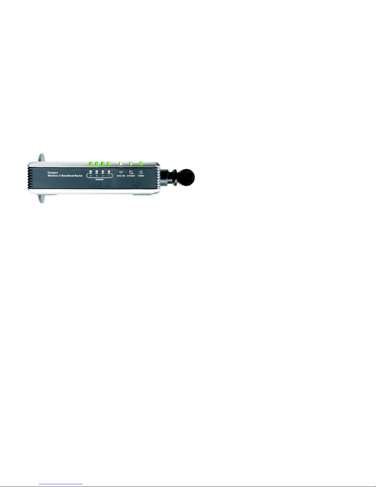
The Front Panel
The Router’s LEDs, which indicate the status of the Router and network activities, are located on the front panel.
ETHERNET 1-4 Green. These numbered LEDs, corresponding with the numbered ports on the Router’s back
panel, serve two purposes. If the LED is continuously lit, the Router is connected to a device
through that port. A flashing LED indicates network activity over that port.
WIRELESS Green. The WIRELESS LED flashes when there is a successful wireless connection.
INTERNET Green. The INTERNET LED lights up when there is a connection through the Internet port.
POWER Green. The POWER LED lights up and will stay on while the Router is powered on. When the
Router goes through its self-diagnostic mode during every boot-up, this LED will flash. When
the diagnostic is complete, the LED will be solidly lit.
Figure 3-2: The Router’s Front Panel
Page 14
8
Chapter 3: Getting to Know the Compact Wireless-G Broadband Router
The Bottom Panel
Compact Wireless-G Broadband Router
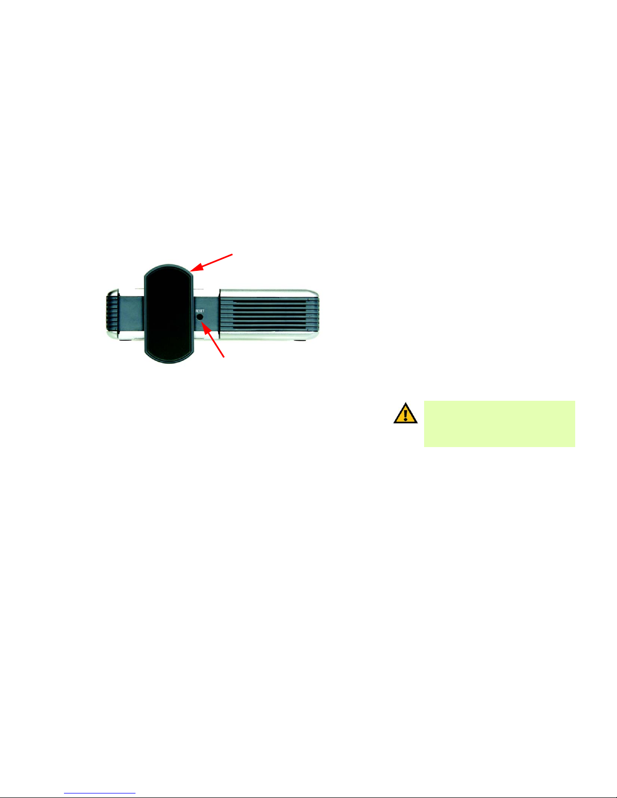
The Bottom Panel
The Router’s Reset button is located on the bottom panel. To access the button, turn the stand perpendicular to
the Router. Use a sharp object like a pencil to push in the button.
RESET Button There are two ways to reset the Router's factory defaults. Either press the RESET button,
for approximately eight seconds, or restore the defaults from the Administration tab Factory Defaults in the Router's Web-based Utility.
IMPORTANT: If you reset the Router, all of your
settings, including Internet connection, wireless,
and security, will be deleted and replaced with the
factory defaults. Do not reset the Router if you
want to retain these settings.
Figure 3-3: The Router’s Bottom Panel
STAND
RESET BUTTON
Page 15
9
Chapter 4: Connecting the Compact Wireless-G Broadband Router
Overview
Compact Wireless-G Broadband Router
Chapter 4: Connecting the Compact Wireless-G
Broadband Router
Overview
Linksys recommends using the Setup Wizard on the Setup CD-ROM for first-time installation of the Router. For
advanced users, you may follow the instructions in this chapter, and then configure the Router through its Webbased Utility (refer to “Chapter 5: Configuring the Compact Wireless-G Broadband Router”).
This chapter includes two sets of instructions. If the Compact Wireless-G Broadband Router will be the only router
in your network, follow the instructions in “Hardware Installation for Connection to Your Broadband Modem.” If
you want to install the Compact Wireless-G Broadband Router behind another router in your network, then follow
the instructions in “Hardware Installation for Connection to Another Router.”
Hardware Installation for Connection to your Broadband Modem
1. Power down your network devices.
2. Locate an optimum location for the Router. The best place for the Router is usually at the center of your
wireless network, with line of sight to all of your wireless devices. Normally, the higher you place the
antenna, the better the performance will be.
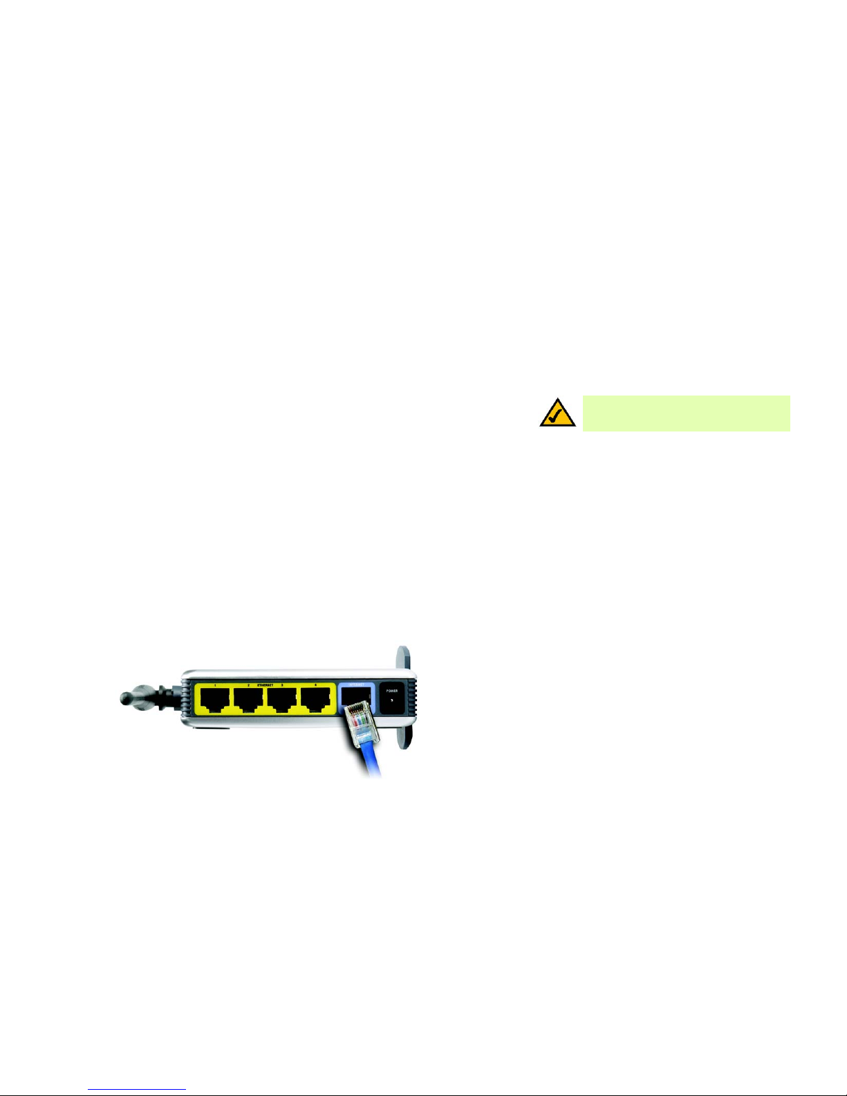
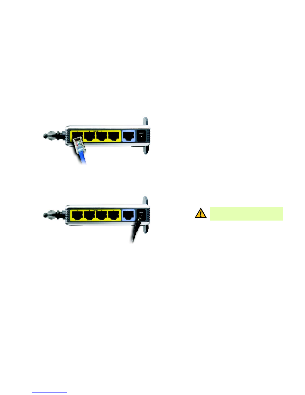
3. Connect a standard Ethernet network cable from the Router’s Internet port to your broadband modem.
Figure 4-1: Connecting your Broadband Modem
NOTE: For first-time installation of the Router,
Linksys recommends using the Setup Wizard on
the Setup CD-ROM.
Page 16
10
Chapter 4: Connecting the Compact Wireless-G Broadband Router
Hardware Installation for Connection to your Broadband Modem
Compact Wireless-G Broadband Router
4. Connect a standard Ethernet network cable from one of the Router’s numbered ports to your network PC or
Ethernet device.
5. Connect the AC power adapter to the Router's Power port. Then connect the other end to an electrical outlet.
Only use the power adapter supplied with the Router. Use of a different adapter can cause product damage.
Now that the hardware installation is complete, proceed to “Chapter 5: Configuring the Compact
Wireless-G Broadband Router.”
Figure 4-2: Connecting Your Network Devices
Figure 4-3: Connecting the Power
IMPORTANT: Make sure you use the power
adapter that is supplied with the Router. Use of a
different power adapter could damage the Router.
Page 17
11
Chapter 4: Connecting the Compact Wireless-G Broadband Router
Hardware Installation for Connection to Another Router
Compact Wireless-G Broadband Router
Hardware Installation for Connection to Another Router
Before you install the Router, you must change the default IP address of the other router. This is mandatory
because both routers may be set to the same IP address by default. If you do not change the other router’s default
IP address, then you may not be able to set up the Router.
First, make sure the Router is NOT connected to your network. Then follow these instructions:
1. To access the other router’s Web-based Utility, launch Internet Explorer or Netscape Navigator, and enter the
other router’s default IP address, 192.168.1.1, in the Address field. Then press Enter.
2. A password request page will appear. Leave the User Name field blank. In the Password field, enter the
password you have set (the default password is admin). Then click the OK button.
3. The first screen that appears will display the Setup tab. In the Network Setup section, there is a setting called
Local IP Address (also called Router IP), which is set to 192.168.1.1. Change this to 192.168.2.1.
4. Click the Save Settings button to save your change, and then exit the Web-based Utility.
5. Power down your network devices. Now you will begin the hardware installation of the Router.
6. Locate an optimum location for the Router. The best place for the Router is usually at the center of your
wireless network, with line of sight to all of your wireless devices. Normally, the higher you place the
antenna, the better the performance will be.
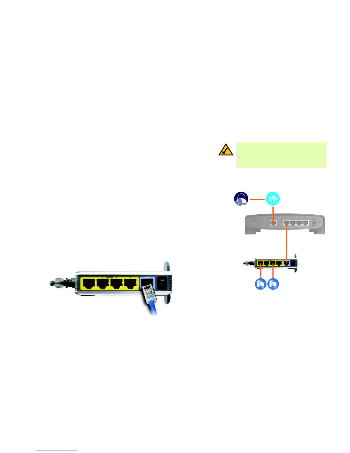
7. Connect a standard Ethernet network cable to the Router’s Internet port. Then, connect the other end of the
Ethernet cable to one of the numbered Ethernet ports on your other router.
Figure 4-4: Diagram for Connection to Another Router
NOTE: Steps 1-4 are instructions for a typical
Linksys router; however, if you are using a nonLinksys router, refer to the other router’s
documentation for instructions on how to change its
local IP address to 192.168.2.1.
Internet
Broadband
Modem
Router
Compact
Wireless-G
Broadband
Router
Figure 4-5: Connecting Another Router
Multiple
PCs
Page 18

12
Chapter 4: Connecting the Compact Wireless-G Broadband Router
Hardware Installation for Connection to Another Router
Compact Wireless-G Broadband Router
8. Decide which network computers or Ethernet devices you want to connect to the Router.
Disconnect the selected computers or devices from the other router, and then connect them to the Router’s
numbered ports using standard Ethernet network cabling.
9. Connect the AC power adapter to the Router's Power port and the other end into an electrical outlet. Only use
the power adapter supplied with the Router. Use of a different adapter may result in product damage.
Now that the hardware installation is complete, proceed to “Chapter 5: Configuring the Compact
Wireless-G Broadband Router.”
Figure 4-6: Connecting Your Network Devices
Figure 4-7: Connecting the Power
IMPORTANT: Make sure you use the power
adapter that is supplied with the Router. Use of a
different power adapter could damage the Router.
Page 19

13
Chapter 5: Configuring the Compact Wireless-G Broadband Router
Overview
Compact Wireless-G Broadband Router
Chapter 5: Configuring the Compact Wireless-G
Broadband Router
Overview
Linksys recommends using the Setup Wizard on the Setup CD-ROM for first-time installation of the Router. For
advanced users, you may follow the instructions in the previous chapter, “Chapter 4: Connecting the Compact
Wireless-G Broadband Router”, and then configure the Router through its Web-based Utility.
This chapter will describe each web page in the Utility and each page’s key functions. The utility can be accessed
via your web browser through use of a computer connected to the Router. For a basic network setup, most users
will use these two screens of the Utility:
• Basic Setup. On the Basic Setup screen, enter the settings provided by your ISP.
• Management. Click the Administration tab and then the Management tab. The Router’s default password is
admin. To secure the Router, change the Password from its default.
There are seven main tabs: Setup, Wireless, Security, Access Restrictions, Applications & Gaming, Administration,
and Status. Additional tabs will be available after you click one of the main tabs.
Make the necessary changes through the Web-based Utility. On each screen, click the Save Settings button to
apply your changes or Cancel Changes to cancel your changes. Help information is shown on the right-hand side
of the screen.
HAVE YOU: Enabled TCP/IP on your PCs? PCs
communicate over the network with this protocol.
Refer to “Appendix D: Windows Help” for more
information on TCP/IP.
NOTE: For first-time installation of the Router,
Linksys recommends using the Setup Wizard on
the Setup CD-ROM.
Page 20
14
Chapter 5: Configuring the Compact Wireless-G Broadband Router
How to Access the Web-based Utility
Compact Wireless-G Broadband Router
How to Access the Web-based Utility
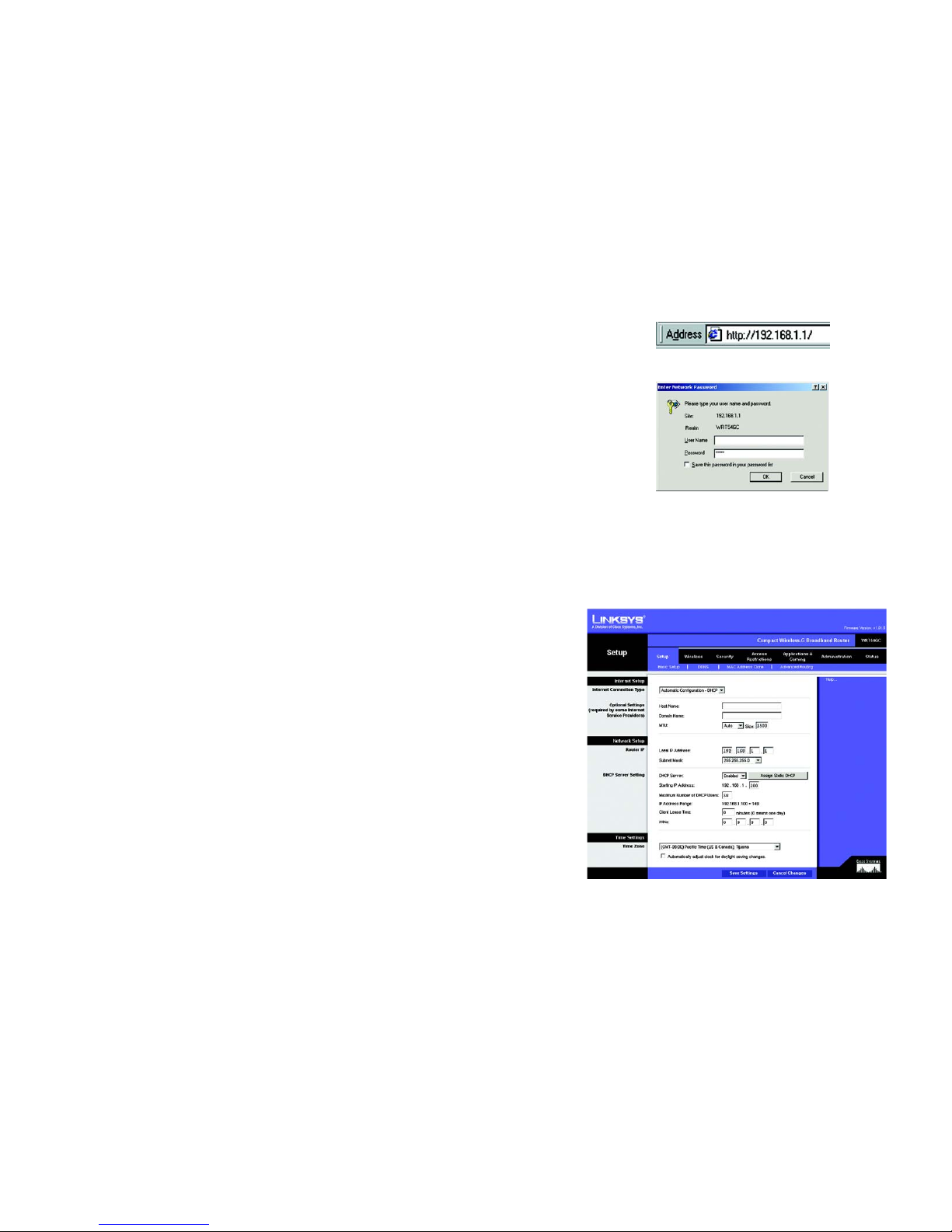
To access the Web-based Utility, launch Internet Explorer or Netscape Navigator, and enter the Router’s default IP
address, 192.168.1.1, in the Address field. Then press Enter.
A password request page will appear. Leave the User Name field blank. The first time you open the Web-based
Utility, use the default password admin. (You can set a new password from the Administration tab’s Management
screen.) Then click the OK button.
The Setup Tab - Basic Setup
The first screen that appears displays the Setup tab. This allows you to change the Router's general settings.
Internet Setup
The Internet Setup section configures the Router to your Internet connection. Most of this information can be
obtained from your ISP.
Internet Connection Type
Choose the type of Internet connection your ISP provides from the drop-down menu.
• Automatic Configuration - DHCP. By default, the Router’s Internet Connection Type is set to Automatic
Configuration - DHCP, which should be kept only if your ISP supports DHCP or you are connecting through a
dynamic IP address.
Figure 5-3: Setup Tab - Basic Setup
Figure 5-1: Router’s IP Address
Figure 5-2: Router Login Screen
ip (internet protocol): a protocol used to send data
over a network.
ip address: the address used to identify a computer
or device on a network.
Page 21
15
Chapter 5: Configuring the Compact Wireless-G Broadband Router
The Setup Tab - Basic Setup
Compact Wireless-G Broadband Router
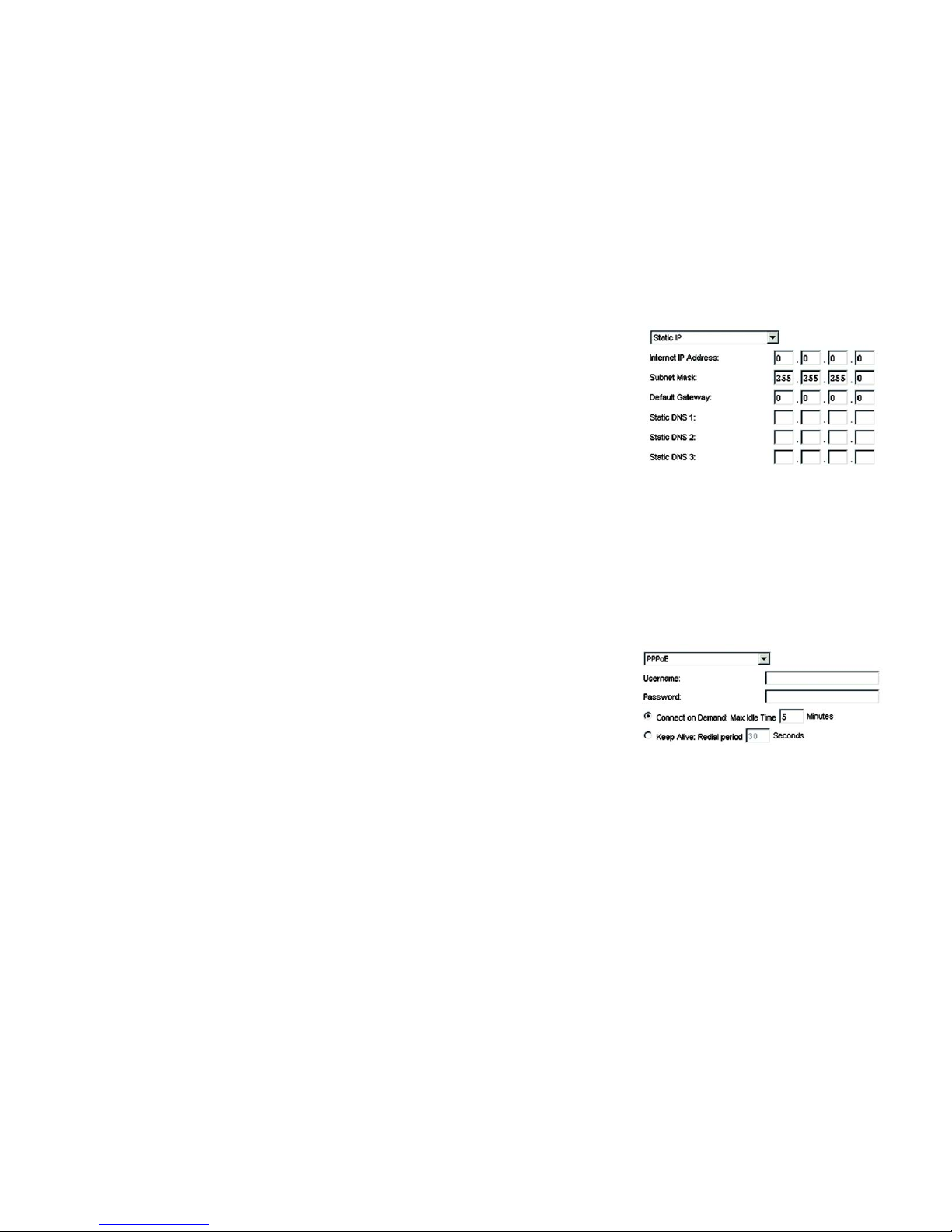
• Static IP. If you are required to use a permanent IP address to connect to the Internet, select Static IP.
Internet IP Address. This is the Router’s IP address, when seen from the Internet. Your ISP will provide you
with the IP Address you need to specify here.
Subnet Mask. This is the Router’s Subnet Mask, as seen by users on the Internet (including your ISP). Your ISP
will provide you with the Subnet Mask.
Default Gateway. Your ISP will provide you with the Gateway Address, which is the ISP server’s IP address.
DNS (1-3). Your ISP will provide you with at least one DNS (Domain Name System) Server IP Address.
• PPPoE. Some DSL-based ISPs use PPPoE (Point-to-Point Protocol over Ethernet) to establish Internet
connections. If you are connected to the Internet through a DSL line, check with your ISP to see if they use
PPPoE. If they do, you will have to enable PPPoE.
User Name and Password. Enter the User Name and Password provided by your ISP.
Connect on Demand: Max Idle Time. You can configure the Router to cut the Internet connection after it has
been inactive for a specified period of time (Max Idle Time). If your Internet connection has been terminated
due to inactivity, Connect on Demand enables the Router to automatically re-establish your connection as
soon as you attempt to access the Internet again. If you wish to activate Connect on Demand, click the radio
button. In the Max Idle Time field, enter the number of minutes you want to have elapsed before your Internet
connection terminates.
Keep Alive Option: Redial Period. If you select this option, the Router will periodically check your Internet
connection. If you are disconnected, then the Router will automatically re-establish your connection. To use
this option, click the radio button next to Keep Alive. In the Redial Period field, you specify how often you want
the Router to check the Internet connection. The default Redial Period is 30 seconds.
• PPTP. Point-to-Point Tunneling Protocol (PPTP) is a service that applies to connections in Europe only.
Specify Internet IP Address. This is the Router’s IP address, as seen from the Internet. Your ISP will provide
you with the IP Address you need to specify here.
Subnet Mask. This is the Router’s Subnet Mask, as seen by users on the Internet (including your ISP). Your ISP
will provide you with the Subnet Mask.
Gateway. Your ISP will provide you with the Gateway Address.
User Name and Password. Enter the User Name and Password provided by your ISP.
Figure 5-5: PPPoE Connection Type
Figure 5-4: Static IP Connection Type
static ip address: a fixed address
assigned to a computer or device
connected to a network.
subnet mask: an address code that
determines the size of the network.
default gateway: a device that forwards
Internet traffic from your local area network.
pppoe: a type of broadband connection that
provides authentication (username and
password) in addition to data transport
Page 22

16
Chapter 5: Configuring the Compact Wireless-G Broadband Router
The Setup Tab - Basic Setup
Compact Wireless-G Broadband Router
Connect on Demand: Max Idle Time. You can configure the Router to cut the Internet connection after it has
been inactive for a specified period of time (Max Idle Time). If your Internet connection has been terminated
due to inactivity, Connect on Demand enables the Router to automatically re-establish your connection as
soon as you attempt to access the Internet again. If you wish to activate Connect on Demand, click the radio
button. In the Max Idle Time field, enter the number of minutes you want to have elapsed before your Internet
connection terminates.
Keep Alive Option: Redial Period. If you select this option, the Router will periodically check your Internet
connection. If you are disconnected, then the Router will automatically re-establish your connection. To use
this option, click the radio button next to Keep Alive. In the Redial Period field, you specify how often you want
the Router to check the Internet connection. The default Redial Period is 30 seconds.
Optional Settings
Some of these settings may be required by your ISP. Verify with your ISP before making any changes.
Host Name and Domain Name. These fields allow you to supply a host and domain name for the Router. Some
ISPs, usually cable ISPs, require these names as identification. You may have to check with your ISP to see if your
broadband Internet service has been configured with a host and domain name. In most cases, leaving these
fields blank will work.
MTU. MTU is the Maximum Transmission Unit. It specifies the largest packet size permitted for Internet
transmission. Select Manual if you want to manually enter the largest packet size that will be transmitted. The
recommended size, entered in the Size field, is 1500. You should leave this value in the 1200 to 1500 range. To
have the Router select the best MTU for your Internet connection, keep the default setting, Auto.
Network Setup
The Network Setup section changes the Router’s local network settings. Changes to the Router’s wireless
network settings are performed through the Wireless tab.
Router IP
IP Address and Subnet Mask. This shows both the Router’s IP Address and Subnet Mask, as seen by your
network. The default IP Address is 192.168.1.1, and the default Subnet Mask is 255.255.255.0. In most cases,
keeping the default values will work.
Figure 5-6: PPTP Connection Type
packet: a unit of data sent over a network
Page 23
17
Chapter 5: Configuring the Compact Wireless-G Broadband Router
The Setup Tab - Basic Setup
Compact Wireless-G Broadband Router
DHCP Server Settings
The settings allow you to configure the Router’s Dynamic Host Configuration Protocol (DHCP) server function. The
Router can be used as a DHCP server for your network. A DHCP server automatically assigns an IP address to
each computer on your network. If you choose to enable the Router’s DHCP server option, you must make sure
there is no other DHCP server on your network.
DHCP Server. DHCP is enabled by factory default. If you already have a DHCP server on your network, or you
don’t want a DHCP server, then select Disabled (no other DHCP features will be available).
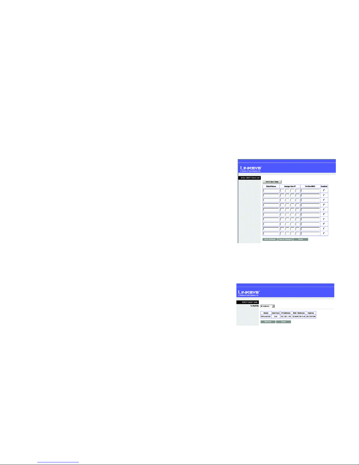
Assign Static DHCP. Every time a PC reboots, it is assigned a new local IP address by the Router. If you want a PC
to be assigned the same IP address every time it reboots, then click the Assign Static IP button.
On the Static DHCP Client List screen, enter a client name, then enter the static local IP address in the Assign this
IP field, and enter the MAC address of the PC in the To this MAC field. Then click the Enabled checkbox. When you
have finished your entries, click the Save Settings button to save your changes. Click the Cancel Changes
button to cancel your changes. To exit this screen, click the Close button.
If you want to see a list of DHCP clients, click the DHCP Client Table button. On the DHCP Client Table screen, you
will see a list of DHCP clients with the following information: Client Names, Interfaces, IP Addresses, and MAC
Addresses. From the To Sort by drop-down menu, you can sort the table by Client Name, Interface, IP Address, or
MAC Address. To view the most up-to-date information, click the Refresh button. To exit this screen, click the
Close button.
Start IP Address. Enter a value for the DHCP server to start with when issuing IP addresses. Because the
Router’s default IP address is 192.168.1.1, the Starting IP Address must be 192.168.1.2 or greater, but smaller
than 192.168.1.254. The default Starting IP Address is 192.168.1.100.
Maximum Number of Users. Enter the maximum number of PCs that you want the DHCP server to assign IP
addresses to. This number cannot be greater than 253. The default is 50.
IP Address Range. The range of DHCP addresses is displayed here.
Client Lease Time. The Client Lease Time is the amount of time a network user will be allowed connection to the
Router with their current dynamic IP address. Enter the amount of time, in minutes, that the user will be “leased”
this dynamic IP address. After the time is up, the user will be automatically assigned a new dynamic IP address.
The default is 0 minutes, which means one day.
WINS. The Windows Internet Naming Service (WINS) manages each PC’s interaction with the Internet. If you use
a WINS server, enter that server’s IP Address here. Otherwise, leave this blank.
Figure 5-7: Static DHCP Client List
Figure 5-8: DHCP Client Table
dynamic ip address: a temporary IP
address assigned by a DHCP server.
Page 24

18
Chapter 5: Configuring the Compact Wireless-G Broadband Router
The Setup Tab - DDNS
Compact Wireless-G Broadband Router
Time Settings
Change the time zone in which your network functions from this pull-down menu. Click the checkbox if you want
the Router to automatically adjust for daylight savings time.
Change these settings as described here and click the Save Settings button to apply your changes or Cancel
Changes to cancel your changes. Help information is shown on the right-hand side of the screen.
The Setup Tab - DDNS
The Router offers a Dynamic Domain Name System (DDNS) feature. DDNS lets you assign a fixed host and domain
name to a dynamic Internet IP address. It is useful when you are hosting your own website, FTP server, or other
server behind the Router.
Before you can use this feature, you need to sign up for DDNS service at one of two DDNS service providers, DynDNS.org or
TZO.com. If you do not want to use this feature, keep the default setting, Disable.
DDNS
DDNS Service. If your DDNS service is provided by DynDNS.org, then select DynDNS.org from the drop-down
menu. If your DDNS service is provided by TZO, then select TZO.com. The features available on the DDNS screen
will vary, depending on which DDNS service provider you use.
DynDNS.org
User Name, Password, and Host Name. Enter the User Name, Password, and Host Name of the account you
set up with DynDNS.org.
Internet IP Address. The Router’s current Internet IP Address is displayed here. Because it is dynamic, it will
change.
Status. The status of the DDNS service connection is displayed here.
Figure 5-9: DynDNS.org
Page 25
19
Chapter 5: Configuring the Compact Wireless-G Broadband Router
The Setup Tab - MAC Address Clone
Compact Wireless-G Broadband Router
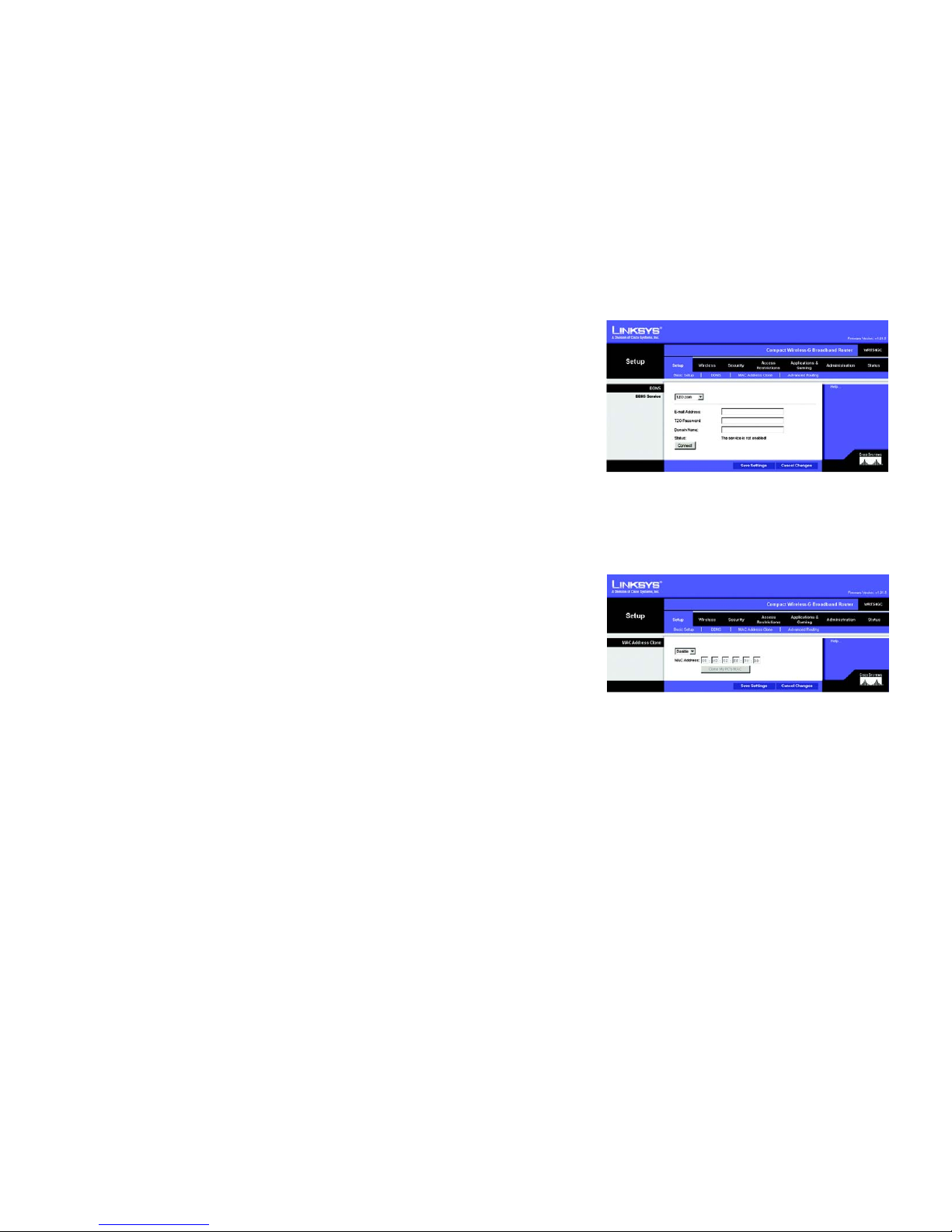
TZO.com
E-mail Address, Password, and Domain Name. Enter the Email Address, Password, and Domain Name of
the service you set up with TZO.
Internet IP Address. The Router’s current Internet IP Address is displayed here. Because it is dynamic, this
will change.
Status. The status of the DDNS service connection is displayed here.
When you have finished making changes to this screen, click the Save Settings button to apply your changes or
Cancel Changes to cancel your changes. Help information is shown on the right-hand side of the screen.
The Setup Tab - MAC Address Clone
A MAC address is a 12-digit code assigned to a unique piece of hardware for identification. Some ISPs will
require you to register a MAC address in order to access the Internet. If you do not wish to re-register the MAC
address with your ISP, you may assign the MAC address you have currently registered with your ISP to the Router
with the MAC Address Clone feature.
MAC Address Clone
Enabled/Disabled. To have the MAC Address cloned, select Enabled from the drop-down menu.
MAC Address. Enter the MAC Address registered with your ISP here.
Clone My PC’s MAC. Clicking this button will clone the MAC address of the PC you are currently using.
Change these settings as described here and click the Save Settings button to apply your changes or Cancel
Changes to cancel your changes. Help information is shown on the right-hand side of the screen.
Figure 5-11: Setup Tab - MAC Address Clone
mac address: the unique address that a
manufacturer assigns to each networking device.
Figure 5-10: TZO.com
Page 26

20
Chapter 5: Configuring the Compact Wireless-G Broadband Router
The Setup Tab - Advanced Routing
Compact Wireless-G Broadband Router
The Setup Tab - Advanced Routing
This tab is used to set up the Router’s advanced functions. Operating Mode allows you to select the type(s) of
advanced functions you use. Dynamic Routing will automatically adjust how packets travel on your network. Static
Routing sets up a fixed route to another network destination.
Operating Mode
. Select the mode in which this Router will function. If this Router is hosting your network’s
connection to the Internet, select
Gateway
. If another Router exists on your network, select
Router
. When Router is
chosen,
Dynamic Routing
will be enabled.
Dynamic Routing
. This feature enables the Router to automatically adjust to physical changes in the network’s
layout and exchange routing tables with the other router(s). The Router determines the network packets’ route
based on the fewest number of hops between the source and the destination. This feature is
Disabled
by default.
From the drop-down menu, you can also select
LAN & Wireless
, which performs dynamic routing over your
Ethernet and wireless networks. You can also select
WAN
, which performs dynamic routing with data coming from
the Internet. Finally, selecting
Both
enables dynamic routing for both networks, as well as data from the Internet.
Static Routing
. To set up a static route between the Router and another network, select a number from the Static
Routing drop-down list. (A static route is a pre-determined pathway that network information must travel to reach a
specific host or network.) Enter the information described below to set up a new static route. (Click the
Delete This
Entry
button to delete a static route.)
Enter Route Name
. Enter a name for the Route here, using a maximum of 25 alphanumeric characters.
Destination LAN IP
. The Destination LAN IP is the address of the remote network or host to which you want to
assign a static route.
Subnet Mask
. The Subnet Mask determines which portion of a Destination LAN IP address is the network
portion, and which portion is the host portion.
Default Gateway
. This is the IP address of the gateway device that allows for contact between the Router and
the remote network or host.
Interface
. This interface tells you whether the Destination IP Address is on the
LAN & Wireless
(Ethernet and
wireless networks), the
WAN
(Internet), or a dummy network in which one PC acts like a network—necessary
for certain software programs).
Click the
Show Routing Table
button to view the Static Routes you’ve already set up.
Change these settings as described here and click the
Save Settings
button to apply your changes or
Cancel
Changes
to cancel your changes.
Figure 5-12: Setup Tab - Advanced Routing (Gateway)
Figure 5-13: Setup Tab - Advanced Routing (Router)
Page 27

21
Chapter 5: Configuring the Compact Wireless-G Broadband Router
The Wireless Tab - Basic Wireless Settings
Compact Wireless-G Broadband Router
The Wireless Tab - Basic Wireless Settings
The basic settings for wireless networking are set on this screen.
Wireless Network
Wireless-G Settings
Mode. From this drop-down menu, you can select the wireless standards running on your network. If you have
both 802.11g and 802.11b devices in your network, keep the default setting, Mixed. If you have only 802.11g
devices, select G Only. If you have only 802.11b devices, select B Only.
Network Name (SSID). The SSID is the network name shared by all devices in a wireless network. The SSID
must be identical for all devices in the wireless network. It is case-sensitive and must not exceed 32 keyboard
characters in length. Make sure this setting is the same for all devices in your wireless network. For added
security, you should change the default SSID (linksys) to a unique name.
Channel. Select the appropriate channel from the list provided to correspond with your network settings. All
devices in your wireless network must broadcast on the same channel in order to communicate.
SSID Broadcast. When wireless clients survey the local area for wireless networks to associate with, they will
detect the SSID broadcast by the Router. To broadcast the Router's SSID, keep the default setting, Enabled. If you
do not want to broadcast the Router's SSID, then select Disabled.
Change these settings as described here and click the Save Settings button to apply your changes or Cancel
Changes to cancel your changes. Help information is shown on the right-hand side of the screen.
Figure 5-14: Wireless Tab - Basic Wireless Settings
Page 28
22
Chapter 5: Configuring the Compact Wireless-G Broadband Router
The Wireless Tab - Wireless Security
Compact Wireless-G Broadband Router
The Wireless Tab - Wireless Security
The Wireless Security settings configure the security of your wireless network. There are three wireless security
mode options supported by the Router: WPA Personal, WPA2 Personal, WPA2 Mixed Mode and WEP. (WEP stands
for Wired Equivalent Privacy). These four are briefly discussed here. For detailed instructions on configuring
wireless security for the Router, turn to “Appendix B: Wireless Security.”
Wireless Security
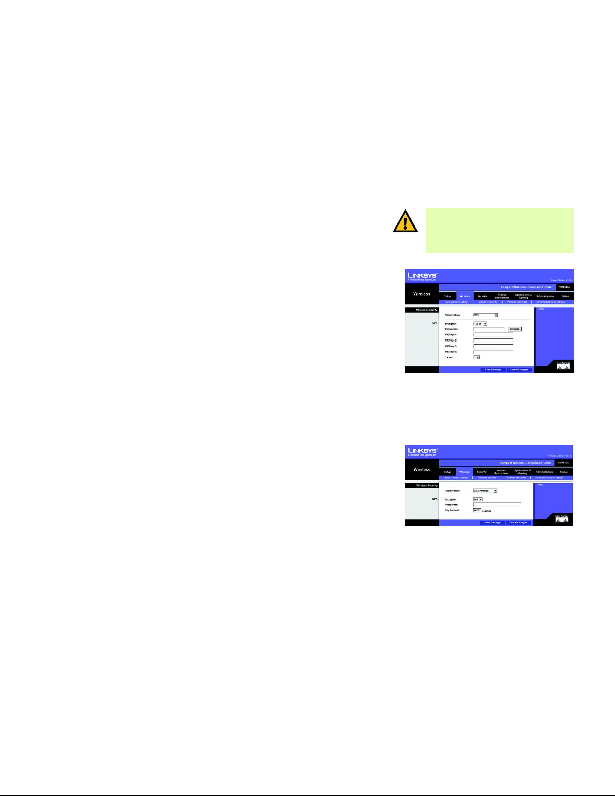
WEP. WEP is a basic encryption method. Select a level of WEP encryption, 64-bit or 128-bit. If you want to use a
Passphrase, then enter it in the Passphrase field and click the Generate button. If you want to enter the WEP key
manually, then enter it in the WEP Key 1-4 field(s). To indicate which WEP key to use, select the appropriate TX
Key number.
WPA Personal. This method offers two encryption methods, TKIP and AES, with dynamic encryption keys. Select
the type of encryption method you want to use, TKIP or AES. Enter the Passphrase, which can have 8 to 63
characters. Then enter the Key Renewal period, which instructs the Router how often it should change the
encryption keys.
Figure 5-15: Wireless Tab - Wireless Security
(WEP)
Figure 5-16: Wireless Tab - Wireless Security
(WPA Personal)
wep (wired equivalent privacy): a method of
encrypting network data transmitted on a
wireless network for greater security.
IMPORTANT: If you are using encryption, always
remember that each device in your wireless
network MUST use the same encryption method
and encryption key, or else your wireless network
will not function properly.
Page 29
23
Chapter 5: Configuring the Compact Wireless-G Broadband Router
The Wireless Tab - Wireless Security
Compact Wireless-G Broadband Router
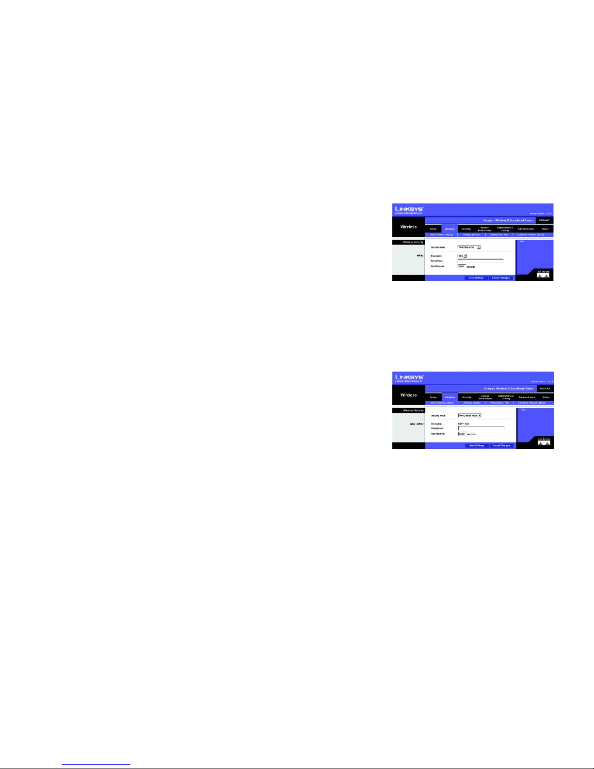
Figure 5-18: Wireless Tab - Wireless Security
(WPA2 Mixed Mode)
WPA2 Personal. WPA2 gives you one encryption method, AES, with dynamic encryption keys. Enter a
Passphrase of 8-63 characters. Then enter a Group Key Renewal period, which instructs the Router how often it
should change the encryption keys.
WPA2 Mixed Mode. WPA2 gives you TKIP+AES encryption. Enter a Passphrase of 8-63 characters. Then enter a
Group Key Renewal period, which instructs the Router how often it should change the encryption keys.
Figure 5-17: Wireless Tab - Wireless Security
(WPA2 Personal)
Page 30
24
Chapter 5: Configuring the Compact Wireless-G Broadband Router
The Wireless Tab - Wireless MAC Filter
Compact Wireless-G Broadband Router
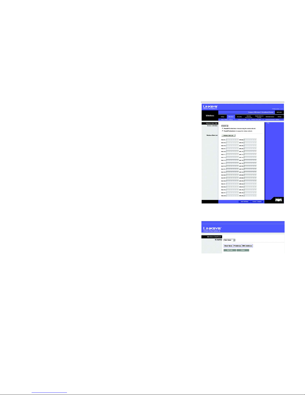
The Wireless Tab - Wireless MAC Filter
Wireless access can be filtered by using the MAC addresses of the wireless devices transmitting within your
network’s radius.
Wireless MAC Filter
Access Restrictions
To filter wireless users by MAC Address, either permitting or blocking access, click Enabled. If you do not wish to
filter users by MAC Address, select Disabled.
Prevent PCs listed below from accessing the wireless network. Clicking this radio button will block wireless
access by MAC Address.
Permit PCs listed below to access the wireless network. Clicking this radio button will allow wireless access
by MAC Address.
Wireless Client List
Wireless Client List. Click the Wireless Client MAC List button to display a list of network users by MAC
Address.From the To S ort by drop-down menu, you can sort the table by Client Name, IP Address, or MAC
Address. To view the most up-to-date information, click the Refresh button. To exit this screen, click the Close
button.
List users, by MAC Address, whose wireless access you want to control.
Change these settings as described here and click the Save Settings button to apply your changes or Cancel
Changes to cancel your changes. Help information is shown on the right-hand side of the screen.
Figure 5-19: Wireless Tab - Wireless MAC Filter
Figure 5-20: Wireless Tab - Wireless Client List
Page 31

25
Chapter 5: Configuring the Compact Wireless-G Broadband Router
The Wireless Tab - Advanced Wireless Settings
Compact Wireless-G Broadband Router
The Wireless Tab - Advanced Wireless Settings
This tab is used to set up the Router’s advanced wireless functions. These settings should only be adjusted by an
expert administrator as incorrect settings can reduce wireless performance.
Advanced Wireless
Wireless-G Settings
Authentication Type. The default is set to Auto (Default), allows either Open System or Shared Key
authentication to be used. With Open System authentication, the sender and the recipient do NOT use a WEP key
for authentication. With Shared Key authentication, the sender and recipient use a WEP key for authentication.
Transmission Rate. The rate of data transmission should be set depending on the speed of your wireless
network. You can select from a range of transmission speeds, or you can select Auto (Default) to have the
Router automatically use the fastest possible data rate and enable the Auto-Fallback feature. Auto-Fallback will
negotiate the best possible connection speed between the Router and a wireless client. The default value is Auto
(Default).
Basic Rate. The Basic Rate setting is not actually one rate of transmission but a series of rates at which the
Router can transmit. The Router will advertise its Basic Rate to the other wireless devices in your network, so
they know which rates will be used. The Router will also advertise that it will automatically select the best rate
for transmission. The default setting is Default, when the Router can transmit at all standard wireless rates
(1-2Mbps, 5.5Mbps, 11Mbps, 18Mbps, and 24Mbps). Other options are 1-2Mbps, for use with older wireless
technology, and All, when the Router can transmit at all wireless rates. The Basic Rate is not the actual rate of
data transmission. If you want to specify the Router’s rate of data transmission, configure the Transmission Rate
setting.
CTS Protection Mode. CTS (Clear-To-Send) Protection Mode should be set to Auto (Default). The Router will
automatically use CTS Protection Mode when your Wireless-G products are experiencing severe problems and
are not able to transmit to the Router in an environment with heavy 802.11b traffic. This function boosts the
Router’s ability to catch all Wireless-G transmissions but will severely decrease performance.
DTIM Interval. This value indicates the interval of the Delivery Traffic Indication Message (DTIM). A DTIM field is
a countdown field informing clients of the next window for listening to broadcast and multicast messages. When
the Router has buffered broadcast or multicast messages for associated clients, it sends the next DTIM with a
DTIM Interval value. Its clients hear the beacons and awaken to receive the broadcast and multicast messages.
The default value is 1.
Figure 5-21: Wireless Tab - Advanced Wireless
Settings
cts (clear to send): a signal sent by a wireless
device, signifying that it is ready to receive data.
dtim: a message included in data packets
that can increase wireless efficiency.
Page 32

26
Chapter 5: Configuring the Compact Wireless-G Broadband Router
The Wireless Tab - Advanced Wireless Settings
Compact Wireless-G Broadband Router
Fragmentation Threshold. This value specifies the maximum size for a packet before data is fragmented into
multiple packets. If you experience a high packet error rate, you may slightly increase the Fragmentation
Threshold. Setting the Fragmentation Threshold too low may result in poor network performance. Only minor
reduction of the default value is recommended. In most cases, it should remain at its default value of 2346.
RTS Threshold. Should you encounter inconsistent data flow, only minor reduction of the default value, 2347, is
recommended. If a network packet is smaller than the preset RTS threshold size, the RTS/CTS mechanism will
not be enabled. The Router sends Request to Send (RTS) frames to a particular receiving station and negotiates
the sending of a data frame. After receiving an RTS, the wireless station responds with a Clear to Send (CTS)
frame to acknowledge the right to begin transmission. The RTS Threshold value should remain at its default value
of 2347.
Beacon Interval. The default value is 100. The Beacon Interval value indicates the frequency interval of the
beacon. A beacon is a packet broadcast by the Router to synchronize the wireless network.
Change these settings as described here and click the Save Settings button to apply your changes or Cancel
Changes to cancel your changes. Help information is shown on the right-hand side of the screen.
beacon interval: data transmitted on your wireless
network that keeps the network synchronized.
fragmentation: breaking a packet into smaller units
when transmitting over a network medium that
cannot support the original size of the packet.
Page 33

27
Chapter 5: Configuring the Compact Wireless-G Broadband Router
The Security Tab - Firewall
Compact Wireless-G Broadband Router
The Security Tab - Firewall
The Firewall screen offers Filters and the option to Block WAN Requests. Filters block specific Internet data types
and block anonymous Internet requests. To enable a feature, select Enabled from the drop-down menu. To
disable a feature, select Disabled from the drop-down menu.
Firewall
• SPI Firewall Protection. Enable this feature to employ Stateful Packet Inspection (SPI) for more detailed
review of data packets entering your network environment.
• Block Anonymous Internet Requests. When enabled, this feature keeps your network from being “pinged,” or
detected, by other Internet users. It also reinforces your network security by hiding your network ports. Both
functions of this feature make it more difficult for outside users to work their way into your network. This
feature is enabled by default. Select Disabled to allow anonymous Internet requests.
• Filter Multicast. Multicasting allows for multiple transmissions to specific recipients at the same time. If
multicasting is permitted, then the Router will allow IP multicast packets to be forwarded to the appropriate
computers. Select Enable to filter multicasting, or Disable to disable this feature.
• Filter Internet NAT Redirection. This feature uses port forwarding to block access to local servers from local
networked computers. Check the box to enable filter Internet NAT redirection, or uncheck the box to disable
this feature.
• Web Filters
Proxy. Use of WAN proxy servers may compromise the Gateway's security. Denying Filter Proxy will disable
access to any WAN proxy servers. To enable proxy filtering, click the checkbox.
Java. Java is a programming language for websites. If you deny Java, you run the risk of not having access to
Internet sites created using this programming language. To enable Java filtering, click the checkbox.
ActiveX. ActiveX is a programming language for websites. If you deny ActiveX, you run the risk of not having
access to Internet sites created using this programming language. To enable ActiveX filtering, click the
checkbox.
Cookies. A cookie is data stored on your computer and used by Internet sites when you interact with them. To
enable cookie filtering, click the checkbox.
Change these settings as described here and click the Save Settings button to apply your changes or Cancel
Changes to cancel your changes. Help information is shown on the right-hand side of the screen.
Figure 5-22: Security Tab - Firewall
Page 34

28
Chapter 5: Configuring the Compact Wireless-G Broadband Router
The Security Tab - VPN Passthrough
Compact Wireless-G Broadband Router
The Security Tab - VPN Passthrough
Use the settings on this tab to allow VPN tunnels using IPSec, L2TP, or PPTP protocols to pass through the
Router’s firewall.
VPN Passthrough
IPSec Passthrough. Internet Protocol Security (IPSec) is a suite of protocols used to implement secure exchange
of packets at the IP layer. IPSec Pass-Through is enabled by default. To disable IPSec Passthrough, select
Disabled.
L2TP Passthrough. Layer 2 Tunneling Protocol is the method used to enable Point-to-Point sessions via the
Internet on the Layer 2 level. L2TP Pass-Through is enabled by default. To disable L2TP Passthrough, select
Disabled.
PPTP Passthrough. Point-to-Point Tunneling Protocol (PPTP) allows the Point-to-Point Protocol (PPP) to be
tunneled through an IP network. PPTP Pass-Through is enabled by default. To disable PPTP Passthrough, select
Disabled.
Change these settings as described here and click the Save Settings button to apply your changes or Cancel
Changes to cancel your changes. Help information is shown on the right-hand side of the screen.
The Access Restrictions Tab - Internet Access Policy
The Internet Access Policy screen allows you to block or allow specific kinds of Internet usage and traffic, such as
Internet access, designated applications, websites, and inbound traffic during specific days and times.
Internet Access Policy
Access Policy. Access can be managed by a policy. Use the settings on this screen to establish an access policy
(after the Save Settings button is clicked). Selecting a policy from the drop-down menu will display that policy’s
settings. To delete a policy, select that policy’s number and click the Delete This Policy button. To view all the
policies, click the Summary button.
On the Summary screen, the policies are listed with the following information: No., Policy Name, Access, Days,
Time, and status (Enabled). You can change the type of access, days, and times of a policy. To activate a policy,
click the Enabled checkbox. To delete a policy, click its Delete button. Click the Save Settings button to save
your changes, or click the Cancel Changes button to cancel your changes. To return to the Internet Access Policy
tab, click the Close button. To view the list of PCs for a specific policy, click the PCs List button.
ipsec: a VPN protocol used to implement
secure exchange of packets at the IP layer.
pptp: a VPN protocol that allows the Point to Point
Protocol (PPP) to be tunneled through an IP network.
This protocol is also used as a type of broadband
connection in Europe.
Figure 5-23: Security Tab - VPN Passthrough
Figure 5-24: Access Restrictions Tab - Internet
Access Policy
Page 35

29
Chapter 5: Configuring the Compact Wireless-G Broadband Router
The Access Restrictions Tab - Internet Access Policy
Compact Wireless-G Broadband Router
Figure 5-25: Access Restrictions Tab - Summary
Figure 5-26: Access Restrictions Tab - Internet Access
PCs List
On the Internet Access PCs List screen, you can select a PC by MAC Address or IP Address. You can also enter a
range of IP Addresses if you want this policy to affect a group of PCs. After making your changes, click the Save
Settings button to apply your changes or Cancel Changes to cancel your changes. Click the Close button to exit
this screen.
To create an Internet Access policy:
1. Select a number from the Access Policy drop-down menu.
2. Enter a Policy Name in the field provided.
3. To enable this policy, select Enable from the Status drop-down menu.
4. Click the Edit List button to select which PCs will be affected by the policy. The Internet Access PCs List
screen will appear. You can select a PC by MAC Address or IP Address. You can also enter a range of IP
Addresses if you want this policy to affect a group of PCs. After making your changes, click the Save Settings
button to apply your changes or Cancel Changes to cancel your changes. Then click the Close button.
5. Click the appropriate option, Deny or Allow, depending on whether you want to block or allow Internet access
for the PCs you listed on the List of PCs screen.
6. Decide which days and what times you want this policy to be enforced. Select the individual days during
which the policy will be in effect, or select Everyday. Then enter a range of hours and minutes during which
the policy will be in effect, or select 24 Hours.
7. You can filter access to various applications accessed over the Internet, such as FTP or telnet, by selecting up
to three applications from the drop-down menus next to Blocked Application Port.
The Block Services menu offers a choice of ten preset applications. For the preset applications you select, the
appropriate range of ports will automatically be displayed. Click the >> button to add to the Blocked Services
list.
If the application you want to block is not listed or you want to edit an application’s settings, then create a
new one by entering a Service Name, Protocol, and Port Range. Then, click Add.
8. You can also block access by URL address by entering it in the Website Blocking by URL Address field or by
Keyword by entering it in the Website Blocking by Keyword field.
9. Click the Save Settings button to save the policy’s settings. To cancel the policy’s settings, click the Cancel
Changes button.
Page 36

30
Chapter 5: Configuring the Compact Wireless-G Broadband Router
The Applications and Gaming Tab - Port Range Forwarding
Compact Wireless-G Broadband Router
The Applications and Gaming Tab - Port Range Forwarding
The Port Range Forwarding screen allows you to set up public services on your network, such as web servers, ftp
servers, e-mail servers, or other specialized Internet applications. (Specialized Internet applications are any
applications that use Internet access to perform functions such as videoconferencing or online gaming. Some
Internet applications may not require any forwarding.)
Before using forwarding, you should assign static IP addresses to the designated PCs.
Port Range Forwarding
To forward a port, enter the information on each line for the criteria required. Descriptions of each criteria are
described here.
Application Name. Each drop-down menu offers a choice of ten preset applications (select None if you do not
want to use any of the preset applications). Select up to five preset applications. For custom applications, enter
the name of your application in one of the available fields.
The preset applications are among the most widely used Internet applications. They include the following:
DNS (Domain Name System). The way that Internet domain names are located and translated into IP addresses. A
domain name is a meaningful and easy-to-remember “handle” for an Internet address.
Finger. A UNIX command widely used on the Internet to find out information about a particular user, such as a
telephone number, whether the user is currently logged on, and the last time the user was logged on. The person
being “fingered” must have placed his or her profile on the system in order for the information to be available.
Fingering requires entering the full user@domain address.
FTP (File Transfer Protocol). A protocol used to transfer files over a TCP/IP network (Internet, UNIX, etc.). For
example, after developing the HTML pages for a website on a local machine, they are typically uploaded to the
web server using FTP.
POP3 (Post Office Protocol 3). A standard mail server commonly used on the Internet. It provides a message store
that holds incoming e-mail until users log on and download it. POP3 is a simple system with little selectivity. All
pending messages and attachments are downloaded at the same time. POP3 uses the SMTP messaging protocol.
SMTP (Simple Mail Transfer Protocol). The standard e-mail protocol on the Internet. It is a TCP/IP protocol that
defines the message format and the message transfer agent (MTA), which stores and forwards the mail.
Figure 5-27: Applications and Gaming Tab - Port
Range Forwarding
Page 37

31
Chapter 5: Configuring the Compact Wireless-G Broadband Router
The Applications and Gaming Tab - Port Range Forwarding
Compact Wireless-G Broadband Router
SNMP (Simple Network Management Protocol). A widely used network monitoring and control protocol. Data is
passed from SNMP agents, which are hardware and/or software processes reporting activity in each network
device (hub, router, bridge, etc.) to the workstation console used to oversee the network. The agents return
information contained in a MIB (Management Information Base), which is a data structure that defines what is
obtainable from the device and what can be controlled (turned off, on, etc.).
Tel ne t. A terminal emulation protocol commonly used on Internet and TCP/IP-based networks. It allows a user at
a terminal or computer to log onto a remote device and run a program.
TFTP (Trivial File Transfer Protocol). A version of the TCP/IP FTP protocol that has no directory or password
capability.
Web. The Internet.
Start/End. This is the port range. Enter the port number or range of external ports used by the server or Internet
application. Check with the software documentation of the Internet application for more information.
Protocol. Select the protocol(s) used for this application, TCP and/or UDP.
To I P Add ress. For each application, enter the IP address of the PC running the specific application.
Enabled. Click the Enabled checkbox to enable port forwarding for the relevant application.
Change these settings as described here and click the Save Settings button to apply your changes or Cancel
Changes to cancel your changes. Help information is shown on the right-hand side of the screen.
tcp: a network protocol for transmitting data
that requires acknowledgement from the
recipient of data sent.
udp: a network protocol for transmitting data
that does not require acknowledgement from
the recipient of the data that is sent.
Page 38

32
Chapter 5: Configuring the Compact Wireless-G Broadband Router
The Applications & Gaming Tab - Port Range Triggering
Compact Wireless-G Broadband Router
The Applications & Gaming Tab - Port Range Triggering
The Port Range Triggering screen allows the Router to watch outgoing data for specific port numbers. The IP
address of the computer that sends the matching data is remembered by the Router, so that when the requested
data returns through the Router, the data is pulled back to the proper computer by way of IP address and port
mapping rules.
Port Range Triggering
Application Name. Enter the application name of the trigger.
Triggered Range. For each application, list the triggered port number range. Check with the Internet application
documentation for the port number(s) needed. In the first field, enter the starting port number of the Triggered
Range. In the second field, enter the ending port number of the Triggered Range.
Forwarded Range. For each application, list the forwarded port number range. Check with the Internet
application documentation for the port number(s) needed. In the first field, enter the starting port number of the
Forwarded Range. In the second field, enter the ending port number of the Forwarded Range.
Enabled. Click the Enabled checkbox to enable port range triggering for the relevant application.
Change these settings as described here and click the Save Settings button to apply your changes or Cancel
Changes to cancel your changes. Help information is shown on the right-hand side of the screen.
Figure 5-28: Applications and Gaming Tab -
Port Triggering
Page 39

33
Chapter 5: Configuring the Compact Wireless-G Broadband Router
The Applications and Gaming Tab - DMZ
Compact Wireless-G Broadband Router
The Applications and Gaming Tab - DMZ
The DMZ feature allows one network user to be exposed to the Internet for use of a special-purpose service such
as Internet gaming or videoconferencing. DMZ hosting forwards all the ports at the same time to one PC. The Port
Range Forwarding feature is more secure because it only opens the ports you want to have opened, while DMZ
hosting opens all the ports of one computer, exposing the computer to the Internet.
Any PC whose port is being forwarded must have its DHCP client function disabled and should have a new static
IP address assigned to it because its IP address may change when using the DHCP function.
DMZ
To expose one PC, select Enable, then enter a WAN IP Address or Host IP Address in the field.
Wan IP Address. The Internet IP address of the computer you want to expose.
Host IP Address. Enter the IP address of the computer you want to expose.
Change these settings as described here and click the Save Settings button to apply your changes or Cancel
Changes to cancel your changes. Help information is shown on the right-hand side of the screen.
Figure 5-29: Applications and Gaming Tab - DMZ
Page 40

34
Chapter 5: Configuring the Compact Wireless-G Broadband Router
The Administration Tab - Management
Compact Wireless-G Broadband Router
The Administration Tab - Management
This section of the Administration tab allows the network’s administrator to manage specific Router functions for
access and security.
Management
Router Password
Router Password and Re-enter to Confirm. You can change the Router’s password from here. Enter a new
Router password and then type it again in the Re-enter to Confirm field to confirm.
Remote Router Access
Remote Management. To access the Router remotely, from outside the local network, select Enabled.
Otherwise, keep the default setting, Disabled.
Remote Upgrade. If you want to be able to upgrade the Router remotely, from outside the local network, select
Enabled. (You must have the Remote Management feature enabled as well.) Otherwise, keep the default setting,
Disabled.
Allow Remote IP Address. If you want to be able to access the Router from any external IP address, select Any
IP Address. If you want to specify an external IP address or range of IP addresses, then select the second option
and complete the fields provided.
Remote Management Port. Enter the port number that will be open to outside access.
UPnP
Universal Plug and Play (UPnP) allows Windows Me and XP to automatically configure the Router for various
Internet applications, such as gaming and videoconferencing.
UPnP. If you want to use UPnP, keep the default setting, Enabled. Otherwise, select Disabled.
Allow Users to Configure. Keep the default setting, Enabled, if you want to be able to make manual changes to
the Router while using the UPnP feature. Otherwise, select Disabled.
Allow Users to Disable Internet Access. Keep the default setting, Enabled, if you want to be able to prohibit
any and all Internet connections. Otherwise, select Disabled.
Figure 5-30: Administration Tab - Management
Page 41

35
Chapter 5: Configuring the Compact Wireless-G Broadband Router
The Administration Tab - Management
Compact Wireless-G Broadband Router
Backup and Restore
Backup Settings. To back up the Router’s configuration, click this button and follow the on-screen instructions.
Restore Settings. To restore the Router’s configuration, click this button and follow the on-screen instructions.
(You must have previously backed up the Router’s configuration.)
Change these settings as described here and click the Save Settings button to apply your changes or Cancel
Changes to cancel your changes. Help information is shown on the right-hand side of the screen.
Page 42

36
Chapter 5: Configuring the Compact Wireless-G Broadband Router
The Administration Tab - Log
Compact Wireless-G Broadband Router
The Administration Tab - Log
The Router can keep logs of all traffic for your Internet connection.
Log
The Router can keep logs of all traffic for your Internet connection. To disable the Log function, keep the default
setting, Disable. To monitor traffic between the network and the Internet, select Enable. When you wish to view
the logs, click the View Log button, then select Incoming Log or Outgoing Log from the Typ e drop-down menu.
The Incoming Log will display a temporary log of the Source IP Addresses and Destination Port Numbers for the
incoming Internet traffic.
The Outgoing Log will display a temporary log of the LAN IP Addresses, Destination URLs or IP Addresses, and
Service or Port Numbers for the outgoing Internet traffic.
The DHCP Client Log will display a temporary log of the Date and Time, DHCP IP Address, and MAC Address for the
DHCP client traffic.
The Security Log will display a temporary log of the Date and Time, Direction, Packets (to and from), Action, and
the Reason for the selected security options.
Click the Refresh button to update the log. Click the Clear Log button to clear all the information that is
displayed. Click the Close button to close the screen.
Change these settings as described here and click the Save Settings button to apply your changes or Cancel
Changes to cancel your changes. Help information is shown on the right-hand side of the screen.
Figure 5-32: Incoming Log
Figure 5-31: Administration Tab - Log
Page 43

37
Chapter 5: Configuring the Compact Wireless-G Broadband Router
The Administration Tab - Diagnostics
Compact Wireless-G Broadband Router
The Administration Tab - Diagnostics
The Ping test allows you to check the status of your Internet connection.
Diagnostics
Ping Test
To IP or URL Address. Enter the IP address or URL that you want to ping.
Packet Size. Enter the size of the packet you want to use.
Times to Ping. Select the number of times you wish to ping: 2, 4, 8, or 16.
Ping. Click this button to begin the test. A new screen will appear and display the test results. Click the Close
button to return to the Diagnostics screen.
Traceroute Test. To test the performance of a connection, enter the address of the PC whose connection you
wish to test and click the Traceroute button. Click the Close button to return to the Diagnostics screen.
Figure 5-33: Administration Tab - Diagnostics
Figure 5-34: Ping Test
Figure 5-35: Traceroute Test
Page 44

38
Chapter 5: Configuring the Compact Wireless-G Broadband Router
The Administration Tab - Factory Defaults
Compact Wireless-G Broadband Router
The Administration Tab - Factory Defaults
This screen allows you to restore the Router’s configuration to its factory default settings.
Factory Defaults
Restore Factory Defaults. Click this button to reset all configuration settings to their default values. Any settings
you have saved will be lost when the default settings are restored.
Help information is shown on the right-hand side of the screen.
The Administration Tab - Firmware Upgrade
This screen allows you to upgrade the Router’s firmware. Do not upgrade the firmware unless you are
experiencing problems with the Router or the new firmware has a feature you want to use.
Firmware Upgrade
Before upgrading the firmware, download the Router’s firmware upgrade file from the Linksys website,
www.linksys.com/international. Then extract the file.
Please select a file to upgrade. In the field provided, enter the name of the extracted firmware upgrade file, or
click the Browse button to find this file.
Upgrade. After you have selected the appropriate file, click this button, and follow the on-screen instructions.
Help information is shown on the right-hand side of the screen.
NOTE: Do not restore the factory defaults unless you are having difficulties with the Router and have
exhausted all other troubleshooting measures. Once the Router is reset, you will have to re-enter all
of your configuration settings.
NOTE: The Router will lose all of the settings you have customized. Before you upgrade its firmware,
write down all of your custom settings. After you upgrade its firmware, you will have to re-enter all
of your configuration settings.
download: to receive a file transmitted over a network.
firmware: the programming code
that runs a networking device.
upgrade: to replace existing software or
firmware with a newer version.
Figure 5-37: Administration Tab - Firmware Upgrade
Figure 5-36: Administration Tab - Factory Defaults
Page 45

39
Chapter 5: Configuring the Compact Wireless-G Broadband Router
The Status Tab - Router
Compact Wireless-G Broadband Router
The Status Tab - Router
The Router screen on the Status Tab displays information about the Router and its current settings. The onscreen information will vary depending on the Internet Connection Type you use.
Router Information
Firmware Version. This is the Router’s current firmware.
Current Time. This shows the time, based on the time zone you selected on the Setup Tab.
MAC Address. This is the Router’s MAC Address, as seen by your ISP.
Host Name. If required by your ISP, this would have been entered on the Setup Tab.
Domain Name. If required by your ISP, this would have been entered on the Setup Tab.
Internet Connection
Connection Type. This indicates the type of Internet connection you are using.
IP Address. The Router’s Internet IP Address is displayed here.
Subnet Mask and Default Gateway. The Router’s Subnet Mask and Default Gateway address are displayed here
for DHCP and static IP connections.
DNS1-3. Shown here are the DNS (Domain Name System) IP addresses currently used by the Router.
IP Release. Available for a DHCP connection, click this button to release the current IP address of the device
connected to the Router’s Internet port.
IP Renew. Available for a DHCP connection, click this button to replace the current IP address—of the device
connected to the Router’s Internet port—with a new IP address.
Click the Refresh button to update the on-screen information. Help information is shown on the right-hand side
of the screen.
Figure 5-38: Status Tab - Router
Page 46

40
Chapter 5: Configuring the Compact Wireless-G Broadband Router
The Status Tab - Local Network
Compact Wireless-G Broadband Router
The Status Tab - Local Network
The Local Network screen on the Status Tab displays the status of your network.
Local Network
MAC Address. This is the Router’s MAC Address, as seen on your local, Ethernet network.
IP Address. This shows the Router’s IP Address, as it appears on your local, Ethernet network.
Subnet Mask. When the Router is using a Subnet Mask, it is shown here.
DHCP Server
DHCP Server. The status of the Router’s use as a DHCP server is displayed here.
Start IP Address. For the range of IP Addresses used by devices on your local, Ethernet network, the beginning
of that range is shown here.
End IP Address. For the range of IP Addresses used by devices on your local, Ethernet network, the end of that
range is shown here.
DHCP Client Table. Clicking this button will open a screen showing you which PCs are utilizing the Router as a
DHCP server. On the DHCP Client Table screen, you will see a list of DHCP clients (PCs and other network devices)
with the following information: Client Names, Interfaces, IP Addresses, MAC Addresses, and the length of time
before their assigned IP addresses expire. From the To Sor t by drop-down menu, you can sort the table by Client
Name, Interface, IP Address, or MAC Address.To view the most up-to-date information, click the Refresh button.
To exit this screen, click the Close button.
Help information is shown on the right-hand side of the screen.
Figure 5-40: DHCP Client Table
Figure 5-39: Status Tab - Local Network
Page 47

41
Chapter 5: Configuring the Compact Wireless-G Broadband Router
The Status Tab - Wireless
Compact Wireless-G Broadband Router
The Status Tab - Wireless
The Wireless screen on the Status Tab displays the status of your Wireless-A and/or Wireless-G networks.
Wireless Network
MAC Address. This is the Router’s MAC Address, as seen on your local, wireless network.
Mode. As selected from the Wireless tab, this displays the status of the Router’s Wireless-G networking mode.
SSID. As entered on the Wireless tab, this displays the wireless network name or SSID of your Wireless-G
network.
Channel. As entered on the Wireless tab, this displays the channel on which your wireless network is
broadcasting.
SSID Broadcast. As selected on the Wireless tab, this displays the status of the Router’s SSID Broadcast feature.
Help information is shown on the right-hand side of the screen.
Figure 5-41: Status Tab - Wireless
Page 48

42
Appendix A: Troubleshooting
Common Problems and Solutions
Compact Wireless-G Broadband Router
Appendix A: Troubleshooting
This appendix consists of two parts: “Common Problems and Solutions” and “Frequently Asked Questions.”
Provided are possible solutions to problems that may occur during the installation and operation of the Router.
Read the descriptions below to help you solve your problems. If you can’t find an answer here, check the Linksys
website at www.linksys.com/international.
Common Problems and Solutions
1. I’m trying to access the Router’s Web-based Utility, but I do not see the login screen. Instead, I see a
screen saying, “404 Forbidden.”
If you are using Windows Explorer, perform the following steps until you see the Web-based Utility’s login
screen (Netscape Navigator will require similar steps):
1. Click File. Make sure Work Offline is NOT checked.
2. Press CTRL + F5. This is a hard refresh, which will force Windows Explorer to load new webpages,
not cached ones.
3. Click Tools. Click Internet Options. Click the Security tab. Click the Default level button. Make sure
the security level is Medium or lower. Then click the OK button.
2. I need to set a static IP address on a PC.
You can assign a static IP address to a PC by performing the following steps:
• For Windows 98SE and Me:
1. Click Start, Settings, and Control Panel. Double-click Network.
2. In The following network components are installed box, select the TCP/IP-> associated with your
Ethernet adapter. If you only have one Ethernet adapter installed, you will only see one TCP/IP line
with no association to an Ethernet adapter. Highlight it and click the Properties button.
3. In the TCP/IP properties window, select the IP address tab, and select Specify an IP address. Enter
a unique IP address that is not used by any other computer on the network connected to the Router.
Make sure that each IP address is unique for each PC or network device.
4. Click the Gateway tab, and in the New Gateway prompt, enter 192.168.1.1, which is the default IP
address of the Router. Click the Add button to accept the entry.
5. Click the DNS tab, and make sure the DNS Enabled option is selected. Enter the Host and Domain
names (e.g., John for Host and home for Domain). Enter the DNS entry provided by your ISP. If your
ISP has not provided the DNS IP address, contact your ISP to get that information or go to its website
for the information.
6. Click the OK button in the TCP/IP properties window, and click Close or the OK button for the Network
window.
7. Restart the computer when asked.
Page 49

43
Appendix A: Troubleshooting
Common Problems and Solutions
Compact Wireless-G Broadband Router
• For Windows 2000:
1. Click Start, Settings, and Control Panel. Double-click Network and Dial-Up Connections.
2. Right-click the Local Area Connection that is associated with the Ethernet adapter you are using, and
select the Properties option.
3. In the Components checked are used by this connection box, highlight Internet Protocol (TCP/IP),
and click the Properties button. Select Use the following IP address option.
4. Enter a unique IP address that is not used by any other computer on the network connected to the
Router.
5. Enter the Subnet Mask, 255.255.255.0.
6. Enter the Default Gateway, 192.168.1.1 (Router’s default IP address).
7. Toward the bottom of the window, select Use the following DNS server addresses, and enter the
Preferred DNS server and Alternative DNS server (provided by your ISP). Contact your ISP or go on its
website to find the information.
8. Click the OK button in the Internet Protocol (TCP/IP) Properties window, and click the OK button in the
Local Area Connection Properties window.
9. Restart the computer if asked.
• For Windows XP:
The following instructions assume you are running Windows XP with the default interface. If you are using
the Classic interface (where the icons and menus look like previous Windows versions), please follow the
instructions for Windows 2000.
1. Click Start and Control Panel.
2. Click the Network and Internet Connections icon and then the Network Connections icon.
3. Right-click the Local Area Connection that is associated with the Ethernet adapter you are using,
and select the Properties option.
4. In the This connection uses the following items box, highlight Internet Protocol (TCP/IP). Click the
Properties button.
5. Enter a unique IP address that is not used by any other computer on the network connected to the
Router.
6. Enter the Subnet Mask, 255.255.255.0.
7. Enter the Default Gateway, 192.168.1.1 (Router’s default IP address).
8. Toward the bottom of the window, select Use the following DNS server addresses, and enter the
Preferred DNS server and Alternative DNS server (provided by your ISP). Contact your ISP or go on its
website to find the information.
9. Click the OK button in the Internet Protocol (TCP/IP) Properties window. Click the OK button in the
Local Area Connection Properties window.
3. I want to test my Internet connection.
A Check your TCP/IP settings.
For Windows 98SE, Me, 2000, and XP:
• Make sure Obtain IP address automatically is selected in the settings. Refer to Windows Help for details.
Page 50

44
Appendix A: Troubleshooting
Common Problems and Solutions
Compact Wireless-G Broadband Router
B Open a command prompt.
For Windows 98SE and Me:
• Click Start and Run. In the Open field, type command. Press the Enter key or click the OK button.
For Windows 2000 and XP:
• Click Start and Run. In the Open field, type cmd. Press the Enter key or click the OK button. In the
command prompt, type ping 192.168.1.1 and press the Enter key.
• If you get a reply, the computer is communicating with the Router.
• If you do NOT get a reply, please check the cable, and make sure Obtain an IP address automatically is
selected in the TCP/IP settings for your Ethernet adapter.
C In the command prompt, type ping followed by your Internet or WAN IP address and press the Enter key.
The Internet or WAN IP Address can be found on the Status screen of the Router’s web-based utility. For
example, if your Internet or WAN IP address is 1.2.3.4, you would enter ping 1.2.3.4 and press the Enter key.
• If you get a reply, the computer is connected to the Router.
• If you do NOT get a reply, try the ping command from a different computer to verify that your original
computer is not the cause of the problem.
D In the command prompt, type ping www.yahoo.com and press the Enter key.
• If you get a reply, the computer is connected to the Internet. If you cannot open a webpage, try the ping
command from a different computer to verify that your original computer is not the cause of the problem.
• If you do NOT get a reply, there may be a problem with the connection. Try the ping command from a
different computer to verify that your original computer is not the cause of the problem.
4. I am not getting an IP address on the Internet with my Internet connection.
• Refer to “Problem #3, I want to test my Internet connection” to verify that you have connectivity.
• If you need to register the MAC address of your Ethernet adapter with your ISP, please see “Appendix E:
Finding the MAC address and IP Address for Your Ethernet Adapter.” If you need to clone the MAC address
of your Ethernet adapter onto the Router, see the System section of “Chapter 5: Configuring the
Compact Wireless-G Broadband Router” for details.
• Make sure you are using the right Internet connection settings. Contact your ISP to see if your Internet
connection type is DHCP, Static IP Address, or PPPoE (commonly used by DSL consumers). Please refer to
the Setup section of “Chapter 5: Configuring the Compact Wireless-G Broadband Router” for details on
Internet connection settings.
• Make sure you have the right cable. Check to see if the Internet column has a solidly lit LED.
• Make sure the cable connecting from your cable or DSL modem is connected to the Router’s Internet port.
Verify that the Status page of the Router’s web-based utility shows a valid IP address from your ISP.
• Turn off the computer, Router, and cable/DSL modem. Wait 30 seconds, and then turn on the Router,
cable/DSL modem, and computer. Check the Status tab of the Router’s web-based utility to see if you get
an IP address.
Page 51

45
Appendix A: Troubleshooting
Common Problems and Solutions
Compact Wireless-G Broadband Router
5. I am not able to access the Setup page of the Router’s web-based utility.
• Refer to “Problem #3, I want to test my Internet connection” to verify that your computer is properly
connected to the Router.
• Refer to “Appendix E: Finding the MAC Address and IP address for Your Ethernet Adapter” to verify that
your computer has an IP Address, Subnet Mask, Gateway, and DNS.
• Set a static IP address on your system; refer to “Problem #2: I need to set a static IP address.”
• Refer to “Problem #10: I need to remove the proxy settings or the dial-up pop-up window (for PPPoE
users).”
6. I need to set up a server behind my Router and make it available to the public.
To use a server like a web, ftp, or mail server, you need to know the respective port numbers they are using.
For example, port 80 (HTTP) is used for web; port 21 (FTP) is used for FTP, and port 25 (SMTP outgoing) and
port 110 (POP3 incoming) are used for the mail server. You can get more information by viewing the
documentation provided with the server you installed.
Follow these steps to set up port forwarding through the Router’s web-based utility. We will be setting up
web, ftp, and mail servers.
1. Access the Router’s web-based utility by going to http://192.168.1.1 or the IP address of the Router.
Go to the Applications & Gaming => Port Range Forwarding tab.
2. Enter any name you want to use for the custom Application.
3. Enter the External Port range of the service you are using. For example, if you have a web server, you
would enter the range 80 to 80.
4. Check the protocol you will be using, TCP and/or UDP.
5. Enter the IP address of the PC or network device that you want the port server to go to. For example,
if the web server’s Ethernet adapter IP address is 192.168.1.100, you would enter 100 in the field
provided. Check “Appendix E: Finding the MAC Address and IP Address for Your Ethernet Adapter” for
details on getting an IP address.
6. Check the Enabled option for the port services you want to use. Consider the example below:
When you have completed the configuration, click the Save Settings button.
Application Start ~ End Port Protocol IP Address Enabled
Web server 80 to 80 Both 192.168.1.100 X
FTP server 21 to 21 TCP 192.168.1.101 X
SMTP (outgoing) 25 to 25 Both 192.168.1.102 X
POP3 (incoming) 110 to 110 Both 192.168.1.102 X
Page 52

46
Appendix A: Troubleshooting
Common Problems and Solutions
Compact Wireless-G Broadband Router
7. I need to set up online game hosting or use other Internet applications.
If you want to play online games or use Internet applications, most will work without doing any port
forwarding or DMZ hosting. There may be cases when you want to host an online game or Internet
application. This would require you to set up the Router to deliver incoming packets or data to a specific
computer. This also applies to the Internet applications you are using. The best way to get the information on
what port services to use is to go to the website of the online game or application you want to use. Follow
these steps to set up online game hosting or use a certain Internet application:
1. Access the Router’s web interface by going to http://192.168.1.1 or the IP address of the Router. Go to
the Applications & Gaming => Port Range Forwarding tab.
2. Enter any name you want to use for the custom Application.
3. Enter the External Port range of the service you are using. For example, if you want to host Unreal
Tournament (UT), you would enter the range 7777 to 27900.
4. Check the protocol you will be using, TCP and/or UDP.
5. Enter the IP address of the PC or network device that you want the port server to go to. For example,
if the web server’s Ethernet adapter IP address is 192.168.1.100, you would enter 100 in the field
provided. Check “Appendix E: Finding the MAC Address and IP Address for Your Ethernet Adapter” for
details on getting an IP address.
6. Check the Enabled option for the port services you want to use. Consider the example below:
When you have completed the configuration, click the Save Settings button.
8. I can’t get the Internet game, server, or application to work.
If you are having difficulties getting any Internet game, server, or application to function properly, consider
exposing one PC to the Internet using DeMilitarized Zone (DMZ) hosting. This option is available when an
application requires too many ports or when you are not sure which port services to use. Make sure you
disable all the forwarding entries if you want to successfully use DMZ hosting, since forwarding has priority
over DMZ hosting. (In other words, data that enters the Router will be checked first by the forwarding
settings. If the port number that the data enters from does not have port forwarding, then the Router will send
the data to whichever PC or network device you set for DMZ hosting.)
Application Start ~ End Port Protocol IP Address Enabled
UT 7777 to 27900 Both 192.168.1.100 X
Halflife 27015 to 27015 Both 192.168.1.105 X
PC Anywhere 5631 to 5631 UDP 192.168.1.102 X
VPN IPSEC 500 to 500 UDP 192.168.1.100 X
Page 53

47
Appendix A: Troubleshooting
Common Problems and Solutions
Compact Wireless-G Broadband Router
Follow these steps to set DMZ hosting:
1. Access the Router’s web-based utility by going to http://192.168.1.1 or the IP address of the Router.
Go to the Applications & Gaming => Port Range Forwarding tab.
2. Disable or remove the entries you have entered for forwarding. Keep this information in case you
want to use it at a later time.
3. Go to the Applications & Gaming => DMZ tab.
4. Select Enabled next to DMZ. In the Host IP Address field, enter the IP address of the computer you
want exposed to the Internet. This will bypass the NAT technology for that computer. Please refer to
“Appendix E: Finding the MAC Address and IP Address for Your Ethernet Adapter” for details on getting
an IP address.
5. Once completed with the configuration, click the Save Settings button.
9. I forgot my password, or the password prompt always appears when I am saving settings to the
Router.
Reset the Router to factory default by pressing the Reset button for 10 seconds and then releasing it. If you
are still getting prompted for a password when saving settings, then perform the following steps:
1. Access the Router’s web-based utility by going to http://192.168.1.1 or the IP address of the Router.
Enter the default password admin, and click the Administrations => Management tab.
2. Enter a different password in the Router Password field, and enter the same password in the second
field to confirm the password.
3. Click the Save Settings button.
10.I am a PPPoE user, and I need to remove the proxy settings or the dial-up pop-up window.
If you have proxy settings, you need to disable these on your computer. Because the Router is the gateway for
the Internet connection, the computer does not need any proxy settings to gain access. Please follow these
directions to verify that you do not have any proxy settings and that the browser you use is set to connect
directly to the LAN.
• For Microsoft Internet Explorer 5.0 or higher:
1. Click Start, Settings, and Control Panel. Double-click Internet Options.
2. Click the Connections tab.
3. Click the LAN settings button and remove anything that is checked.
4. Click the OK button to go back to the previous screen.
5. Click the option Never dial a connection. This will remove any dial-up pop-ups for PPPoE users.
• For Netscape 4.7 or higher:
1. Start Netscape Navigator, and click Edit, Preferences, Advanced, and Proxies.
2. Make sure you have Direct connection to the Internet selected on this screen.
3. Close all the windows to finish.
Page 54

48
Appendix A: Troubleshooting
Common Problems and Solutions
Compact Wireless-G Broadband Router
11.To start over, I need to set the Router to factory default.
Hold the Reset button for 8 seconds and then release it. This will return the password, forwarding, and other
settings on the Router to the factory default settings. In other words, the Router will revert to its original
factory configuration.
12.I need to upgrade the firmware.
In order to upgrade the firmware with the latest features, you need to go to the Linksys website and download
the latest firmware at www.linksys.com/international.
Follow these steps:
1. Go to the Linksys website at www.linksys.com/international and download the latest firmware.
2. To upgrade the firmware, follow the steps in “Appendix C: Upgrading Firmware.”
13.The firmware upgrade failed, and/or the Power LED is flashing.
The upgrade could have failed for a number of reasons. Follow these steps to upgrade the firmware and/or
make the Power LED stop flashing:
• If the firmware upgrade failed, use the TFTP program (it was downloaded along with the firmware). Open
the pdf that was downloaded along with the firmware and TFTP program, and follow the pdf’s
instructions.
• Set a static IP address on the PC; refer to “Problem #2, I need to set a static IP address.” Use the following
IP address settings for the computer you are using:
IP Address: 192.168.1.50
Subnet Mask: 255.255.255.0
Gateway: 192.168.1.1
• Perform the upgrade using the TFTP program or the Administration tab of the Router’s web-based utility.
14.My DSL service’s PPPoE is always disconnecting.
PPPoE is not actually a dedicated or always-on connection. The DSL ISP can disconnect the service after a
period of inactivity, just like a normal phone dial-up connection to the Internet.
• There is a setup option to “keep alive” the connection. This may not always work, so you may need to reestablish connection periodically.
1. To connect to the Router, go to the web browser, and enter http://192.168.1.1 or the IP address of
the Router.
2. Enter the password, if asked. (The default password is admin.)
3. On the Setup screen, select the option Keep Alive, and set the Redial Period option at 20 (seconds).
4. Click the Save Settings button.
5. Click the Status tab, and click the Connect button.
6. You may see the login status display as Connecting. Press the F5 key to refresh the screen, until you
see the login status display as Connected.
• Click the Save Settings button to continue.
• If the connection is lost again, follow steps 1- 6 to re-establish connection.
Page 55

49
Appendix A: Troubleshooting
Common Problems and Solutions
Compact Wireless-G Broadband Router
15.I can’t access my e-mail, web or I am getting corrupted data from the Internet.
The Maximum Transmission Unit (MTU) setting may need to be adjusted. By default, the MTU is set at 1500.
For most DSL users, it is strongly recommended to use MTU 1492.
• If you are having some difficulties, perform the following steps:
1. To connect to the Router, go to the web browser, and enter http://192.168.1.1 or the IP address of
the Router.
2. Enter the password, if asked. (The default password is admin.)
3. Look for the MTU option, and select Manual. In the Size field, enter 1492.
4. Click the Save Settings button to continue.
• If your difficulties continue, change the Size to different values. Try this list of values, one value at a time,
in this order, until your problem is solved:
1462
1400
1362
1300
16.The Power LED keeps flashing.
The Power LED flashes when the device is first powered up. Meantime, the system will boot up itself and
check for proper operation. After finishing the checking procedure, the LED stays solid to show that the
system is working fine. If the LED keeps flashing after this time, the device is not working properly. Try to
flash the firmware by assigning a static IP address to the computer, and then upgrade the firmware. Try using
the following settings, IP Address: 192.168.1.50 and Subnet Mask: 255.255.255.0.
17.When I enter a URL or IP address, I get a time-out error or am prompted to retry.
• Check if other PCs work. If they do, ensure that your workstation’s IP settings are correct (IP Address,
Subnet Mask, Default Gateway, and DNS). Restart the computer that is having a problem.
• If the PCs are configured correctly, but still not working, check the Router. Ensure that it is connected and
powered on. Connect to it and check its settings. (If you cannot connect to it, check the LAN and power
connections.)
• If the Router is configured correctly, check your Internet connection (DSL/cable modem, etc.) to see if it is
working correctly. You can remove the Router to verify a direct connection.
• Manually configure the TCP/IP settings with a DNS address provided by your ISP.
• Make sure that your browser is set to connect directly and that any dial-up is disabled. For Internet
Explorer, click Tools, Internet Options, and then the Connection tab. Make sure that Internet Explorer is
set to Never dial a connection. For Netscape Navigator, click Edit, Preferences, Advanced, and Proxy.
Make sure that Netscape Navigator is set to Direct connection to the Internet.
Page 56

50
Appendix A: Troubleshooting
Frequently Asked Questions
Compact Wireless-G Broadband Router
Frequently Asked Questions
What is the maximum number of IP addresses that the Router will support?
The Router will support up to 253 IP addresses.
Is IPSec Pass-Through supported by the Router?
Yes, it is a built-in feature that the Router automatically enables.
Where is the Router installed on the network?
In a typical environment, the Router is installed between the cable/DSL modem and the LAN. Plug the Router into
the cable/DSL modem’s Ethernet port.
Does the Router support IPX or AppleTalk?
No. TCP/IP is the only protocol standard for the Internet and has become the global standard for communications.
IPX, a NetWare communications protocol used only to route messages from one node to another, and AppleTalk,
a communications protocol used on Apple and Macintosh networks, can be used for LAN to LAN connections, but
those protocols cannot connect from the Internet to a LAN.
Does the Internet connection of the Router support 100Mbps Ethernet?
The Router’s current hardware design supports up to 100Mbps Ethernet on its Internet port; however, the Internet
connection speed will vary depending on the speed of your broadband connection. The Router also supports
100Mbps over the auto-sensing Fast Ethernet 10/100 switch on the LAN side of the Router.
What is Network Address Translation and what is it used for?
Network Address Translation (NAT) translates multiple IP addresses on the private LAN to one public address that
is sent out to the Internet. This adds a level of security since the address of a PC connected to the private LAN is
never transmitted on the Internet. Furthermore, NAT allows the Router to be used with low cost Internet
accounts, such as DSL or cable modems, when only one TCP/IP address is provided by the ISP. The user may
have many private addresses behind this single address provided by the ISP.
Does the Router support any operating system other than Windows 98SE, Windows Millennium,
Windows 2000, or Windows XP?
Yes, but Linksys does not, at this time, provide technical support for setup, configuration or troubleshooting of
any non-Windows operating systems.
Does the Router support ICQ send file?
Yes, with the following fix: click ICQ menu -> preference -> connections tab->, and check I am behind a firewall
or proxy. Then set the firewall time-out to 80 seconds in the firewall setting. The Internet user can then send a file
to a user behind the Router.
Page 57

51
Appendix A: Troubleshooting
Frequently Asked Questions
Compact Wireless-G Broadband Router
I set up an Unreal Tournament Server, but others on the LAN cannot join. What do I need to do?
If you have a dedicated Unreal Tournament server running, you need to create a static IP for each of the LAN
computers and forward ports 7777, 7778, 7779, 7780, 7781, and 27900 to the IP address of the server. You can
also use a port forwarding range of 7777 ~ 27900. If you want to use the UT Server Admin, forward another port.
(Port 8080 usually works well but is used for remote admin. You may have to disable this.) Then in the
[UWeb.WebServer] section of the server.ini file, set the ListenPort to 8080 (to match the mapped port above) and
ServerName to the IP assigned to the Router from your ISP.
Can multiple gamers on the LAN get on one game server and play simultaneously with just one public IP
address?
It depends on which network game or what kind of game server you are using. For example, Unreal Tournament
supports multi-login with one public IP.
How do I get Half-Life: Team Fortress to work with the Router?
The default client port for Half-Life is 27005. The computers on your LAN need to have “+clientport 2700x”
added to the HL shortcut command line; the x would be 6, 7, 8, and on up. This lets multiple computers connect
to the same server. One problem: Version 1.0.1.6 won’t let multiple computers with the same CD key connect at
the same time, even if on the same LAN (not a problem with 1.0.1.3). As far as hosting games, the HL server does
not need to be in the DMZ. Just forward port 27015 to the local IP address of the server computer.
How can I block corrupted FTP downloads?
If you are experiencing corrupted files when you download a file with your FTP client, try using another FTP
program.
The web page hangs; downloads are corrupt, or nothing but junk characters are being displayed on the
screen. What do I need to do?
Force your Ethernet adapter to 10Mbps or half duplex mode, and turn off the “Auto-negotiate” feature of your
Ethernet adapter as a temporary measure. (Please look at the Network Control Panel in your Ethernet adapter’s
Advanced Properties tab.) Make sure that your proxy setting is disabled in the browser. Check our website at
www.linksys.com for more information.
If all else fails in the installation, what can I do?
Reset the Router by holding down the reset button until the Power LED fully turns on and off. Reset your cable or
DSL modem by powering the unit off and then on. Obtain and flash the latest firmware release that is readily
available on the Linksys website, www.linksys.com/international.
How will I be notified of new Router firmware upgrades?
All Linksys firmware upgrades are posted on the Linksys website at www.linksys.com, where they can be
downloaded for free. To upgrade the Router’s firmware, use the Administration tab of the Router’s web-based
utility. If the Router’s Internet connection is working well, there is no need to download a newer firmware version,
Page 58

52
Appendix A: Troubleshooting
Frequently Asked Questions
Compact Wireless-G Broadband Router
unless that version contains new features that you would like to use. Downloading a more current version of
Router firmware will not enhance the quality or speed of your Internet connection, and may disrupt your current
connection stability.
Will the Router function in a Macintosh environment?
Yes, but the Router’s setup pages are accessible only through Internet Explorer 4.0 or Netscape Navigator 4.0 or
higher for Macintosh.
I am not able to get the web configuration screen for the Router. What can I do?
You may have to remove the proxy settings on your Internet browser, e.g., Netscape Navigator or Internet
Explorer. Or remove the dial-up settings on your browser. Check with your browser documentation, and make
sure that your browser is set to connect directly and that any dial-up is disabled. Make sure that your browser is
set to connect directly and that any dial-up is disabled. For Internet Explorer, click Tools, Internet Options, and
then the Connection tab. Make sure that Internet Explorer is set to Never dial a connection. For Netscape
Navigator, click Edit, Preferences, Advanced, and Proxy. Make sure that Netscape Navigator is set to Direct
connection to the Internet.
What is DMZ Hosting?
Demilitarized Zone (DMZ) allows one IP address (computer) to be exposed to the Internet. Some applications
require multiple TCP/IP ports to be open. It is recommended that you set your computer with a static IP if you
want to use DMZ Hosting. To get the LAN IP address, see “Appendix E: Finding the MAC Address and IP Address
for Your Ethernet Adapter.”
If DMZ Hosting is used, does the exposed user share the public IP with the Router?
No.
Does the Router pass PPTP packets or actively route PPTP sessions?
The Router allows PPTP packets to pass through.
Is the Router cross-platform compatible?
Any platform that supports Ethernet and TCP/IP is compatible with the Router.
How many ports can be simultaneously forwarded?
Theoretically, the Router can establish 520 sessions at the same time, but you can only forward 10 ranges of
ports.
What are the advanced features of the Router?
The Router’s advanced features include Advanced Wireless settings, Internet Access Policies, and Port Range
Forwarding.
Page 59

53
Appendix A: Troubleshooting
Frequently Asked Questions
Compact Wireless-G Broadband Router
How do I get mIRC to work with the Router?
Under the Port Forwarding tab, set port forwarding to 113 for the PC on which you are using mIRC.
Can the Router act as my DHCP server?
Yes. The Router has DHCP server software built-in.
Can I run an application from a remote computer over the wireless network?
This will depend on whether or not the application is designed to be used over a network. Consult the
application’s documentation to determine if it supports operation over a network.
What is the IEEE 802.11b standard?
It is one of the IEEE standards for wireless networks. The 802.11b standard allows wireless networking hardware
from different manufacturers to communicate, provided that the hardware complies with the 802.11b standard.
The 802.11b standard states a maximum data transfer rate of 11Mbps and an operating frequency of 2.4GHz.
What is the IEEE 802.11g standard?
It is one of the IEEE standards for wireless networks. The 802.11g standard allows wireless networking hardware
from different manufacturers to communicate, provided that the hardware complies with the 802.11g standard.
The 802.11g standard states a maximum data transfer rate of 54Mbps and an operating frequency of 2.4GHz.
Page 60

54
Appendix A: Troubleshooting
Frequently Asked Questions
Compact Wireless-G Broadband Router
What IEEE 802.11b features are supported?
The product supports the following IEEE 802.11b functions:
• CSMA/CA plus Acknowledge protocol
• Multi-Channel Roaming
• Automatic Rate Selection
• RTS/CTS feature
• Fragmentation
• Power Management
What IEEE 802.11g features are supported?
The product supports the following IEEE 802.11g functions:
• CSMA/CA plus Acknowledge protocol
• OFDM protocol
• Multi-Channel Roaming
• Automatic Rate Selection
• RTS/CTS feature
• Fragmentation
• Power Management
What is ad-hoc mode?
When a wireless network is set to ad-hoc mode, the wireless-equipped computers are configured to
communicate directly with each other. The ad-hoc wireless network will not communicate with any wired
network.
What is infrastructure mode?
When a wireless network is set to infrastructure mode, the wireless network is configured to communicate with
a wired network through a wireless access point.
What is roaming?
Roaming is the ability of a portable computer to communicate continuously while moving freely throughout an
area greater than that covered by a single access point. Before using the roaming function, the user must make
sure that the workstation uses the same channel number as the access point of the dedicated coverage area.
To achieve true seamless connectivity, the wireless LAN must incorporate a number of different functions. Each
node and access point, for example, must always acknowledge receipt of each message. Each node must
maintain contact with the wireless network even when not actually transmitting data. Achieving these functions
simultaneously requires a dynamic RF networking technology that links access points and nodes. In such a
system, the user’s end node undertakes a search for the best possible access to the system. First, it evaluates
such factors as signal strength and quality, as well as the message load currently being carried by each access
point and the distance of each access point to the wired backbone. Based on that information, the node next
Page 61

55
Appendix A: Troubleshooting
Frequently Asked Questions
Compact Wireless-G Broadband Router
selects the right access point and registers its address. Communications between end node and host computer
can then be transmitted up and down the backbone.
As the user moves on, the end node’s RF transmitter regularly checks the system to determine whether it is in
touch with the original access point or whether it should seek a new one. When a node no longer receives
acknowledgment from its original access point, it undertakes a new search. Upon finding a new access point, it
then re-registers, and the communication process continues.
What is ISM band?
The FCC and their counterparts outside of the U.S. have set aside bandwidth for unlicensed use in the ISM
(Industrial, Scientific and Medical) band. Spectrum in the vicinity of 2.4 GHz, in particular, is being made available
worldwide. This presents a truly revolutionary opportunity to place convenient high-speed wireless capabilities in
the hands of users around the globe.
What is Spread Spectrum?
Spread Spectrum technology is a wideband radio frequency technique developed by the military for use in
reliable, secure, mission-critical communications systems. It is designed to trade off bandwidth efficiency for
reliability, integrity, and security. In other words, more bandwidth is consumed than in the case of narrowband
transmission, but the trade-off produces a signal that is, in effect, louder and thus easier to detect, provided that
the receiver knows the parameters of the spread-spectrum signal being broadcast. If a receiver is not tuned to
the right frequency, a spread-spectrum signal looks like background noise. There are two main alternatives,
Direct Sequence Spread Spectrum (DSSS) and Frequency Hopping Spread Spectrum (FHSS).
What is DSSS? What is FHSS? And what are their differences?
Frequency-Hopping Spread-Spectrum (FHSS) uses a narrowband carrier that changes frequency in a pattern that
is known to both transmitter and receiver. Properly synchronized, the net effect is to maintain a single logical
channel. To an unintended receiver, FHSS appears to be short-duration impulse noise. Direct-Sequence SpreadSpectrum (DSSS) generates a redundant bit pattern for each bit to be transmitted. This bit pattern is called a chip
(or chipping code). The longer the chip, the greater the probability that the original data can be recovered. Even if
one or more bits in the chip are damaged during transmission, statistical techniques embedded in the radio can
recover the original data without the need for retransmission. To an unintended receiver, DSSS appears as low
power wideband noise and is rejected (ignored) by most narrowband receivers.
What is WEP?
WEP is Wired Equivalent Privacy, a data privacy mechanism based on a 64-bit or 128-bit shared key algorithm, as
described in the IEEE 802.11 standard.
What is a MAC Address?
The Media Access Control (MAC) address is a unique number assigned by the manufacturer to any Ethernet
networking device, such as a network adapter, that allows the network to identify it at the hardware level. For all
Page 62

56
Appendix A: Troubleshooting
Frequently Asked Questions
Compact Wireless-G Broadband Router
practical purposes, this number is usually permanent. Unlike IP addresses, which can change every time a
computer logs onto the network, the MAC address of a device stays the same, making it a valuable identifier for
the network.
How do I reset the Router?
Turn the stand on the bottom panel, press the Reset button, and hold in for about eight seconds. This will reset
the Router to its default settings.
How do I resolve issues with signal loss?
There is no way to know the exact range of your wireless network without testing. Every obstacle placed between
the Router and a wireless PC will create signal loss. Lead glass, metal, concrete floors, water and walls will
inhibit the signal and reduce range. Start with the Router and your wireless PC in the same room and move it
away in small increments to determine the maximum range in your environment.
You may also try using different channels, as this may eliminate interference affecting only one channel.
If your questions are not addressed here, refer to the Linksys website, www.linksys.com.
Page 63

57
Appendix B: Wireless Security
Security Precautions
Compact Wireless-G Broadband Router
Appendix B: Wireless Security
Linksys wants to make wireless networking as safe and easy for you as possible. The current generation of
Linksys products provide several network security features, but they require specific action on your part for
implementation. So, keep the following in mind whenever you are setting up or using your wireless network.
Security Precautions
The following is a complete list of security precautions to take (at least steps 1 through 5 should be followed):
1. Change the default SSID.
2. Disable SSID Broadcast.
3. Change the default password for the Administrator account.
4. Enable MAC Address Filtering.
5. Change the SSID periodically.
6. Use the highest encryption algorithm possible. Use WPA if it is available. Please note that this may reduce
your network performance.
7. Change the WEP encryption keys periodically.
For information on implementing these security features, refer to “Chapter 5: Configuring the Compact WirelessG Broadband Router.”
Security Threats Facing Wireless Networks
Wireless networks are easy to find. Hackers know that in order to join a wireless network, wireless networking
products first listen for “beacon messages”. These messages can be easily decrypted and contain much of the
network’s information, such as the network’s SSID (Service Set Identifier). Here are the steps you can take:
Change the administrator’s password regularly. With every wireless networking device you use, keep in
mind that network settings (SSID, WEP keys, etc.) are stored in its firmware. Your network administrator is the
only person who can change network settings. If a hacker gets a hold of the administrator’s password, he, too,
can change those settings. So, make it harder for a hacker to get that information. Change the administrator’s
password regularly.
NOTE: Some of these security features are
available only through the network router or
access point. Refer to the router or access point’s
documentation for more information.
Page 64

58
Appendix B: Wireless Security
Security Threats Facing Wireless Networks
Compact Wireless-G Broadband Router
SSID. There are several things to keep in mind about the SSID:
1. Disable Broadcast
2. Make it unique
3. Change it often
Most wireless networking devices will give you the option of broadcasting the SSID. While this option may be
more convenient, it allows anyone to log into your wireless network. This includes hackers. So, don’t broadcast
the SSID.
Wireless networking products come with a default SSID set by the factory. (The Linksys default SSID is “linksys”.)
Hackers know these defaults and can check these against your network. Change your SSID to something unique
and not something related to your company or the networking products you use.
Change your SSID regularly so that any hackers who have gained access to your wireless network will have to
start from the beginning in trying to break in.
MAC Addresses. Enable MAC Address filtering. MAC Address filtering will allow you to provide access to only
those wireless nodes with certain MAC Addresses. This makes it harder for a hacker to access your network with
a random MAC Address.
WEP Encryption. Wired Equivalent Privacy (WEP) is often looked upon as a cure-all for wireless security
concerns. This is overstating WEP’s ability. Again, this can only provide enough security to make a hacker’s job
more difficult.
There are several ways that WEP can be maximized:
1. Use the highest level of encryption possible
2. Use “Shared Key” authentication
3. Change your WEP key regularly
WPA. Wi-Fi Protected Access (WPA) is the newest and best available standard in Wi-Fi security. WPA2 is the
newer version of Wi-Fi Protected Access with stronger encryption than WPA. WPA gives you a choice of two
encryption methods: TKIP (Temporal Key Integrity Protocol), which utilizes a stronger encryption method and
incorporates Message Integrity Code (MIC) to provide protection against hackers, and AES (Advanced Encryption
System), which utilizes a symmetric 128-Bit block data encryption.
IMPORTANT: Always remember that each device
in your wireless network MUST use the same
encryption method and encryption key or your
wireless network will not function properly.
Page 65

59
Appendix B: Wireless Security
Security Threats Facing Wireless Networks
Compact Wireless-G Broadband Router
WPA Personal. Select the type of algorithm, TKIP or AES, enter a password in the Passphrase field of 8-64
characters, and enter a Group Key Renewal period time between 0 and 99,999 seconds, which instructs the
Router or other device how often it should change the encryption keys.
WPA2 Personal. WPA2 gives you one encryption method, AES, with dynamic encryption keys. Enter a
Passphrase of 8-63 characters. Then enter a Group Key Renewal period, which instructs the Router how often
it should change the encryption keys.
WPA2 Mixed Mode. WPA2 Mixed Mode gives you TKIP+AES encryption. Enter a Passphrase of 8-63
characters. Then enter a Group Key Renewal period, which instructs the Router how often it should change
the encryption keys.
Implementing encryption may have a negative impact on your network’s performance, but if you are transmitting
sensitive data over your network, encryption should be used.
These security recommendations should help keep your mind at ease while you are enjoying the most flexible
and convenient technology Linksys has to offer.
Page 66

60
Appendix C: Upgrading Firmware
Compact Wireless-G Broadband Router
Appendix C: Upgrading Firmware
The Broadband Router's firmware is upgraded through the Web-based Utility's Administration tab. Do not
upgrade the firmware unless you are experiencing problems with the Router or the new firmware has a feature
you want to use.
To upgrade the Router’s firmware, follow these instructions:
1. Download the firmware from Linksys's website at www.linksys.com/international. Then extract the firmware
file.
2. Click Firmware Upgrade from the Web-Utility's Administration tab, and the Upgrade Firmware screen will
appear.
3. Enter the location of the extracted firmware file or click the Browse button to find the file.
4. Then click the Upgrade button and follow the on-screen instructions.
Figure C-1: Administration Tab - Firmware Upgrade
NOTE: The Router will lose all of the settings you have customized. Before you upgrade its firmware,
write down all of your custom settings. After you upgrade its firmware, you will have to re-enter all
of your configuration settings.
Page 67

61
Appendix D: Windows Help
Compact Wireless-G Broadband Router
Appendix D: Windows Help
Almost all Linksys wireless products require Microsoft Windows. Windows is the most used operating system in
the world and comes with many features that help make networking easier. These features can be accessed
through Windows Help and are described in this appendix.
TCP/IP
Before a computer can communicate with the Broadband Router, TCP/IP must be enabled. TCP/IP is a set of
instructions, or protocol, all PCs follow to communicate over a network. This is true for wireless networks as well.
Your PCs will not be able to utilize wireless networking without having TCP/IP enabled. Windows Help provides
complete instructions on enabling TCP/IP.
Shared Resources
If you wish to share printers, folder, or files over your network, Windows Help provides complete instructions on
utilizing shared resources.
Network Neighborhood/My Network Places
Other PCs on your network will appear under Network Neighborhood or My Network Places (depending upon the
version of Windows you're running). Windows Help provides complete instructions on adding PCs to your
network.
Page 68

62
Appendix E: Finding the MAC Address and IP Address for Your Ethernet Adapter
Windows 98SE or Me Instructions
Compact Wireless-G Broadband Router
Appendix E: Finding the MAC Address and IP Address for
Your Ethernet Adapter
This section describes how to find the MAC address for your computer’s Ethernet adapter so you can use the MAC
filtering and/or MAC address cloning feature of the Router. You can also find the IP address of your computer’s
Ethernet adapter. This IP address is used for the Router’s filtering, forwarding, and/or DMZ features. Follow the
steps in this appendix to find the adapter’s MAC or IP address in Windows 98, Me, 2000, or XP.
Windows 98SE or Me Instructions
1. Click Start and Run. In the Open field, enter winipcfg. Then press the Enter key or the OK button.
2. When the IP Configuration screen appears, select the Ethernet adapter you have connected to the Router via a
Category 5 Ethernet network cable.
3. Write down the Adapter Address as shown on your computer screen. This is the MAC address for your
Ethernet adapter and is shown as a series of numbers and letters.
The MAC address/Adapter Address is what you will use for MAC address cloning or MAC filtering.
The example in Figure E-3 shows the Ethernet adapter’s IP address as 192.168.1.100. Your computer may
show something different.
Windows 2000 or XP Instructions
1. Click Start and Run. In the Open field, enter cmd. Press the Enter key or click the OK button.
2. At the command prompt, enter ipconfig /all. Then press the Enter key.
Figure E-2: MAC Address/Adapter Address
Figure E-1: IP Configuration Screen
NOTE: The MAC address is also called the Adapter Address.
Figure E-3: MAC Address/Physical Address
Page 69

63
Appendix E: Finding the MAC Address and IP Address for Your Ethernet Adapter
For the Router’s Web-based Utility
Compact Wireless-G Broadband Router
3. Write down the Physical Address as shown on your computer screen (Figure E-3); it is the MAC address for
your Ethernet adapter. This appears as a series of numbers and letters.
The MAC address/Physical Address is what you will use for MAC address cloning or MAC filtering.
The example in Figure E-3 shows the Ethernet adapter’s IP address as 192.168.1.100. Your computer may
show something different.
For the Router’s Web-based Utility
For MAC filtering, enter the 12-digit MAC address.
For MAC address cloning, enter the 12-digit MAC address in the MAC Address fields provided, two digits per field.
Figure E-4: Wireless MAC Filter List
NOTE: The MAC address is also called the Physical Address.
Figure E-5: MAC Address Clone
Page 70

64
Appendix F: Glossary
Compact Wireless-G Broadband Router
Appendix F: Glossary
This glossary contains some basic networking terms you may come across when using this product. For more
advanced terms, see the complete Linksys glossary at http://www.linksys.com/glossary.
Access Point - A device that allows wireless-equipped computers and other devices to communicate with a
wired network. Also used to expand the range of a wireless network.
Ad-hoc - A group of wireless devices communicating directly with each other (peer-to-peer) without the use of
an access point.
AES (Advanced Encryption Standard) - A security method that uses symmetric 128-bit block data encryption.
Bandwidth - The transmission capacity of a given device or network.
Bit - A binary digit.
Boot - To start a device and cause it to start executing instructions.
Broadband - An always-on, fast Internet connection.
Browser - An application program that provides a way to look at and interact with all the information on the
World Wide Web.
Byte - A unit of data that is usually eight bits long
Cable Modem - A device that connects a computer to the cable television network, which in turn connects to the
Internet.
Daisy Chain - A method used to connect devices in a series, one after the other.
DDNS (Dynamic Domain Name System) - Allows the hosting of a website, FTP server, or e-mail server with a
fixed domain name (e.g., www.xyz.com) and a dynamic IP address.
Default Gateway - A device that forwards Internet traffic from your local area network.
DHCP (Dynamic Host Configuration Protocol) - A networking protocol that allows administrators to assign
temporary IP addresses to network computers by “leasing” an IP address to a user for a limited amount of time,
instead of assigning permanent IP addresses.
Page 71

65
Appendix F: Glossary
Compact Wireless-G Broadband Router
DMZ (Demilitarized Zone) - Removes the Router's firewall protection from one PC, allowing it to be “seen” from
the Internet.
DNS (Domain Name Server) - The IP address of your ISP's server, which translates the names of websites into IP
addresses.
Domain - A specific name for a network of computers.
Download - To receive a file transmitted over a network.
DSL (Digital Subscriber Line) - An always-on broadband connection over traditional phone lines.
Dynamic IP Address - A temporary IP address assigned by a DHCP server.
EAP (Extensible Authentication Protocol) - A general authentication protocol used to control network access.
Many specific authentication methods work within this framework.
Encryption - Encoding data transmitted in a network.
Ethernet - IEEE standard network protocol that specifies how data is placed on and retrieved from a common
transmission medium.
Firewall - A set of related programs located at a network gateway server that protects the resources of a
network from users from other networks.
Firmware - The programming code that runs a networking device.
FTP (File Transfer Protocol) - A protocol used to transfer files over a TCP/IP network.
Full Duplex - The ability of a networking device to receive and transmit data simultaneously.
Gateway - A device that interconnects networks with different, incompatible communications protocols.
Half Duplex - Data transmission that can occur in two directions over a single line, but only one direction at a
time.
HTTP (HyperText Transport Protocol) - The communications protocol used to connect to servers on the World
Wide Web.
Infrastructure - A wireless network that is bridged to a wired network via an access point.
IP (Internet Protocol) - A protocol used to send data over a network.
Page 72

66
Appendix F: Glossary
Compact Wireless-G Broadband Router
IP Address - The address used to identify a computer or device on a network.
IPCONFIG - A Windows 2000 and XP utility that displays the IP address for a particular networking device.
IPSec (Internet Protocol Security) - A VPN protocol used to implement secure exchange of packets at the IP layer.
ISP (Internet Service Provider) - A company that provides access to the Internet.
LAN - The computers and networking products that make up your local network.
MAC (Media Access Control) Address - The unique address that a manufacturer assigns to each networking
device.
Mbps (MegaBits Per Second) - One million bits per second; a unit of measurement for data transmission.
NAT (Network Address Translation) - NAT technology translates IP addresses of a local area network to a different
IP address for the Internet.
Network - A series of computers or devices connected for the purpose of data sharing, storage, and/or
transmission between users.
Packet - A unit of data sent over a network.
Passphrase - Used much like a password, a passphrase simplifies the WEP encryption process by automatically
generating the WEP encryption keys for Linksys products.
Ping (Packet INternet Groper) - An Internet utility used to determine whether a particular IP address is online.
POP3 (Post Office Protocol 3) - A standard mail server commonly used on the Internet.
Port - The connection point on a computer or networking device used for plugging in cables or adapters.
Power over Ethernet (PoE) - A technology enabling an Ethernet network cable to deliver both data and power.
PPPoE (Point to Point Protocol over E
thernet) - A type of broadband connection that provides authentication
(username and password) in addition to data transport.
PPTP (Point-to-Point Tunneling Protocol) - A VPN protocol that allows the Point to Point Protocol (PPP) to be
tunneled through an IP network. This protocol is also used as a type of broadband connection in Europe.
RADIUS (Remote Authentication Dial-In User Service) - A protocol that uses an authentication server to control
network access.
Page 73

67
Appendix F: Glossary
Compact Wireless-G Broadband Router
RJ-45 (Registered Jack-45) - An Ethernet connector that holds up to eight wires.
Roaming - The ability to take a wireless device from one access point's range to another without losing the
connection.
Router - A networking device that connects multiple networks together.
Server - Any computer whose function in a network is to provide user access to files, printing, communications,
and other services.
SMTP (Simple Mail Transfer Protocol) - The standard e-mail protocol on the Internet.
SNMP (Simple Network Management Protocol) - A widely used network monitoring and control protocol.
SPI (Stateful Packet Inspection) Firewall - A technology that inspects incoming packets of information before
allowing them to enter the network.
SSID (Service Set IDentifier) - Your wireless network's name.
Static IP Address - A fixed address assigned to a computer or device that is connected to a network.
Static Routing - Forwarding data in a network via a fixed path.
Subnet Mask - An address code that determines the size of the network.
Switch - 1. A data switch that connects computing devices to host computers, allowing a large number of
devices to share a limited number of ports. 2. A device for making, breaking, or changing the connections in an
electrical circuit.
TCP (Transmission Control Protocol) - A network protocol for transmitting data that requires acknowledgement
from the recipient of data sent.
TCP/IP (Transmission Control Protocol/Internet Protocol) - A set of instructions PCs use to communicate over a
network.
Tel ne t - A user command and TCP/IP protocol used for accessing remote PCs.
TFTP (Trivial File Transfer Protocol) - A version of the TCP/IP FTP protocol that has no directory or password
capability.
Throughput - The amount of data moved successfully from one node to another in a given time period.
Page 74

68
Appendix F: Glossary
Compact Wireless-G Broadband Router
TKIP (Temporal Key Integrity Protocol) - a wireless encryption protocol that provides dynamic encryption keys for
each packet transmitted.
Topology - The physical layout of a network.
TX Rate - Transmission Rate.
Upgrade - To replace existing software or firmware with a newer version.
Upload - To transmit a file over a network.
URL (Uniform Resource Locator) - The address of a file located on the Internet.
VPN (Virtual Private Network) - A security measure to protect data as it leaves one network and goes to another
over the Internet.
WAN (Wide Area Network)- The Internet.
WEP (Wired Equivalent Privacy) - A method of encrypting network data transmitted on a wireless network for
greater security.
WLAN (Wireless Local Area Network) - A group of computers and associated devices that communicate with
each other wirelessly.
WPA (Wi-Fi Protected Access) - a wireless security protocol using TKIP (Temporal Key Integrity Protocol)
encryption, which can be used in conjunction with a RADIUS server.
Page 75

69
Appendix G: Specifications
Compact Wireless-G Broadband Router
Appendix G: Specifications
Model WRT54GC
Standards IEEE 802.3, IEEE 802.3u, IEEE 802.11g, IEEE 802.11b
Channels 11 Channels (most of North, South, and Central America)
13 Channels (most of Europe and Asia)
Ports Internet: One 10/100 RJ-45 Port
LAN: Four 10/100 RJ-45 Switched Ports
One Power Port
Button One Reset Button
Cabling Type UTP CAT 5 Ethernet Cable or Better
LEDs Power, Internet, Wireless, Ethernet (1, 2, 3, 4)
RF Power Output 802.11g: Typical 13.5dBm (+/-2), 802.11b: Typical 16.5dBm (+/-2)
Receive Sensitivity 11Mbps @ -90dBm Typical, 54Mbps @ -65dBm Typical
Security features Stateful Packet Inspection (SPI) Firewall, Internet Policy
Wireless Security Wi-Fi Protected Access™ (WPA), WEP, Wireless MAC Filtering
Dimensions 98 mm x 98 mm x 25 mm
(W x H x D)
Unit Weight 141 g
Power External, 3.3V DC, 2.0A
Certifications FCC, IC-03, CE, Wi-Fi (802.11b, 802.11g), WPA
Page 76

70
Appendix G: Specifications
Compact Wireless-G Broadband Router
Operating Temp. 0° C to 40° C
Storage Temp. -20° C to 70° C
Operating Humidity 20% to 80% Non-Condensing
Storage Humidity 10% to 90% Non-Condensing
Page 77

71
Appendix H: Warranty Information
Compact Wireless-G Broadband Router
Appendix H: Warranty Information
Linksys warrants to You that, for a period of three years (the “Warranty Period”), your Linksys Product will be substantially
free of defects in materials and workmanship under normal use. Your exclusive remedy and Linksys' entire liability under
this warranty will be for Linksys at its option to repair or replace the Product or refund Your purchase price less any rebates.
This limited warranty extends only to the original purchaser.
If the Product proves defective during the Warranty Period call Linksys Technical Support in order to obtain a Return
Authorization Number, if applicable. BE SURE TO HAVE YOUR PROOF OF PURCHASE ON HAND WHEN CALLING. If You are
requested to return the Product, mark the Return Authorization Number clearly on the outside of the package and include a
copy of your original proof of purchase. RETURN REQUESTS CANNOT BE PROCESSED WITHOUT PROOF OF PURCHASE. You
are responsible for shipping defective Products to Linksys. Linksys pays for UPS Ground shipping from Linksys back to You
only. Customers located outside of the United States of America and Canada are responsible for all shipping and handling
charges.
ALL IMPLIED WARRANTIES AND CONDITIONS OF MERCHANTABILITY OR FITNESS FOR A PARTICULAR PURPOSE ARE LIMITED
TO THE DURATION OF THE WARRANTY PERIOD. ALL OTHER EXPRESS OR IMPLIED CONDITIONS, REPRESENTATIONS AND
WARRANTIES, INCLUDING ANY IMPLIED WARRANTY OF NON-INFRINGEMENT, ARE DISCLAIMED. Some jurisdictions do not
allow limitations on how long an implied warranty lasts, so the above limitation may not apply to You. This warranty gives
You specific legal rights, and You may also have other rights which vary by jurisdiction.
This warranty does not apply if the Product (a) has been altered, except by Linksys, (b) has not been installed, operated,
repaired, or maintained in accordance with instructions supplied by Linksys, or (c) has been subjected to abnormal physical
or electrical stress, misuse, negligence, or accident. In addition, due to the continual development of new techniques for
intruding upon and attacking networks, Linksys does not warrant that the Product will be free of vulnerability to intrusion or
attack.
TO THE EXTENT NOT PROHIBITED BY LAW, IN NO EVENT WILL LINKSYS BE LIABLE FOR ANY LOST DATA, REVENUE OR PROFIT,
OR FOR SPECIAL, INDIRECT, CONSEQUENTIAL, INCIDENTAL OR PUNITIVE DAMAGES, REGARDLESS OF THE THEORY OF
LIABILITY (INCLUDING NEGLIGENCE), ARISING OUT OF OR RELATED TO THE USE OF OR INABILITY TO USE THE PRODUCT
(INCLUDING ANY SOFTWARE), EVEN IF LINKSYS HAS BEEN ADVISED OF THE POSSIBILITY OF SUCH DAMAGES. IN NO EVENT
WILL LINKSYS’ LIABILITY EXCEED THE AMOUNT PAID BY YOU FOR THE PRODUCT. The foregoing limitations will apply even if
any warranty or remedy provided under this Agreement fails of its essential purpose. Some jurisdictions do not allow the
exclusion or limitation of incidental or consequential damages, so the above limitation or exclusion may not apply to You.
This Warranty is valid and may be processed only in the country of purchase.
Please direct all inquiries to: Linksys, P.O. Box 18558, Irvine, CA 92623.
Page 78

72
Appendix I: Regulatory Information
Compact Wireless-G Broadband Router
Appendix I: Regulatory Information
FCC Statement
This product has been tested and complies with the specifications for a Class B digital device, pursuant to Part 15 of the
FCC Rules. These limits are designed to provide reasonable protection against harmful interference in a residential
installation. This equipment generates, uses, and can radiate radio frequency energy and, if not installed and used
according to the instructions, may cause harmful interference to radio communications. However, there is no guarantee
that interference will not occur in a particular installation. If this equipment does cause harmful interference to radio or
television reception, which is found by turning the equipment off and on, the user is encouraged to try to correct the
interference by one or more of the following measures:
• Reorient or relocate the receiving antenna
• Increase the separation between the equipment or devices
• Connect the equipment to an outlet other than the receiver's
• Consult a dealer or an experienced radio/TV technician for assistance
FCC Radiation Exposure Statement
This equipment complies with FCC radiation exposure limits set forth for an uncontrolled environment. This equipment
should be installed and operated with minimum distance 20cm between the radiator and your body.
Safety Notices
Caution: To reduce the risk of fire, use only No.26 AWG or larger telecommunication line cord.
Do not use this product near water, for example, in a wet basement or near a swimming pool.
Avoid using this product during an electrical storm. There may be a remote risk of electric shock from lightning.
Industry Canada (Canada)
This device complies with Industry Canada ICES-003 and RSS210 rules.
Cet appareil est conforme aux normes NMB003 et RSS210 d'Industrie Canada.
Page 79

73
Appendix I: Regulatory Information
Compact Wireless-G Broadband Router
IC Statement
Operation is subject to the following two conditions:
1. This device may not cause interference and
2. This device must accept any interference, including interference that may cause undesired operation of the device.
Règlement d’Industry Canada
Le fonctionnement est soumis aux conditions suivantes :
1. Ce périphérique ne doit pas causer d'interférences;
2. Ce périphérique doit accepter toutes les interférences reçues, y compris celles qui risquent d'entraîner un
fonctionnement indésirable.
Page 80

74
Appendix I: Regulatory Information
Compact Wireless-G Broadband Router
Compliance Information for 2,4-GHz and 5-GHz Wireless Products
Relevant to the EU and Other Countries Following the EU Directive
1999/5/EC (R&TTE Directive)
Declaration of Conformity with Regard to the EU Directive 1999/5/EC
(R&TTE Directive)
Page 81

75
Appendix I: Regulatory Information
Compact Wireless-G Broadband Router
The following standards were applied during the assessment of the product against the requirements of the Directive
1999/5/EC:
• Radio: EN 300 328 and/or EN 301 893 as applicable
• EMC: EN 301 489-1, EN 301 489-17
• Safety: EN 60950 and either EN 50385 or EN 50371
Dynamic Frequency Selection (DFS) and Transmit Power Control (TPC) are required for operation in the 5 GHz band.
DFS: The equipment meets the DFS requirements as defined in ETSI EN 301 893. This feature is required by the regulations
to avoid interference with Radio Location Services (radars).
TPC: For operation in the 5 GHz band, the maximum power level is 3 dB or more below the applicable limit. As such, TPC is
not required. Nevertheless, you can further reduce the power output if you wish to do so. For more information about
changing the power output settings, refer to your product’s documentation on its CD or www.linksys.com/international.
CE Marking
For the Linksys Wireless-N, -G, -B, and/or -A products, the following CE mark, notified body number (where applicable),
and class 2 identifier are added to the equipment.
Check the CE label on the product to find out which notified body was involved during the assessment.
NOTE: For all products, the Declaration of Conformity (DofC) is available through one or more of these options:
• A pdf file is included on the product's CD.
• A print copy is included with the product.
• A pdf file is available on the product's webpage. Visit www.linksys.com/international and select your country or
region. Then select your product.
If you need any other technical documentation, see the “Technical Documents on www.linksys.com/international”
section, as shown later in this appendix.
or oror
Page 82

76
Appendix I: Regulatory Information
Compact Wireless-G Broadband Router
National Restrictions
This product may be used in all EU countries (and other countries following the EU directive 1999/5/EC) without any
limitation except for the countries mentioned below:
Ce produit peut être utilisé dans tous les pays de l’UE (et dans tous les pays ayant transposés la directive 1999/5/CE) sans
aucune limitation, excepté pour les pays mentionnés ci-dessous:
Questo prodotto è utilizzabile in tutte i paesi EU (ed in tutti gli altri paesi che seguono le direttive EU 1999/5/EC) senza
nessuna limitazione, eccetto per i paesii menzionati di seguito:
Das Produkt kann in allen EU Staaten ohne Einschränkungen eingesetzt werden (sowie in anderen Staaten die der EU
Direktive 1999/5/CE folgen) mit Außnahme der folgenden aufgeführten Staaten:
In the majority of the EU and other European countries, the 2,4- and 5-GHz bands have been made available for the use of
wireless local area networks (LANs). Table 1 provides an overview of the regulatory requirements applicable for the
2,4- and 5-GHz bands.
Later in this document you will find an overview of countries in which additional restrictions or requirements or both are
applicable.
The requirements for any country may evolve. Linksys recommends that you check with the local authorities for the latest
status of their national regulations for both the 2,4- and 5-GHz wireless LANs.
† Dynamic Frequency Selection and Transmit Power Control are required in the frequency ranges of 5250-5350 MHz and
5470-5725 MHz.
Table 1: Overview of Regulatory Requirements for Wireless LANs
Frequency Band (MHz) Max Power Level
(EIRP) (mW)
Indoor
ONLY
Indoor &
Outdoor
2400-2483.5 100 X
5150-5350
†
200 X
5470-5725
†
1000 X
Page 83

77
Appendix I: Regulatory Information
Compact Wireless-G Broadband Router
The following countries have restrictions and/or requirements in addition to those given in Table 1:
Denmark
In Denmark, the band 5150 - 5350 MHz is also allowed for outdoor usage.
I Danmark må frekvensbåndet 5150 - 5350 også anvendes udendørs.
France
For 2,4 GHz, the output power is restricted to 10 mW eirp when the product is used outdoors in the band
2454 - 2483,5 MHz. There are no restrictions when used in other parts of the 2,4 GHz band. Check http://www.arcep.fr/ for
more details.
Pour la bande 2,4 GHz, la puissance est limitée à 10 mW en p.i.r.e. pour les équipements utilisés en extérieur dans la bande
2454 - 2483,5 MHz. Il n'y a pas de restrictions pour des utilisations dans d'autres parties de la bande 2,4 GHz. Consultez
http://www.arcep.fr/ pour de plus amples détails.
Italy
This product meets the National Radio Interface and the requirements specified in the National Frequency Allocation Table
for Italy. Unless this 2,4-GHz wireless LAN product is operating within the boundaries of the owner’s property, its use
requires a “general authorization”. Please check http://www.comunicazioni.it/it/ for more details.
Questo prodotto è conforme alla specifiche di Interfaccia Radio Nazionali e rispetta il Piano Nazionale di ripartizione delle
frequenze in Italia. Se non viene installato all’interno del proprio fondo, l’utilizzo di prodotti Wireless LAN a 2,4 GHz richiede
una “Autorizzazione Generale”. Consultare http://www.comunicazioni.it/it/ per maggiori dettagli.
Table 2: Applicable Power Levels in France
Location Frequency Range (MHz) Power (EIRP)
Indoor (No restrictions) 2400-2483.5 100 mW (20 dBm)
Outdoor 2400-2454
2454-2483.5
100 mW (20 dBm)
10 mW (10 dBm)
Page 84

78
Appendix I: Regulatory Information
Compact Wireless-G Broadband Router
Latvia
The outdoor usage of the 2,4 GHz band requires an authorization from the Electronic Communications Office. Please check
http://www.esd.lv for more details.
Notes: (1) Although Norway, Switzerland and Liechtenstein are not EU member states, the EU Directive 1999/5/EC has also
been implemented in those countries.
(2) The regulatory limits for maximum output power are specified in eirp. The eirp level of a device can be calculated by
adding the gain of the antenna used (specified in dBi) to the output power available at the connector (specified in dBm).
Product Usage Restrictions
This product is designed for indoor usage only. Outdoor usage is not recommended, unless otherwise noted.
2,4 GHz Restrictions
This product is designed for use with the standard, integral or dedicated (external) antenna(s) that is/are shipped together
with the equipment. However, some applications may require the antenna(s), if removable, to be separated from the
product and installed remotely from the device by using extension cables. For these applications, Linksys offers an R-SMA
extension cable (AC9SMA) and an R-TNC extension cable (AC9TNC). Both of these cables are 9 meters long and have a
cable loss (attenuation) of 5 dB. To compensate for the attenuation, Linksys also offers higher gain antennas, the HGA7S
(with R-SMA connector) and HGA7T (with R-TNC connector). These antennas have a gain of 7 dBi and may only be used
with either the R-SMA or R-TNC extension cable.
Combinations of extension cables and antennas resulting in a radiated power level exceeding 100 mW EIRP are illegal.
Power Output of Your Device
To comply with your country’s regulations, you may have to change the power output of your wireless device. Proceed to
the appropriate section for your device.
NOTE: The power output setting may not be available on all wireless products. For more information, refer to the
documentation on your product’s CD or at http://www.linksys.com/international.
Page 85

79
Appendix I: Regulatory Information
Compact Wireless-G Broadband Router
Wireless Adapters
For wireless adapters operating in the 2,4-GHz band, the typical radiated output power is 18 dBm EIRP, while the maximum
radiated output power will not exceed 20 dBm
(100 mW) EIRP. For wireless adapters operating in the 5-GHz band, the typical radiated output power is 20 dBm EIRP, while
the maximum radiated output power will not exceed 23 dBm (200 mW) EIRP. If you need to alter your wireless adapter’s
power output, follow the appropriate instructions for your computer’s operating system:
Windows XP
1. Double-click the Wireless icon in your desktop’s system tray.
2. Open the Wireless Network Connection window.
3. Click the Properties button.
4. Select the General tab, and click the Configure button.
5. In the Properties window, click the Advanced tab.
6. Select Power Output.
7. From the pull-down menu on the right, select the adapter’s power output percentage.
Windows 2000
1. Open the Control Panel.
2. Double-click Network and Dial-Up Connections.
3. Select your current wireless connection, and select Properties.
4. From the Properties screen, click the Configure button.
5. Click the Advanced tab, and select Power Output.
6. From the pull-down menu on the right, select the adapter’s power setting.
If your computer is running Windows Millennium or 98, then refer to Windows Help for instructions on how to access the
advanced settings of a network adapter.
Page 86

80
Appendix I: Regulatory Information
Compact Wireless-G Broadband Router
Wireless Access Points, Routers, or Other Wireless Products
If you have a different wireless product, use its Web-based Utility to configure its power output setting (refer to the
product’s documentation for more information).
Technical Documents on www.linksys.com/international
Follow these steps to access technical documents:
1. Enter http://www.linksys.com/international in your web browser.
2. Select the country or region in which you live.
3. Click the Products tab.
4. Select the appropriate product category.
5. Select the product sub-category, if necessary.
6. Select the product.
7. Select the type of documentation you want from the More Information section. The document will open in PDF format if
you have Adobe Acrobat installed on your computer.
NOTE: If you have questions regarding the compliance of this product or you cannot find the information you need,
please contact your local sales office or visit http://www.linksys.com/international for more details.
Page 87

81
Appendix I: Regulatory Information
Compact Wireless-G Broadband Router
User Information for Consumer Products Covered by EU Directive 2002/96/EC on Waste Electric and Electronic
Equipment (WEEE)
This document contains important information for users with regards to the proper disposal and recycling of Linksys
products. Consumers are required to comply with this notice for all electronic products bearing the following symbol:
Page 88

82
Appendix I: Regulatory Information
Compact Wireless-G Broadband Router
Page 89

83
Appendix I: Regulatory Information
Compact Wireless-G Broadband Router
Page 90

84
Appendix I: Regulatory Information
Compact Wireless-G Broadband Router
Page 91

85
Appendix I: Regulatory Information
Compact Wireless-G Broadband Router
For more information, visit www.linksys.com.
Page 92

86
Compact Wireless-G Broadband Router
Appendix J: Contact Information
Appendix J: Contact Information
Need to contact Linksys?
Visit us online for information on the latest products and updates to your existing products at:
http://www.linksys.com/international
If you experience problems with any Linksys product, you can e-mail us at:
In Europe E-mail Address
Austria support.at@linksys.com
Belgium support.be@linksys.com
Czech Republic support.cz@linksys.com
Denmark support.dk@linksys.com
Finland support.fi@linksys.com
France support.fr@linksys.com
Germany support.de@linksys.com
Greece support.gr@linksys.com (English only)
Hungary support.hu@linksys.com
Ireland support.ie@linksys.com
Italy support.it@linksys.com
Netherlands support.nl@linksys.com
Norway support.no@linksys.com
Poland support.pl@linksys.com
Portugal support.pt@linksys.com
Russia support.ru@linksys.com
Spain support.es@linksys.com
Sweden support.se@linksys.com
Page 93

87
Compact Wireless-G Broadband Router
Appendix J: Contact Information
Note: For some countries, support may be available only in English.
Switzerland support.ch@linksys.com
Turkey support.tk@linksys.com
United Kingdom support.uk@linksys.com
Outside of Europe E-mail Address
Asia Pacific asiasupport@linksys.com (English only)
Latin America support.portuguese@linksys.com or support.spanish@linksys.com
Middle East & Africa support.mea@linksys.com (English only)
South Africa support.ze@linksys.com (English only)
UAE support.ae@linksys.com (English only)
U.S. and Canada support@linksys.com
In Europe E-mail Address
Page 94

Modellnr.
Broadband-Router
Wireless-G
WRT54GC (DE)
Benutzerhandbuch
WIRELESS
Compact
GHz
802.11g
2,4
Page 95

Compact Wireless-G-Broadband-Router
Copyright und Warenzeichen
Änderungen der technischen Daten sind vorbehalten. Linksys ist ein eingetragenes Warenzeichen bzw. eine
Warenzeichen von Cisco Systems, Inc. und/oder deren Tochterunternehmen in den USA und in anderen Ländern.
Copyright © 2006 Cisco Systems, Inc. Alle Rechte vorbehalten. Andere Handelsmarken und Produktnamen sind
Warenzeichen oder eingetragene Warenzeichen der jeweiligen Inhaber.
Hinweise zur Verwendung dieses Benutzerhandbuchs
Ziel dieses Benutzerhandbuchs ist, Ihnen den Einstieg in den Netzwerkbetrieb mit dem Compact Wireless-GBroadband-Router noch einfacher zu machen. Achten Sie beim Lesen dieses Benutzerhandbuchs auf Folgendes:
Neben diesen Symbolen finden Sie Definitionen für technische Begriffe, die in folgender Form dargestellt werden:
Alle Abbildungen (Diagramme, Bildschirmdarstellungen und andere Bilder) sind wie folgt mit einer
Abbildungsnummer und einer Kurzbeschreibung versehen:
Die Abbildungsnummern und die zugehörigen Beschreibungen finden Sie auch im „Inhaltsverzeichnis“ unter
„Abbildungsverzeichnis“.
Dieses Ausrufezeichen kennzeichnet eine Warnung und weist darauf hin,
dass unter bestimmten Umständen Schäden an Ihrem Eigentum oder am
Compact Wireless-G-Broadband-Router verursacht werden können.
Dieses Häkchen weist darauf hin, dass Sie bei Verwendung des Compact
Wireless-G-Broadband-Routers den Inhalt dieses Hinweises besonders
beachten sollten.
Dieses Fragezeichen dient als Erinnerung an bestimmte Schritte, die bei
Verwendung des Compact Wireless-G-Broadband-Router eventuell
beachten werden müssen.
Wort: Definition.
Abbildung 0-1: Kurzbeschreibung der Abbildung
WRT54GC_v2-DE-UG-60307NC TE
Page 96

Compact Wireless-G-Broadband-Router
Inhaltsverzeichnis
Kapitel 1: Einführung 1
Willkommen 1
Der Inhalt dieses Handbuchs 2
Kapitel 2: Planen Ihres drahtlosen Netzwerks 4
Netzwerktopologie 4
Der Unterschied zwischen Ad-Hoc und Infrastruktur 4
Netzwerkanordnung 5
Kapitel 3: Kennenlernen des Compact Wireless-G-Broadband-Routers 6
Rückseite 6
Vorderseite 7
Unterseite 8
Kapitel 4: Anschließen des Compact Wireless-G-Broadband-Routers. 10
Übersicht 10
Hardware-Installation für den Anschluss an Ihr Broadband-Modem 10
Hardware-Installation für den Anschluss an einen anderen Router 12
Kapitel 5: Konfigurieren des Compact Wireless-G-Broadband-Routers. 15
Übersicht 15
Aufrufen des webbasierten Programms 16
Die Registerkarte Einrichtung - Grundeinrichtung) 16
Die Registerkarte Einrichtung - DDNS 20
Die Registerkarte Einrichtung - MAC-Adress-Klon 22
Die Registerkarte Einrichtung - Erweitertes Routing 23
Die Registerkarte Drahtlos - Drahtlosgrundeinstellungen 24
Registerkarte Drahtlos - Drahtlossicherheit 25
Die Registerkarte Drahtlos - Drahtlos-MAC-Filter 27
Die Registerkarte Drahtlos - Erweiterte Drahtloseinstellungen 28
Die Registerkarte Sicherheit - Firewall 30
Die Registerkarte Sicherheit - VPN-Passthrough 31
Registerkarte Zugriffsbeschränkungen - Richtlinie für Internetzugang 32
Die Registerkarte Anwendungen und Game-Programm - Port-Bereich-Weiterleitung 34
Die Registerkarte Anwendungen & Game-Programm - Port-Bereich-Auslösung 36
Page 97

Compact Wireless-G-Broadband-Router
Die Registerkarte Anwendungen und Game-Programm - DMZ 37
Die Registerkarte Administration - Verwaltung 38
Die Registerkarte Administration - Protokoll 40
Die Registerkarte Administration - Diagnose 41
Die Registerkarte Verwaltung - Werkseitige Standards 42
Die Registerkarte Administration- Firmware-Upgrade 42
Die Registerkarte Status - Router 43
Die Registerkarte Status - Lokales Netzwerk 44
Die Registerkarte Status - Drahtlos 45
Anhang A: Fehlerbehebung 46
Behebung häufig auftretender Probleme 46
Häufig gestellte Fragen 56
Anhang B: Drahtlose Sicherheit 64
Vorsichtsmaßnahmen 64
Sicherheitsrisiken für drahtlose Netzwerke 65
Anhang C: Aktualisieren der Firmware 67
Anhang D: Windows-Hilfeprogramm 68
Anhang E: Ermitteln der MAC-Adresse und der IP-Adresse
des Ethernet-Adapters 69
Anweisung für Windows 98 SE oder ME 69
Anweisung für Windows 2000 oder XP 70
Im webbasierten Programm des Routers 70
Anhang F: Glossar 71
Anhang G: Spezifikationen 79
Anhang H: Garantieinformationen 81
Anhang I: Zulassungsinformationen 82
Anhang J: Kontaktinformationen 93
Page 98

Compact Wireless-G-Broadband-Router
Liste der Abbildungen
Abbildung 3-1: Die Rückseite des Routers 6
Abbildung 3-2: Die Vorderseite des Routers 7
Abbildung 3-3: Die Unterseite des Routers 8
Abbildung 4-1: Anschließen Ihres Broadband-Modems 11
Abbildung 4-2: Anschließen Ihrer Netzwerkgeräte 11
Abbildung 4-3: Anschließen an den Netzstrom 12
Abbildung 4-4: Abbildung für den Anschluss an einen anderen Router 13
Abbildung 4-5: Anschließen eines anderen Routers 13
Abbildung 4-6: Anschließen Ihrer Netzwerkgeräte 14
Abbildung 4-7: Anschließen an den Netzstrom 14
Abbildung 5-1: IP-Adresse des Routers 16
Abbildung 5-2: Bildschirm zur Anmeldung beim Router 16
Abbildung 5-3: Registerkarte Einrichtung - Grundeinrichtung 16
Abbildung 5-4: Statischer IP-Verbindungstyp 17
Abbildung 5-5: PPPoE-Verbindungstyp 17
Abbildung 5-6: PPTP-Verbindungstyp 18
Abbildung 5-7: Statisches DHCP-Client-Liste 19
Abbildung 5-8: DHCP-Client-Tabelle 20
Abbildung 5-9: DynDNS.org 20
Abbildung 5-10: TZO.com 21
Abbildung 5-11: Registerkarte Einrichtung - MAC-Adress-Klon 22
Abbildung 5-12: Registerkarte Einrichtung - Erweitertes Routing (Gateway) 23
Abbildung 5-13: Registerkarte Einrichtung - Erweitertes Routing (Router) 23
Abbildung 5-14: Registerkarte Drahtlos - Drahtlosgrundeinstellungen 24
Abbildung 5-15: Registerkarte Drahtlos – Drahtlossicherheit (WEP) 25
Abbildung 5-16: Registerkarte Drahtlos – Drahtlossicherheit (WPA Personal) 25
Abbildung 5-17: Registerkarte Drahtlos – Drahtlossicherheit (WPA2 Personal) 26
Abbildung 5-18: Registerkarte Drahtlos - Drahtlossicherheit (WPA2-Gemischt-Modus) 26
Abbildung 5-19: Registerkarte Drahtlos - Drahtlos-MAC-Filter 27
Page 99

Compact Wireless-G-Broadband-Router
Abbildung 5-20: Registerkarte Drahtlos - Drahtlos-Client-Liste 27
Abbildung 5-21: Registerkarte Drahtlos - Erweiterte Drahtloseinstellungen 28
Abbildung 5-22: Registerkarte Sicherheit - Firewall 30
Abbildung 5-23: Registerkarte Sicherheit - VPN-Passthrough 31
Abbildung 5-24: Registerkarte Zugriffsbeschränkungen - Richtlinie für Internetzugang 32
Abbildung 5-25: Registerkarte Zugriffsbeschränkungen - Zusammenfassung 33
Abbildung 5-26: Registerkarte Zugriffsbeschränkungen - Internetzugang-PC-Liste 33
Abbildung 5-27: Registerkarte Anwendung und Game-Programm Port-Bereich-Weiterleitung 34
Abbildung 5-28: Registerkarte Anwendungen und Game-Programm - Port-Auslösung 36
Abbildung 5-29: Registerkarte Anwendungen und Game-Programm - DMZ 37
Abbildung 5-30: Registerkarte Administration - Verwaltung 38
Abbildung 5-31: Registerkarte Administration - Protokoll 40
Abbildung 5-32: Eingehendes Protokoll 40
Abbildung 5-33: Registerkarte Administration - Diagnose 41
Abbildung 5-34: Ping-Test 41
Abbildung 5-35: Traceroute-Test 41
Abbildung 5-36: Registerkarte Administration - Werkseitige Standards 42
Abbildung 5-37: Registerkarte Administration - Firmware-Upgrade 42
Abbildung 5-38: Registerkarte Status - Router 43
Abbildung 5-39: Registerkarte Status - Lokales Netzwerk 44
Abbildung 5-40: DHCP-Client-Tabelle 44
Abbildung 5-41: Registerkarte Status - Drahtlos 45
Abbildung C-1: Registerkarte Administration - Firmware-Upgrade 67
Abbildung E-1: Bildschirm für IP-Konfiguration 69
Abbildung E-2: MAC-Adresse/Adapteradresse 69
Abbildung E-3: MAC-Adresse/Physikalische Adresse 69
Abbildung E-4: Liste des Drahtlos-MAC-Filters 70
Abbildung E-5: MAC-Adress-Klon 70
Page 100

1
Kapitel 1: Einführung
Willkommen
Compact Wireless-G-Broadband-Router
Kapitel 1: Einführung
Willkommen
Danke, dass Sie sich für den Compact Wireless-G-Broadband-Router von Linksys entschieden haben.
Der Compact Wireless-G-Broadband-Router optimiert den drahtlosen Netzwerkbetrieb wie nie zuvor, so dass Sie
einfach und sicher auf das Internet, Dateien und jede Menge Spaß zugreifen können.
Wie macht der Compact Wireless-G-Broadband-Router das? Ein Router ist ein Gerät, mit dem über ein Netzwerk
auf eine Internetverbindung zugegriffen werden kann. Mit dem Compact Wireless-G-Broadband-Router kann
dieser Zugriff über die vier Switched Ports oder über die drahtlose Übertragung mit bis zu 11 MBit/s für WirelessB oder bis zu 54 MBit/s für Wireless-G erfolgen. Zudem ist das gesamte Netzwerk durch NAT-Technologie
geschützt. Für einen drahtlosen Netzwerkbetrieb können Sie auch aus drahtlosen Sicherheitsmethoden
auswählen. Der Zugriff auf diese Sicherheitsfunktionen sowie umfassende Konfigurationsmöglichkeiten erfolgt
über ein benutzerfreundliches, Browser-basiertes Programm.
Aber was genau bedeutet das?
Netzwerke sind nützliche Werkzeuge, um Computer-Ressourcen gemeinsam zu nutzen. Sie können von
verschiedenen Computern aus auf einem Drucker drucken und auf Daten zugreifen, die sich auf der Festplatte
eines anderen Computers befinden. Netzwerke eignen sich auch für Videogame-Programme mit mehreren
Spielern. Netzwerke sind also nicht nur zu Hause und im Büro nützlich, sondern können auch jede Menge Spaß
bieten.
PCs in einem verdrahteten Netzwerk stellen ein LAN (lokales Netzwerk) dar. Sie sind über Ethernet-Kabel
verbunden, daher die Bezeichnung „verdrahtetes“ Netzwerk.
Mit Drahtloskarten oder -adaptern ausgerüstete PCs können ohne lästige Kabel miteinander kommunizieren.
Indem sie innerhalb ihres Übertragungsradius dieselben Drahtloseinstellungen nutzen, bilden sie ein drahtloses
Netzwerk. Dies wird oft als WLAN (drahtloses lokales Netzwerk) bezeichnet. Der Compact Wireless-GBroadband-Router verbindet 802.11b- und 802.11g-Standardnetzwerke und verdrahtete Netzwerke,
so dass diese miteinander kommunizieren können.
Durch Verbinden aller verdrahteten und drahtlosen Netzwerke sowie des Internets können Sie jetzt Dateien und
den Internetzugang gemeinsam nutzen und sogar Game-Programme spielen. Und dabei schützt der Compact
Wireless-G-Broadband-Router Ihre Netzwerke stets vor nicht autorisierten und nicht willkommenen Benutzern.
Ethernet: Ein IEEE-Standardnetzwerkprotokoll, das
festgelegt, wie Daten auf gängigen Übertragungsmedien
angespeichert und von ihnen wieder eingelesen werden.
LAN (Local Area Network): Die Computer und
Netzwerkprodukte, aus denen ein Netzwerk zu
Hause oder im Büro besteht.
802.11b: Ein IEEE-Standard für drahtlose Netzwerke,
der eine maximale Datenübertragungsrate von 11 MBit/s
sowie eine Betriebsfrequenz von 2,4 GHz festlegt.
802.11g: Ein IEEE-Standard für drahtlose Netzwerke,
der eine maximale Datenübertragungsrate von 54 MBit/
s und eine Betriebsfrequenz von 2,4 GHz festlegt sowie
rückwärtige Kompatibilität mit 802.11b-Geräten
garantiert.
Browser: Ein Anwendungsprogramm, mit
dem auf alle im World Wide Web enthaltenen
Informationen zugegriffen werden kann.
Mbit/s: Eine Million Bit pro Sekunde; eine
Maßeinheit für die Datenübertragung.
NAT (Network Address Translation): Die
NAT-Technologie übersetzt IP-Adressen
von lokalen Netzwerken in eine andere IPAdresse für das Internet.
 Loading...