

Page 1

Corporate Headquarters
Cisco Systems, Inc.
170 West Tasman Drive
San Jose, CA 95134-1706
USA
http://www.cisco.com
Tel: 408 526-4000
800 553-NETS (6387)
Fax: 408 526-4100
User Guide for the Cisco Multicast
Manager 2.3.3
Customer Order Number:
Text Part Number: OL-7348-01
Page 2

THE SPECIFICATIONS AND INFORMATION REGARDING THE PRODUCTS IN THIS MANUAL ARE SUBJECT TO CHANGE WITHOUT NOTICE. ALL
STATEMENTS, INFORMATION, AND RECOMMENDATIONS IN THIS MANUAL ARE BELIEVED TO BE ACCURATE BUT ARE PRESENTED WITHOUT
WARRANTY OF ANY KIND, EXPRESS OR IMPLIED. USERS MUST TAKE FULL RESPONSIBILITY FOR THEIR APPLICATION OF ANY PRODUCTS.
THE SOFTWARE LICENSE AND LIMITED WARRANTY FOR THE ACCOMPANYING PRODUCT ARE SET FORTH IN THE INFORMATION PACKET THAT
SHIPPED WITH THE PRODUCT AND ARE INCORPORATED HEREIN BY THIS REFERENCE. IF YOU ARE UNABLE TO LOCATE THE SOFTWARE LICENSE
OR LIMITED WARRANTY, CONTACT YOUR CISCO REPRESENTATIVE FOR A COPY.
The Cisco implementation of TCP header compression is an adaptation of a program developed by the University of California, Berkeley (UCB) as part of UCB’s public
domain version of the UNIX operating system. All rights reserved. Copyright © 1981, Regents of the University of California.
NOTWITHSTANDING ANY OTHER WARRANTY HEREIN, ALL DOCUMENT FILES AND SOFTWARE OF THESE SUPPLIERS ARE PROVIDED “AS IS” WITH
ALL FAULTS. CISCO AND THE ABOVE-NAMED SUPPLIERS DISCLAIM ALL WARRANTIES, EXPRESSED OR IMPLIED, INCLUDING, WITHOUT
LIMITATION, THOSE OF MERCHANTABILITY, FITNESS FOR A PARTICULAR PURPOSE AND NONINFRINGEMENT OR ARISING FROM A COURSE OF
DEALING, USAGE, OR TRADE PRACTICE.
IN NO EVENT SHALL CISCO OR ITS SUPPLIERS BE LIABLE FOR ANY INDIRECT, SPECIAL, CONSEQUENTIAL, OR INCIDENTAL DAMAGES, INCLUDING,
WITHOUT LIMITATION, LOST PROFITS OR LOSS OR DAMAGE TO DATA ARISING OUT OF THE USE OR INABILITY TO USE THIS MANUAL, EVEN IF CISCO
OR ITS SUPPLIERS HAVE BEEN ADVISED OF THE POSSIBILITY OF SUCH DAMAGES.
User Guide for the Cisco Multicast Manager 2.3.3
©2006 Cisco Systems, Inc. All rights reserved.
CCSP, CCVP, the Cisco Square Bridge logo, Follow Me Browsing, and StackWise are trademarks of Cisco Systems, Inc.; Changing the Way We Work, Live, Play, and Learn, and
iQuick Study are service marks of Cisco Systems, Inc.; and Access Registrar, Aironet, BPX, Catalyst, CCDA, CCDP, CCIE, CCIP, CCNA, CCNP, Cisco, the Cisco Certified
Internetwork Expert logo, Cisco IOS, Cisco Press, Cisco Systems, Cisco Systems Capital, the Cisco Systems logo, Cisco Unity, Enterprise/Solver, EtherChannel, EtherFast,
EtherSwitch, Fast Step, FormShare, GigaDrive, GigaStack, HomeLink, Internet Quotient, IOS, IP/TV, iQ Expertise, the iQ logo, iQ Net Readiness Scorecard, LightStream,
Linksys, MeetingPlace, MGX, the Networkers logo, Networking Academy, Network Registrar, Pac ke t , PIX, Post-Routing, Pre-Routing, ProConnect, RateMUX, ScriptShare,
SlideCast, SMARTnet, The Fastest Way to Increase Your Internet Quotient, and TransPath are registered trademarks of Cisco Systems, Inc. and/or its affiliates in the United States
and certain other countries.
All other trademarks mentioned in this document or Website are the property of their respective owners. The use of the word partner does not imply a partnership relationship
between Cisco and any other company. (0601R)
Page 3

Corporate Headquarters:
© 2005 Cisco Systems, Inc. All rights reserved.
Cisco Systems, Inc., 170 West Tasman Drive, San Jose, CA 95134-1706 USA
CONTENTS
Preface 5
Obtaining Documentation 5
Cisco.com 5
Documentation DVD 5
Ordering Documentation 6
Documentation Feedback 6
Cisco Product Security Overview 6
Reporting Security Problems in Cisco Products 7
Obtaining Technical Assistance 7
Cisco Technical Support Website 7
Submitting a Service Request 8
Definitions of Service Request Severity 8
Obtaining Additional Publications and Information 9
CHAPTER
1 Using the Cisco Multicast Manager 1-1
System Requirements 1-1
Solaris Installation Instructions 1-2
Linux Installation Instructions 1-4
Licensing 1-6
Starting and Stopping CMM 1-6
Logging Into CMM 1-6
Using the Administration Tool 1-8
Domain Management 1-9
Discovery 1-11
Admin Utilities 1-15
System Security 1-17
User Management 1-18
Device Configuration 1-20
Global Polling Configuration 1-23
Address Management 1-27
Multicast Manager 1-28
Using the Multicast Manager Tool 1-43
Home 1-44
Topology 1-44
Page 4

4
OL-7348-01
Reporting 1-48
Diagnostics 1-60
Router Diagnostics 1-77
Help 1-79
Application Maintenance and Troubleshooting 1-80
Configuration Files 1-80
Log Files 1-80
Databases 1-81
Device Configurations 1-81
Historical Data 1-81
Standard Multicast MIBs 1-81
Backups 1-82
Page 5

Corporate Headquarters:
© 2006 Cisco Systems, Inc. All rights reserved.
Cisco Systems, Inc., 170 West Tasman Drive, San Jose, CA 95134-1706 USA
Preface
Obtaining Documentation
Cisco documentation and additional literature are available on Cisco.com. Cisco also provides several
ways to obtain technical assistance and other technical resources. These sections explain how to obtain
technical information from Cisco Systems.
Cisco.com
You can access the most current Cisco documentation at this URL:
http://www.cisco.com/univercd/home/home.htm
You can access the Cisco website at this URL:
http://www.cisco.com
You can access international Cisco websites at this URL:
http://www.cisco.com/public/countries_languages.shtml
Documentation DVD
Cisco documentation and additional literature are available in a Documentation DVD package, which
may have shipped with your product. The Documentation DVD is updated regularly and may be more
current than printed documentation. The Documentation DVD package is available as a single unit.
Registered Cisco.com users (Cisco direct customers) can order a Cisco Documentation DVD (product
number DOC-DOCDVD=) from the Ordering tool or Cisco Marketplace.
Cisco Ordering tool:
http://www.cisco.com/en/US/partner/ordering/
Cisco Marketplace:
http://www.cisco.com/go/marketplace/
Page 6

6
Preface
OL-7348-01
Documentation Feedback
Ordering Documentation
You can find instructions for ordering documentation at this URL:
http://www.cisco.com/univercd/cc/td/doc/es_inpck/pdi.htm
You can order Cisco documentation in these ways:
• Registered Cisco.com users (Cisco direct customers) can order Cisco product documentation from
the Ordering tool:
http://www.cisco.com/en/US/partner/ordering/
• Nonregistered Cisco.com users can order documentation through a local account representative by
calling Cisco Systems Corporate Headquarters (California, USA) at 408 526-7208 or, elsewhere in
North America, by calling 1 800 553-NETS (6387).
Documentation Feedback
You can send comments about technical documentation to bug-doc@cisco.com.
You can submit comments by using the response card (if present) behind the front cover of your
document or by writing to the following address:
Cisco Systems
Attn: Customer Document Ordering
170 West Tasman Drive
San Jose, CA 95134-9883
We appreciate your comments.
Cisco Product Security Overview
Cisco provides a free online Security Vulnerability Policy portal at this URL:
http://www.cisco.com/en/US/products/products_security_vulnerability_policy.html
From this site, you can perform these tasks:
• Report security vulnerabilities in Cisco products.
• Obtain assistance with security incidents that involve Cisco products.
• Register to receive security information from Cisco.
A current list of security advisories and notices for Cisco products is available at this URL:
http://www.cisco.com/go/psirt
If you prefer to see advisories and notices as they are updated in real time, you can access a Product
Security Incident Response Team Really Simple Syndication (PSIRT RSS) feed from this URL:
http://www.cisco.com/en/US/products/products_psirt_rss_feed.html
Page 7

7
Preface
OL-7348-01
Obtaining Technical Assistance
Reporting Security Problems in Cisco Products
Cisco is committed to delivering secure products. We test our products internally before we release them,
and we strive to correct all vulnerabilities quickly. If you think that you might have identified a
vulnerability in a Cisco product, contact PSIRT:
• Emergencies— security-alert@cisco.com
• Nonemergencies— psirt@cisco.com
Tip We encourage you to use Pretty Good Privacy (PGP) or a compatible product to encrypt any sensitive
information that you send to Cisco. PSIRT can work from encrypted information that is compatible with
PGP versions 2.x through 8.x.
Never use a revoked or an expired encryption key. The correct public key to use in your correspondence
with PSIRT is the one that has the most recent creation date in this public key server list:
http://pgp.mit.edu:11371/pks/lookup?search=psirt%40cisco.com&op=index&exact=on
In an emergency, you can also reach PSIRT by telephone:
• 1 877 228-7302
• 1 408 525-6532
Obtaining Technical Assistance
For all customers, partners, resellers, and distributors who hold valid Cisco service contracts, Cisco
Technical Support provides 24-hour-a-day, award-winning technical assistance. The Cisco Technical
Support Website on Cisco.com features extensive online support resources. In addition, Cisco Technical
Assistance Center (TAC) engineers provide telephone support. If you do not hold a valid Cisco service
contract, contact your reseller.
Cisco Technical Support Website
The Cisco Technical Support Website provides online documents and tools for troubleshooting and
resolving technical issues with Cisco products and technologies. The website is available 24 hours a day,
365 days a year, at this URL:
http://www.cisco.com/techsupport
Access to all tools on the Cisco Technical Support Website requires a Cisco.com user ID and password.
If you have a valid service contract but do not have a user ID or password, you can register at this URL:
http://tools.cisco.com/RPF/register/register.do
Note Use the Cisco Product Identification (CPI) tool to locate your product serial number before submitting
a web or phone request for service. You can access the CPI tool from the Cisco Technical Support
Website by clicking the Too l s & R e so u rc es link under Documentation & Tools. Choose Cisco Product
Identification Tool from the Alphabetical Index drop-down list, or click the Cisco Product
Identification Tool link under Alerts & RMAs. The CPI tool offers three search options: by product ID
or model name; by tree view; or for certain products, by copying and pasting show command output.
Page 8

8
Preface
OL-7348-01
Obtaining Technical Assistance
Search results show an illustration of your product with the serial number label location highlighted.
Locate the serial number label on your product and record the information before placing a service call.
Submitting a Service Request
Using the online TAC Service Request Tool is the fastest way to open S3 and S4 service requests. (S3
and S4 service requests are those in which your network is minimally impaired or for which you require
product information.) After you describe your situation, the TAC Service Request Tool provides
recommended solutions. If your issue is not resolved using the recommended resources, your service
request is assigned to a Cisco TAC engineer. The TAC Service Request Tool is located at this URL:
http://www.cisco.com/techsupport/servicerequest
For S1 or S2 service requests or if you do not have Internet access, contact the Cisco TAC by telephone.
(S1 or S2 service requests are those in which your production network is down or severely degraded.)
Cisco TAC engineers are assigned immediately to S1 and S2 service requests to help keep your business
operations running smoothly.
To open a service request by telephone, use one of the following numbers:
Asia-Pacific: +61 2 8446 7411 (Australia: 1 800 805 227)
EMEA: +32 2 704 55 55
USA: 1 800 553-2447
For a complete list of Cisco TAC contacts, go to this URL:
http://www.cisco.com/techsupport/contacts
Definitions of Service Request Severity
To ensure that all service requests are reported in a standard format, Cisco has established severity
definitions.
Severity 1 (S1)—Your network is “down,” or there is a critical impact to your business operations. You
and Cisco will commit all necessary resources around the clock to resolve the situation.
Severity 2 (S2)—Operation of an existing network is severely degraded, or significant aspects of your
business operation are negatively affected by inadequate performance of Cisco products. You and Cisco
will commit full-time resources during normal business hours to resolve the situation.
Severity 3 (S3)—Operational performance of your network is impaired, but most business operations
remain functional. You and Cisco will commit resources during normal business hours to restore service
to satisfactory levels.
Severity 4 (S4)—You require information or assistance with Cisco product capabilities, installation, or
configuration. There is little or no effect on your business operations.
Page 9

9
Preface
OL-7348-01
Obtaining Additional Publications and Information
Obtaining Additional Publications and Information
Information about Cisco products, technologies, and network solutions is available from various online
and printed sources.
• Cisco Marketplace provides a variety of Cisco books, reference guides, and logo merchandise. Visit
Cisco Marketplace, the company store, at this URL:
http://www.cisco.com/go/marketplace/
• Cisco Press publishes a wide range of general networking, training and certification titles. Both new
and experienced users will benefit from these publications. For current Cisco Press titles and other
information, go to Cisco Press at this URL:
http://www.ciscopress.com
• Pack et magazine is the Cisco Systems technical user magazine for maximizing Internet and
networking investments. Each quarter, Packet delivers coverage of the latest industry trends,
technology breakthroughs, and Cisco products and solutions, as well as network deployment and
troubleshooting tips, configuration examples, customer case studies, certification and training
information, and links to scores of in-depth online resources. You can access Packet magazine at
this URL:
http://www.cisco.com/packet
• iQ Magazine is the quarterly publication from Cisco Systems designed to help growing companies
learn how they can use technology to increase revenue, streamline their business, and expand
services. The publication identifies the challenges facing these companies and the technologies to
help solve them, using real-world case studies and business strategies to help readers make sound
technology investment decisions. You can access iQ Magazine at this URL:
http://www.cisco.com/go/iqmagazine
• Internet Protocol Journal is a quarterly journal published by Cisco Systems for engineering
professionals involved in designing, developing, and operating public and private internets and
intranets. You can access the Internet Protocol Journal at this URL:
http://www.cisco.com/ipj
• World-class networking training is available from Cisco. You can view current offerings at
this URL:
http://www.cisco.com/en/US/learning/index.html
Page 10

10
Preface
OL-7348-01
Obtaining Additional Publications and Information
Page 11

CHAPTER
1-1
User Guide for the Cisco Multicast Manager 2.3.3
OL-7348-01
1
Using the Cisco Multicast Manager
This chapter covers:
• System Requirements, page 1-1
• Solaris Installation Instructions, page 1-2
• Linux Installation Instructions, page 1-4
• Licensing, page 1-6
• Starting and Stopping CMM, page 1-6
• Logging Into CMM, page 1-6
• Using the Administration Tool, page 1-8
• Using the Multicast Manager Tool, page 1-43
• Application Maintenance and Troubleshooting, page 1-80
System Requirements
Operating Systems:
• Solaris 8
• Solaris 9
• Red Hat Enterprise Linux AS Release 3 (Taroon Update 4)
Minimum Recommended Systems:
Sun Fire V100 with:
• Disk Space—300MB
• Memory—1GB
• Up to 150 devices
• Up to 1500 S,Gs
Page 12

1-2
User Guide for the Cisco Multicast Manager 2.3.3
OL-7348-01
Chapter 1 Using the Cisco Multicast Manager
Solaris Installation Instructions
Sun Fire V210 with:
• Disk Space—300MB
• Memory—1GB
• Supports up to 300 devices
• Supports up to 3000 S,Gs
Sun Fire 280R with:
• Disk Space—300MB
• Memory—1GB
• Supports up to 500 devices
• Supports up to 5000 S,Gs
Note If the number of devices/S,Gs exceeds 500/5000, and/or other applications are installed on the system,
then the requirements might be greater than shown here.
Intel PIII 1GHz (running RHEL AS 4) (Taroon Update 4) with:
• Disk Space—300MB
• Memory—512MB
Note Disk space requirements will vary depending on the size of the network, the number of devices being
polled for thresholds, and how often log files are rotated. The following log files are generated by CMM
2.3(3):
<INSTALLDIR>/mmtsys/sys/events.log
<INSTALLDIR>/mmtsys/sys/rmspolld.log
<INSTALLDIR>/httpd_perl/logs/error_log
Solaris Installation Instructions
To install the CMM for Solaris 2.8 or Solaris 2.9, log in as the root user and follow one of the approaches
outlined below.
Note Approximately 300MB of disk space is required for installation.
1. Install the CMM in the following directory:
/opt/RMSMMT
If there is not enough room in the /opt directory, create the RMSMMT directory on another partition
and create a symbolic link to it from /opt. For example:
# mkdir /space/RMSMMT
# cd /opt
# ln -s /space/RMSMMT RMSMMT
# chown -h mmtuser:mmtuser RMSMMT
Page 13

1-3
User Guide for the Cisco Multicast Manager 2.3.3
OL-7348-01
Chapter 1 Using the Cisco Multicast Manager
Solaris Installation Instructions
If you symbolically link /opt/RMSMMT to the actual installation directory as shown above, when
installation is complete, you must cd to the actual installation directory, similar to:
# cd /space
and issue the following command:
# chown -R mmtuser:mmtuser RMSMMT
Otherwise, the installation will create the directory and set the ownership for you.
2. If you are installing from the CDROM, enter:
# cd /cdrom/cdrom0
# ./setup.sh
(Optional) If for some reason vold is not running, you will have to manually mount the cdrom by
entering:
# mount -rt hsfs /dev/sr0 /cdrom
or
# mount -rt hsfs /dev/dsk/c0t6d0s2 /cdrom
3. If you are installing from the tar file, create a tmp directory and place the tar file in the directory:
# cd /tmp
# mkdir rms
# cd rms
# gunzip -c mmt-sol-2.1-X-full.tar.gz | tar xvf # ./setup.sh
You should then be able to start and stop the server by entering:
/opt/RMSMMT/S98mmt
and
/opt/RMSMMT/K98mmt
The default login is admin/rmsmmt.
Note The K98mmt script will stop the apache server and the polling daemon.
The S98mmt script will only start the apache server. You will have to manually start the polling daemon
through the application if desired.
During installation, the K98mmt script is installed in the /etc/rc0.d directory.
This will ensure that the polling daemon shuts down properly upon system reboot.
The server is configured by default to run on port 8080. If you want to change the port, edit the following
file:
/opt/RMSMMT/httpd_perl/conf/httpd.conf
Page 14

1-4
User Guide for the Cisco Multicast Manager 2.3.3
OL-7348-01
Chapter 1 Using the Cisco Multicast Manager
Linux Installation Instructions
Output from a sample installation:
#=====[ Sample Installation ]=====#
root@ganymede/export/home/mike/mmtinstall-> ./setup.sh
Installing Cisco Multicast Manager Version 2.1
Copyright (c) 2003-2004 Cisco Systems, Inc. All Rights Reserved.
The application installs in /opt/RMSMMT. Do you wish to continue? [y/n]: y
Creating mmtuser gid...
Creating mmtuser uid...
Locking mmtuser account...
Installing Apache...
Installing Perl...
Installing MIBS...
Installing support files...
Installing K98mmt to /etc/rc0.d to ensure proper shutdown of application...
Would you like the S98mmt script installed in /etc/rc3.d to start the application upon
system boot? [y/n]: y
Seeding IP Address database with reserved Multicast Addresses...
Modifying httpd.conf file for this system...
Installation Finished.
Linux Installation Instructions
To install the CMM for Red Hat Enterprise Linux AS Release 3 (Taroon Update 4), log in as the root
user and follow one of the approaches outlined below.
Note Approximately 300MB of disk space is required for installation.
1. Install the CMM in the following directory:
/usr/local/netman
If there is not enough room in the /usr/local directory, create the netman directory on another
partition and create a symbolic link to it from /usr/local. For example:
# mkdir /space/netman
# cd /usr/local
# ln -s /space/netman netman
# chown -h mmtuser:mmtuser netman
If you symbolically link /usr/local/netman to the actual installation directory as shown above, when
installation is complete, you must cd to the actual installation directory, similar to:
# cd /space
and issue the following command:
# chown -R mmtuser:mmtuser netman
Otherwise, the installation will create the directory and set the ownership for you.
2. If you are installing from the CDROM, enter:
# cd /mnt/cdrom
# ./setup.sh
Page 15

1-5
User Guide for the Cisco Multicast Manager 2.3.3
OL-7348-01
Chapter 1 Using the Cisco Multicast Manager
Linux Installation Instructions
3. If you are installing from the tar file, create a tmp directory and place the tar file in the directory:
# cd /tmp
# mkdir rms
# cd rms
# gunzip -c mmt-linux-2.1-X-full.tar.gz | tar xvf # ./setup.sh
You should then be able to start and stop the server by entering:
/usr/local/netman/S98mmt
and
/usr/local/netman/K98mmt
The default login is admin/rmsmmt.
Note The K98mmt script will stop the apache server and the polling daemon.
The S98mmt script will only start the apache server. You will have to manually start the polling daemon
through the application if desired.
During installation, the K98mmt script is installed in the /etc/rc0.d directory.
This will ensure that the polling daemon shuts down properly upon system reboot.
The server is configured by default to run on port 8080. If you want to change the port, edit the following
file:
/usr/local/netman/httpd_perl/conf/httpd.conf
Output from a sample installation:
#=====[ Sample Installation ]=====#
root@ganymede/export/home/mike/mmtinstall-> ./setup.sh
Installing Cisco Multicast Manager Version 2.3
Copyright (c) 2003-2004 Cisco Systems, Inc. All Rights Reserved.
The application installs in /usr/local/netman. Do you wish to continue? [y/n]: y
Creating mmtuser gid...
Creating mmtuser uid...
Locking mmtuser account...
Installing Apache...
Installing Perl...
Installing MIBS...
Installing support files...
Installing K98mmt to /etc/rc0.d to ensure proper shutdown of application...
Would you like the S98mmt script installed in /etc/rc3.d to start the application upon
system boot? [y/n]: y
Seeding IP Address database with reserved Multicast Addresses...
Modifying httpd.conf file for this system...
Installation Finished.
Page 16

1-6
User Guide for the Cisco Multicast Manager 2.3.3
OL-7348-01
Chapter 1 Using the Cisco Multicast Manager
Licensing
Licensing
CMM 2.3.3 requires a license file. The application license is contained in the license.key file. This file
should be placed in the following directory:
On Solaris:
/opt/RMSMMT/mmtsys/sys
On Linux:
/usr/local/netman/mmtsys/sys
The file should be owned by mmtuser (chown mmtuser:mmtuser license.key) and be set to read-only
(chmod 0444 license.key). The license is tied to the IP address of the CMM server.
Starting and Stopping CMM
To start the application:
On Solaris:
From the CMM home directory (by default, /opt/RMSMMT) run the S98mmt script.
On Linux:
From the CMM home directory (by default, /usr/local/netman) run the S98mmt script.on Linux.
To stop the application, run the K98mmt script.
The S98mmt script also runs the S98mmtpolld script, which starts the polling daemon. The S98mmtpolld
script can also be used as a watchdog script to ensure that the polling daemon is up and running. The
root crontab configuration would be:
On Solaris:
0,5,10,15,20,25,30,35,40,45,50,55 * * * * /opt/RMSMMT/S98mmtpolld
On Linux:
*/5 * * * * /usr/local/netman/S98mmtpolld
These entries will run the script every 5 minutes.
Logging Into CMM
To access CMM, enter the IP address or the name of the server where the software is installed. For
example: http://192.168.1.9:8080. The default port of 8080 can be changed as described in the
installation instructions.
Page 17
1-7
User Guide for the Cisco Multicast Manager 2.3.3
OL-7348-01
Chapter 1 Using the Cisco Multicast Manager
Logging Into CMM
Figure 1-1 Login Page for CMM 2.3.3
To enter CMM, click on Cisco Multicast Manager 2.3.3. You are prompted for a username and a
password. The default CMM username is admin, and the default CMM password is rmsmmt.
The Multicast Manager Home page appears.
Page 18
1-8
User Guide for the Cisco Multicast Manager 2.3.3
OL-7348-01
Chapter 1 Using the Cisco Multicast Manager
Using the Administration Tool
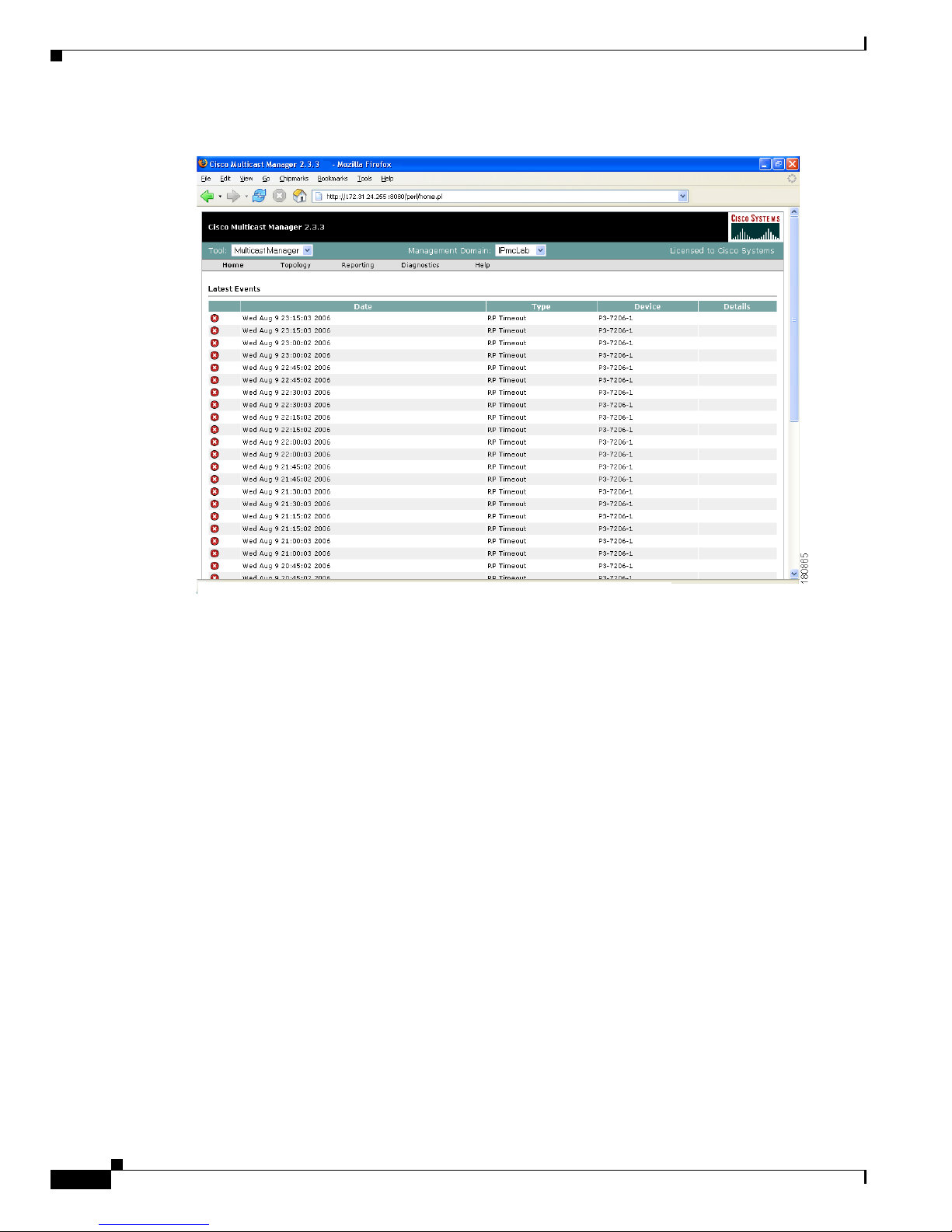
Figure 1-2 Multicast Manager Home Page
For detailed information on this window, see the “Using the Multicast Manager Tool” section on
page 1-43.
CMM 2.3.3 has two main Tools:
• Administration—Perform configuration tasks
• Multicast Manager—View or monitor data
You can find these Tools listed at the top left of the CMM 2.3.3 Web interface.
Using the Administration Tool
System administrators can configure their network using the CMM Administration Tool, containing
these web pages:
• Domain Management, page 1-9
• Discovery, page 1-11
• Admin Utilities, page 1-15
• System Security, page 1-17
• User Management, page 1-18
• Device Configuration, page 1-20
• Global Polling Configuration, page 1-23
• Address Management, page 1-27
• Multicast Manager, page 1-28
Page 19

1-9
User Guide for the Cisco Multicast Manager 2.3.3
OL-7348-01
Chapter 1 Using the Cisco Multicast Manager
Using the Administration Tool
Domain Management
Using Domain Management, you can create and edit domains. A domain is a collection of multicast
routers. Multiple domains may exist, and routers can belong to multiple domains.
The first step in using the CMM is to create a domain:
Step 1 From the Multicast Manager Home page, select the Administration tool.
Step 2 Click on Domain Management.
Step 3 Click on add a new domain. The System Configuration page appears.
Step 4 Complete the fields in the System Configuration page (see field descriptions below) and click Save to
continue and create the new domain. Click Cancel to exit without creating a domain.
The System Configuration page contains:
Field Description
Management Domain A management domain is defined as a contiguous
group of PIM neighbors sharing the same SNMP
community string.
Default Read Only SNMP read-only community string.
Default Read Write SNMP read-write community string. This is
required for retrieving and validating device
configurations.
SNMP Timeout Retry period if node does not respond. Default
value is 0.8.
SNMP Retries Number of retries to contact a node before issuing
a timeout. Default value is 2.
TFTP Server TFTP server IP address. Default is the IP address
of the CMM server.
VTY Password The VTY password is required if you want to
issue show commands from the application.
Certain features, such as querying Layer 2
switches, also require this. If TACACS is being
used, then a username and password can be
supplied instead of the VTY password.
Enable Password (Not currently used.)
TACACS/RADIUS Username If you are using TACACS/RADIUS then you can
enter a username here. See VTY Password above.
Note If you enter a TACACS/RADIUS
username and password here, the
application will use these values
regardless of who is currently logged in.
Users can also enter their own username
and password when issuing show
commands.
Page 20

1-10
User Guide for the Cisco Multicast Manager 2.3.3
OL-7348-01
Chapter 1 Using the Cisco Multicast Manager
Using the Administration Tool
TACACS/RADIUS Password If you are using TACACS/RADIUS then you can
enter a password here. See VTY Password above.
Note If you enter a TACACS/RADIUS
username and password here, the
application will use these values
regardless of who is currently logged in.
Users can also enter their own username
and password when issuing show
commands.
Cache TACACS Info If this box is checked, CMM will cache the
TACACS username and password until the
browser is closed. This eliminates having to enter
the username and password each time you issue a
router command from the application.
Resolve Addresses Performs DNS lookups on all sources found. The
DNS name appears alongside the IP address on
the “Show All Groups” screen. If the server is not
configured for DNS, then DO NOT check the box.
If the box is checked, you may receiver a slower
response, due to the fact that the application is
trying to resolve names. This option is not
recommended if your network contains a large
number of S,Gs.
Use SG Cache Some networks contain thousands of S,Gs.
During discovery,CMM caches all the S,Gs found
in the RPs. If this box is checked, CMM reads the
SG cache when showing lists of sources and
groups, rather then retrieving them again from the
RPs in the network. The cache is automatically
refreshed if RPs are being polled as described
later in this document (see the “RP Polling”
section on page 1-28). The cache can also be
refreshed manually by clicking the Refresh
Cache button in the Multicast Diagnostics
window (see the “Show All Groups” section on
page 1-61). This button only appears if you have
the Use SG Cache option selected. It is highly
recommended to use the SG cache option. If there
are no RPs in the domain being discovered, then
the SG cache is created by querying all the devices
that have been discovered, as would be the case in
a PIM Dense-Mode network. In this case, the SG
cache is only updated when you click the Refresh
Cache button.
Field Description
Page 21

1-11
User Guide for the Cisco Multicast Manager 2.3.3
OL-7348-01
Chapter 1 Using the Cisco Multicast Manager
Using the Administration Tool
Discovery
Once you have created a domain, the second step in using the CMM is to discover your network using
one of these choices, found within the Discovery menu:
• Add Router (not supported)
• Adding Layer 2 Switches to Discovery, page 1-11
• Performing Multicast Discovery, page 1-12
• Adding or Re-discovering a Single Device, page 1-14
The discovery process is multicast-specific and only finds devices that are PIM-enabled. CMM builds
a database of all found devices. Discovery adds support for multiple community strings per domain,
along with device-specific SNMP timeout and retries.
Note If any new routers or interfaces are added to the network, run discovery again so that the database is
consistent with the network topology.
A single router may also be added or rediscovered on the network. A router being added must have a
connection to a device that already exists in the database. A router that is being re-discovered is initially
removed from the database, along with any neighbors that exist in the database. The router, and its
neighbors, are then added back into the database. This option would be used if a change on a device has
caused a change in the SNMP ifIndexes.
Note When possible, the snmp ifindex persist command should be used on all devices.
Adding Layer 2 Switches to Discovery
Layer 2 switches are not included in discovery and must be added manually. You can add switches
individually, or you can import a list of switches in a csv file.
To add switches individually, enter the switch name or IP address and the community string, then click
Add.
To import a list of switches:
Step 1 Create a text file by typing:
#import file format switch IP address or switch name
# this line will be skipped
switchA
192.168.1.1
switchC
10.10.10.1
Step 2 Save the file.
Step 3 Within the Administration too, click on Discovery.
Step 4 Click Add L2 Switch. The Multicast Layer 2 Switch Configuration page appears.
Page 22

1-12
User Guide for the Cisco Multicast Manager 2.3.3
OL-7348-01
Chapter 1 Using the Cisco Multicast Manager
Using the Administration Tool
Figure 1-3 Multicast Layer 2 Switch Configuration
Step 5
Click Browse. Open the file you created.
Step 6 Click Import.
Note Sometimes switches are deployed in a network using different SNMP community strings than those used
on the routers. In this case, simply create another domain, with the appropriate SNMP community
strings, and add the switches to this domain.
Performing Multicast Discovery
To perform a new multicast discovery:
Step 1 Within the Administration tool, click on Discovery.
Step 2 Click Multicast. The Multicast Discovery page appears.
Page 23
1-13
User Guide for the Cisco Multicast Manager 2.3.3
OL-7348-01
Chapter 1 Using the Cisco Multicast Manager
Using the Administration Tool
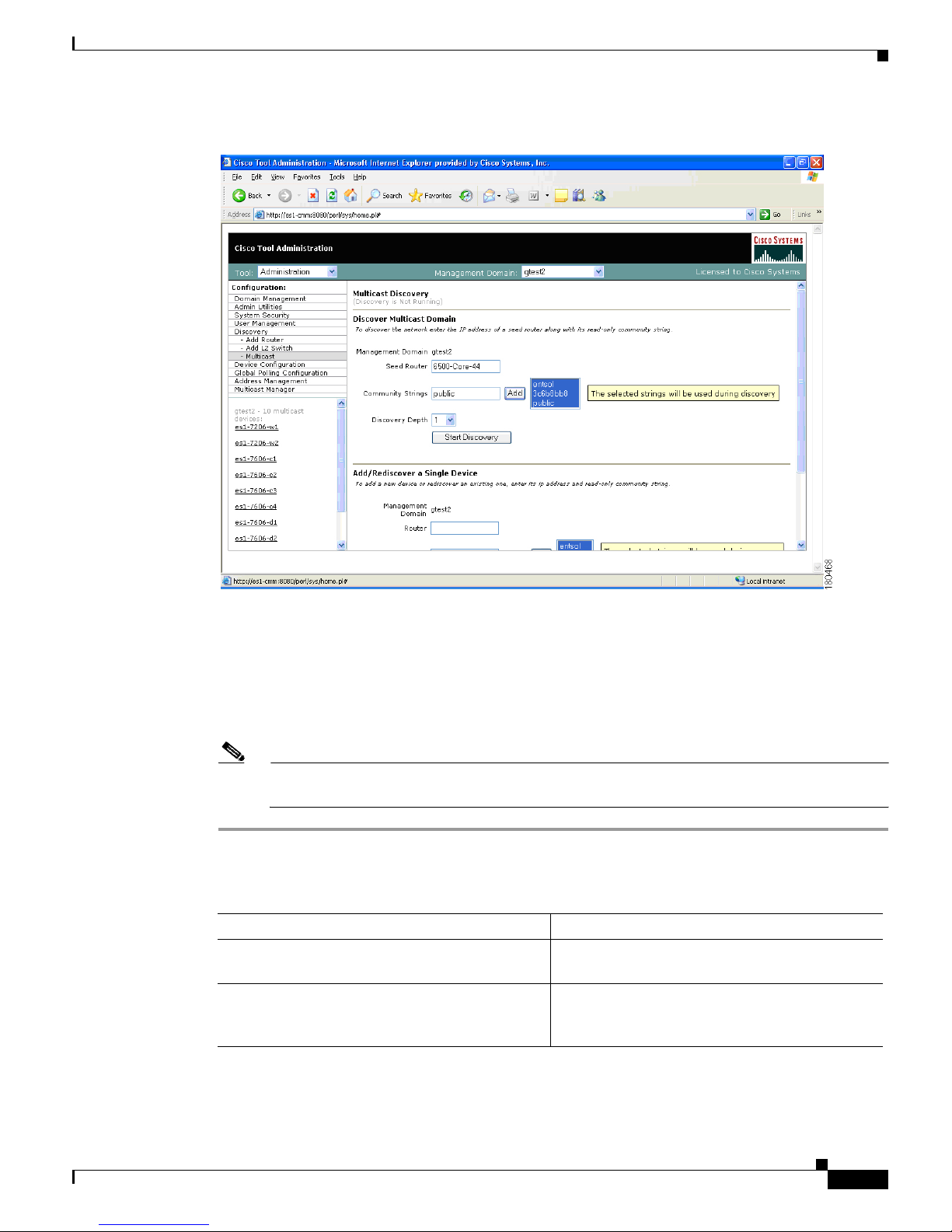
Figure 1-4 Multicast Discovery
Step 3
Next to Management Domain, select the domain you want to discover (only domains that are created
from the System Configuration window appear here). If you select a different domain from the default,
you must complete steps 1 and 2 again.
Step 4 Complete the fields in the Discover Multicast Domain pane (see field descriptions below) and click
Start Discovery to continue. As routers are discovered, they appear in the browser window.
Step 5 (Optional) To view discovery progress as it is running, click Refresh Status.
Note For details on adding or re-discovering a single device, see the “Adding or Re-discovering a
Single Device” section on page 1-14.
The Discover Multicast Domain pane of the Multicast Discovery page contains:
Field Description
Management Domain (Read-only) Lists the selected management
domain.
Seed Router Enter the IP address of the seed router to initiate
discovery from. If you enabled DNS when
configuring the domain, enter a name.
Page 24

1-14
User Guide for the Cisco Multicast Manager 2.3.3
OL-7348-01
Chapter 1 Using the Cisco Multicast Manager
Using the Administration Tool
CMM discovers all routers in the network that are multicast enabled and have interfaces participating in
multicast routing. If the discovery fails to find any routers, or if there are routers in the network that you
expected to discover but did not, check the following:
• Connectivity to the routers
• SNMP community strings on the routers
• Discovery depth setting—is it sufficient
• SNMP ACLs on the routers
When discovery is complete, the browser window displays the time it took to discover the network, and
the number of devices discovered:
Discovery took 15 seconds
Discovered 5 routers
The amount of time the discovery takes depends on the number of routers, number of interfaces, and
router types.
If the discovery seems to stop at a particular router, or seems to pause, check that particular router’s
connectivity to its PIM neighbors. Also, check the PIM neighbor to see if it supports the PIM and
IPMROUTE MIBs. Again, because the discovery is multicast specific, unless these MIBs are supported,
the device will not be included in the database. Issuing the sh snmp mib command on a router gives this
information.
When discovery has finished, you can view the discovered routers in the lower left pane.
Adding or Re-discovering a Single Device
To add or re-discover a single device:
Step 1 Within the Administration tool, click on Discovery.
Step 2 Click Multicast. The Multicast Discovery page appears (see Figure 1-4).
Step 3 Within the Add/Rediscover a Single Device pane, enter the
Step 4 Next to Management Domain, select the domain you want to discover or add to (only domains that are
created from the System Configuration window appear here). If you select a different domain from the
default, you must complete steps 1 and 2 again.
Step 5 Complete the fields in the Add/Rediscover a Single Device pane (see field descriptions below) and click
Add/Rediscover to continue. As devices are discovered, they appear in the browser window.
Community Strings You can add additional community strings if
required.
Discovery Depth Number of PIM neighbors the CMM will discover
from the seed router (similar to a hop count).
Field Description
Page 25
1-15
User Guide for the Cisco Multicast Manager 2.3.3
OL-7348-01
Chapter 1 Using the Cisco Multicast Manager
Using the Administration Tool
The Add/Rediscover a Single Device pane of the Multicast Discovery page contains:
Admin Utilities
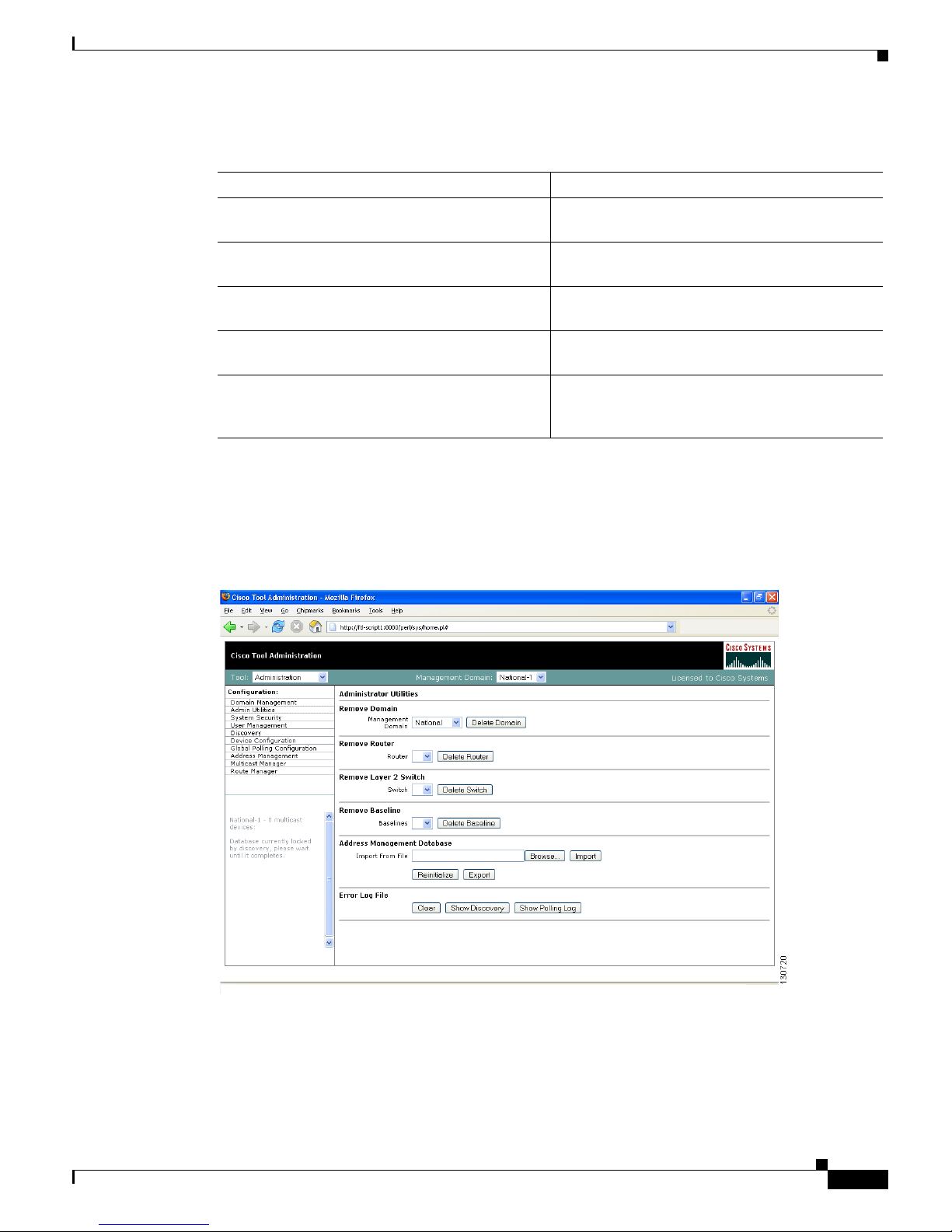
The Administrative Utilities page provides maintenance tools for the system administrator.
Figure 1-5 Administrative Utilities
The Administrative Utilities page contains:
Field Description
Management Domain (Read-only) Lists the selected management
domain.
Router Enter the IP address of the device you want to
discover or add.
Community Strings You can add additional community strings if
required.
This device only Rediscovers this device and updates the current
database with the new information.
One hop from this device Discovers this router and every router within one
hop, and updates the current database with the
new information.
Page 26

1-16
User Guide for the Cisco Multicast Manager 2.3.3
OL-7348-01
Chapter 1 Using the Cisco Multicast Manager
Using the Administration Tool
Field Description
Remove Domain Removes all data associated with a management
domain.
Note Domains cannot be removed while the
polling daemon is running.
Remove Router Removes a specific router from a management
domain. However, if the device is being polled,
you must remove it from the polling configuration
first.
Remove Layer 2 Switch Removes Layer 2 switches from the management
database.
Remove Baseline Removes a forwarding tree baseline, along with
any associated tree change information.
Address Management Database Contains:
• Browse—Find a csv file to import.
• Import—You can import a csv file into the IP
address database. The file should be in the
following format:
#import file format
#this line will be skipped
239.1.1.1,test group
192.168.1.1,sourceA
• Reinitialize—Restores all reserved multicast
addresses to the IP address database.
• Export—Creates a file in /tmp called
mmtIPdb.csv which contains the IP address
database in csv format.
Error Log File Contains:
• Clear—Truncates the error_log file. .
• Show Discovery—Shows discovery-specific
messages contained in the error_log file.
Note The error_log file should be rotated along
with other system log files.
• Show Polling Log—Displays the contents of
the polling log.
Page 27

1-17
User Guide for the Cisco Multicast Manager 2.3.3
OL-7348-01
Chapter 1 Using the Cisco Multicast Manager
Using the Administration Tool
System Security
The System Security page provides TACACS login support for the CMM.
To configure TACACS login, enter the IP address of the TACACS server within the Primary TACACS
Server field.
If the keys are configured incorrectly, they will have to be manually changed in the
/opt/RMSMMT/httpd_perl/conf/httpd.conf file, as follows:
Tacacs_Pri_Key tac_plus_key
Tacacs_Sec_Key tac_plus_key
<Sample AAA Server Config>
group = admins {
service = connection {
priv-lvl=15
}
group = netop {
service = connection {}
}
user = mike {
member = netop
login = des mRm6KucrBaoHY
}
user = admin {
member = admins
login = cleartext "ciscocmm"
}
</Sample AAA Server Config>
Figure 1-6 System Security
Page 28
1-18
User Guide for the Cisco Multicast Manager 2.3.3
OL-7348-01
Chapter 1 Using the Cisco Multicast Manager
Using the Administration Tool
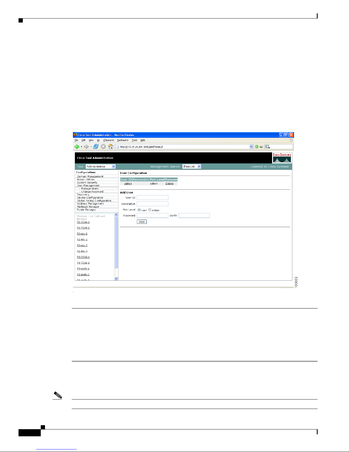
User Management
The CMM provides two privilege levels: user and admin. You need an administrator account to configure
multicast domains, run discovery, create users, create health checks, and use the Admin Utilities
functions.
You can configure users and passwords using the User Management pages:
• Manage Users
• Change Password
Figure 1-7 Manage Users—User Configuration
To add a new user:
Step 1 Enter the user ID.
Step 2 (Optional) Enter a description.
Step 3 Choose the appropriate privilege level, user or admin.
Step 4 Enter the password into the Password and Verify boxes.
Step 5 Click Add.
Clicking on the User ID link in the table allows you to edit the user’s description. Click Delete to delete
a user (only an administrator can delete users).
Note The admin user account cannot be deleted.
Page 29
1-19
User Guide for the Cisco Multicast Manager 2.3.3
OL-7348-01
Chapter 1 Using the Cisco Multicast Manager
Using the Administration Tool
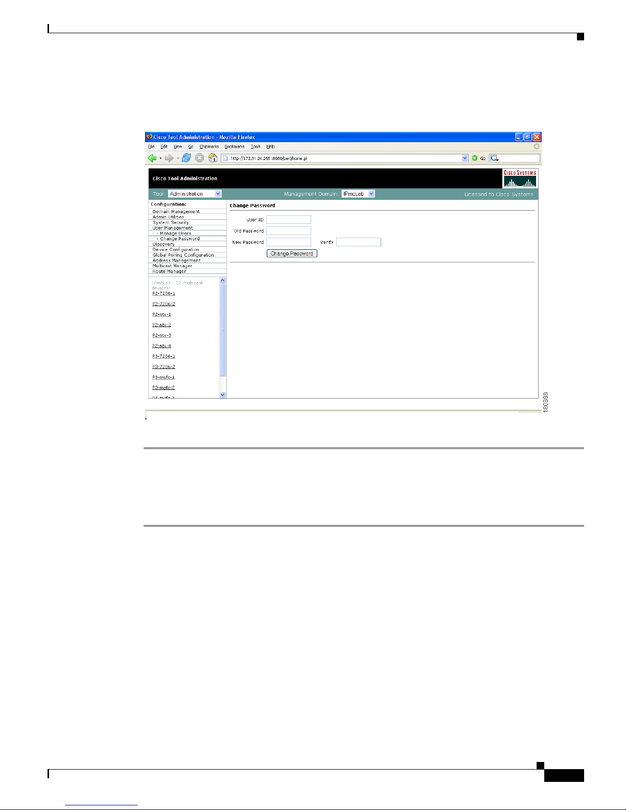
Users can change their password by clicking Change Password.
Figure 1-8 Manage Users—Change Password
To change your password:
Step 1 Enter your user ID.
Step 2 Enter your old password.
Step 3 Enter your new password in the Password and Verify boxes.
Step 4 Click Change Password.
Page 30

1-20
User Guide for the Cisco Multicast Manager 2.3.3
OL-7348-01
Chapter 1 Using the Cisco Multicast Manager
Using the Administration Tool
Device Configuration
Using the Device Configuration page, you can change the SNMP read key of a single device. Select a
Router or Switch, then click Edit Parameters.
Figure 1-9 Device Configuration—Edit Parameters
Downloading Router Configurations
You can download the router configuration for each router in the database to the CMM. Under the Device
Configuration menu at left, click Get All Configs.
If you entered the SNMP write key for the router when you set up the domain, CMM can download and
display configuration files for the router.
Note To use this option, TFTP must be enabled on the server, and the SNMP read-write community string must
be supplied. See the Installation Guide for the Cisco Multicast Manager.
Page 31

1-21
User Guide for the Cisco Multicast Manager 2.3.3
OL-7348-01
Chapter 1 Using the Cisco Multicast Manager
Using the Administration Tool
Figure 1-10 Get All Co nfigs
This process may take some time, depending on the number of routers in the current domain.
Validating Router Configurations
Using the CMM, you can verify if IOS commands exist on a router, either globally, or on a single
interface. Router configurations for a domain are verified against a template. Several sample templates
are included with the application, or you can create a user-defined template, which must be a text (.txt)
file containing a list of IOS commands to check. For example, to check for global commands, start the
text file with the word “global.” To check interface commands as well, add the word “interface” and so
on. You can check for global and interface at the same time, as in the example:
GLOBAL
service timestamps log datetime msec localtime show-timezone
service password-encryption
logging
no logging console
no ip source-route
ip subnet zero
ip classless
INTERFACE
ip pim-sparse-mode
Page 32
1-22
User Guide for the Cisco Multicast Manager 2.3.3
OL-7348-01
Chapter 1 Using the Cisco Multicast Manager
Using the Administration Tool
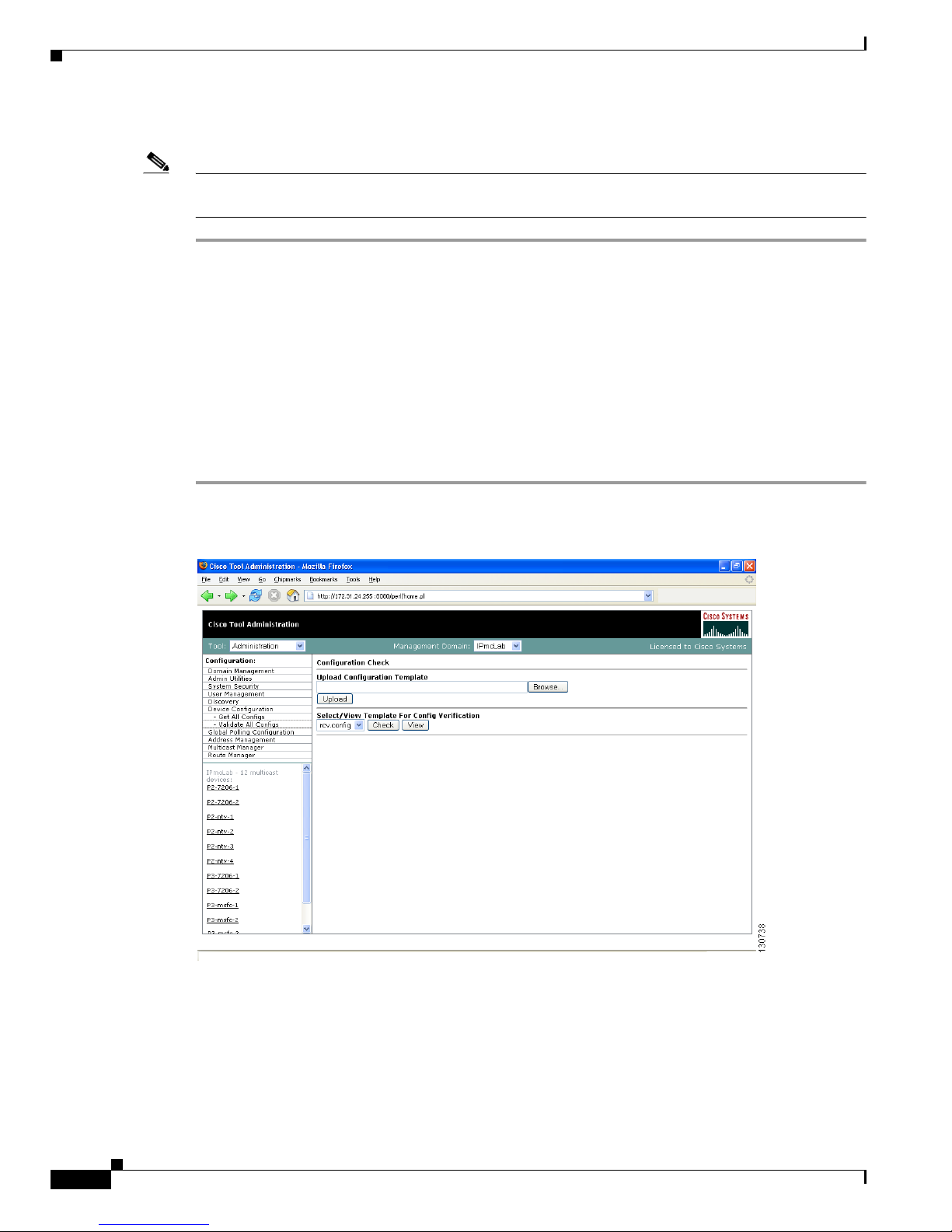
To select a template and initiate validation:
Note Before you can initiate validation, TFTP must be enabled on the server, and the SNMP read-write
community string must be configured in the CMM.
Step 1 Under the Device Configuration menu, click Validate All Configs. The Configuration Check page
opens.
Step 2 Ensure the correct Management Domain is selected.
Step 3 If you want to upload a user-defined template:
a. Click Browse. Open the text (.txt) file you created.
b. Click Upload. The user-defined text file appears in the list below.
Step 4 Select the template you want to use from the list.
Step 5 (Optional) Click View to see the contents of each template.
Step 6 Click Check.
Figure 1-11 Configuration Check
The CMM checks each router in the database for the existence of the commands in the template you
specified. Output looks similar to Figure 1-12.
Page 33

1-23
User Guide for the Cisco Multicast Manager 2.3.3
OL-7348-01
Chapter 1 Using the Cisco Multicast Manager
Using the Administration Tool
Figure 1-12 Configuration Check—Output
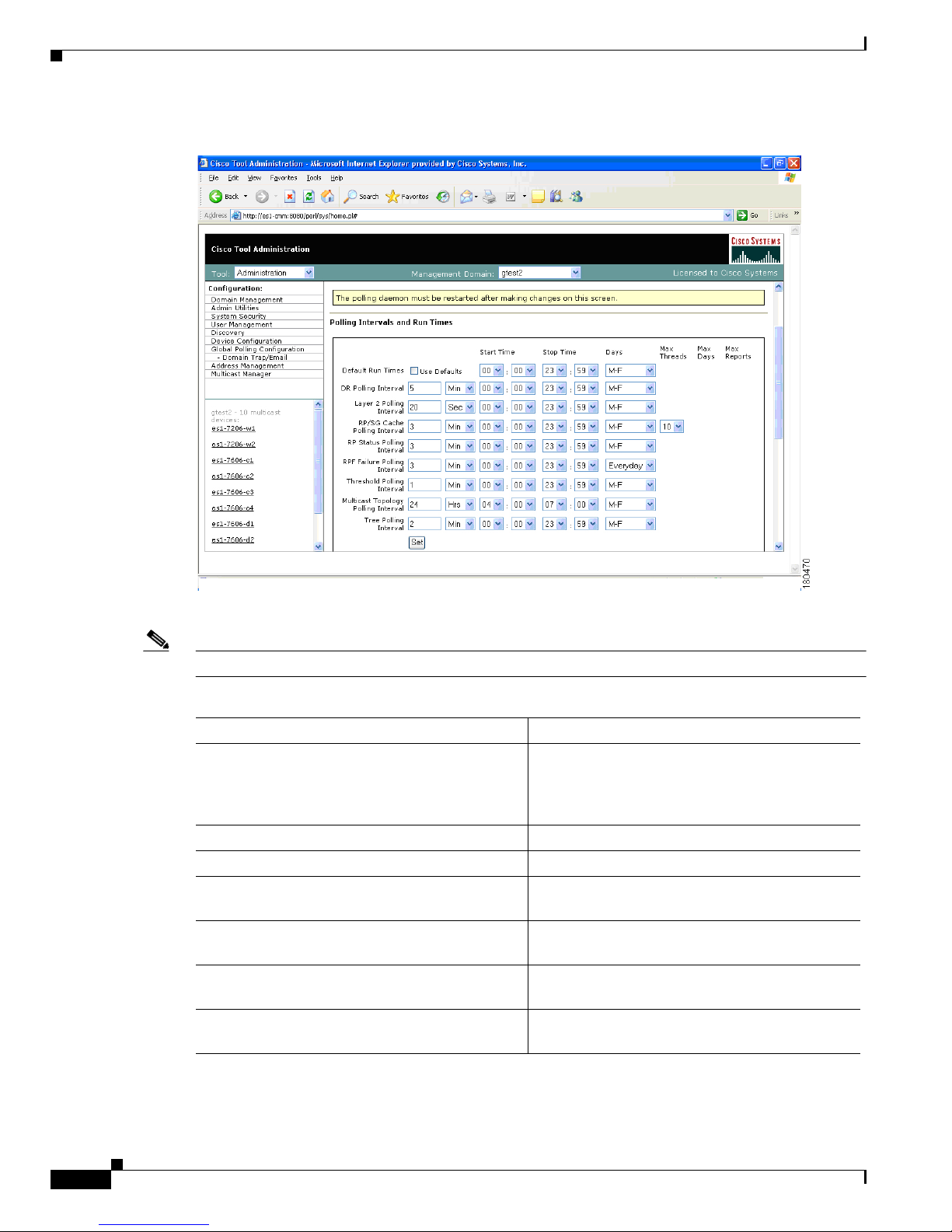
Global Polling Configuration
You can configure each polling element to start and stop at specific times. Each element also has their
own polling intervals. You can configure these values through the Global Polling Configuration page.
Note You must restart the polling daemon after making changes in this page.
Page 34
1-24
User Guide for the Cisco Multicast Manager 2.3.3
OL-7348-01
Chapter 1 Using the Cisco Multicast Manager
Using the Administration Tool
Figure 1-13 Global Polling Configuration
The Global Polling Configuration page contains:
Note Setting any one of these values to be less than 1 disables that specific polling feature.
Field or Button Description
Refresh Status The status line indicates how long the polling
daemon has been running and how it was started.
Click Refresh Status to update the status
information.
Start Starts the polling daemon globally.
Stop Stops the polling daemon globally.
Restart Restarts the polling daemon globally. Each time
you change a polling interval, click Restart.
Default Run Times—Use Defaults Selecting the Use Defaults checkbox sets all the
start/stop times and days to the default values.
DR Polling Interval Checks the status of all DRs in the network. If a
user changes a DR, an SNMP trap is sent.
Layer 2 Polling Interval Amount of time between polling of the Layer 2
ports.
Page 35

1-25
User Guide for the Cisco Multicast Manager 2.3.3
OL-7348-01
Chapter 1 Using the Cisco Multicast Manager
Using the Administration Tool
RP/SG Cache Polling Interval For certain CMM data, such as the data within the
Multicast Diagnostics page (see the “Show All
Groups” section on page 1-61) the CMM queries
each RP, collates a list of active sources, and
groups and displays them. There are 2 ways the
CMM can accomplish this: dynamically when the
command is entered, or the CMM can build a
cache of this information, and when the command
is entered, the cache is queried. Caching is
enabled on the System Configuration page (see
the “Domain Management” section on page 1-9)
and the RP/SG Cache Polling Interval is the time
period that this cache is refreshed.
Deciding whether caching should be turned on
depends upon the number of RPs, sources, and
groups. If the Multicast Diagnostics page takes a
while to display all groups, you may want to turn
caching on.
The Max Threads value controls how many
devices are queried simultaneously. Values can be
1-10. Queries used for RP/SG Cache Polling are
SNMP getbulk queries that can potentially return
large amounts of data. To address timeouts, you
can reduce the number of Max Threads and/or
adjust the SNMP timeout and retry values on the
System Configuration page (see the “Domain
Management” section on page 1-9).
RP Status Polling Interval RP Status Polling queries the sysUpTime of the
RPs configured on the RP Polling Configuration
page (see the “RP Polling” section on page 1-28).
The purpose of this query is to report availability
of the RPs. If the RP responds, an rpReachable
trap is sent. If the RP does not respond, an
rpUnreachable trap is sent. Since at least one of
these traps is sent at each polling interval, you can
also use them to ensure that the polling daemon is
up and running.
RPF Failure Polling Interval Time interval that each router will be polled for
each source and group configured to check the
number of RPF failures.
Threshold Polling Interval Time interval that each router will be polled for
the existence of each source and group
configured, and CMM will ensure that no
thresholds are exceeded.
Field or Button Description
Page 36

1-26
User Guide for the Cisco Multicast Manager 2.3.3
OL-7348-01
Chapter 1 Using the Cisco Multicast Manager
Using the Administration Tool
You can enable or disable the continuous sending of PPS threshold traps using the Enable
Rising/Falling and Normalized Traps for Thresholds section:
• If the Rising/Falling option is not checked (disabled), traps are sent whenever the PPS rate for a
monitored S,G exceeds specified thresholds.
• If the Rising/Falling option is checked (enabled), a trap is sent only when the PPS rate initially
exceeds the high or low threshold. Once the PPS rate returns to the specified range, a normalized
threshold trap is sent.
• Since SNMP v1 traps are sent unreliably, you can set the Trap-Repeat option to allow the initial
and normalized traps to be sent anywhere from 1 to 5 times when an event occurs.
You can add or remove trap receivers using the Configure Global Default SNMP Trap Receivers
section. The SNMP trap receivers specified here are only used if domain-specific SNMP trap receivers
are not specified. Domain-specific trap receivers are specified from the Trap Receiver/Email Polling
Configuration page (see the “Configuring Domain-Specific Trap Receivers and Email Addresses”
section on page 1-26).
You can add or remove Email addresses using the Configure Global Default Email Addresses for Event
Notification section. Email addresses are notified of SSG exceptions and threshold and existence events.
The Email addresses specified here are only used if domain-specific Email addresses are not specified.
Domain-specific Email addresses are specified from the Trap Receiver/Email Polling Configuration
page (see the “Configuring Domain-Specific Trap Receivers and Email Addresses” section on
page 1-26).
Configuring Domain-Specific Trap Receivers and Email Addresses
You can configure the CMM to send domain-specific SNMP trap receivers or emails. Under the Global
Polling Configuration menu at left, click Domain Trap/Email. The Trap Receiver/Email Polling
Configuration page appears.
Multicast Topology Polling Interval Topology polling queries the sysUpTime of each
router in the multicast domain to see if it has been
reloaded. If it has, the polling daemon launches a
Single Router Discovery of that device in the
background, to ensure the SNMP ifIndexes have
not changed.
Tree Polling Interval Time interval that the monitored trees are drawn
and compared with their baselines.
Set Sets the values you enter.
Field or Button Description
Page 37

1-27
User Guide for the Cisco Multicast Manager 2.3.3
OL-7348-01
Chapter 1 Using the Cisco Multicast Manager
Using the Administration Tool
Figure 1-14 Trap Receiver/Email Polling Configuration
You can add or remove trap receivers using the Configure Domain Specific SNMP Trap Receivers
section. The SNMP trap receivers specified here are only used if global SNMP trap receivers are not
specified. Global trap receivers are specified from the Configure Global Default SNMP Trap Receivers
page (see the “Global Polling Configuration” section on page 1-23).
You can add or remove Email addresses using the Configure Domain Specific Email Addresses for
Event Notification section. Email addresses are notified of SSG exceptions and threshold and existence
events. The Email addresses specified here are only used if global Email addresses are not specified.
Global Email addresses are specified from the Configure Global Default SNMP Trap Receivers page (see
the “Global Polling Configuration” section on page 1-23).
Address Management
Using the Address Management page, you can enter multicast group and source addresses into the
database with a description. When the CMM displays these sources and groups, the descriptions will be
added for easy recognition.
The database is pre-populated with all of the reserved address space.
Page 38

1-28
User Guide for the Cisco Multicast Manager 2.3.3
OL-7348-01
Chapter 1 Using the Cisco Multicast Manager
Using the Administration Tool
Figure 1-15 Address Management
Multicast Manager
The Multicast Manager contains:
• RP Polling, page 1-28
• RPF Polling, page 1-32
• SG Polling—Main, page 1-33
• SG Polling—by Device, page 1-36
• L2 Polling, page 1-37
• Tree Polling, page 1-38
• Health Check, page 1-41
RP Polling
Using the RP Polling Configuration page, you can enable the CMM to:
1. Monitor and report all leaves and joins
2. Set a threshold on the number of groups that can join an RP if this is exceeded, a trap is sent
3. Find out if a specific RP is available
4. Create a list of all acceptable sources and groups and send a trap if any rogue sources or groups
appear on the RP
Page 39

1-29
User Guide for the Cisco Multicast Manager 2.3.3
OL-7348-01
Chapter 1 Using the Cisco Multicast Manager
Using the Administration Tool
Note RP availability is configured within the Global Polling Configuration page (see the “Global Polling
Configuration” section on page 1-23). A trap is sent if an RP becomes unavailable, and a report is
generated within the RP Polling Report page (see the “RP Polling Report” section on page 1-49).
Figure 1-16 RP Polling Configuration
The RP Polling Configuration page contains:
Fields and Buttons Description
Refresh Status The status line indicates how long the polling
daemon has been running and how it was started.
Click Refresh Status to update the status
information.
Start Starts the polling daemon globally.
Stop Stops the polling daemon globally.
Restart Restarts the polling daemon globally. Each time
you change a polling interval, click Restart.
Enable RP Group Add Delete Traps Click the checkbox to monitor all leaves and
joins, which are then reported within the RP
Polling Report page (see the “RP Polling Report”
section on page 1-49).
Page 40

1-30
User Guide for the Cisco Multicast Manager 2.3.3
OL-7348-01
Chapter 1 Using the Cisco Multicast Manager
Using the Administration Tool
RP Monitoring To monitor an RP, select the RP from the box.
To monitor a specific number of groups, enter a
number in the Group Limit box.
Click Monitor RP.
If the group limit is exceeded, a report is
generated within the RP Group Threshold Report
page (see the “RP Group Threshold Report”
section on page 1-50).
RPs Being Monitored Lists:
• RP—The name of the RP being monitored
• Group Limit—Number of groups being
monitored for that RP.
• Accept-List—Monitors the sources and
groups active on the RP (see the “RP Accept
List Configuration” section on page 1-31).
• Remove—Deletes the RP.
Single S, G Monitoring Enter the group IP address. If more than one
source becomes active for this group, a report is
generated.
Fields and Buttons Description
Page 41

1-31
User Guide for the Cisco Multicast Manager 2.3.3
OL-7348-01
Chapter 1 Using the Cisco Multicast Manager
Using the Administration Tool
RP Accept List Configuration
The RP Accept List Configuration section lets you monitor the active sources and groups on a specific
RP.
Figure 1-17 RP Accept List Configuration
The RP Accept List Configuration section contains:
Fields and Buttons Description
Source Enter the sources that are allowed to appear on
this RP.
Source Mask Enter the source mask.
Group Enter the groups that are allowed to appear on this
RP.
Group Mask Enter the group mask.
Add/Edit S,G Click to save your changes.
Return to RP Config Click to return to the RP Polling Configuration
page.
Page 42

1-32
User Guide for the Cisco Multicast Manager 2.3.3
OL-7348-01
Chapter 1 Using the Cisco Multicast Manager
Using the Administration Tool
RPF Polling
Using the CMM, you can monitor RPF failures for a particular source and group on any selected router.
If any monitored source and group begins to experience RPF failures that rise above the delta, then
SNMP traps can be sent, and a report generated, which you can view under RPF Failures (see the “RPF
Failures” section on page 1-51).
You can select the source and group from the list, or you can enter them manually. If there are a lot of
sources and/or groups, you can use the filter option, to ensure you are selecting an S,G that actually
exists in the network. The filter option displays only the sources for a selected group, or only the groups
for a selected source. To reset the lists, click Reset S,G Lists.
Figure 1-18 RPF Failure Polling Configuration
The RP Failure Polling Configuration page contains:
Fields and Buttons Description
Refresh Status The status line indicates how long the polling
daemon has been running and how it was started.
Click Refresh Status to update the status
information.
Start Starts the polling daemon globally.
Stop Stops the polling daemon globally.
Restart Restarts the polling daemon globally. Each time
you change a polling interval, click Restart.
Page 43

1-33
User Guide for the Cisco Multicast Manager 2.3.3
OL-7348-01
Chapter 1 Using the Cisco Multicast Manager
Using the Administration Tool
SG Polling—Main
Using the CMM, you can poll sources and groups with high and low thresholds.
You can select the source and group from the list, or you can enter them manually. If there are a lot of
sources and/or groups, you can use the filter option, to ensure you are selecting an S,G that actually
exists in the network. The filter option displays only the sources for a selected group, or only the groups
for a selected source.
Source Enter or select the IP address of the source to
monitor.
Filter Groups Filters the output to contain only the relevant
groups.
Group Enter or select the IP address of the group to
monitor.
Filter Sources Filters the output to contain only the relevant
sources.
Reset SG Lists Clears any entries and refreshes the source and
group lists.
Router Enter the router name.
Delta Number of RPF failures per sampling period that
trigger a report.
Apply Applies and saves the changes.
Refresh Cache Click Refresh Cache to refresh the table of
sources and groups.
Fields and Buttons Description
Page 44

1-34
User Guide for the Cisco Multicast Manager 2.3.3
OL-7348-01
Chapter 1 Using the Cisco Multicast Manager
Using the Administration Tool
Figure 1-19 SG Polling Configuration
The SG Polling Configuration page contains:
Fields and Buttons Description
Refresh Status The status line indicates how long the polling
daemon has been running and how it was started.
Click Refresh Status to update the status
information.
Start Starts the polling daemon globally.
Stop Stops the polling daemon globally.
Restart Restarts the polling daemon globally. Each time
you change a polling interval, click Restart.
Source Enter or select the IP address of the source to
monitor.
Filter Groups Filters the output to contain only the relevant
groups.
Group Enter or select the IP address of the group to
monitor.
Filter Sources Filters the output to contain only the relevant
sources.
Reset SG Lists Clears any entries and refreshes the source and
group lists.
Select Routers Enter the router name.
Page 45

1-35
User Guide for the Cisco Multicast Manager 2.3.3
OL-7348-01
Chapter 1 Using the Cisco Multicast Manager
Using the Administration Tool
Current Source/Group Polling Configuration
The Current Source/Group Polling Configuration section displays all the sources and groups you are
currently monitoring.
Figure 1-20 Current Source/Group Polling Configuration
Units Select either packets per sampling period (pps) or
bits per sampling period (bps).
High Threshold Enter the high threshold that, if exceeded,
generates a report.
Low Threshold Enter the low threshold that, if exceeded,
generates a report.
Apply Applies and saves the changes.
Refresh Cache If you are using S,G caching, the cache contents
appear. Click Refresh Cache to refresh the table
of sources and groups.
Display Filter Options You can filter the list of monitored sources and
groups by limiting to source, group, and/or router.
Display Configured SGs Displays all the sources and groups you are
currently monitoring (see the “Current
Source/Group Polling Configuration” section on
page 1-35).
Fields and Buttons Description
Page 46

1-36
User Guide for the Cisco Multicast Manager 2.3.3
OL-7348-01
Chapter 1 Using the Cisco Multicast Manager
Using the Administration Tool
The Current Source/Group Polling Configuration section shows you all monitored sources and
groups in a tabular format.
• Under the Modify column, you can edit or delete a specific source and group.
• Under the Time Threshold column, click on Time-Based Thresholds to configure up to 50
different time of day high and low thresholds for each source and group. Click the Set Thresholds
button to save your changes.
Each time a source and group exceeds a threshold, a trap is sent and a report is generated.
SG Polling—by Device
You can select a particular router using the The Device SG Polling Configuration page, and you can
configure which sources and routers to monitor on the specific device.
Figure 1-21 Device SG Polling Configuration
The Device SG Polling Configuration page contains:
Fields and Buttons Description
Refresh Status The status line indicates how long the polling
daemon has been running and how it was started.
Click Refresh Status to update the status
information.
Start Starts the polling daemon globally.
Stop Stops the polling daemon globally.
Page 47
1-37
User Guide for the Cisco Multicast Manager 2.3.3
OL-7348-01
Chapter 1 Using the Cisco Multicast Manager
Using the Administration Tool
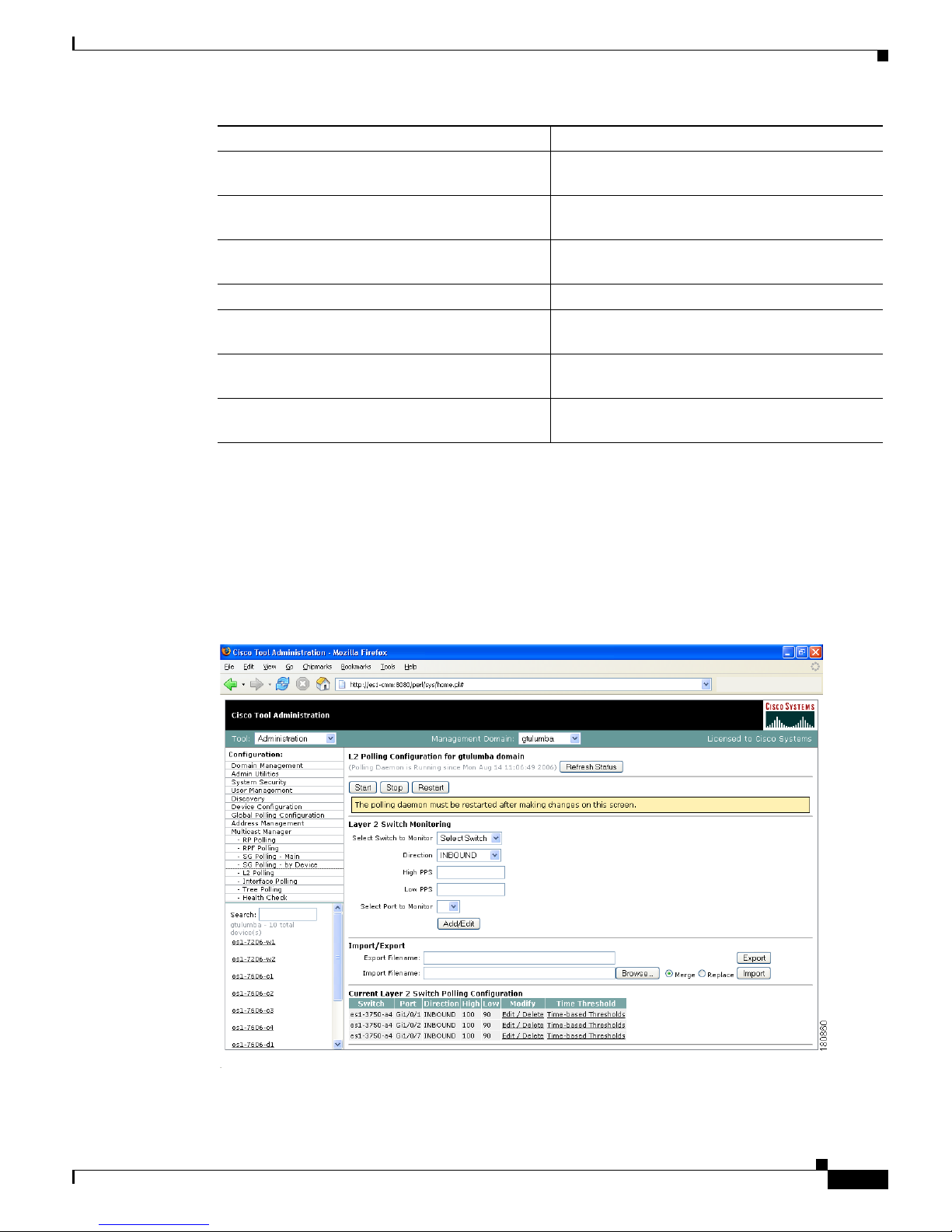
L2 Polling
You can add Layer 2 switches to the CMM individually, or you can import a list (see the “Adding Layer
2 Switches to Discovery” section on page 1-11). The CMM can monitor the total number of multicast
packets inbound and/or outbound from any Layer 2 port.
You can also configure up to 50 different time of day thresholds for each port.
Figure 1-22 L2 Polling Configuration
Restart Restarts the polling daemon globally. Each time
you change a polling interval, click Restart.
Group Filter Regexp Enter any part of the multicast address. Only those
that match appear.
Refresh Clears the Group Filter Regexp previously
entered.
Router Select the router name.
Units Select either packets per sampling period (pps) or
bits per sampling period (bps).
High Threshold Enter the high threshold that, if exceeded,
generates a report.
Low Threshold Enter the low threshold that, if exceeded,
generates a report.
Fields and Buttons Description
Page 48

1-38
User Guide for the Cisco Multicast Manager 2.3.3
OL-7348-01
Chapter 1 Using the Cisco Multicast Manager
Using the Administration Tool
The L2 Polling Configuration page contains:
The Current Layer 2 Switch Polling Configuration section shows you all monitored switches and
ports in a tabular format.
• Under the Modify column, you can edit or delete a specific switch and port.
• Under the Time Threshold column, click on Time-Based Thresholds to configure up to 50
different time of day high and low thresholds for each port. Click the Set Thresholds button to save
your changes.
Each time a port exceeds a threshold, a trap is sent and a report is generated.
Tree Polling
Before you can monitor a tree using the Tree Polling Configuration page, you must build a multicast tree
and save it to the database as a baseline (see the “Show All Groups” section on page 1-61).
Once saved, the trees appear in the Saved Trees list of the Tree Polling Configuration page. To monitor
a tree, select the tree name, and click Add. The tree is drawn in the background for every interval that
you set up for tree polling (see the Global Polling Configuration, page 1-23). This tree is compared with
the tree saved in the database. If it is different, a trap is sent, and a report generated.
Fields and Buttons Description
Refresh Status The status line indicates how long the polling
daemon has been running and how it was started.
Click Refresh Status to update the status
information.
Start Starts the polling daemon globally.
Stop Stops the polling daemon globally.
Restart Restarts the polling daemon globally. Each time
you change a polling interval, click Restart.
Select Switch to Monitor Select the name or IP address of the switch you
want to monitor.
Direction Select either inbound packets received at this port,
or outbound packets sent from this port.
High PPS Enter the high threshold that, if exceeded,
generates a report.
Low PPS Enter the low threshold that, if exceeded,
generates a report.
Select Port to Monitor Select the port to monitor. Ports appear in the
following format: ifIndex:module/port.
Add/Edit Add the port you want to monitor, or from the list
of ports, select edit to edit that entry.
Page 49

1-39
User Guide for the Cisco Multicast Manager 2.3.3
OL-7348-01
Chapter 1 Using the Cisco Multicast Manager
Using the Administration Tool
Figure 1-23 Tree Polling Configuration
The Tree Polling Configuration page contains:
Fields and Buttons Description
Refresh Status The status line indicates how long the polling
daemon has been running and how it was started.
Click Refresh Status to update the status
information.
Start Starts the polling daemon globally.
Stop Stops the polling daemon globally.
Restart Restarts the polling daemon globally. Each time
you change a polling interval, click Restart.
Saved Trees Lists all the multicast tree baselines that have
been saved.
Add Adds the selected tree for monitoring.
Page 50

1-40
User Guide for the Cisco Multicast Manager 2.3.3
OL-7348-01
Chapter 1 Using the Cisco Multicast Manager
Using the Administration Tool
Trees to be Polled
Using the Trees to be Polled table, you can:
• View tree details and topology by clicking on a tree name under Baseline
• Monitor for S,G (PPS) when a tree is polled, and generate SNMP traps for Max Delta deviations by
clicking on Configure under Monitor PPS.
Figure 1-24 Tree Polling Configuration—Configure
•
Select a router(s) and specify a value in Max Delta Between PPS Samples, then click Set. To
remove a router from monitoring, select the router and click Remove. You can also return to the
main Tree Polling Configuration page.
Note You can select multiple routers by holding down the Ctrl key.
• Remove a tree by clicking on Delete under Remove
Page 51
1-41
User Guide for the Cisco Multicast Manager 2.3.3
OL-7348-01
Chapter 1 Using the Cisco Multicast Manager
Using the Administration Tool
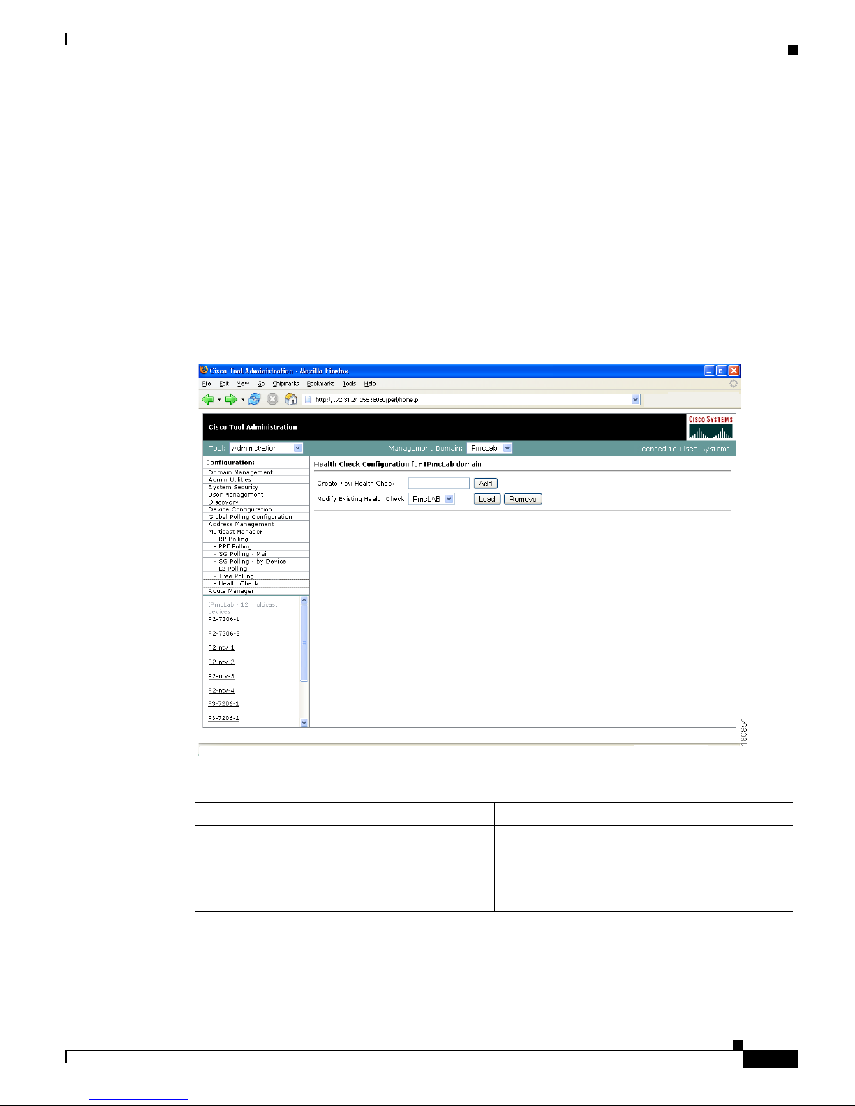
Health Check
Health checks give you an immediate status update on several key multicast network indicators,
including:
• Status of selected RPs
• MSDP status
• Existence of S,G entries on selected routers
• Status of multicast forwarding trees
You can create several health checks. Health checks run dynamically, meaning they must be
user-initiated.
Figure 1-25 Health Check Configuration
The Health Check page contains:
Fields and Buttons Description
Create New Health Check Type a name for the health check.
Add Adds a new named health check.
Modify Existing Health Check Select the named health check you want to
modify.
Page 52

1-42
User Guide for the Cisco Multicast Manager 2.3.3
OL-7348-01
Chapter 1 Using the Cisco Multicast Manager
Using the Administration Tool
Modifying Health Checks
The Health Check Configuration—Modification section lets you modify a selected health check.
Figure 1-26 Health Check Configuration—Modification
You can also check MSDP peering of the selected router by clicking Configure within the RPs Being
Checked table.
Load Loads an existing named health check for
modification (see the “Modifying Health Checks”
section on page 1-42).
Remove Deletes the health check selected in the Modify
Existing Health Check box.
Fields and Buttons Description
Page 53

1-43
User Guide for the Cisco Multicast Manager 2.3.3
OL-7348-01
Chapter 1 Using the Cisco Multicast Manager
Using the Multicast Manager Tool
Figure 1-27 Health Check Configuration—Peers
Select the peers you want to check, then click Set. You are returned to the Health Check Configuration
Modification page. Select the sources, groups and routers to check. To check the status of multicast trees,
select the baseline under Forwarding Trees and click Add.
To run the actual health check, see the “Health Check” section on page 1-73.
Using the Multicast Manager Tool
You can view or monitor data using the CMM Multicast Manager Tool, containing these web pages:
• Home, page 1-44
• Topology, page 1-44
• Reporting, page 1-48
• Diagnostics, page 1-60
• Help, page 1-79
Page 54

1-44
User Guide for the Cisco Multicast Manager 2.3.3
OL-7348-01
Chapter 1 Using the Cisco Multicast Manager
Using the Multicast Manager Tool
Home
The Home page shows the last 20 events (see the “Latest Events” section on page 1-49).
Figure 1-28 Multicast Manager Home Page
Topology
Using Top o lo g y, you can display routers and their multicast information in the database, on an individual
basis, or by showing the complete database.
To see the complete database, click Display All. Router names appear at the top of each table.
Page 55

1-45
User Guide for the Cisco Multicast Manager 2.3.3
OL-7348-01
Chapter 1 Using the Cisco Multicast Manager
Using the Multicast Manager Tool
Figure 1-29 Topology Display All
The Topology Display All page contains:
To see topology for an individual router, click a router from the list pane at lower left.
Field Description
Local Int Interfaces running multicast.
Local IP IP address of the interfaces.
PIM Mode PIM Mode, can be sparse or dense.
IGMP IGMP version.
Neighbor PIM neighbor name.
Neighbor’s INT PIM neighbor’s interface.
Neighbor IP PIM neighbor’s IP address.
PIM Mode PIM neighbor's mode, can be sparse or dense.
IGMP IGMP version of PIM neighbor.
DR DR information.
Page 56

1-46
User Guide for the Cisco Multicast Manager 2.3.3
OL-7348-01
Chapter 1 Using the Cisco Multicast Manager
Using the Multicast Manager Tool
Figure 1-30 Topology for an Individual Router
The Topology for an Individual Router page contains:
Note For details on the table columns within this window, see the descriptions for the Topology Display All
window.
To see a topological display of the routers, click on PIM Neighbors.
Field or Button Description
Username Enter your username.
Password Enter your password.
Show Command Enter any show commands on the router.
Show Click Show to run the selected command.
PIM Neighbors PIM neighbor name.
Page 57

1-47
User Guide for the Cisco Multicast Manager 2.3.3
OL-7348-01
Chapter 1 Using the Cisco Multicast Manager
Using the Multicast Manager Tool
Figure 1-31 PIM Neighbors
On the PIM Neighbors page:
• Green = Router that was selected and its local interfaces
• Purple = PIM neighbor’s interfaces of this router’s PIM neighbors
• Blue = Names of the PIM neighbors of the selected router
Page 58

1-48
User Guide for the Cisco Multicast Manager 2.3.3
OL-7348-01
Chapter 1 Using the Cisco Multicast Manager
Using the Multicast Manager Tool
Reporting
With the Reporting tool, you can view:
• A record of the latest SNMP traps sent
• Historical graphs or trends
• Routers in the database IOS versions
The following options are available under reporting:
• Latest Events, page 1-49
• RP Polling Report, page 1-49
• RP Group Threshold Report, page 1-50
• RPF Failures, page 1-51
• Group Gone Report, page 1-52
• S,G Threshold Report, page 1-52
• Layer 2 PPS Threshold Report, page 1-53
• SSG Report, page 1-54
• Tree Report, page 1-55
• S,G Delta Report, page 1-57
• Historical Graphs, page 1-58
• Display All IOS Versions, page 1-60
Note The information shown for each type of report, with the exception of Historical Graphs, only spans the
previous 24 hours. There may be more information available in the log file. However, it is recommended
that the events.log file be rotated every 24 to 48 hours, depending on event activity.
Page 59

1-49
User Guide for the Cisco Multicast Manager 2.3.3
OL-7348-01
Chapter 1 Using the Cisco Multicast Manager
Using the Multicast Manager Tool
Latest Events
Using the Latest Events page, you can set a configurable amount of the latest events generated by the
CMM. Clicking Report lists the traps in time order.
Figure 1-32 Latest Events
RP Polling Report
Using the RP Polling Report, you can monitor:
• All leaves and joins for the selected RP (if the Enable RP Add/Delete Traps option is selected, see
the “RP Polling” section on page 1-28).
• If the selected RP becomes unavailable
• Any rogue source or group that joins the selected RP
To generate an RP Polling report:
Step 1 Select an RP from the list.
Step 2 You can specify the maximum number of events to display.
Step 3 Click Report. The report contains any events that have occurred in the last 24 hours.
Page 60
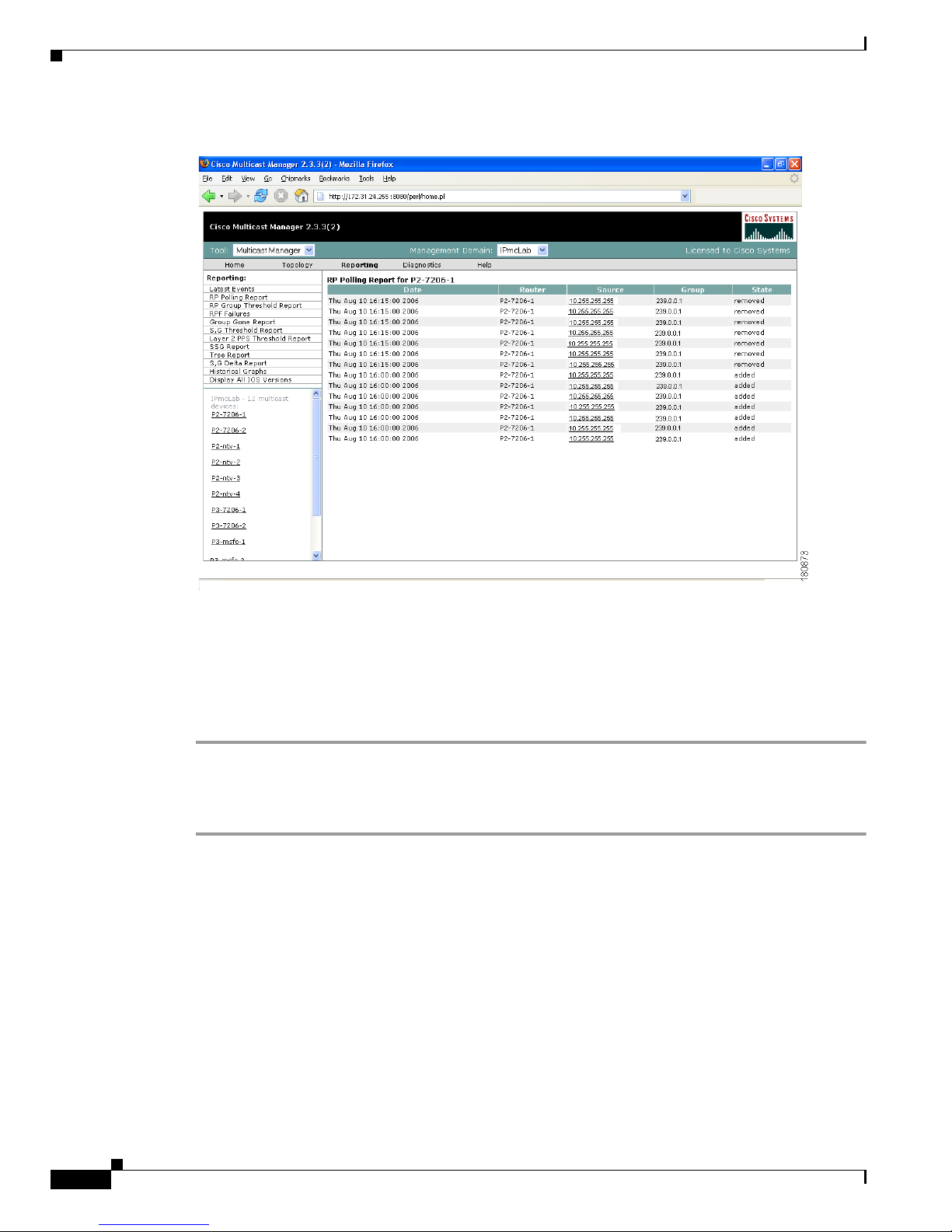
1-50
User Guide for the Cisco Multicast Manager 2.3.3
OL-7348-01
Chapter 1 Using the Cisco Multicast Manager
Using the Multicast Manager Tool
Figure 1-33 RP Polling Report
RP Group Threshold Report
Using the RP Group Threshold Report, you can monitor a list of RPs that have exceeded their active
number of groups limit.
To generate an RP Group Threshold report:
Step 1 Select an RP from the list.
Step 2 You can specify the maximum number of events to display.
Step 3 Click Report. The report contains any events that have occurred in the last 24 hours.
Page 61

1-51
User Guide for the Cisco Multicast Manager 2.3.3
OL-7348-01
Chapter 1 Using the Cisco Multicast Manager
Using the Multicast Manager Tool
Figure 1-34 RP Group Threshold Polling Report
RPF Failures
Using the RPF Failures Report, you can monitor all routers that are experiencing RPF failures above
the configured threshold for the configured sources and groups.
To generate an RPF Failures report:
Step 1 Select an RP from the list.
Step 2 You can specify the maximum number of events to display.
Step 3 Click Report. The report contains any events that have occurred in the last 24 hours.
Page 62

1-52
User Guide for the Cisco Multicast Manager 2.3.3
OL-7348-01
Chapter 1 Using the Cisco Multicast Manager
Using the Multicast Manager Tool
Figure 1-35 RPF Failures Report
Group Gone Report
The Group Gone Report is currently unsupported. Functionality in this page has moved to the S,G
Polling Report.
S,G Threshold Report
Using the S,G Threshold Report, you can monitor every source and group that has exceeded its
configured threshold.
To generate an S,G Threshold report:
Step 1 Select a Group from the list.
Step 2 You can specify the maximum number of events to display.
Step 3 Click Report. The report contains any events that have occurred in the last 24 hours, and contains pps
and bps.
Page 63

1-53
User Guide for the Cisco Multicast Manager 2.3.3
OL-7348-01
Chapter 1 Using the Cisco Multicast Manager
Using the Multicast Manager Tool
Figure 1-36 S,G Threshold Report
Layer 2 PPS Threshold Report
Using the Layer 2 PPS Threshold Report, you can monitor all Layer 2 ports that have exceeded their
configured thresholds.
To generate a Layer 2 PPS Threshold Report:
Step 1 Select a switch from the list.
Step 2 Select a port from the list.
Step 3 Click Select. The report contains any events that have occurred in the last 24 hours.
Note The report is for inbound and outbound traffic on the port.
Page 64

1-54
User Guide for the Cisco Multicast Manager 2.3.3
OL-7348-01
Chapter 1 Using the Cisco Multicast Manager
Using the Multicast Manager Tool
Figure 1-37 Layer 2 PPS Threshold Report
SSG Report
Using the SSG Report, you can display information about groups that have more than one sender.
To generate an SSG Report:
Step 1 Enter the multicast group address.
Step 2 Click Report. The report contains any events that have occurred in the last 24 hours. The count indicates
the number of sources sending to the group.
Page 65

1-55
User Guide for the Cisco Multicast Manager 2.3.3
OL-7348-01
Chapter 1 Using the Cisco Multicast Manager
Using the Multicast Manager Tool
Figure 1-38 SSG Report
Tree Report
Using the Multicast Tree Report, you can draw and save multicast trees (called baselines). You can then
set up the CMM to draw trees that have been saved in the background, and report any changes (only
changes to Layer 3 devices are reported).
Note The drawing and saving of trees is covered in the “Show All Groups” section on page 1-61.
If a multicast tree you are monitoring changes, a trap is generated. You can then view the baseline and
the changed tree. Changes are highlighted in the text and also in the drawing.
To generate a Multicast Tree Report:
Step 1 Select a baseline (multicast tree) from the list.
Step 2 You can specify the maximum number of events to display.
Step 3 Click Select. The report contains any events that have occurred in the last 24 hours.
Page 66
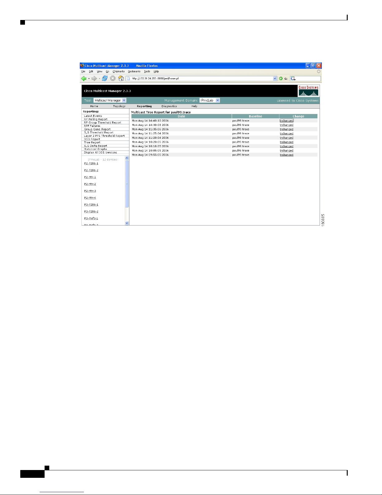
1-56
User Guide for the Cisco Multicast Manager 2.3.3
OL-7348-01
Chapter 1 Using the Cisco Multicast Manager
Using the Multicast Manager Tool
Figure 1-39 Tree Report
Clicking “trchanged” in the third column in the report will graphically show the baseline, along with the
changed tree. Changes to the tree are highlighted in the table at the top as shown in the figure. The
baseline and the current tree are also shown graphically.
Page 67

1-57
User Guide for the Cisco Multicast Manager 2.3.3
OL-7348-01
Chapter 1 Using the Cisco Multicast Manager
Using the Multicast Manager Tool
Figure 1-40 Tree Report Page—Trchanged
S,G Delta Report
Using the Multicast S,G Delta Report, you can view information about PPS rate deviation on multicast
trees.
To generate a Multicast S,G Delta Report:
Step 1 Select a baseline (multicast tree) from the list.
Step 2 You can specify the maximum number of events to display.
Step 3 Click Select. The report contains any events that have occurred in the last 24 hours.
Page 68

1-58
User Guide for the Cisco Multicast Manager 2.3.3
OL-7348-01
Chapter 1 Using the Cisco Multicast Manager
Using the Multicast Manager Tool
Figure 1-41 Multicast S,G Delta Report
Historical Graphs
Using Historical Graphs, you can view historical data in a graph format. Historical data is collected
when you start to monitor:
• Source and group activity in a router
or
• multicast packets inbound or outbound of a Layer 2 port
or
• source and group packet deviations on baseline multicast trees.
To view Historical Graphs:
Step 1 Select a Graph Type from the list:
• SG Delta PPS
• SG PPS
• SG BPS
• Switch Port PPS
Page 69

1-59
User Guide for the Cisco Multicast Manager 2.3.3
OL-7348-01
Chapter 1 Using the Cisco Multicast Manager
Using the Multicast Manager Tool
Step 2 Select a Time Range:
• User Specified
• Hour
• Day
• Wee k
• Month
Then select a Start and End range.
Step 3 A list of available reports appears. Highlight the appropriate report(s) and click Display. You can select
up to 3 reports to display on the graph. Data stored for trending purposes is kept for up to 18 months.
Note Data must be collected to generate a report. If you have selected the correct Graph Type, and you do not
see any entries, ensure that data is being collected (see the “Top Talkers” section on page 1-75).
Figure 1-42 Historical Graphs
Page 70

1-60
User Guide for the Cisco Multicast Manager 2.3.3
OL-7348-01
Chapter 1 Using the Cisco Multicast Manager
Using the Multicast Manager Tool
Display All IOS Versions
Using the IOS Version Info page, you can view the IOS version of all discovered routers in the current
domain. You can sort the table by device, IP address, IOS version, or model by clicking on the
corresponding column heading.
Figure 1-43 IOS Version Info
Diagnostics
The Diagnostics tool gives you a global view and a router-specific view of your network. The following
sections describe global diagnostics:
• Show All Groups, page 1-61
• Locate Host, page 1-66
• Network Status, page 1-67
• RP Status, page 1-68
• RP Summary, page 1-69
• IGMP Diagnostics, page 1-69
• MSDP Status, page 1-70
• Layer 2 Switches, page 1-71
Page 71

1-61
User Guide for the Cisco Multicast Manager 2.3.3
OL-7348-01
Chapter 1 Using the Cisco Multicast Manager
Using the Multicast Manager Tool
• Health Check, page 1-73
• 6500 Troubleshooting, page 1-73
• Top Talkers, page 1-75
The following section describes router-specific diagnostics:
• Router Diagnostics, page 1-77
Show All Groups
With the Show All Groups page, you can:
1. View all of the active sources and groups in the network in tabular format. Groups are listed in
numerical order, and the number of sources for each group appears in the last column. If there is
more than one source for a group, click Sources to view them all.
2. Draw complete graphical trees by clicking on a group.
3. Draw filtered graphical trees by selecting the Source, Group, FHR and LHR.
4. Plot the pps/bps for a particular source and group.
Figure 1-44 Multicast Diagnostics
(Optional) If you are using S,G caching, the cache contents appear. Click Refresh Cache to refresh the
table of sources and groups.
If there are a lot of sources and groups present, you can filter the display to show only those you are
interested in:
• Source—Enter or select the IP address of the source to monitor.
Page 72

1-62
User Guide for the Cisco Multicast Manager 2.3.3
OL-7348-01
Chapter 1 Using the Cisco Multicast Manager
Using the Multicast Manager Tool
• Filter Groups—Filters the output to contain only the relevant groups.
• Group—Enter or select the IP address of the group to monitor.
• Filter Sources—Filters the output to contain only the relevant sources.
• Reset SG Lists—Clears any entries and refreshes the source and group lists.
To ensure a source is sending data, you can plot traffic over a period of time:
• Select Router—Select the router to take the sample from.
• Samples—Enter the number of samples (1-50).
Note If the device is a 6500, you may need to adjust the sampling period in order to generate useful
data.
• Interval—Enter the interval between samples (1-90s).
• Graph—Select the type of graph, line or bar.
• Val ue —Select the value, bps or pps.
• Click Plot. This produces a graph for the currently selected S,G on the selected router. You can also
save this graph on the server.
Note This option is not meant for long term polling, but rather as an immediate troubleshooting tool.
For long term polling of PPS data, the S,G should be configured under S,G Threshold polling.
Figure 1-45 Multicast Diagnostics—Plotting Traffic
Page 73

1-63
User Guide for the Cisco Multicast Manager 2.3.3
OL-7348-01
Chapter 1 Using the Cisco Multicast Manager
Using the Multicast Manager Tool
To draw a graphical tree between two particular routers:
• FHR—Select the first hop router that the trace should start under.
• LHR—Select the last hop router that the trace should end under.
• Click Tra c e . The CMM draws a tree of the source and group selected from the router in FHR to the
router in LHR.
View the list of active sources and groups:
• Group—Lists all active groups. To draw a multicast tree, click on a group. A new page appears with
the multicast tree in tabular and graphical format. Routers known as RPs to the source router appear
green.
Note If there is more than one source for the group, click on Sources under Number of Sources and
select the source you want to draw the tree from.
Figure 1-46 Drawing a Multicast Tree (Baseline)
•
To save the multicast tree as a baseline, enter a name within Tr a ce Fi l e , and click Save As. The
window closes. You can use the saved baseline for tree polling (see the “Tree Polling” section on
page 1-38).
Note You can also save the tree as a .jpeg, .bmp, or .png file by right-clicking on it.
Page 74

1-64
User Guide for the Cisco Multicast Manager 2.3.3
OL-7348-01
Chapter 1 Using the Cisco Multicast Manager
Using the Multicast Manager Tool
Figure 1-47 Viewing IP Multicast Routing Information
• (Optional) Clicking on a router in the multicast tree opens another page that contains IP multicast
routing information for the S,G that has been traced:
–
Show Command—Enter any show commands on the router. A new window opens that contains
multicast route information for the selected router.
–
Username—Enter your username.
–
Password—Enter your password.
–
MIB
–
Val ue
–
Description
Page 75

1-65
User Guide for the Cisco Multicast Manager 2.3.3
OL-7348-01
Chapter 1 Using the Cisco Multicast Manager
Using the Multicast Manager Tool
Figure 1-48 Multicast Diagnostics
• Group (DNS)—Name given to this group in DNS.
• Group (DB)—Name given to this group in the address database.
• Source IP—IP address of the source.
• Source (DNS)—Name given to this source in DNS.
Note The Source (DNS) field is populated only if DNS is configured, and if Resolve Sources is
selected on the Device Configuration page. It should be noted that resolving thousands of
addresses via DNS can be extremely slow.
• Source (DB)—Name given to this source in the address database.
• Number of Sources—Number of sources in this group.
• To view previously saved source bps/pps files, select the file, and click Display.
• To view previously saved traces, select the trace, and click Display.t5rrrrrrrrrrrrrrrru7
Page 76

1-66
User Guide for the Cisco Multicast Manager 2.3.3
OL-7348-01
Chapter 1 Using the Cisco Multicast Manager
Using the Multicast Manager Tool
Locate Host
Using the Locate Host page, you can find sources and receivers in the network. Enter the IP Address or
hostname (if DNS is configured) and click Locate.
Figure 1-49 Locate Host
Page 77

1-67
User Guide for the Cisco Multicast Manager 2.3.3
OL-7348-01
Chapter 1 Using the Cisco Multicast Manager
Using the Multicast Manager Tool
Network Status
Using the Network Status page, you can view the status of all devices in the current multicast domain.
The System Up Time appears for all devices that are up. Devices that are down or unreachable appear in
red.
Figure 1-50 Network Status
Page 78

1-68
User Guide for the Cisco Multicast Manager 2.3.3
OL-7348-01
Chapter 1 Using the Cisco Multicast Manager
Using the Multicast Manager Tool
RP Status
Using the RP Status page, you can view all routers in the database, their RPs, and the active groups. In
a large network with, many S,Gs, it may take some time for this data to appear, since each router in the
multicast domain is queried.
Figure 1-51 RP Status
Page 79

1-69
User Guide for the Cisco Multicast Manager 2.3.3
OL-7348-01
Chapter 1 Using the Cisco Multicast Manager
Using the Multicast Manager Tool
RP Summary
Using the RP Summary, you can view all the RPs that the CMM is aware of, based upon the discovery.
Figure 1-52 RP Summary
For details on clicking on an RP, see the “Topology” section on page 1-44.
IGMP Diagnostics
Note IGMP Diagnostics does not work for IOS 12.0S devices.
Using the IGMP Diagnostics page, you can see the interfaces that have joined onto a particular group:
Step 1 Select the router(s) you want to query.
Step 2 Select Diagnostic Type is alays set to IGMP Last Reporter.
Step 3 Select Show Failures to display all interfaces on the router.
Step 4 Click Run.
Page 80

1-70
User Guide for the Cisco Multicast Manager 2.3.3
OL-7348-01
Chapter 1 Using the Cisco Multicast Manager
Using the Multicast Manager Tool
Figure 1-53 IGMP Diagnostics
MSDP Status
Using the MSPD Status page, you can view all routers running MSDP and their peering connectivity.
You can also view details for a specific router, such as peering information and the SA cache.
Note The MSDP MIB is only supported in IOS releases 12.0S, 12.1T (12.2) and 12.3. Version 12.1(x) does
not support this MIB. Therefore, any RP running 12.1(x) with MSDP configured does not appear on this
table.
To view peer information or SA cache information, select a router from the list and click the
corresponding button.
Page 81

1-71
User Guide for the Cisco Multicast Manager 2.3.3
OL-7348-01
Chapter 1 Using the Cisco Multicast Manager
Using the Multicast Manager Tool
Figure 1-54 MSDP Status
Layer 2 Switches
Using the Layer 2 Switches pages, you can view:
• Layer 2 Multicast Information
• Layer 2 Host IPs
Note These queries require the VTY password, or a TACACS username/password. The table that is generated,
shows, from a Layer 2 perspective, which multicast groups are being forwarded out which interfaces.
To view Layer 2 multicast information or host IPs:
Step 1 Enter your username.
Step 2 Enter your password.
Step 3 Select the switch(es) you want to view.
Step 4 Click Query.
The possible IP addresses which can be mapped to the MAC address are also shown.
Page 82

1-72
User Guide for the Cisco Multicast Manager 2.3.3
OL-7348-01
Chapter 1 Using the Cisco Multicast Manager
Using the Multicast Manager Tool
Figure 1-55 Layer 2 Multicast Information
Figure 1-56 Layer 2 Host IPs
Page 83

1-73
User Guide for the Cisco Multicast Manager 2.3.3
OL-7348-01
Chapter 1 Using the Cisco Multicast Manager
Using the Multicast Manager Tool
Health Check
Using the Health Check page, you can run a health check on a domain. To run a health check, select it
from the drop-down box, and click Run.
Figure 1-57 Health Check
•
Gray = normal
• White = normal
• Red = error condition
6500 Troubleshooting
Using the 6500 Troubleshooting page, you can enable the CMM to gather accurate packet forwarding
statistics and other information in a timely manner. This option initiates a rlogin session into the PFC.
A persistent telnet session issues show commands and displays live statistics. These sessions are
terminated once the windows are closed.
Tip All important sources and groups should be pro-actively monitored. Use the 6500 Troubleshooting tool
to investigate a current problem.
Page 84

1-74
User Guide for the Cisco Multicast Manager 2.3.3
OL-7348-01
Chapter 1 Using the Cisco Multicast Manager
Using the Multicast Manager Tool
Figure 1-58 6500 Troubleshooting
The 6500 Troubleshooting page contains:
Fields and Buttons Description
Router Select a 6500 or 7600 router.
Username Enter your username.
Password Enter the MSFC password.
Enable Enter the enable password.
Polling Interval Interval at which the statistics are updated.
Source IP address of the source.
Group IP address of the group.
Edit Lets you manually type in a group or source
address.
Reset Re-populates the source and group lists.
Run Full Trace Starts the tree at the source instead of the selected
router. For details, see the “Show All Groups”
section on page 1-61.
Page 85

1-75
User Guide for the Cisco Multicast Manager 2.3.3
OL-7348-01
Chapter 1 Using the Cisco Multicast Manager
Using the Multicast Manager Tool
When troubleshooting a problem, you can keep a record of the command output:
Step 1 Right-click in the output
Step 2 Choose Select All.
Step 3 Copy and paste the content.
Top Talkers
Using the Top Talkers page, you can view the top 20 talkers, sorted by long term. The top 20 talkers are
dynamically updated at every polling interval.
Step 1 Select a router to monitor.
Step 2 Enter your username and password.
Step 3 Select a polling interval, indicating the period (in seconds) for the window to update.
Step 4 Click Top Talkers.
Run Diagnostics Draws a graphical tree of the source and group
selected, starting at the router selected. Live
traffic statistics also appear for this source and
group at this router. You can click on any other
router in the picture to see live packets statistics
for them (see the “Show All Groups” section on
page 1-61).
Ensure pop-up blockers are disabled.
Command Provides a drop-down list of show commands.
Edit Add your own command by clicking on Edit,
typing in your command, and click Run
Command.
Run Command Runs the selected show command. Output appears
in the text box below.
Clear Output Clears the output.
E-mail output to TAC Emails the output to Cisco TAC.
Note Your server must have email set up.
Fields and Buttons Description
Page 86

1-76
User Guide for the Cisco Multicast Manager 2.3.3
OL-7348-01
Chapter 1 Using the Cisco Multicast Manager
Using the Multicast Manager Tool
F i gu r e 1 - 5 9 To p Ta lk e r s
Page 87

1-77
User Guide for the Cisco Multicast Manager 2.3.3
OL-7348-01
Chapter 1 Using the Cisco Multicast Manager
Using the Multicast Manager Tool
Router Diagnostics
You can view specific multicast diagnostics on a router by clicking the router in the lower left pane.
Figure 1-60 Router Diagnostics
The Router Diagnostics page is similar to the Multicast Diagnostics page (under Show All Groups),
except data is for the selected router only.
The following functions are not found on the Multicast Diagnostics page:
• From the Show Command field, you can issue a show, ping, trace, or mtrace command. Scroll down
to see all the sources and groups active on this router.
• From the SNMP Queries pane, for a selected router, you can view:
–
IGMP Cache Entries—Shows IGMP cache information.
Page 88

1-78
User Guide for the Cisco Multicast Manager 2.3.3
OL-7348-01
Chapter 1 Using the Cisco Multicast Manager
Using the Multicast Manager Tool
Figure 1-61 IGMP Cache Entries
–
Multicast Information—Shows multicast topology information.
Figure 1-62 Multicast Information
Page 89

1-79
User Guide for the Cisco Multicast Manager 2.3.3
OL-7348-01
Chapter 1 Using the Cisco Multicast Manager
Using the Multicast Manager Tool
–
Multicast Routing Table—Shows the multicast routing table.
Figure 1-63 Multicast Routing Table
Help
You can view the Cisco Multicast Manager 2.3.3 User Guide PDF by clicking on Help.
Page 90

1-80
User Guide for the Cisco Multicast Manager 2.3.3
OL-7348-01
Chapter 1 Using the Cisco Multicast Manager
Application Maintenance and Troubleshooting
Application Maintenance and Troubleshooting
This section contains information concerning the underlying operation of CMM and will be of most
interest to the System Administrator that supports the application.
Configuration Files
Assuming the application is installed on Solaris, the directory location will be /opt/RMSMMT (on
Linux it would be /usr/local/netman). Multicast domain configuration files are kept in
/opt/RMSMMT/mmtsys/sys and named < domain>.mm. conf, where <domain> is the name of
the multicast domain. The file is in the format of option=value. This file should not be edited manually.
The polling daemon configuration files are also kept in this directory. The global polling configuration
file is rmspoll.conf, and the domain specific files are rmspoll.<domain>.conf. Like the
domain configuration files, these files should only be modified through the browser interface. The only
time these files should be modified manually is with the assistance of RMS tech support.
Log Files
The /opt/RMSMMT/mmtsys/sys directory also contains two log files: events.log
and rmspolld.log.
events.log
The events.log file contains syslog type messages, shown below, that correspond to the SNMP traps
sent by the polling daemon.
monlo:1082550198:172.16.1.9:1.3.6.1.2.1.31.1.1.1.2.10:0:10:631643:0:50
gone:1082550198:192.168.201.254:239.1.1.1:192.168.1.25:0:0:0:0
hi:1082550198:172.16.1.9:239.1.1.1:192.168.1.25:4116:92785:137:100
This file provides the information for the text-based reports provided by CMM. Depending on the polling
interval, and number of objects being polled, this file may grow very quickly. It should be rotated along
with all other syslog files on the server.
rmspolld.log
The rmspolld.log file contains log messages pertaining to the polling daemon.
04/23/2004 09:40:54 RMS Polling Agent v2.1(1) started successfully
04/23/2004 09:55:49 Exiting on SIGTERM
Page 91

1-81
User Guide for the Cisco Multicast Manager 2.3.3
OL-7348-01
Chapter 1 Using the Cisco Multicast Manager
Application Maintenance and Troubleshooting
Apache Log Files
The Apache log files are located in /opt/RMSMMT/httpd_perl/logs. When troubleshooting the
application, tailing the error_log file (tail –f error_log) will provide useful information.
Additional application information can be logged to the error_log file by adding the line debug=1
to the <domain>.mm.conf file mentioned above.
Note Turning on this debug option will generate a large amount of data and should only be used for short
periods in conjunction with working RMS tech support.
Databases
The database files used by CMM are located in /opt/RMSMMT/mmtsys/db. The topology database
created by running discovery is <domain>.topo.db. The S,G cache, also created during discovery
is <domain>.sg.db. The cache file is recreated when the polling daemon is running and polling the
RPs. The lock files associated with each db file should never be manually removed. Removing these files
could corrupt the databases.
Each domain also has a /opt/RMSMMT/mmtsys/db/<domain> directory associated with it. This
directory contains the IOS versions (iosver.db) for the domain. Multicast forwarding tree baselines
are also saved in this directory.
The IP address database (ipaddr.db) is also located in opt/RMSMMT/mmtsys/db.
Device Configurations
If TFTP is enabled on the server, and the SNMP read-write community string is supplied, then the
application can download router configurations. The configurations are initially stored in the
/tftpboot directory. If a configuration is saved from the “Display Router Config” screen, then a
directory will be created (/opt/RMSMMT/configs/<device>) to hold the saved configurations.
Historical Data
PPS data collected by the polling daemon for S,G threshold polling and Layer 2 switch port polling, are
stored in RRD files in /opt/RMSMMT/mmtsys/data.
Standard Multicast MIBs
Certain versions of IOS now support the standard based IPMROUTE and IGMP MIBs. The STDMIBS
file in the /opt/RMSMMT/mmtsys/db controls which IOS versions the standard MIBs will be used
for. The file currently contains the following entries:
# This file contains versions of IOS that use the standard multicast MIBs.
12.3.*.*
12.2.*.T*
12.2.*.BC*
Page 92

1-82
User Guide for the Cisco Multicast Manager 2.3.3
OL-7348-01
Chapter 1 Using the Cisco Multicast Manager
Application Maintenance and Troubleshooting
Backups
To backup application specific data, the following directories should be included in any system backups:
/opt/RMSMMT/mmtsys/data
/opt/RMSMMT/mmtsys/db
/opt/RMSMMT/mmtsys/sys
/opt/RMSMMT/configs
Prior to performing backups, the /opt/RMSMMT/K98mmt script should be run to ensure that files are
being changed while the backup is being performed.
Note Running the K98mmt script will stop the Apache server along with the polling daemon. The S98mmt
script will only start the Apache server. The polling daemon has to be started from the browser at this
time.
Page 93

IN-1
User Guide for the Cisco Multicast Manager 2.3.3
OL-7348-01
INDEX
A
Admin Utilities 1-16
Apache Log Files 1-81
Application Maintenance and Troubleshooting 1-81
B
Backups 1-82
C
Compare bps/pps 1-80
Configuration 1-49
Configuration Files 1-81
D
Databases 1-82
Device Configurations 1-82
Diagnostics 1-61
Discovery 1-9
Display All IOS Versions 1-60
E
Error Log File 1-17
events.log 1-81
G
Graphs (Trends) 1-59
H
Health Check 1-74
Historical Data 1-82
I
IGMP Diagnostics 1-70
L
Layer 2 PPS Threshold Report 1-54
Layer 2 Switches 1-72
Licensing 1-6
Linux Installation Instructions 1-4
Locate Sender 1-66
Log Files 1-81
M
MSDP Status 1-71
N
Network Status 1-67
R
Reinitialize Address Management Database 1-17
Remove Baseline 1-17
Remove Device 1-17
Remove Domain 1-17
Reporting 1-49
Page 94

Index
IN-2
User Guide for the Cisco Multicast Manager 2.3.3
OL-7348-01
rmspolld.log 1-81
Router Diagnostics 1-77
Routing Table Check 1-77
RP Group Threshold Report 1-51
RP Polling Report 1-50
RP Status 1-68
RP Summary 1-69
S
S,G PPS Threshold Report 1-52
SG Delta Report 1-58
Show All Groups 1-62
Solaris Installation Instructions 1-2
SSG Report 1-55
Standard Multicast MIBs 1-82
Starting and Stopping the Application 1-6
T
Topology 1-45
Tree Report 1-56
V
Validate Router Configurations 1-22
 Loading...