

Page 1
Q u ick
I n sta llat
ion
G u i de
L K V - L 17 0 1 P L
CDTra
y
R A C K
M O U NT I N G
I N S T RU C T I O N S
The following instructions will help you
ra c k mount y ou r L C D T r a y .
Should yo u r equ i re further assistance ,
please contact LIN KS KE Y Technical S up p o rt
.
L
o n g
support
b r a c k e t
e n d
Telescoping
b r a c k e t
TheLCDTrayisa
1 7inch an d1Uhigh rac
k -
m
ou ntabl
e consolewithOn-Scre enDisplay
(OSD)fu nctionsthatallo wyo utoadjust the
c
o nsoleto bestfity
o u renvi
ro nment
.
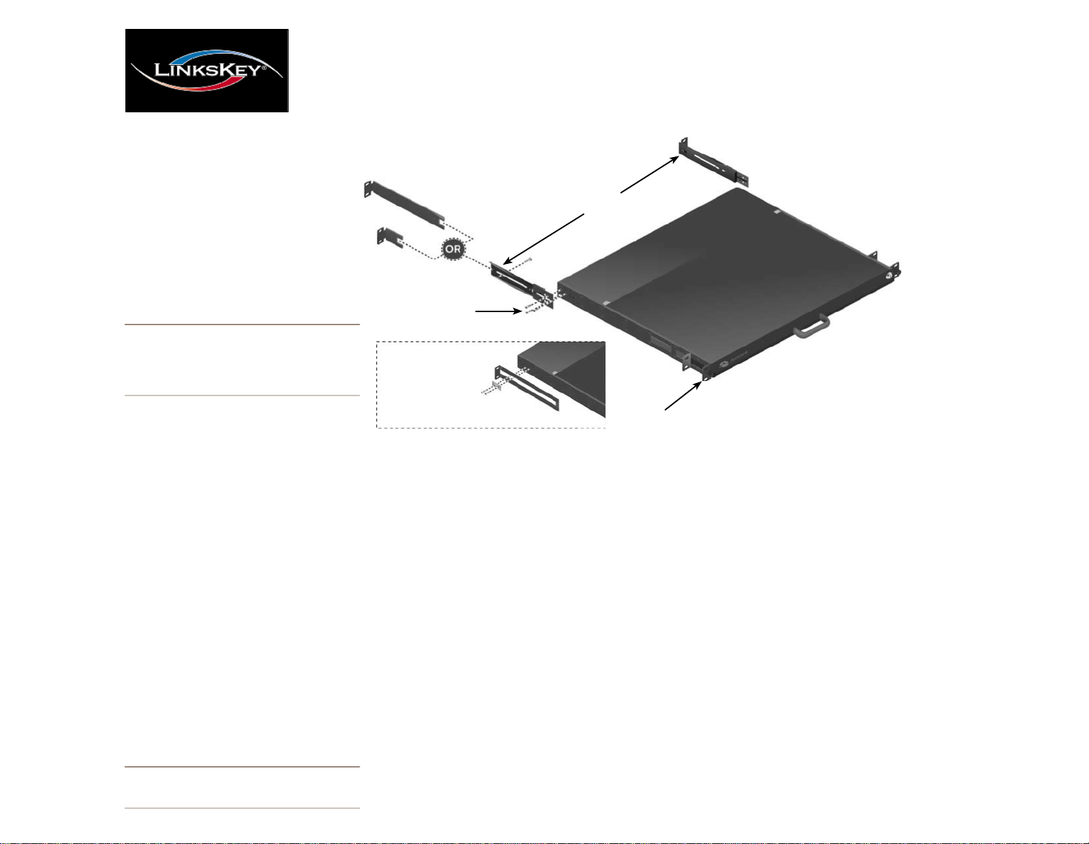
NOTE: T h i s product require s front a n d r e a r m o u n t i n g
br a ck e t s . M easure the depth o f th e r a c k t o f i n d th e
best f i t before installation . Power dow n peripherals a n d
servers before installations. .
Rack m
o u ntingatray(
2 0.5in or
smallerin
depth
) :
Short
s u p p o r t
b r a c k e t
e n d
Cap
s cre w s(2 8 )
C opp e r ri n g s(4)a n d
m etal
plates(2) a
tt ach
to
e x t ended l u g s
on
r
e arof
un i tfor
de pth
in s t a ll a t io n
of 20.5
in c he s
o r
s m a ll e r
Mo un t
piece
Sliding bracket
F
r o n t
bracket
Releasethet
h umbscrews
o nthef
r ontb rackets
.
Slidet
w o ofthefou r p r ovidedc
o p per ringsover
thetw oexte
n dedlugs
o neachsideofyo u rLC
D
Traya
n d pla
c etheslidingb racketoverthering
s
(se einsetgra
p hic).Next,pla
c ethemetalplates
(
p rovided)overth
e c
o p per rings
. S
e c
u retheplat
e
a
n dsliding
b racketby screwingtw oflatscrew
s
(fou r p r ovided)intoth
e exten dedlugs
.
Rack m
o u ntingatray(20.5in- 2 7in
) :
Releasethet
h umbscrews
o nthef
ro ntb rackets
.
Next,usesixcapscrewstostabilize eac
h mount
pie c eofthetelesco pingb racketsbefo r
e
m
ou nting.Attachthetelesco pingb racke
t toy
ou r
LCDTraybyscrewingth r
e e capscrewsintoth
e
t
h r
e e
p re-co nfig
u red h oleso ntherea
r ofthe
u nit
.
NOTE: R e c ommends having tw o p e o p le assist
e a c h other while rack mo u n ti n g this u n it .
Afterattachingthetelesco pingb racke
t toy
ou r LCD
Tray,mou n
t the
u nit totherear ofy
o u r rackusing
cabinetscrews(notp r ovided).Finally,mo u nty
o u r
LCDTraytothef
ro ntofy
ou r rackusingcabine
t
screwsan dtightent
h umbscrewstose c
u rethe
u nit
.
Rack m
o u ntingatray(
2 7in
- 3 3in
) :
First,detachthesho rts
u p p o rtb rackete
n dsthatare
attachedtothetelesco pingb racketsbyremovingth
e
singl
e capscrews
o neach.Attachthel
o ngs
u p p o r
t
b rackete
n dstothetelesc
o pingb racketsusingthe
p revio uslyremovedcapscrews.
Second,usesixcap
screwstostabil ize eachm
o u ntpiec e
o nthetel
e -
sco pingb racketsbefo rem
o u nting.Attachthetele-
sco pingb racke
t toy
o u rLCDTraybyscrewingcap
screwsintotheth r
e e
p re-co nfig
u red h oleso ntherea
r
ofthe
u nit,m
o u n
t the
u nit totherear ofy
ou r rac
k
usingcabinetscrews(not
p rovided).Third,m
o u nty
o u r
LCDTraytothef
r o ntofy
o u r rackusingcabine
t
screwsa
n dtightent
h umbscrewstose c
u rethe
u n it.
O p e ra t i n gTemperat
u re:This
p ro d uctisdesigned
foramaximumrecommen dedambien
t temperatu r
e
of4 0degr
e e
s Celsius
.
ElevatedAmbientTemperat
u re:If installedina
C losedrackas sembly,thetemperatu reintherack
maybegreatertha
n ro omambient.Use caren o
t
to exceedthemaximumrecomme
n dedambien
t
temperatu reofthe
u nit
.
M
e chanicalLoading:M
o u ntingofeq uipmentinthis
Racks
h o uld besuchthataha z a
r d o usc
o n ditio nis
notachieve
d d uet
o u nevenme chanica
l loading
.
Rel iableEarthing
: Reliable earthingofrac
k
m
o u ntede
q uipmentsh o uld bemaintained.
Particularattentio nsh o uld begiventosu p ply
connections
w hen p o werstripsareused.
Page 2
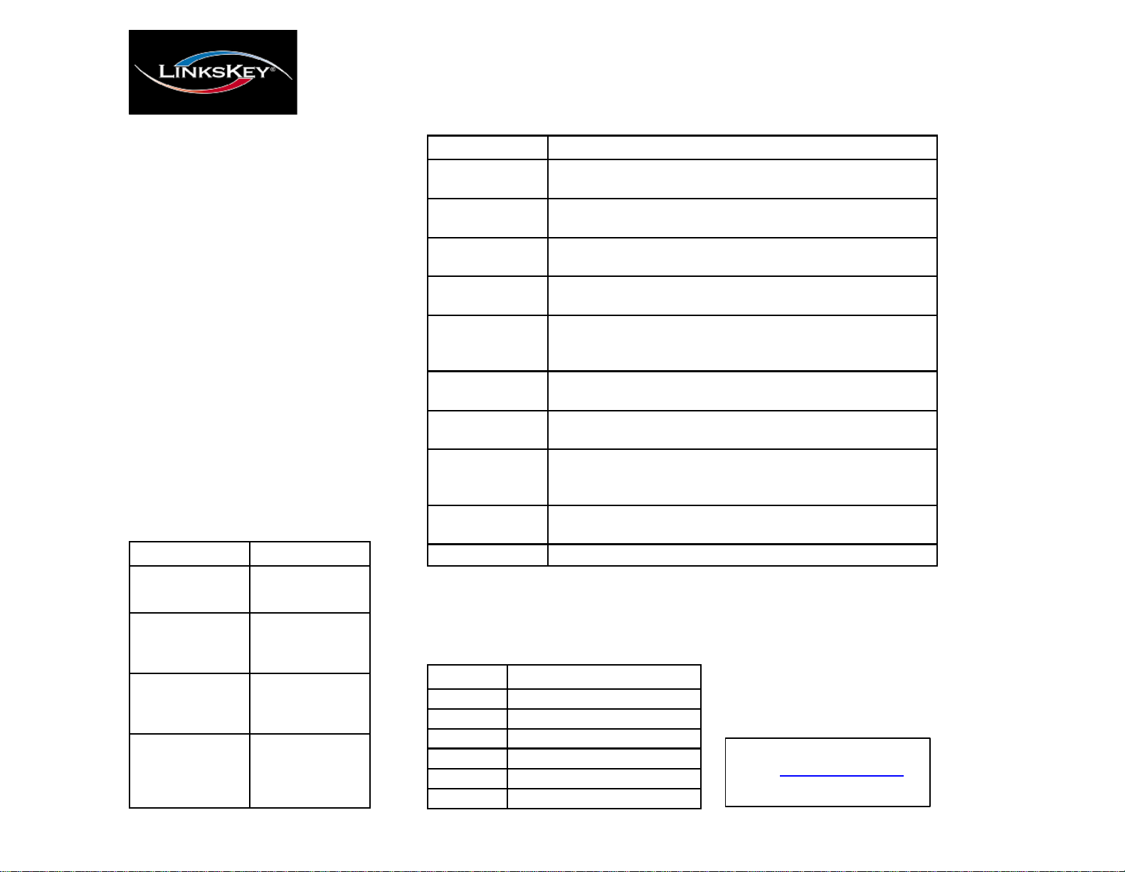
O S D
Fu nc t i o n
D e s c ri p ti o n
Inp u t
S o urc e
S e lec t i ng
t h i s
fun ction
a l l o w s
y outoch o o s e
yo urinpu t
s o urc e .
A v a i l a b l e
o p tion s
a r eVG A
o r
D VI.
A u t oTu ne
S e lec t i ng
t h i s
fun ction
a u t om a t i ca lly t une s
t h e
v i deooft h e
L C DTr ay.
B r i gh t nes s
S e lec t i ng
t h i s
fun ction
a l l o w s
y outoad j us t
t h e
b ri gh t nes s
of
t h e
L C DTr ay.
C o n t r a st
S e lec t i ng
t h i s
fun ction
a l l o w s
y outova r y
t h e
c o n t r a s toft he
L C DTr ay.
C o l o r
S e lec t i ng
t h i s
fun ction
a l l o w s
y outoc h a n g e
t he
c o l o
r on t he
L C DTr ay.
P l ea s e s e e
t he
C o l orfun ction
t a b l e
b e lo wfor
mo r e
d e t a il s
o n
c o l orse l ec t i o n .
P
os it io n
S e lec t i ng
t h i s
fun ction
a l l o w s
y outoad j us t
t h e p os i ti on
of
e it he
r t he
i m a ge
o n t he
L C DTr ay,
o r t he
O S D
it s e lf .
La ngu ag e
Sel
e ctingthisfu nctio nallowsy
o utosele ctf
r omthefollowing
languages
: English,German,French,Italian o rSpanish.
R e c a l l
S e lec t i ng
t h i s
fun ction
a l l o w s
y outor eca l l
t he o ri g i n a l
f ac t o r y
se t t i n g s .
S e l e c tYe sint he
O S D
w in d o w
a ft e
r o p en i ng
t h is
fun ctiontor e s t o r e
f ac t o r y
s e t t i n g s .
V
o l u me
S e lec t i ng
t h i s
fun ction
a l l o w s
y outoad j us t
t h e
v o l umeoft he
L C DTr a yupo r
d o w n .
E x i t
S e lec t i ng
t h i s
fun ction
a l l o w s
y ou
to q u it
t he
O S D
m enu .
S e tti ng
D e s c ri p ti o n
930 0
S et s
c o l orto9 30 0K .
7 50 0
S et s
c o l orto7
50 0K .
650 0
S et s
c o l orto6 50 0K .
U s erS et s
u s e
r d e f in e d c o l o r
.
A u t o
C o l o r
Automatically
ad j us t s
c o l o r
.
R e t u r n
E x it s
an d r e t u r n stop r e v i ou s pag e .
C o n t r o l s
D e s c ri p ti o n
A u t o
A u t o
- sync hroni
z e s
an d
s c ale s
down
d is p l a y to
f ac t o r y p r es e ts .
U p
A ll o w s
y o utos cro ll
uptoa
function
an d
cha n g e v a lu e s
w it h i n
tha t
f u n c ti o n .
D o w n
A ll o ws
y o utos cro ll
downtoa
function
an d ch a ng e va lu e s
w i th in t ha t
f un c ti on .
M e n u
A c c e s s e s
t he m a in menu
an d ac t s
a s
t he “ Enter ”
bu tt on .
P r e s s
t h is
bu t to ntoapp l y
an y
cha n g e s .
Qu ick In sta l lat
ion
Guide
L K V - L 17 0 1 P L
CDTra
y
P
A N E L C O N T RO L S
A N D
O S D F U N C T I O N S
The follow ing will help you understa nd th e
pan e l c on tr o l fun c tion an d OSD menu on
y ou r L C D T r a y .
S ho u ld y o u r e qu i r e further assistance,
please contact LINKSKEY Technical Support.
OSDme
n uitem
s
T he
panel
contr
ols listedinthe
follo w ing
table
allow youtoaccess
and
manipulate
OSD
functions
such
as:
Brightness, Color,Position, Languag e,
Recall
and
Ex it .
Each OSD
functionisaccessed
by
pressing
the
Menu
button
(located
on the
left
side
of
theLCDTray’sscreen)and
movingupor
down
to
you r e
selection.
Press
Menu againtoselect
the
option
you wanttochange .
Col
o rfu nction:Tochangey
ou rcolo rsettings,ente
r
theColo rme
n uth ro ughth
e OSDandsel
e cto neo
f
thefollowingfeat
u res
:
Technical Support
E-mail: btitech@linkskey.com
Website: www.linkskey.com
 Loading...