

Page 1
Quick Installation Guide LKV-E412 CAT5555 USB KVM Extender Set
INSTALLATION
Quick Installation Guide
CAT5 USB KVM Extender
LKV-E412
Built-in KVM Switching on the
Remote Console for More Versatility
Thank you for purchasing the LKV-E412 CAT5 USB KVM Extender
Set! The CAT5 USB KVM Extender Set comprises two units – one
Transmitter (Tx) Unit and one Receiver (Rx) Unit. With our highly
reliable and quality product, users can enjoy countless benefits
from using it.
INTRODUCTION
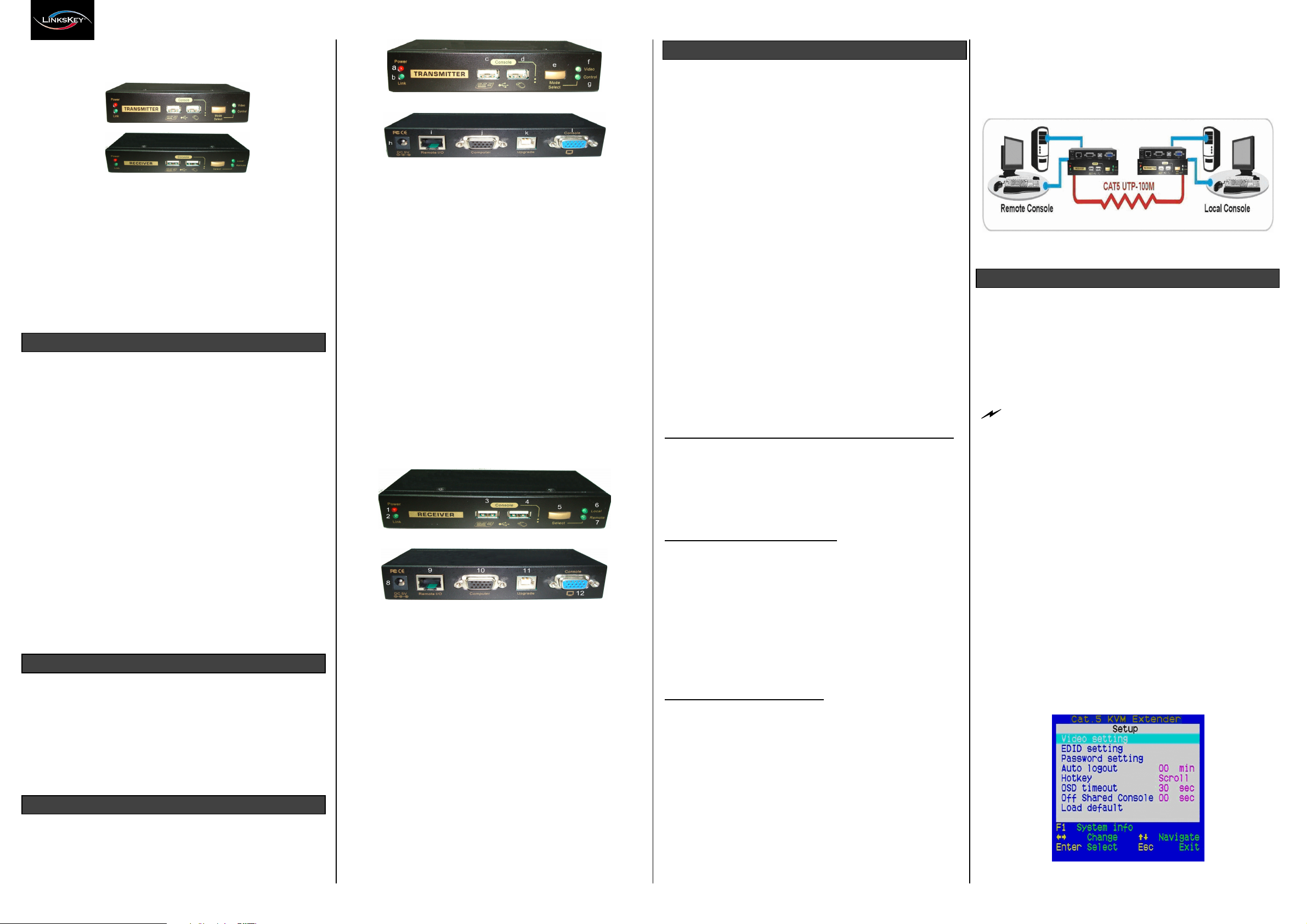
The LKV-E412 CAT5 USB KVM Extender Set – extends your
keyboard, mouse, and monitor from your computer up to 100M
(328ft) away on a single CAT5 UTP cable, with satisfying video
quality.
The CAT5 USB KVM Extender Set comprises two distinct units The Receiver (Rx) Unit and the Transmitter (Tx) Unit. The Tx Unit
and the Rx Unit will be located each on one end of the CAT5 UTP
cable. The Transmitter allows user to access the computer at the
local end, while extending it across 100M(328ft) to the Remote
console on the Receiver, which can therefore access and control
the extended computer as well as another computer in proximity of
the Receiver, due to a built-in KVM Switching feature into the
Receiver.
It is especially useful for setting up a highly flexible computer/user
topology over a sizable distance up to 100M(328ft) away.
Applicable either over an exhibition room, work floor, security room,
locked server room, or other mission-critical scenarios, the CAT5
USB KVM Extender Set allows you to locate your server physically
far back from the user due to security or spatial concerns. And it
allows the user to manage and control the computer at both
locations, and with the capability of switching between the original
computer and a second computer on the Receiver end.
PACKAGE CONTENTS
Please check whether you have all the following items within the
packaging box:
Transmitter (Tx) Unit x 1
Receiver (Rx) Unit x 1
Slim 3-in-1 PS/2 & USB KVM Combo-free Cable x 2
Power Adapters (DC5V / 2.0A) x 2
This Quick Installation Guide x 1
FRONT - PANEL & BACK - PANEL VIEW
The front and back panels are where the various connectors are
located on the two pieces of the CAT5 USB KVM Extender Set.
Before you connect these two units to any computer, cabling
accessories or peripherals, you should get a glimpse of the main
connectors you are going to encounter when setting up the system.
Transmitter (Tx) Unit – Front Panel
Transmitter (Tx) Unit – Back Panel
Transmitter Unit (Local End Connection)
[Tx – Front Panel]
a. Power LED (ON: Power on / OFF: Power off)
b. Link LED (ON: Link OK / OFF: No Link)
c. Console USB keyboard connector (USB Type A)
d. Console USB mouse connector (USB Type A)
e. Mode Select button for selecting Receiver Unit access mode
(Full Access / View Only / Access Deny)
f. Video LED (ON: Remote video on / OFF: Remote video off)
g. Control LED (ON: Remote K/B & Mouse control enable / OFF:
Remote K/B & Mouse control disable)
[Tx – Back Panel]
h. Power jack (DC 5V, center-positive)
i. Remote I/O port (RJ-45, connect to the Receiver Unit via a
CAT5 UTP cable, 100M/328ft max.)
j. Computer port (HDB-15, connect to the local computer using a
special 3-in-1 KVM Combo-free cable)
k. Upgrade port (USB Type B, dedicated for firmware upgrade
use)
l. Console video port (HDB-15, connect to monitor)
Receiver (Rx) Unit – Front Panel
Receiver (Rx) Unit – Back Panel
Receiver Unit (Remote End Connection)
[Rx – Front Panel]
1. Power LED (ON: Power on / OFF: Power off)
2. Link LED (ON: Link OK / OFF: No Link)
3. Console USB keyboard connector
4. Console USB mouse connector
5. Select toggle button for switching Local / Remote computer
6. Local LED (ON: Local computer active / OFF: Local computer
inactive)
7. Remote LED (ON: Remote computer active / OFF: Remote
computer inactive)
[Rx – Back Panel]
8. Power jack (DC 5V, center-positive)
9. Remote I/O port (RJ-45, connect to the Transmitter Unit via a
CAT5 UTP cable, 100M/328ft max.)
10. Computer port (HDB-15, connect to the local computer using a
special 3-in-1 KVM Combo-free cable)
11. Upgrade port (USB Type B, dedicated for firmware upgrade
use)
12. Console video port (HDB-15, connect to monitor)
Before you install the two pieces of the CAT5 USB KVM Extender
Set, you should have these items on the checklist ready:
1. The computer for extension should be one with USB
interfaces.
2. You should check the display mode of the computer to be
within 1600 x 1200 pixel dimension. And refresh rate to be one
that is more commonly used such as 60Hz, etc.
3. Prepare two sets of keyboard, mouse, monitor - one set for TX
Local console and the other set for RX Remote console.
4. The two monitors (one on the Tx side and the other on the Rx
side) used for display should be of the same resolution, and
better of the same type, same made and model.
5. Since the CAT5 USB KVM Extender Set supports only
standard 5-button mouse and keyboard, any more advanced
mouse / keyboard function will not be supported.
6. Use good quality CAT5 UTP cable, 100M(328ft) max.. Note
that better quality cable will give better video outcome with
longer distance span.
7. Any cabling distance longer than 100M(328ft) will experience
more signal degradation with longer span. However, better
quality cable can reach out farther away.
8. The choice of path of the CAT5 UTP cable should not only
take into account the shortest possible path, but also consider
any significant electromagnetic may interference source
factors too.
9. There should be power outlets near where you locate the
CAT5 USB KVM Extender Set.
Take the package items out of the box and begin installation
Plan the Layout Path and Deploy the UTP Cable for Extension
1. Plan the path through which the CAT5 UTP cable will be
deployed across the distance between the Transmitter and the
Receiver. You should choose the layout path not only base on
shortest be deployed across the possible length consideration,
but also on least electromagnetic interference.
2. Lay out the CAT5 UTP cable according to your planned path.
Configuring the Transmitter Console
3. Connect one end of the CAT5 UTP cable to the Remote I/O
port (connector i) of the Transmitter.
4. Connect the AC power adapter to the power jack (connector h)
of the Transmitter to power it up before connecting any
devices to it.
5. Connect the computer to the Computer port (connector j) of
the Transmitter, using the 3-in-1 KVM Combo-free cable.
6. Connect a keyboard, mouse, and monitor to the Transmitter’s
Console ports (connector c, d, and l).
7. Power on the computer and check the keyboard, mouse, and
video are working fine, and then go to the next step.
Configuring the Receiver Console
8. Connect the other end of the CAT5 UTP cable from the
Transmitter to the Receiver’s Remote I/O port (connector 9).
9. Connect the AC power adapter to the power jack (connector 8)
of the Receiver to power it up before connecting any devices
to it.
10. Connect a keyboard, mouse, and monitor to the Receiver’s
Console ports (connector 3, 4, and 12).
11. Switch to Remote by using Select button then check the
keyboard, mouse, and monitor are working fine. At this time,
the video might be blurred since it is not yet adjusted and
optimized.
12. Adjust the video parameters to optimize the display output
(Refer to OSD Menu / Video Setting section for details).
13. Connect the computer to the Computer port (connector 10) of
the Receiver, using the 3-in-1 KVM Combo-free cable.
.
14. Switch to Local by using Select button then power on the
computer and check the keyboard, mouse, and video are
working fine.
Now, you have set up the whole system and can operate
immediately ….
LKV-E412 CAT5 USB KVM Extender Configuration Diagram
OPERATION
On the Receiver Unit, the OSD (On-Screen Display) Menu control
is available to facilitate more intuitive operations. Users can
configure various settings by the OSD Menu.
OSD Menu (Only Available on Receiver Unit)
To evoke the OSD Menu, you should hit the following keyboard
hotkeys:
Hotkey sequence = [Scroll Lock] + [Scroll Lock] + [Space Bar]
within 2 seconds. Otherwise, the hotkey sequence will not be
validated.
To navigate the OSD Menu, just use the following keys:
These keys are listed explicitly on the OSD setting page for your
ready reference.
OSD Main Page
This is the OSD main menu and it is the first page you will see
when you hit the keyboard hotkeys - [Scroll Lock] + [Scroll Lock]
+ [Space Bar] - to evoke the OSD Menu. (The default keyboard
hotkey is [Scroll Lock])
Note: There are two methods to setup the keyboard hotkeys
1. OSD Menu (Only available on Receiver Unit)
2. Keyboard (Only available on Receiver Unit)
Each keystroke within a hotkey sequence should be pressed
Esc: Exit
Left/Right cursor: Change value in the menu option
Up/Down Cursor: Navigate
F10: Log out the OSD Menu (However, if the password
protection is not enabled, the Logout feature will not be
available.)
Main Menu
1
Rev. 1.1 Copyright© All rights reserved.
Page 2
Quick Installation Guide LKV-E412 CAT5555 USB KVM Extender Set
Press keyboard function key F1 for System Information Menu.
System Information Menu
Video Setting:
Here you can enter a submenu to configure the video settings such
as Brightness, Sharpness and skew compensation for Phase Red
and Phase Green.
Video Setting Menu
Brightness: [0 ~ 63]
Adjust the Brightness of the Display on Receiver Console.
Sharpness: [0 ~ 63]
Adjust the Sharpness of the Display on Receiver Console.
Phase Red: [-31~+31]
Specify the time delay for red color.
Phase Green: [-31~+31]
Specify the time delay for green color.
The blue component color is adjusted automatically in proportion to
the red and green.
To achieve optimized video output on the Receiver unit that may
be 100 meters away from the local computer on the Transmitter
unit, users might adjust these various parameters conscientiously.
For a more detailed guideline of how to adjust your video display
parameters on the Receiver console, please refer to next section,
Optimize the Video Display on the Remote Console.
EDID Setting:
EDID Setting Menu
TX EDID:
Select and set the TX monitor EDID emulation data either of the
monitor EDID information on the RX or TX unit.
Read Monitor:
Read and store the RX and TX monitor EDID information data for
use for TX unit.
RX Monitor:
Show the RX monitor EDID information data.
TX Monitor:
Show the TX monitor EDID information data.
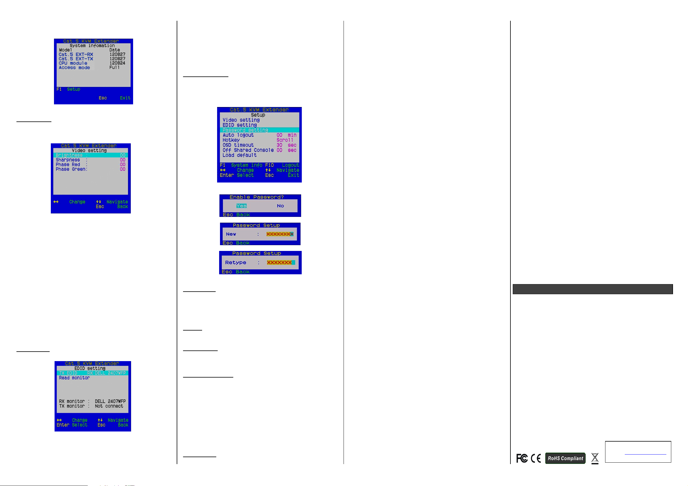
Password Setting:
Disable / Enable the password protection feature. If the password
is enable, after you log out or the Auto logout has timed out, you
will be prompted for the correct password before you can access
the console again.
Password Setting Menu
Auto Logout:
Disable / Enable the logout timeout (0~10min, 0 = Disable).
The Auto logout time can be configured from 0 (Disable), with an
increment of 1 minute and right up to 10 minutes. If the password
protection is not enabled, the Auto logout feature will not be
available.
Hotkey:
Change the keyboard hotkey preceding sequence from [Scroll
Lock] default to [Caps Lock], [Num Lock] or F12.
OSD Timeout:
Configure the OSD timeout value starting from 20 seconds, with an
increment of 5 seconds and up to 60 seconds (0~60 seconds, 0 =
Disable).
Off Shared Console:
Configure the Off Shared Console control timeout value (3, 5, 10,
20, 30 seconds, 0 = Disable).
Local and Remote switching engaged priority offers “Deadlock”
function, the “Deadlock” function locks the Console control while
current user (either one on the RX or TX) was using, the other user
have to wait until the current user released the process control, or
there is no activity for the timeout period then the other user can
access the Console control.
When the “Deadlock” function is active, both “Video” and “Control”
LEDs on Transmitter unit will flash, until either the current user
released the process control or the timeout period has expired.
Load Default:
Load the factory default settings.
Change the Hotkey Preceding Sequence from
Keyboard (Only Available on Receiver Unit)
To change the keyboard hotkey preceding sequence (or trigger
sequence) of your hotkeys, please hit the following key commands:
Hotkey sequence = [Scroll Lock] + [Scroll Lock] + H +(y)
(y) = Caps Lock, F12 or Num Lock
Note that the hotkey preceding sequence setting on the Receiver
Console will also affect the hotkey preceding sequence on the
Transmitter Console, which the Transmitter Console will use the
same keyboard hotkey as the Receiver Console. In addition to
using the keyboard hotkey command, also can use the OSD menu
to change the hotkey preceding sequence. Please refer to the
previous section.
Change Remote Console ON / OFF and View Only
from keyboard (Only Available on Transmitter Unit)
While you are at the Transmitter Console, you can turn Remote
Console on and off or make it View Only by the following hotkey
commands:
Hotkey sequence = [Scroll Lock] + [Scroll Lock] + M + (y)
(y) = 1, 2, 3
(y) = 1, On (Full access control of keyboard, mouse and video)
(y) = 2, Off (No access control of keyboard, mouse and video,
video off)
(y) = 3, View Only (No access control of keyboard, mouse and
video, video on)
When the Remote Console is turned off, the monitor display will
become blank and the keyboard and mouse will be disabled. Thus,
the hotkey provides a security measure for refuse and grant
access on Remote Console. When Remote Console is View Only,
user may see the screen video but not access to the keyboard,
mouse and video control.
Switch between the Local and Remote Computer
from keyboard (Only Available on Receiver Unit)
In addition to using the switching button on the front panel of the
Receiver unit to switch between the Local and Remote computer,
you can also use the keyboard hotkey commands:
Hotkey sequence = [Scroll Lock] + [Scroll Lock] + (y)
(y) = ,
(y) = , Local (Computer)
(y) = , Remote (Computer)
Optimize the Video Display on the Remote Console
To achieve an optimized display output on the Receiver unit
(Remote Console) that it requires you to conscientiously adjust the
various video parameters such as Brightness and Sharpness in an
optimized combination.
Please follow the procedure below to achieve an optimized video
display output on your Receiver unit Console display:
1. Choose a video display content that you think will be suitable
2. Adjust the Brightness and Sharpness:
to serve as a reference for the visual adjustment. You can
choose a document that integrates texts and graphics so that
you can use it as a reference to achieve an optimized video
display for either textual or graphic content on the Receiver
unit Console display output. One alternative can be the visual
testing program which provided by the display card vendor.
First, invoke the OSD Menu by hitting the keyboard hotkey,
[Scroll Lock] + [Scroll Lock] + [Space Bar], then go to the
Video setting submenu.
Next, adjust your screen display for an optimized output. The
Brightness adjustment can help you tuning the video display
luminance as a whole to lighter or darker output that best suits
your visual perception.
The Sharpness is the edge contrast that you will perceive.
Adjust the Brightness:
The brighter the video display, the more luminance will be
added to the video output.
Adjust the Sharpness:
Adding more sharpness to the video display will help you
distinguish more details out of the edges of a line or shape.
When you have adjusted to the desired level of the Brightness and
Sharpness, you can then keep going on the next step the Red
Delay and Green Delay adjustment to achieve an optimized video
display output.
3. Adjust the Red Delay and Green Delay:
The Red, Green and Blue are the primary colors that
constitute our color perception scheme on the monitor.
The LKV-E412 CAT5 USB KVM Extender Set uses different
wires in a CAT5 UTP cable to carry the different primary
colors. The wire lengths of different wires in a CAT5 UTP
cable are slightly different, the longer the CAT5 UTP cable the
greater the difference in length between wires.
The different travel times cause the primary colors out of sync
on the screen, you will need to adjust the delay time for certain
color signals on certain wires to make the three colors come
into the display screen in good sync.
The LKV-E412 CAT5 USB KVM Extender Set may need to
manually adjust only the Red delay and the Green delay. As
regards the Blue delay, is automatically tuned and optimized
by the system according to other concurrent video parameters.
The values of the Red delay and the Green delay will be
limited within a preset difference range. This means,
whenever you try to adjust either the value of the Red delay or
the Green delay to be beyond the allowable preset difference
range as compared to the value of the other color delay, the
other color delay will be automatically adjusted and come
closer to be within the difference range to prevent the video
from being perceptibly disoriented.
With the Blue delay automatically tuned in to the other colors
and the Red and the Green delays limited within a comfortable
difference range the LKV-E412 CAT5 USB KVM Extender Set
facilitates an easier and more perceptive way for video
optimization.
No Video Troubleshooting
Q. When I connect a monitor to LKV-E412 CAT5 USB KVM
Extender, the video doesn’t show up on the screen. What can
I do?
A. If you encounter no video or aberrant display problem with a
specific monitor, please refer to the EDID Setting section, if the
problem persists please contact Linkskey for technical support.
FCC / CE Statements
FCC Statement: This equipment has been tested and found to
comply with the regulations for a Class B digital device, pursuant to
Part 15 of the FCC Rules. These limits are designed to provide
reasonable protection against harmful interference when the
equipment is operated in a commercial environment. This
equipment generates, uses, and can radiate radio frequency
energy and, if not installed and used in accordance with this Quick
Installation Guide, may cause harmful interference to radio
communications. Operation of this equipment in a residential area
is likely to cause harmful interference in which case, the user will
be required to correct the interference at his/her own expense.
CE Statement: This is a Class B product in a domestic
environment, this product may cause radio interference, in which
case the user may be required to take adequate measures.
Technical Support
E-mail: btitech@linkskey.com
Website: www.linkskey.com
2
Rev. 1.1 Copyright© All rights reserved.
 Loading...