

Linkskey LKS-FCM22C/T-2, LKS-FCS22C-20, LKS-FCS22C-40, LKS-FCS22C-60, LKS-FCS21C-T/R40 User Manual
...Page 1
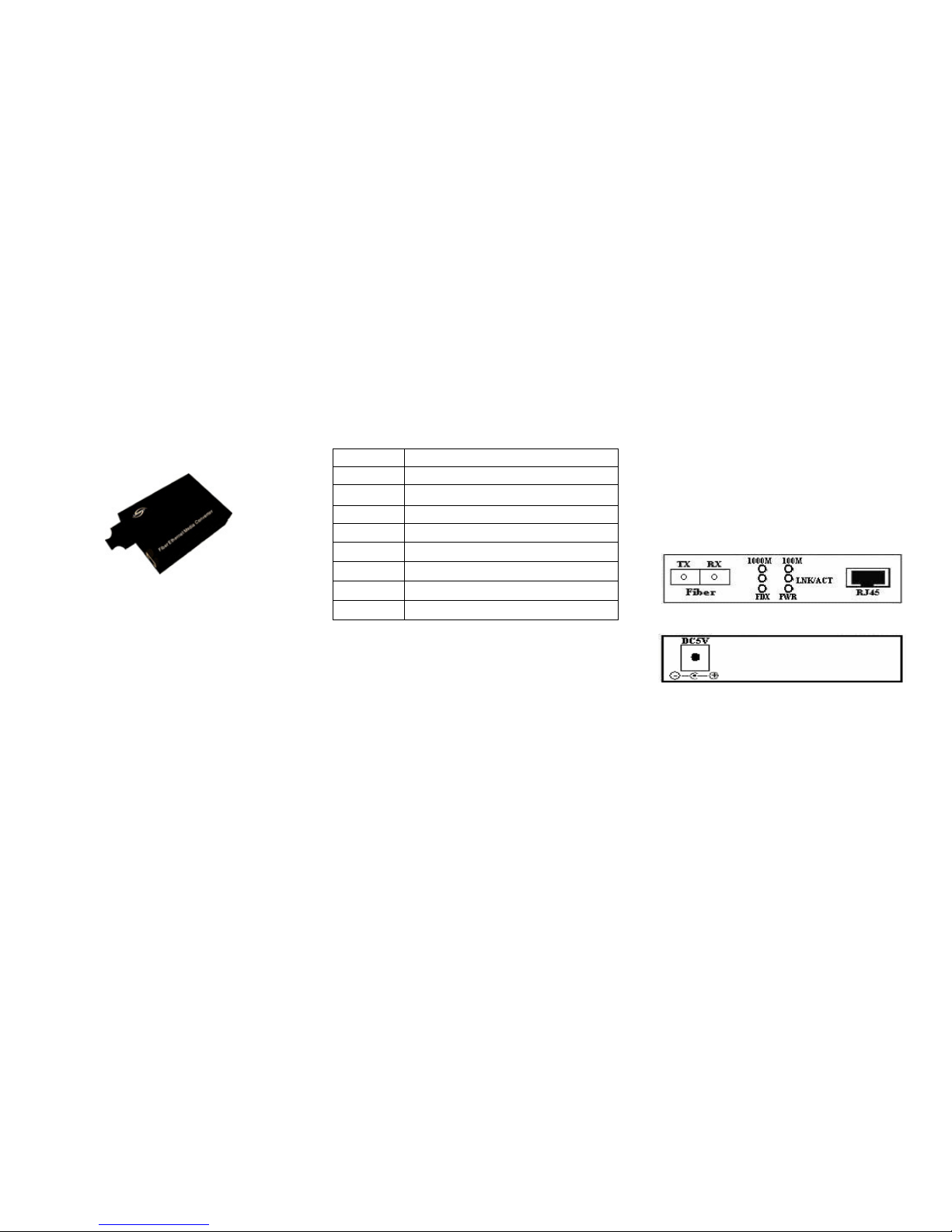
LinksKey
Gigabit Ethernet
Fiber
Media Converter
User Manual
V 3.1
Brief introduction
Thank you for purchasing Linkskey Gigabit Ethernet
Fiber Media Converter! It provides a media conversion
allowing high-speed integration of fiber optic and twistedpair segments. The fiber media converter provides seamless
translation between fiber optic and Gigabit Ethernet
networks.
The table below is for purchasing information:
Model Specifications
LKS-FCM22C/T-2
100TX to 100FX Multi-Mode SC/ST Fiber Converter (2km, 1.2mi)
LKS-FCS22C-20
100TX to 100FX Single-Mode SC Fiber Converter (20km, 12.4mi)
LKS-FCS22C-40
100TX to 100FX Single-Mode SC Fiber Converter (40km, 24.9mi)
LKS-FCS22C-60
100TX to 100FX Single-Mode SC Fiber Converter (60km, 37.3mi)
LKS-FCS21C-T/R40
100TX to 100FX Single Fiber WDM Tr
ansmitter/Receiver
Single-Mode SC/ST Fiber Converter (40km, 24.9mi)
LKS-FCM32C/T-05
1000TX to 1000FX Multi-Mode SC/ST Fiber Converter (550m,1
804ft)
LKS-FCS32C-20
1000TX to 1000FX Single-Mode SC Fiber Converter (20km, 12.4mi)
LKS-FCS31C-T/R20
1000TX to
1000FX Single Fiber WDM Transmitter/Receiver
Single-Mode SC Fiber Converter (20km, 12.4mi)
Package content
Please check the following items have been included in the
package:
• Gigabit Ethernet Fiber Media Converter x 1
• AC switching power adapter x 1
• User manual x 1
• Product warranty card x 1
Please contact the local reseller immediately for any loss or
damage to the above items.
Installation
Before you begin the installation, check the AC voltage of your
area. The AC power adapter which is used to provide the DC
power for the unit, and should have the AC voltage matching
the commercial power voltage in your area.
Applying Power
1. Connect the DC plug to the DC input jack located on the back
of the media converter before connecting to the AC power outlet.
2. To ensure against accidental disconnection, tie the DC power
cable with the cable tie located the back of the media converter.
3. Connect the AC power adapter to the AC power outlet.
4. Check the Power LED indication on the media converter.
Making TP Port Connection
TP port is featured to support connection to:
• Auto-negotiation devices
• Auto-negotiation incapable 10Base-T devices
• Auto-negotiation incapable 100Base-TX devices
• Auto-negotiation incapable 1000Base-T devices
Network Cables
• 10Base-T:2-pair UTP CAT 3,4,5, EIA/TIA-568 100-ohm STP
• 100Base-TX:2-pair UTP CAT 5, EIA/TIA-568 100-ohm STP
• 1000Base-T:4-pair UTP CAT 5e,6 EIA/TIA-568 100-ohm STP
• Link distance: Up to 100 meters
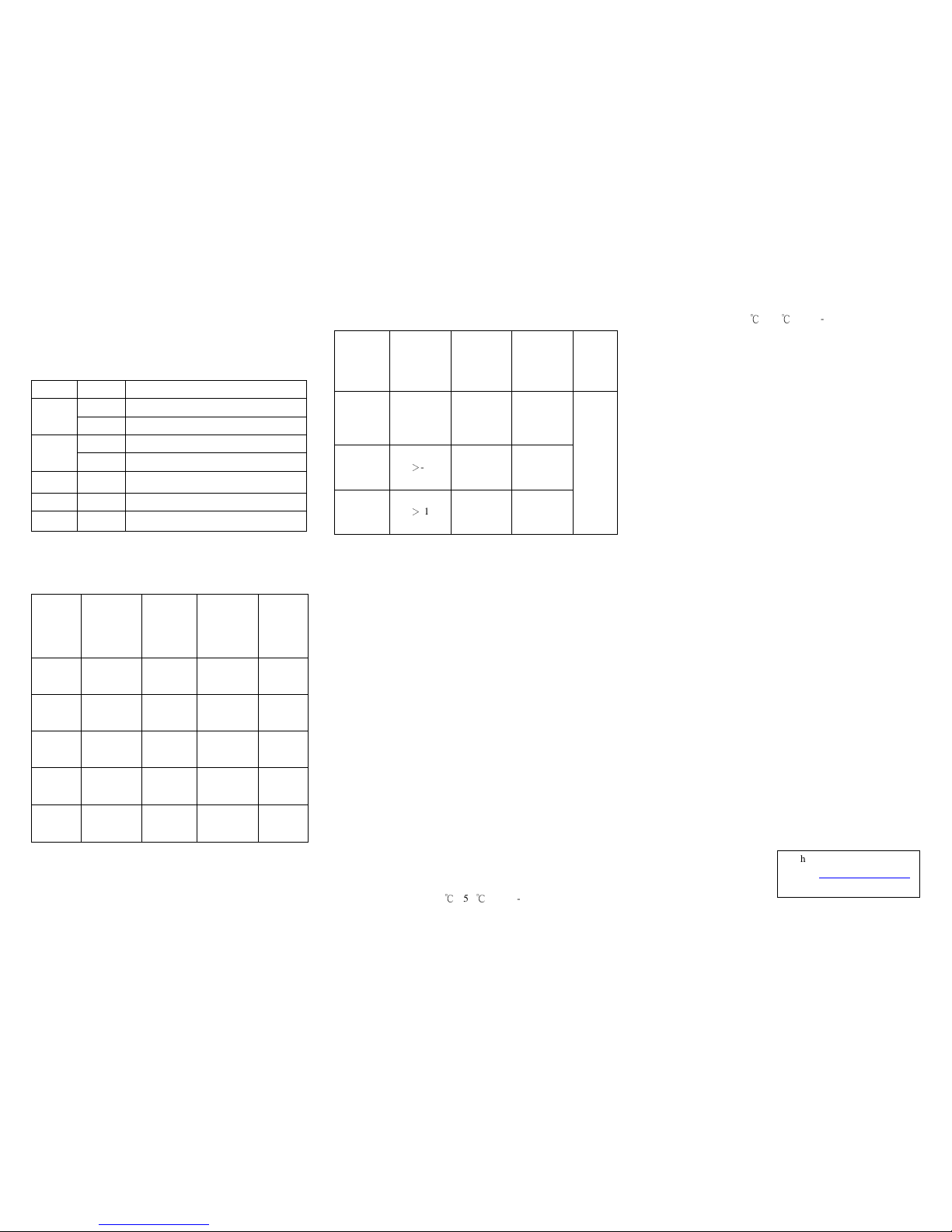
Figure 1. Front Panel
Figure 2. Back Panel
Making FX Port Connection
FX port operates at 1000Mbps and full duplex (factory default).
A variety of fiber options is listed in next section. Since the
WDM (Wavelength Division Multiplexing) single fiber media
converters use different wavelengths for transmission and
receiving respectively, the link partner device located on the
remote end of the single fiber should match the wavelength
used on the single fiber converter. Using 50/125 or 62.5/125
micron multi-mode fiber cable to connect to the fiber port of
multi-mode media converter. Using 9/125 micron single-mode
fiber cable to connect to the single-mode media converter.
Note: All optical fiber media converters must be used in pair.
Single fiber optic media converter, the TX model must be
paired with the RX model and vice versa.
Page 2
LED indicators
LED indicators serve as device monitoring and error display.
The following is the explanation for each LED indicator.
LEDs State
Indication
On
TP/Fiber link connection established
Link/Act
Blinking
TP/Fiber transmitting or receiving data
On
Connection in full duplex mode
FDX
Off
Connection in half-duplex mode
PWR On
Power on
1000 On
TP connection speed is 1000Mbps
100 On
TP connection speed is 100Mbps
Transmission characteristics of dual fiber converter
Dual
Fiber
Transmitting
optical
power
(dBm)
Receving
sensitivity
(dBm)
Transmission
distance
(km)
Loss
allowed
(dBm)
MM/SC/
1310nm
-10 ~ -5
-23
0.55
7
SM/SC/
1310nm
-9 ~ -3
-24
20
11
SM/SC/
1310nm
-2 ~ 3
-24
40
20
SM/SC/
1550nm
-3 ~ 2
-24
60
19
SM/SC/
1550nm
-3 ~ 2
-24
80
24
Transmission characteristics of single fiber converter
Single
Fiber
Transmitting
optical power
(dBm)
Receving
sensitivity
(dBm)
Transmission
distance
(km)
Loss
allowed
(dBm)
SM/SC/
1310/1550
-3 ~ -9 -24 20
SM/SC/
1310/1550
>
-4
-24 40
SM/SC/
1490/1550
>
-1
-24 60
Standard
loss:
1310nm-
0.4/km;
1550nm-
0.25/km;
1490nm-
0.25/km
Main feature
1. Built in high efficiency SRAM for packet buffer, with 1K
entry lookup table and 4-way associative hash algorithm
2. Half-duplex back-pressure and IEEE802.3x full duplex flow
control
3. Auto MDI/MDI-X detection function on the TP port
4. Support link fault pass through function
5. Support far end fault function on the FX port
6. LED display for easy monitoring of device status
7. Transmission distance 550m multi-mode, 120km
single-mode
8. Low power consumption
Technical parameters
1. Standard: IEEE 802.3 10Base-T standard,
IEEE 802.3u 100Base-TX/FX standard,
IEEE 802.3ab 1000Base-T standard and
IEEE 802.3z 1000Base-FX
2. Protocol: CSMA/CD
3. Connector: one UTP RJ-45 connector, one SC/ST connector
4. Operation mode: full duplex mode or half-duplex mode
5.
Power consumption: 5V DC 1A (4.5W max.)
6. Operation temperature: 0 ℃- 55 (32℃˚F - 131˚F)
7. Storage temperature: -20
℃
- 70 (℃-4˚F - 158˚F)
8.Relative humidity: 5%-90%
9. TP cable:
10Mbps - Category 3, 4, or 5 UTP
100Mbps - Category 5 UTP
1000Mbps - Category 5e or 6 UTP
10. FX cable: Multi-mode - 50/125, 62.5/125 or 100/140µm
Single-mode - 8.3/125, 8.7/125, 9/125 or 10/125µm
11. Dimensions: 94mm x 70mm x 26mm (3.7in x 2.8in x 1.0in)
Cautions:
1. This product is suitable for indoor application.
2. Put on the dust cover of fiber interface when not used.
3. It is forbidden to stare at the TX fiber-transfer end with naked eyes.
Troubleshooting:
1. Fail to transmit data: Make sure the UTP distance does not exceed
100m, and the fiber distance does not exceed the maximum
distance. Verify that both nodes are running at the same speed.
2.
UTP or Fiber Link LED is not lit: Check the power on the
network device connected to the converter, make sure it is
turned ON. Check the cables, make sure the UTP cable
complies with EIA/TIA 568 specification and fiber optic
cables comply with industry standards.
Technical Support
E-mail: [email protected]
Website: www.linkskey.com
 Loading...