

Linkskey LDV-DM202AUSK User Manual
Quick Installation Guide Applicable models: LDV-DM202AUSK/LDV-DM204AUSK 2/4-port Dual Monitor DVI KVM Switch w/ Audio&Mic
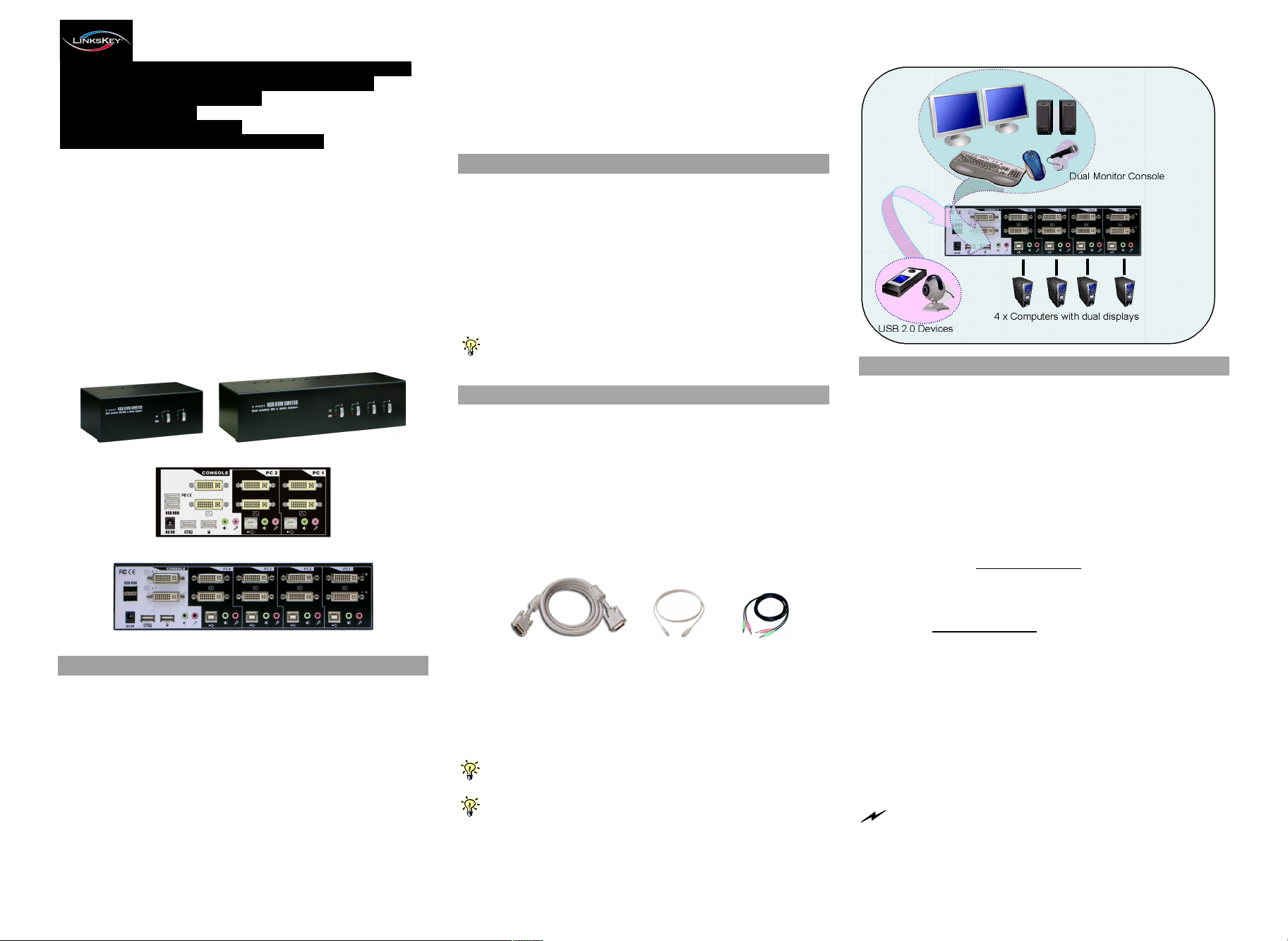
4 x Computers with dual displays
True Transparent USB Emulation for Keyboard and Mouse
All-Time Full DDC Emulation for Video Compatibility
Digital and Analog Video Support
2 x USB 2.0 Hub Ports
Audio&Mic Switching Support
User-Definable Hotkey Preceding Sequence
LDV-DM202AUSK/LDV-DM204AUSK
2/4-port Dual Monitor DVI KVM Switch
w/ Audio&Mic
True Transparent USB Emulation
Quick Installation Guide
Thank you for purchasing the LDV-DM202AUSK/LDVDM204AUSK Dual Monitor DVI KVM Switch w/ Audio&Mic!
With our highly reliable and quality product, user can enjoy
countless benefits from using this KVM Switch.
LDV-DM202AUSK LDV-DM204AUSK
LDV-DM202AUSK - Back Panel
The LDV-DM202AUSK/LDV-DM204AUSK supports All-Time
Full DDC Emulation so that it can guarantee a maximum
compatibility with video requirements. It supports digital
resolution up to 1920 x 1200, analog resolution up to 2048 x
1536.
Before you install
The default setting of the LDV-DM202AUSK/LDV-DM204AUSK
is appropriate for most systems. You do not need to configure
the KVM Switch before installation. Please follow the
instructions below for the setup sequence:
T h e
correct s e t up sequ e n ce
(1) P o w e r up y o u r K V M Sw i t ch by co n n ec ting th e ext e rn a l
p o w er a d a p t e r to i t … .
( 2 ) T h e n con n e c t th e s ha r e d k e yb o a r d , m o nit o r and m o u s e
(al s o s p e ake r s e t a n d m i c r o p ho n e ) to the K V M S w itc h , a n d t h e n
con n e c t you r co m p u ters.
Si n c e U SB i n t e r f a c e i s h ot - pl u g g a b le, y o u d on ’t h a v e to tu r n o ff t he
com p uter b e f o r e m ak ing con n e c tio ns to th e US B K VM .
is … …
Out-of-the-box Installation
Take the KVM Switch out of the box and begin installation….
Step 1. Power up your KVM Switch by connecting the external
power adapter to it.
Step 2. Connect the shared USB keyboard, mouse, two
monitors and the speaker system and microphone as
well as other shared USB devices to the KVM switch.
Step 3. Connect each of your computers to the KVM switch
using the DVI-I video cable, USB (Type A-to-Type B)
cable and audio & Mic cables (see the pictures below).
Easy Operation
There are two methods to control your KVM Switch for PC, USB
hub port as well as audio/mic channel selection: using the front-
panel push buttons or a hotkey sequence.
Front-panel buttons
The front-panel buttons let you have direct control over KVM
switch operation and channel switching. Simply press the PC
button for PC port switching (and if binding is enabled between
PC / USB hub port control / audio&mic switching, they will be
jointly selected at the same time). If you want to enable the
binding of PC / Hub port control / Audio&Mic switching, use the
hotkey sequences. See Quick Reference Sheet
Keyboard hotkey
Introduction
The LDV-DM202AUSK/LDV-DM204AUSK Dual Monitor DVI
KVM Switch utilizes the latest True Transparent USB (TTU)
Emulation Technology to ensure full compatibility to all USB
keyboards and mice and also guarantee fastest switching speed.
By using the TTU Technology, KVM users will no longer suffer
any comprise to keyboard and mouse functionalities and can
enjoy their full capability. Hence this KVM Switch is especially
designed for use with gaming keyboard and gaming mouse. Its
two extra USB 2.0 hub ports are for sharing high-speed USB 2.0
devices. Thus, your investment on this KVM Switch is further
ensured and its life-time value just maximized!
LDV-DM204AUSK – Back Panel
DVI – I USB cable Audio&Mic
Video Cable (Type A-to-Type B)
Step 4. (Now your KVM Switch should have been powered-up….)
Power up the connected computers one by one. After
your computers are powered up, the keyboard and
mouse will be recognized and now you can begin
operating the KVM switch.
And also you should verify the USB device on your USB Hub Ports
are fully functioning after installation of its driver on both connected PCs.
If you need to connect to the analog video source (HDB15), you
might need to use a HDB-DVI adapter to facilitate connection with the
KVM switch.
Rev. 1.8 Copyright© All rights reserved
A keyboard hotkey sequence consists of at least three specific
keystrokes: See Quick Reference Sheet
Hotkey sequence = [ScrLk]* + [ScrLk] * + Command key(s)
* User-definable = SCROLL LOCK, CAPS, ESC, F12 or NUM LOCK
Hotkey preceding sequence configuration: For users who want to use
a preceding sequence other than two consecutive Scroll Locks, there is
also one convenient way to configure it. (1)Hit ScrollLock + ScrollLock +
H, then two beeps will signal readiness for new preceding sequence
selection [or Press and hold down the last front-panel button (Button 2)
until you hear two beeps, then release the button.] (2) Select and press
the key you would like to use as your preceding sequence (SCROLL
LOCK, CAPS, ESC, F12 or NUM LOCK keys are available for selection)
and you’ll hear a beep for selection confirmation. Now you can use the
new preceding sequence to execute your hotkey commands.
Each keystroke within a hotkey sequence should be pressed within
2 seconds. Otherwise, the hotkey sequence will not be validated.
Quick Installation Guide Applicable models: LDV-DM202AUSK/LDV-DM204AUSK 2/4-port Dual Monitor DVI KVM Switch w/ Audio&Mic
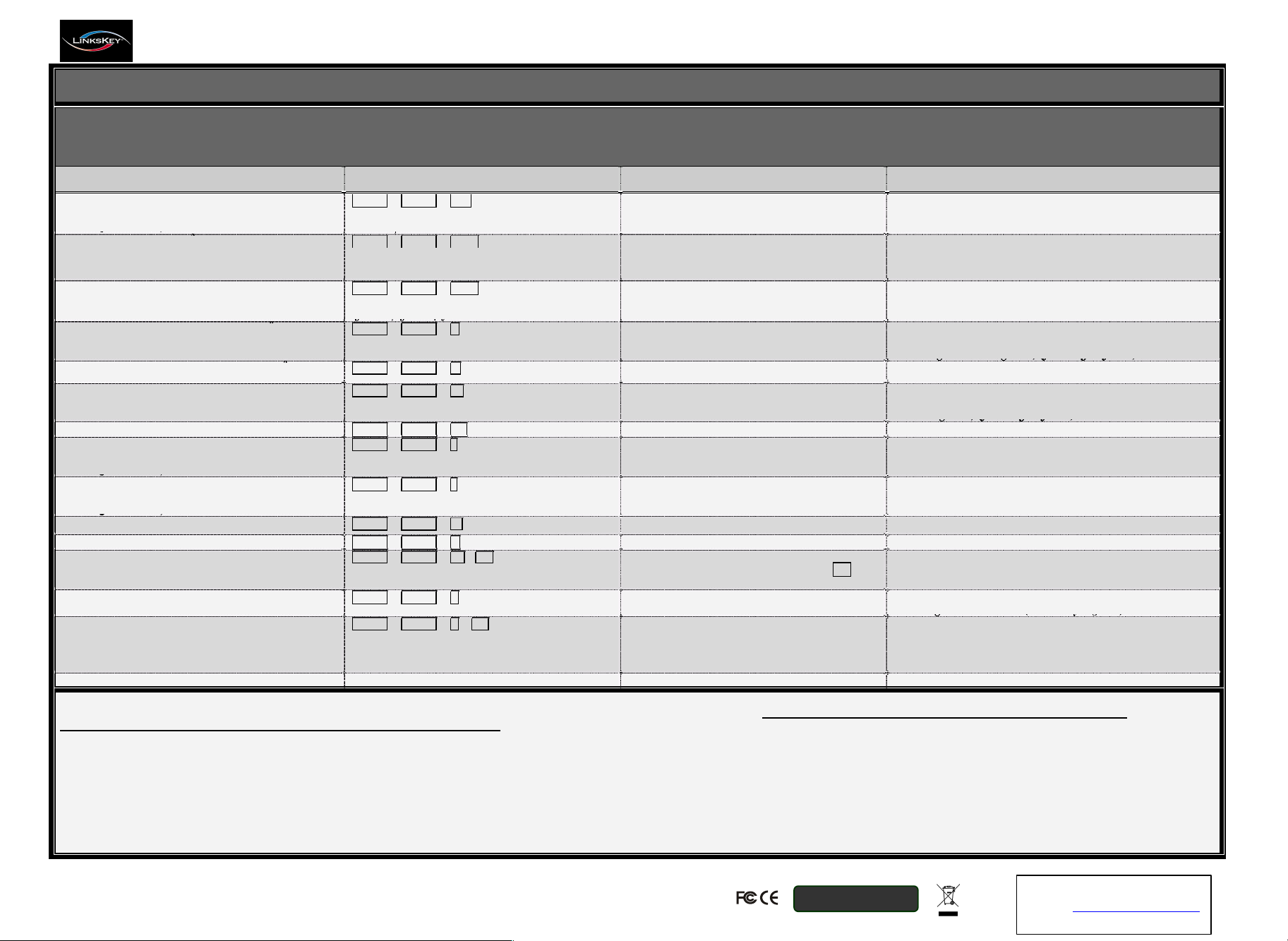
Q u i c k R e f e r e n c e S h e e t
2/4-port Dual Monitor DVI KVM Switch w/ Audio & Mic -- Operation Commands for Hotkeys / Front-Panel Buttons
Hotkey sequence = [ScrLk]* + [ScrLk] * + Command key(s) * User-definable Preceding sequence = SCROLL LOCK, CAPS, ESC, F12 or NUM LOCK
Command
Hotkeys
1
Front-panel Buttons
Description
Select PC Channel
2
(Joint-select PC port/hub port control/audio&mic,
if binding is enabled)
ScrLk + ScrLk + (x)
(x is a top-row number key)
x = 1~2 / x = 1~2 for PC channel no
Press the corresponding button to select the active
PC channel
Select the active PC channel
(Joint-select PC port/hub port control/audio&mic , if binding
is enabled)
Select Hub Port Control
2
(Joint-select PC & Hub port control, if binding is
enabled)
ScrLk + ScrLk + (Fx)
Fx = F1~F2 / Fx = F1~F4 ; Fx is a function key ;
x = 1~2/ x = 1~4 for PC channel no
(Press the corresponding button to select the
specific PC+USB hub port control --works only if
PC port/hub port control binding enabled)
Select the PC channel that control all USB hub ports
(Joint-select PC & Hub port control, if PC/hub port control
binding is enabled)
Select Audio&Mic Channel
4
(Joint-select PC port & audio/mic , if binding is
enabled)
ScrLk + ScrLk + (Fy)
Fy = F5~F6/ Fy = F5~F8 ; Fy is a function key ;
y = 1~2/ y = 1~4 for audio channel no
--
Select the active Audio&Mic channel
(Joint-select PC & audio&mic channel, if binding is enabled)
Bind PC & Hub Port Control Switching
2
[Default]
ScrLk + ScrLk + Z
--
Enable the binding of PC port and hub port control switching.
(Once this feature is enabled, any pc and/or hub port control
switching is bound together) (factory default)
Unbind PC & Hub Port Control Switching
2
ScrLk + ScrLk + X
--
Disable the binding of PC port and hub port control switching
Bind PC & Audio/Mic Switching
4
[Default]
ScrLk + ScrLk + Q
--
Enable the binding of PC port and audio&mic switching. (Once
this feature is enabled, any pc and/or audio&mic switching is
bound together) (factory default)
Unbind PC & Audio/Mic Switching
4
ScrLk + ScrLk + W
--
Disable the binding of PC port and audio&mic switching
Next lower PC channel
2
(Joint-select PC /hub port control/audio&mic,
if binding is enabled)
ScrLk + ScrLk + ↑ (arrow up)
--
Select the next lower connected PC channel
(Joint-select PC/hub port control/audio&mic, if binding is
enabled)
Next higher PC channel
2
(Joint-select PC /hub port control/audio&mic,
if binding is enabled)
ScrLk + ScrLk + ↓ (arrow down)
--
Select the next higher connected PC channel
(Joint-select PC/hub port control/audio&mic , if binding is
enabled)
Previous PC channel
ScrLk + ScrLk + (Backspace)
--
Toggle between the previous channel and current channel
Beep Sound On/Off
ScrLk + ScrLk + B
--
Toggle on/off the beep sound while autoscanning
Define Hotkey Preceding Sequence
ScrLk + ScrLk + H + (y)
y = SCROLL LOCK, CAPS, ESC,
F12 or NUM LOCK
Press and hold down last button (Button 2) till
two beeps, release the button, then press (y) key
Select the hotkey preceding sequence among 5 alternative keys
Autoscan
ScrLk + ScrLk + S
--
Autoscan through every connected channel for quick screen
browsing of each channel (scan delay = 5 sec.).
Autoscan with Programmable Delay Time
ScrLk + ScrLk + S + (z)
z = 0~9
1 10” ; 2 20” ; 3 30” ; 4 40” ; 5 50”
6 60” ; 7 70” ; 8 80” ; 9 90” ; 0 100”
--
Autoscan with a user-defined delay time within a range of
10 ~ 100 seconds
Stop Autoscan
Press any key on keyboard
Press any button
Terminate Autoscan activity
Notes:
1. The USB keyboard hotkeys allows you a faster and broader control for your KVM switching operation in addition to the front-panel buttons. If you have configured a hotkey preceding sequence other than two
consecutive scroll locks, you should change your hotkey sequence accordingly.(For preceding sequence key configuration, please refer to Quick Installation Guide)
2. When the binding of PC & USB hub port control switching is enabled by the hotkey sequence: ScrLk + ScrLk + Z, any PC and hub port control switching are bound together.
To remove this binding, use the hotkey sequence: ScrLk + ScrLk + X.
3. When the binding of PC & Audio&Micswitching is enabled by the hotkey sequence: ScrLk + ScrLk + Q, any PC and audio&mic switching are bound together.
To remove this binding, use the hotkey sequence: ScrLk + ScrLk + W.
LED Information: Green LED indicates PC port status: solid green – active port; flashing green – PC not connected; Red LED indicates hub port control status: solid red – that PC has the control of all hub ports.
Important Note: The USB hub control status LED (red) indicates not the connected status of each USB device, but indicates which PC port has the control of all hub ports and their connected devices.
For example, when USB LED 1 is lit, it means PC port 1 has the current control of all hub ports and their connected USB devices.
Technical Support
E-mail: btitech@linkskey.com
Website: www.linkskey.com
RoHS Compliant
Technical Support
E-mail: btitech@linkskey.com
Website: www.linkskey.com
Rev. 1.8 Copyright© All rights reserved
 Loading...