


L2201
&
L2202
User Manual
L2101 &L2102 Integrated Receiver Decoder Instruction Manual – Issue 1 – September 2003 Page i of 126
Tel: +44 (0) 1923 200 900 Customer Support and Service +44 (0) 1923 200 909
Link Research Ltd. 23 Watford Metro Centre, Dwight Road, Watford, Hertfordshire, WD18 9XA, England.
Registered in London No. 2074604 Web: www.linkres.co.uk Fax: +44 (0) 1923 241 357

INTRODUCTION
L2201 AND L2202 INTEGRATED RECEIVER DECODER
MANUAL SCOPE AND STRUCTURE
The User Manual for the L2201 and L2202 Integrated Receiver Decoders is comprised of
four main sections:
OVERVIEW:
This section provides introduction and product description, including highlights,
benefits and typical applications, gives a functional and physical description of the
unit and lists its main capabilities and specifications.
INSTALLATION:
This section provides data and procedures required to install and activate the unit.
Procedures include site preparation and requirements, installation in a 19" rack, cable
connections, panel options and Pin-out descriptions, initial settings and serviceability
check.
OPERATION:
This section provides theoretical background on the operation of the unit, and gives
data and instructions on using the unit and operating the control and monitoring
functions provided to the user.
MAINTENACE
It is assumed throughout this document that personnel have a general knowledge about
the L2201 and L2202 Integrated Receiver Decoders, application and capabilities.
L2101 &L2102 Integrated Receiver Decoder Instruction Manual – Issue 1 – September 2003 Page ii of 126
Tel: +44 (0) 1923 200 900 Customer Support and Service +44 (0) 1923 200 909
Link Research Ltd. 23 Watford Metro Centre, Dwight Road, Watford, Hertfordshire, WD18 9XA, England.
Registered in London No. 2074604 Web: www.linkres.co.uk Fax: +44 (0) 1923 241 357

After sales support
In all support requirements or in case of unit failure please contact Link Research directly (contact
details at the foot of this page). Always refer to the Link Research web site for firmware upgrades,
interoperability and support in general.
Standard war ra n ty cover
The L2101/L2102 Integrated Receiver Decoder is fully covered for parts and labour in case of failure
for one year from date of despatch from Link Research Ltd.
In addition an advance replacement service is includ ed for the first year, see below.
Extended warranty and advance replacement are available beyond the first year; contact Link
Research for details.
Repair procedure
If the unit has failed please contact Link to be given a RAN number (Return Authorisation Number).
Wherever possible please give a full description of the problem leading to the failure.
Return the unit to Link Research at the address given, preferably in the original packaging and
enclosing a full fault report wherever possible. The unit will be repaired and returned as soon as
possible. Repair times should be short but if you must have a replacement unit immediately then
you can take advantage of our advance repl acement service.
Advance replacement service
On request, once the fault has been discussed with a Link technician and a RAN number allocated,
Link Research will despatch a temporary replacement unit within 24 hours of your call. The
replacement unit must be returned on receipt of your repaired unit complete with the original
packaging.
N.B. For repairs and advance replacement units, shipping costs will be borne by Link Research for
the outward leg only.
For out-of-the box failures, occurring within the first 14 days from delivery, Link Research will pay
agreed transport costs in both directions.
CE Certification
Both L2201 and L2202 meet all the CE Class B requirements with the exception of
Emission Requirements.
In order to meet CE requirements, the following cables must be connected on all ASI
outputs (ASI out 1, ASI out 2, ASI out 3). When cables are connected to these outputs
then the device is compliant with FAIR-RITE 0443164151.
L2101 &L2102 Integrated Receiver Decoder Instruction Manual – Issue 1 – September 2003 Page iii of 126
Tel: +44 (0) 1923 200 900 Customer Support and Service +44 (0) 1923 200 909
Link Research Ltd. 23 Watford Metro Centre, Dwight Road, Watford, Hertfordshire, WD18 9XA, England.
Registered in London No. 2074604 Web: www.linkres.co.uk Fax: +44 (0) 1923 241 357

FCC Compliance Notice
Trade Name
Product Name Integrated Receiver Decoder
Product Model Number
Product Model Number
These devices comply with Part 15 of the FCC Rules.
Operation is subject to the following two conditions:
1. This device may not cause harmful interference.
2. This device must accept any interference received, including interference that may
cause undesired operation.
Responsible Party's Name
Address
Responsible Party's Telephone
Link Research
L2201
L2202
Roger Davies
Link Research Ltd
23 Watford Metro Centre
Dwight Road
Watford
Herts
WD18 9XA
United Kingdom
+44 1923 200900
The FCC Wants You to Know
This equipment has been tested and found to comply with the limits for a Class B digital
device, pursuant to Part 15 of the FCC rules. These limits are designed to Provide
reasonable protection against harmful interference in a residential installation. This
equipment generates, uses and can radiate radio frequency energy and, If not installed and
used in accordance with the instructions, may cause harmful interference to radio
communications.
However, there is no guarantee that interference will not occur in a particular installation. If
this equipment does cause harmful interference to radio or television reception, which can
be determined by turning the equipment off end on, the user is encouraged to try to correct
the interference by one or more of the following measures:
Reorient or relocate the receiving antenna.
Increase the separation between the equipment and receiver.
Connect the equipment to an outlet on a circuit different from that to which the receiver is
connected.
Consult the dealer or an experienced radio/TV technician.
FCC Warning
Modifications not expressly approved by the manufacturer could void the user authority to
operate the equipment under FCC Rules.
L2101 &L2102 Integrated Receiver Decoder Instruction Manual – Issue 1 – September 2003 Page iv of 126
Tel: +44 (0) 1923 200 900 Customer Support and Service +44 (0) 1923 200 909
Link Research Ltd. 23 Watford Metro Centre, Dwight Road, Watford, Hertfordshire, WD18 9XA, England.
Registered in London No. 2074604 Web: www.linkres.co.uk Fax: +44 (0) 1923 241 357

TABLE OF CONTENTS
Standard warranty cover............................................................................................iii
Repair procedure.......................................................................................................iii
Advance replacement service....................................................................................iii
1. Overview .................................................................................................................................. 9
1.1 General Information............................................................................................ 9
1.2 Highlights and Benefits....................................................................................... 9
1.3 Inputs ....................................................................................................... 10
1.4 Outputs............................................................................................................. 11
1.5 Conditional Access ........................................................................................... 11
1.6 Control And Monitoring..................................................................................... 12
1.7 Applications ...................................................................................................... 12
1.8 Broadcast Redistribution................................................................................... 13
1.9 Stand Alone Decoder........................................................................................ 13
1.10 Internal Corporate Distribution........................................................................ 13
1.11 Data Transfer.................................................................................................. 13
1.12 Low Speed Data............................................................................................. 14
1.13 High Speed Data ............................................................................................ 14
1.14 Descrambling.................................................................................................. 14
Functional Description ............................................................................................................ 15
1.15 L2201 and L2202 Block Diagram.................................................................... 15
1.16 Basic Configuration......................................................................................... 15
1.17 Receiver Front End Options............................................................................ 16
1.18 Configuration Options..................................................................................... 17
2 Mechanical Structure............................................................................................... 18
2.1 Enclosure ................................................................................................. 18
2.2 Front Panel............................................................................................... 18
2.3 Rear Panel ............................................................................................... 18
3 Management ........................................................................................................... 20
3.1 Front Panel Control .................................................................................. 20
3.2 Infrared Remote Control........................................................................... 20
3.3 PC Terminal Control................................................................................. 20
4 Characteristics and Specifications........................................................................... 21
4.1 Receiver Input Specifications ................................................................... 21
4.2 Output Specifications................................................................................ 23
4.3 Control Ports Specifications...................................................................... 24
4.4 Physical Features and Specifications ....................................................... 25
5 Installation........................................................................................................................................ 26
5.1 Introduction....................................................................................................................... 26
5.2 Safety Precautions ................................................................................... 26
5.3 Inventory Check ....................................................................................... 26
5.4 Site Preparation....................................................................................................... 27
5.5 Installation ............................................................................................................... 27
5.5.1 Installation in 19" Rack ............................................................................. 27
5.5.2 Insertion of the DVB-CI Module (PCMCIA)............................................... 28
5.6 Cable Connections .................................................................................................. 29
5.6.1 L2201 and L2202 Connection Setup and Options .................................... 29
5.6.2 Front End Panels...................................................................................... 30
5.6.3 Decoder Cable Connections..................................................................... 30
5.6.4 Terminal Control and Data Connections................................................... 30
5.6.5 Power Connection.................................................................................... 31
Ground Connection .................................................................................. 31
AC Power Connector................................................................................ 32
DC Power Connector................................................................................ 32
L2101 &L2102 Integrated Receiver Decoder Instruction Manual – Issue 1 – September 2003 Page v of 126
Tel: +44 (0) 1923 200 900 Customer Support and Service +44 (0) 1923 200 909
Link Research Ltd. 23 Watford Metro Centre, Dwight Road, Watford, Hertfordshire, WD18 9XA, England.
Registered in London No. 2074604 Web: www.linkres.co.uk Fax: +44 (0) 1923 241 357

5.7 System Expansion................................................................................................... 33
5.7.1 Cascade Loopthrough Output................................................................... 33
5.7.2 ASI Loopthrough Cascade ....................................................................... 33
5.7.3 RS-485 Master-Slave Connection ............................................................ 34
5.8 Initialization And Configuration ................................................................................ 35
5.8.1 Powering Up............................................................................................. 35
5.8.2 Initialization Sequence.............................................................................. 35
5.8.3 Serviceability Check ................................................................................. 38
6 Operation ......................................................................................................................................... 39
6.1 Introduction....................................................................................................................... 39
6.1.1 IRD Operation and Management.............................................................. 39
6.1.2 Front Control Panel ......................................................................... 40
6.1.3 Infrared Remote Control (Optional).................................................. 41
6.2 Four Way Touch Pad.......................................................................... 43
6.3 Front Panel Common Main Menu Options................................................ 44
6.4 Configuration Menu ................................................................................................. 46
6.5 Configuration / Receiver Menu ................................................................. 47
6.5.1 Configuration / Decoder Menu.................................................................. 53
Decoder / Stream Configuration Sub-Menu.............................................. 55
6.5 Decoder/CI Configuration Sub-Menu.................................................. 58
6.6 Decoder / Video Configuration Sub-Menu .......................................... 59
6.7 Decoder / Audio Configuration Sub-Menu .......................................... 62
6.8 Configuration/System Menu ..................................................................... 64
6.9 Status Menu ............................................................................................................ 68
6.9.1 Status / Receiver Menu ............................................................................ 69
6.9.2 Status / Decoder Menu............................................................................. 73
6.10 Decoder / Stream Status Sub-Menu ................................................. 75
6.11 Decoder / CI Status Sub-Menu......................................................... 78
Decoder / Video Status Sub-Menu ........................................................... 80
6.12 Decoder / Audio Status Sub-Menu ................................................... 82
6.12 Status / System Menu .............................................................................. 84
6.13 Test Menu ............................................................................................................... 84
6.14 Run Menu................................................................................................................ 87
6.15 Run / Service Menu.................................................................................. 88
6.16 Run / PID Menu........................................................................................ 91
6.17 Mode Run Menu....................................................................................... 93
6.18 Advance Run Menu.................................................................................. 96
6.19 Graphics Configuration (GFX-CNFG) Sub-Menu.............................. 97
Graphics Display (GFX-DSPL) Sub-Menu.............................................. 100
6.19 Other Advance Run Sub-Menu....................................................... 106
7 Maintenance................................................................................................................................... 107
7.1 General........................................................................................................................... 107
7.2 Safety Instructions................................................................................................. 107
7.2.1 Safety Precautions ................................................................................. 107
7.2.2 Caution and Warning Statements........................................................... 107
7.3 Test Procedures .................................................................................................... 108
7.3.1 Power-Up Check. ................................................................................... 108
7.3.2 Maintenance Check Serviceability Check............................................... 108
7.3.3 Audio/Video Stream Test........................................................................ 108
7.4 Common Status Messages.................................................................................... 109
7.4.1 General Status Messages ...................................................................... 109
7.4.2 Hardware Failure Messages................................................................... 110
7.4.3 BIT Stream Warning Messages.............................................................. 111
7.4.4 Service Warning Messages.................................................................... 112
Appendix A. Appendix 1: Operational Menu Trees ................................................................... 122
Appendix B. Appendix B: LNB Theory Of Operation................................................................. 123
L2101 &L2102 Integrated Receiver Decoder Instruction Manual – Issue 1 – September 2003 Page vi of 126
Tel: +44 (0) 1923 200 900 Customer Support and Service +44 (0) 1923 200 909
Link Research Ltd. 23 Watford Metro Centre, Dwight Road, Watford, Hertfordshire, WD18 9XA, England.
Registered in London No. 2074604 Web: www.linkres.co.uk Fax: +44 (0) 1923 241 357

B.1 Why is an LNB needed? ....................................................................................................... 123
B.3 Frequency Calculation IRD + LNB........................................................................................ 123
B.4 Use of a Splitter or Distribution (band) Amplifier ................................................................... 124
B.5 Calculating the L-Band Frequency........................................................................................ 125
D.1 Calculating Symbol Rate ...................................................................................................... 126
L2101 &L2102 Integrated Receiver Decoder Instruction Manual – Issue 1 – September 2003 Page vii of 126
Tel: +44 (0) 1923 200 900 Customer Support and Service +44 (0) 1923 200 909
Link Research Ltd. 23 Watford Metro Centre, Dwight Road, Watford, Hertfordshire, WD18 9XA, England.
Registered in London No. 2074604 Web: www.linkres.co.uk Fax: +44 (0) 1923 241 357


1. Overview
1.1 General Information
The L2201 and L2202 are a new generation of the 4:2:0 / 4:2:2 Integrated Receiver
Decoders. Both L2201 and L2202 are suitable for SCPC and MCPC 4:2:0 applications;
L2202 provides support for 4:2:2 applications as well. With DVB-CI (Common Interface)
decryption capabilities, the IRD 2600 and L2202 output high quality video, audio and data
for satellite, cable and telecom programme distribution. L2201 supports two stereo outputs
while L2202 supports up to three stereo outputs.
Both L2201 and L2202 contain a demultiplexer, MPEG-2 video and audio decoders, as well
as Data and VBI insertion functions.
Control and management can be obtained via the IRD front control panel, an optional
Infrared Remote Control, or an attached PC terminal.
Input and Output sections support variable modules for versatility of the L2201 and L2202.
Input of DVB-ASI transport Stream or RS-422 directly to the decoder, as well as ASI output
(optionally decrypted) and loopthrough is also supported. ASI TS and RS-422 can be
connected at the same time with the various front ends. The desired input is selected by
the user.
L2201 and L2202 - General View
1.2 Highlights and Benefits
The L2201 and L2202 Integrated Receiver Decoders provide the following benefits:
• DVB Common Interface (2 Slots), Supports de-scrambling of all leading CAMs
• On-board DVB descrambling with BISS Mode-1 and BISS-E (DSNG-CA) support.
• Extended Front/End Interface options
• High and Low Speed Data Outputs
• Advanced software control and monitoring of all IRD functions and capabilities.
The following sub-paragraphs detail the features, enhancements and options of the L2201
and L2202.
L2101 &L2102 Integrated Receiver Decoder Instruction Manual – Issue 1 – September 2003 Page 9 of 126
Link Research Ltd. 23 Watford Metro Centre, Dwight Road, Watford, Hertfordshire, WD18 9XA, England.
Tel: +44 (0) 1923 200 900 Customer Support and Service +44 (0) 1923 200 909
Registered in London No. 2074604 Web: www.linkres.co.uk Fax: +44 (0) 1923 241 357

1.3 Inputs
Decoder Inputs RS-422 Clock/Data Input
DVB-ASI with Loop-through (optional)
Receiver Input Options DVB Satellite (QPSK) Front End
DVB DSNG (8PSK, 16QAM and QPSK) Front End
• Interface: Copper or Optical
• TS bit rate: up to 54 Mbps
• Frequency range: 950 -2150 MHz
• Symbol rate range: 1 - 45 M Symbols/s
• L-Band RF input with LNB control and
Loop-through output
•
• Frequency Range: 950-2150 MHz
• Symbol rate Range: 1 -45 Msym/s
• 2 L-Band inputs with LNB control
L2101 &L2102 Integrated Receiver Decoder Instruction Manual – Issue 1 – September 2003 Page 10 of 126
Tel: +44 (0) 1923 200 900 Customer Support and Service +44 (0) 1923 200 909
Link Research Ltd. 23 Watford Metro Centre, Dwight Road, Watford, Hertfordshire, WD18 9XA, England.
Registered in London No. 2074604 Web: www.linkres.co.uk Fax: +44 (0) 1923 241 357

1.4 Outputs
Video
VBI Re-Insertion
Audio
Data
Transport Stream Outputs
(options)
• Analog video Interfaces: 2 composite, 1 S-Video
• Digital video Interfaces (optional):
2x SDI, with embedded VBI and up to 2 stereo
channels
• Video formats:
PAL-B/G/I/M/N/D, NTSC/SECAM L/B/G/K1
• Russian SECAM D/K (option applicable only in
composite video, available only for L2201).
• Decoding:
4:2:0MP@ML (1.5 -15 Mbps)
4:2:2PP@ML (1.5 -50 Mbps) (L2202)
• Video Resolution Interpolation:
Pan-Scan, Letter box or Pass-through
• Aspect ratio:4:3/16:9 and 14:9
• Graphic processing: OSD, DVB Subtitling,
EBU (Teletext) Subtitling.
• OSD only on monitoring output (optional)
• Sync Lock Input and Loopthrough output (optional)
•
• In Composite video and embedded in SDI
• WST Teletext and inverted Teletext
• WSS, VPS, VITC, SMC, CC, AMOL (optional)
• Enhanced VITS with built-in generator
•
• Analog audio: up to 3 stereo pairs (up to 2 stereo
pairs in L2201). All inputs balanced or 1st
unbalanced (optional)
• Digital audio (optional): up to 3 AES/EBU-SPDIF
(up to 2 on L2201)
• Embedded in SDI (optional): up to 2 stereo
• Mode: Stereo, Joint Stereo, Dual Channel, Single
Channel
• Max output level: +24 dBu analog, 0 dBFs digital
• Gain Control: -58 to +6 dB /mute
• AC-3 Pass-through (optional)
• Low Speed Data:
RS-232 up to 115.2 Kbaud, or
RS-422 (optional) up to 2Mbps
• High Speed Data: RS-422 up to 20 Mbps
• 1st and 2nd ASI (optional): Copper, or Input stream
with selected program decrypted
• 3rd ASI (optional): Copper or Optical ,Input stream
or Loop-through
1.5 Conditional Access
DVB-Descrambling
L2101 &L2102 Integrated Receiver Decoder Instruction Manual – Issue 1 – September 2003 Page 11 of 126
Link Research Ltd. 23 Watford Metro Centre, Dwight Road, Watford, Hertfordshire, WD18 9XA, England.
Tel: +44 (0) 1923 200 900 Customer Support and Service +44 (0) 1923 200 909
Registered in London No. 2074604 Web: www.linkres.co.uk Fax: +44 (0) 1923 241 357
• BISS Mode-1
• BISS-E

DVB-CI
1.6 Control And Monitoring
Local
General Purpose Indicator
(GPI)
Over The Air
Remote
Enhanced DVB Monitoring
• Interface:2 CI slots – EN—50221
• CA Method: Multicrypt, Simulcrypt
• CAS: Irdeto
Aston
BetaCrypt
®
, Viaccess®, Cryptoworks®, Conax®,
®
, Nagravision®, On Digital®, CODICrypt ®,
®
, NDS VideoGuard®
• Extensive Front Panel Control
• Infrared remote control (optional)
• Up to 140 stored setups (optional for 340)
• Advanced satellite scanning
• Can operate in Service and in PID modes
GPI dry contacts for various alarms and automatic
redundancy features. Supports combination of the
following alarm modes:
• Activated when hardware failure is identified
(default alarm mode).
• Activated when Bit Stream warning is identified
(i.e. input signal failure).
• Activated when Service Decoding warning is
identified.
• Mode selection is manually activated, using the
control protocol.
• Control and Software download
• PC via RS-232 or RS-485
• Software download
• SNMP proxy PC software (optional)
• Front panel display: Signal Quality, Eb/N0, BER,
ASI format, Network and Service Information,
CA information, CI slots, Video and Audio
decoded information
1.7 Applications
The L2201 and L2202 Integrated Receiver Decoders can be implemented in a wide range
of applications. The following is a list of some of the typical uses for the L2201 and L2202:
• Satellite Receiving
• Cable Head-end Receiving
• Digital Satellite News Gathering (DSNG)
• Telecommunication, SDH or microwave
• Network / Professional Video Distribution
• Distance Learning
• Business TV
• Radio Reception
• DVB-CI Decryption for transport stream re-multiplexing
L2101 &L2102 Integrated Receiver Decoder Instruction Manual – Issue 1 – September 2003 Page 12 of 126
Link Research Ltd. 23 Watford Metro Centre, Dwight Road, Watford, Hertfordshire, WD18 9XA, England.
Tel: +44 (0) 1923 200 900 Customer Support and Service +44 (0) 1923 200 909
Registered in London No. 2074604 Web: www.linkres.co.uk Fax: +44 (0) 1923 241 357
• OSD: PSI tables, Receiver and Decoder status
information

• Bilingual audio transmission
The following paragraphs provides detailed description on various applications.
1.8 Broadcast Redistribution
The primary application of the L2201 and L2202 is reception and distribution of DVB
broadcast signals for cable or local broadcasting.
1.9 Stand Alone Decoder
The L2201 and L2202 may be utilized without an input receiver as an online decoder for a
DVB signal. This may be utilized for monitoring purposes within a broadcast center, for
editing components of the DVB bit stream, and for redistribution of local line input such as
prerecorded video programs.
1.10 Internal Corporate Distribution
A growing application for DVB redistribution is internal corporate training and
communications. Both training and internal communications can greatly benefit from the
decoding and redistribution of DVB signals originating from a central broadcast point within
a company.
1.11 Data Transfer
The L2201 and L2202 can be implemented as a solution for remote locations requiring data
links, where no proper line communications exist. In this role, the L2201 and L2202
decodes data from a DVB signal broadcast via satellite or other Telco interfaces.
One of the advanced features of the L2201 and L2202 is simultaneous high-speed and
low-speed data transfer. Data transfer from the encoder is uni directional. The L2201 and
L2202 has no feedback, response, or acknowledgement capabilities.
L2101 &L2102 Integrated Receiver Decoder Instruction Manual – Issue 1 – September 2003 Page 13 of 126
Tel: +44 (0) 1923 200 900 Customer Support and Service +44 (0) 1923 200 909
Link Research Ltd. 23 Watford Metro Centre, Dwight Road, Watford, Hertfordshire, WD18 9XA, England.
Registered in London No. 2074604 Web: www.linkres.co.uk Fax: +44 (0) 1923 241 357

1.12 Low Speed Data
The L2201 and L2202 enable Low Speed Data (LSD) transfer rates up to 115.2 Kbps over
a serial RS-232 port. The LSD interface supports filtering of the data encapsulated in PES
packets (stream types “0xBD”-private_stream_1 and “0xBF”-private_stream_2). In addition,
data filtering level can be according DVB Asynchronous Data streaming (EN 301 192)
which includes additional 3 bytes of header information in front of the data information.
The following filtering levels are provided:
• Entire Transport Packet
• Transport Payload (184 bytes if no adaptation field, else adaptation is also stripped).
• PES payload (PES header stripped).
• DVB streaming (PES header and 3 byte pes_data_packet header stripped).
1.13 High Speed Data
a. The L2201 and L2202 enable High Speed Data (HSD) transfer rates up to 20
Mbps over a balanced RS-422 port. The high-speed transfer rates are limited by the
maximum rate supported by the RS-422 interface and cable lengths.
b. IRD HSD rates should be set slightly higher than those on the encoder (5%
higher). Optimal rate is best determined by trial and error. Too low a rate yields
increased bit errors. Conversely, too high a rate yields a stream that is too bursty. This
is not a problem if the target equipment (usually a PC) has a large enough buffer to
compensate for incidental burst size. To adapt the L2201 and L2202 to work with a
variety of encoders, bit-order can be reversed.
c. The following packetizing methods of data are provided:
• Entire Transport Packet
• Transport Payload (184 bytes if no adaptation field, else adaptation is also
stripped).
• PES payload (PES header stripped).
1.14 Descrambling
The L2201 and L2202 are equipped with internal DVB descrambler and two independent
DVB-CI Common Interface slots.
The internal DVB Descrambler is usable for:
• DSNG-CA (BISS) fixed Key Encryption system and BISS-E.
The DVB-CI deciphers encrypted signals from a DVB signal source, by means of an
authorized Smart Card and a CA-specific CAM (Conditional Access Module).
The encryption standards supported by the L2201 and L2202 are:
• CA Method: Multicrypt, Simulcrypt
• CAS: Irdeto
CODICrypt
®
, Viaccess®, Cryptoworks®, Conax®, Aston ®, Nagravision®, On Digital®,
®
, BetaCrypt®, NDS VideoGuard®.
L2101 &L2102 Integrated Receiver Decoder Instruction Manual – Issue 1 – September 2003 Page 14 of 126
Tel: +44 (0) 1923 200 900 Customer Support and Service +44 (0) 1923 200 909
Link Research Ltd. 23 Watford Metro Centre, Dwight Road, Watford, Hertfordshire, WD18 9XA, England.
Registered in London No. 2074604 Web: www.linkres.co.uk Fax: +44 (0) 1923 241 357

Functional Description
1.15 L2201 and L2202 Block Diagram
Input to the Receiver (DSNG receiver, QPSK, QAM) is transferred to the de-multiplexer in
the MPEG-2 Transport Demux. A video decoder and an audio decoder process the
resulting video, audio and data streams.
The end output is modified to suit the required output formats according to the installed
output modules.
A dedicated VBI programmable processor is assigned for providing various customers VBI
requirements.
Signal Paths in the L2201 and L2202
Out 1
Out 2
Out 3
Loopthrough
Input Signal
ASI
Interface
SYNC
ASI
VIDEO
DECODER
PAL/NTSC
ENCODER
VIDEO
AMP.
TELETEXT
INPUT SECTION
DSNG,QPSK, QAM
TRANSPORT
OPTIONS
OUT
(OPTION)
RECEIVER
Input Signal
CI
MPEG-2
DEMUX
TELETEXT
TRANSCODER
OUTPUT
GPI
Smart Card
AES/EBU
OUTPUT
(OPTION)
AUDIO
DECODER
D/A
CONVERTER
AUDIO
AMP.
AUDIO OUTVIDEO OUT
GPI
Interface
CPU
Data
Processor
DATA CHANNEL
(RS-232/RS-422)
1.16 Basic Configuration
The L2201 and L2202 are delivered in a wide range of standard configurations, as
described in paragraph 0 below. Paragraph 0 describes the add-on options available for
the various configurations.
However, all L2201 / L2202 configurations provide the following basic features:
Front Panel
(Display &
Keyboard)
• Profile: 4:2:0 (4:2:2 for L2202 only)
• 2 slots DVB-CI Common Interface
• Video formats: PAL B/G/M/N/D, NTSC, SECAM L/B/G/K1
• Transcoding of 625/50 video formats (PAL B/G to/from PAL N and SECAM) and of
525/60 video formats (PAL M to/from NTSC)
• Two Composite outputs; One S-VHS output
L2101 &L2102 Integrated Receiver Decoder Instruction Manual – Issue 1 – September 2003 Page 15 of 126
Link Research Ltd. 23 Watford Metro Centre, Dwight Road, Watford, Hertfordshire, WD18 9XA, England.
Tel: +44 (0) 1923 200 900 Customer Support and Service +44 (0) 1923 200 909
Registered in London No. 2074604 Web: www.linkres.co.uk Fax: +44 (0) 1923 241 357

• Full DVB compliance, as well as special modes for interoperability with certain
non-DVB IRDs
• Audio (1st channel): one stereo pair, balanced output via XLR connectors; volume
adjustment.
• Data channel: High-Speed Data @ RS-422 and Low-Speed Data @ RS-232
• DVB descrambling, SimulCrypt Support, BISS DSNG-CA
• Over the air remote control; Over the air software upgrade
• Teletext, VBI (WSS, Close Caption, VPS, VITS, VITC, SMC), analog, over composite
• Selectable Audio/Video/Data combination mode OR Video-only OR Data-only OR
Audio-only mode.
• Monitor and Control via RS-232 or RS-485 terminal (factory pre-set).
• Auto-save of last configuration after power off; 140 pre-programmed setups (optional:
340).
• Front panel control; Extensive Status indicators; Signal quality (Eb/N0), Video/Audio
rate, CA information.
• RS-422 transport stream input
1.17 Receiver Front End Options
The L2201 / L2202 are delivered in various front-end configurations. The following defines
the specific features of each configuration, in addition to the basic features described
above.
DVB-S QPSK Receiver Front-End Option:
• QPSK receiver for full bandwidth (SCPC/MCPC) operation at agile
1-45 MSymbols/sec,
• L-BAND input and RF Loop-through
DVB-C QAM Receiver Front-End Option:
• 16/32/64/128/256 QAM receiver for SCPC & MCPC operation at agile
1 - 7 MSymbols/Sec
• VHF/UHF input and Loop-through.
Decoder Standard Unit (RS-422 input):
• For ASI Input, refer to options.
• DS3 or E3 framed interface and Loop-through, (back to back ATM protocol, AAL1).
DVB-DSNG 8PSK, 16QAM and QPSK Receiver Front-End Option:
• 8PSK, 16QAM and QPSK receiver for full bandwidth (SCPC/MCPC) operation at
agile 1-45 Msymbols/sec
• 2 x L-Band inputs (950-2150 MHz)
The IRD also supports an option of 2 inputs with loop through of the selected input, with
automatic redundancy switching between inputs A & B, for the following input end options:
DVB-S, DVB-C, G.703, DVB-PDH.
Time between switching is controlled.
L2101 &L2102 Integrated Receiver Decoder Instruction Manual – Issue 1 – September 2003 Page 16 of 126
Tel: +44 (0) 1923 200 900 Customer Support and Service +44 (0) 1923 200 909
Link Research Ltd. 23 Watford Metro Centre, Dwight Road, Watford, Hertfordshire, WD18 9XA, England.
Registered in London No. 2074604 Web: www.linkres.co.uk Fax: +44 (0) 1923 241 357

1.18 Configuration Options
The following table lists the configuration options available for the various L2201/L2202
Standard applications:
NAME DESCRIPTION
Russian Secam Russian Secam, on the broadcast output only. (Built-in with
OPT 006) Available only for L2201.
-48V DC -48V DC power interface (Replacing the 110-230V AC)
BISS 1 & E for ASI out For supporting decryption of the slected service over the ASI
Transport Stream output.
L2101 &L2102 Integrated Receiver Decoder Instruction Manual – Issue 1 – September 2003 Page 17 of 126
Tel: +44 (0) 1923 200 900 Customer Support and Service +44 (0) 1923 200 909
Link Research Ltd. 23 Watford Metro Centre, Dwight Road, Watford, Hertfordshire, WD18 9XA, England.
Registered in London No. 2074604 Web: www.linkres.co.uk Fax: +44 (0) 1923 241 357

2 Mechanical Structure
2.1 Enclosure
The L2201 and the L2202 are housed in a ruggedized industrial enclosure, 1U by 19"
(Rack Mount).
2.2 Front Panel
The front panel of the L2201 and L2202 allow control via a four-way touch pad, an Enter
key, and an Escape key. Operational commands and parameters are displayed on an
Alphanumeric LCD. The four-way touch pad allows scrolling through the menus of the
embedded software and parameter modification.
Front View of the L2201/L2202
2.3 Rear Panel
The rear panel of the IRD L2201 and L2202 are comprised of three sections
• Front-End Options section (left side of the rear panel)
• Decoder section (center)
• Option section (right side)
Left and right sections support various modules to enhance the versatility of the
L2201 and L2202 in varied applications. They support input of Parallel DVB Transport
Stream, Parallel TTL, DVB ASI, or RS-422 serial input. This option enables input directly to
the Decoder where the signal source is digital or when input via a receiver is not required.
The Decoder contains a demultiplexer, MPEG-2 video and audio decoders as well as a
Teletext Transcoder module for Teletext output. The Decoder section on the rear panel is
standard. However, digital and analog audio options are available.
The figure below shows two examples of L2201 and L2202 rear panel configurations.
Example A shows the Decoder configured for output over RCA connectors. Example B
shows the XLR alternative.
L2201/L2202 Rear Panel Section
Example A
ASI
ASI
OUT 1
OUT 2
RF IN
- 25dBmMax OUT
LOOPTHROUGH
Example B
ASI
ASI
OUT 1
OUT 2
RF IN
- 25dBmMax OUT
LOOPTHROUGH
Table 1-1: L2201/L2202 Output Option
OPTION CARD DESCRIPTION
L2101 &L2102 Integrated Receiver Decoder Instruction Manual – Issue 1 – September 2003 Page 18 of 126
Link Research Ltd. 23 Watford Metro Centre, Dwight Road, Watford, Hertfordshire, WD18 9XA, England.
Tel: +44 (0) 1923 200 900 Customer Support and Service +44 (0) 1923 200 909
Registered in London No. 2074604 Web: www.linkres.co.uk Fax: +44 (0) 1923 241 357
RS422/GPI
RS422/GPI
LEFT
RIGHT
AUDIO
LEFT1 RIGHT1
ANALOG AUDIO OUT
AES/EBU
AC3
S-VIDEO
AES/EBU
AC3
S-VIDEO
[]
[]
AES/EBU1
[]
LEFT2
BALANCED AUDIO ASI SYNC LOCK SDI OUT
AES/EBU2
[]
RIGHT2
OUT3OUT 1
IN IN 2
100-240VAC 1A
50/60 Hz
100-240VAC 1A
50/60 Hz

Table 1-1: L2201/L2202 Output Option
OPTION CARD DESCRIPTION
BLANK OUTPUT PANEL
This panel is supplied as default when no
output option is ordered.
LEFT2 RIGHT2
BALANCED AUDIO OUT
LEFT2 RIGHT2
BALANCED AUDIO OUT
LEFT3 RIGHT3
Full With ASI In and OUT 3
Balanced Analog Audio over XLR or
AES/EBU (SP-DIF) over XLR
ASI IN + OUT Loopthrough
Sync lock IN + OUT
SDI OUT 1 + 2
Balanced Analog Audio 2 Out over XLR
Balanced Analog Audio 2 and 3 Out over
XLR
(Applicable Only for L2202)
Full With ASI OUT 1 + 2
L2101 &L2102 Integrated Receiver Decoder Instruction Manual – Issue 1 – September 2003 Page 19 of 126
Link Research Ltd. 23 Watford Metro Centre, Dwight Road, Watford, Hertfordshire, WD18 9XA, England.
Tel: +44 (0) 1923 200 900 Customer Support and Service +44 (0) 1923 200 909
Registered in London No. 2074604 Web: www.linkres.co.uk Fax: +44 (0) 1923 241 357

3 Management
The L2201 and L2202 Integrated Receiver Decoder contain embedded software for control
and configuration. The embedded software is accessible by the following interfaces:
• L2201/L2202 Front Panel
• Infrared Remote Control
• PC terminal
3.1 Front Panel Control
The L2201 and L2202 Front Panel provide a two line LCD display and a control keys. It
enables the user to control and monitor the L2201 and L2202.
3.2 Infrared Remote Control
The infrared remote control device supplied with the L2201 and L2202 enables arm chair
control of the L2201 and L2202. The control keys are similar to those on the L2201 and
L2202 Front Panel in order to provide a common interface and control syntax.
3.3 PC Terminal Control
The L2201 and L2202 may be controlled and configured from a standard PC terminal
attached to the Control (RS-232 or RS-485) connector. The terminal provides access to
control and monitor functions not available when using the L2201 and L2202 Front Panel or
the infrared remote control.
L2101 &L2102 Integrated Receiver Decoder Instruction Manual – Issue 1 – September 2003 Page 20 of 126
Tel: +44 (0) 1923 200 900 Customer Support and Service +44 (0) 1923 200 909
Link Research Ltd. 23 Watford Metro Centre, Dwight Road, Watford, Hertfordshire, WD18 9XA, England.
Registered in London No. 2074604 Web: www.linkres.co.uk Fax: +44 (0) 1923 241 357

4 Characteristics and Specifications
4.1 Receiver Input Specifications
The following tables summarize the features and specifications of the various receiver input
options available for the L2201 and the L2202 Integrated Receiver Decoder:
• QPSK input option,
• DNSG input option,
• QAM input option,
QPSK Input Features and Specifications
FEATURE SPECIFICATION
L-Band input 950-2150 MHz
L-Band Loopthrough output 950 – 2150 MHz ± 3dB
Input level -65 to –25 dBm
Symbol Rate 1 - 45 Msymbols/sec continues
Symbol Rate acquisition
range
Carrier acquisition range
BER (Quasi Error Free after
Reed Solomon)
Viterbi Decoding Rates 1/2, 2/3, 3/4, 4/5, 5/6, 7/8, 8/9
Viterbi Constraint Rate 7
Viterbi Rate Recovery Automatic
Reed Solomon decoding 204, 188,
De-interleaving Yes
Digital AGC Yes
LNB Control Voltage: Off, 14V, 18V, (350 mA maximum)
Polarization 22 kHz/Off
Spectral Inversion Automatic
± 70 ppm
± 1/4 Symbol Rate
2 x 10⁻⁴ for Eb/No = 5.5 dB, after Viterbi 3/4
L2101 &L2102 Integrated Receiver Decoder Instruction Manual – Issue 1 – September 2003 Page 21 of 126
Tel: +44 (0) 1923 200 900 Customer Support and Service +44 (0) 1923 200 909
Link Research Ltd. 23 Watford Metro Centre, Dwight Road, Watford, Hertfordshire, WD18 9XA, England.
Registered in London No. 2074604 Web: www.linkres.co.uk Fax: +44 (0) 1923 241 357

DSNG Input Features and Specifications
FEATURE SPECIFICATION
Modulation and coding schems:
QPSK, FEC rate
8PSK, FEC rate
16QAM, FEC rate
Automatic modulation scheme
recovery
Symbol Rate 1 ≤ Rs ≤ 45 Mbaud
Half Nyquist filter roll-off 25% and 35%
L-band inputs (950–2150 MHz) 2
Signal level density Co -130 to –105 dBm/Hz.
Signal level Co + 10Log(Sat. baud rate) (dBm).
Total input power -25 dBm max
Clock acquisition range
carrier acquisition range
Automatic FEC rate recovery
Spectral inversion ambiguity
resolution
LNB power generation Off, 13 or 18 Vdc, 350 mA max, 22Khz,
1/2, 2/3, 3/4, 5/6, 7/8.
2/3, 5/6, 8/9.
3/4, 7/8.
± 200 ppm
± 3 Mhz
Automatic
single tone burst and Diseqc 1.0 message,
and Diseqc 2.0 compatible
QAM Input Features and Specifications
FEATURE SPECIFICATION
QAM constellation 16/32/64/128/256 QAM
Input Level
VHF/UHF input 50.5 to 858 MHz
Noise Figure 8 to 13 dB
Input impedance
Symbol Rate 1 to 7 Mbaud
Roll-off 15%
Additional Features Digital Automatic Gain Control
L2101 &L2102 Integrated Receiver Decoder Instruction Manual – Issue 1 – September 2003 Page 22 of 126
Link Research Ltd. 23 Watford Metro Centre, Dwight Road, Watford, Hertfordshire, WD18 9XA, England.
Tel: +44 (0) 1923 200 900 Customer Support and Service +44 (0) 1923 200 909
Registered in London No. 2074604 Web: www.linkres.co.uk Fax: +44 (0) 1923 241 357
40 to 85 dBµV
75Ω (BNC)
Half Nyquist Filtering
Blind equalization
Digital carrier recovery

4.2 Output Specifications
The following tables summarize the features and specifications of the L2201 and the L2202
Video and Audio outputs, respectively.
Video Decoder Output Features and Specifications
FEATURE SPECIFICATION
MPEG-2 standard Main Level at Professional Profile, and
Standards decoded MPEG-1, MPEG-2
Decoded Output Resolution
Encoded Input Resolution of
the L2201
Encoded Input Resolution of
the L2202
Video Encoder 27 MHz with 10 bits resolution DAC (8 bits input)
Video formats decoded NTSC / PAL / SECAM standards and sub-standards
Video formats selection Automatic selection for NTSC / PAL
Standard Outputs 2 Composite Video outputs
Main Level at Main Profile
• 720 by 480 at 30 Hz (NTSC)
• 720 by 576 at 25 Hz (PAL)
[Horizontal] by [Vertical] at [Frequency]
720, 704, 640,
544, 528, 480,
352, 320
720, 704, 640,
544, 528, 480,
352, 320
352 240 30 Hz
384, 352 240 24 Hz
720, 704, 640,
544, 528, 480, 352
720, 704, 640,
544, 528, 480, 352
[Horizontal] by [Vertical] at [Frequency]
720, 704, 544,
480, 352
352 240 30 Hz
720, 704, 544,
480, 352
352 288 25 Hz
4:2:2 Mode Only
720 512 30 Hz
720 608 25 Hz
S-Video (Y/C) output
480 30 Hz
480 24 Hz
576 25 Hz
288 25 Hz
480 30 Hz
576 25 Hz
L2101 &L2102 Integrated Receiver Decoder Instruction Manual – Issue 1 – September 2003 Page 23 of 126
Tel: +44 (0) 1923 200 900 Customer Support and Service +44 (0) 1923 200 909
Link Research Ltd. 23 Watford Metro Centre, Dwight Road, Watford, Hertfordshire, WD18 9XA, England.
Registered in London No. 2074604 Web: www.linkres.co.uk Fax: +44 (0) 1923 241 357

Audio Output Features and Specifications
FEATURE SPECIFICATION
Quality CD Quality 16 bit delta – sigma DAC
Sample rates 48 KHz, 44.1 KHz, 32 KHz, 24 KHz, 22.05 KHz, 16 KHz
Decoding Levels
• MPEG-2 Stereo
• MPEG-1 layer I and II
• AC-3 Dolby Digital Surround
®
pass-through
• Linear Audio on digital output (L2202 Only)
Audio 1 Channel
• Balanced Stereo
• Unbalanced Mono/Stereo (option)
• AES/EBU (SP-DIF, option)
Audio 2 Channel (option)
• Balanced Stereo (option)
• AES/EBU (SP-DIF, option)
Audio 3 Channel (option)
ONLY for L2202
• Balanced Stereo (option)
• AES/EBU (SP-DIF, option)
4.3 Control Ports Specifications
The IRD provides connections for terminal control on the IRD over RS-232 interface or
RS-485 Interface. The table below gives details the interface specifications.
RS-232 Interface Specifications
PARAMETER SETTING
Protocol XON/XOFF
Baud Rate 9600, 19200, 38400, 57600, 115200
Data Bits 8
Parity N (None)
Stop Bits 2
Terminal Emulation ANSI/VT-100
L2101 &L2102 Integrated Receiver Decoder Instruction Manual – Issue 1 – September 2003 Page 24 of 126
Tel: +44 (0) 1923 200 900 Customer Support and Service +44 (0) 1923 200 909
Link Research Ltd. 23 Watford Metro Centre, Dwight Road, Watford, Hertfordshire, WD18 9XA, England.
Registered in London No. 2074604 Web: www.linkres.co.uk Fax: +44 (0) 1923 241 357

4.4 Physical Features and Specifications
The table below summarizes the physical features and specifications of the L2201 and
L2202.
Physical Specifications
PARAMETER SPECIFICATION
Dimensions 1U
4.4 x 48.2 x 30.2cm (1.75" x 19" x 11.9")
Weight 2.5 Kg
Operating Temperature
Operating Humidity
Storage and Transport
Temperature
Storage and Transport
Humidity
-0°C ÷ +50°C
5% ÷ 85% (Non-condensing)
-40° ÷ 70°C
NOTE
before operation after transportation of the equipment below
0°C, wait for 12 Hours at room temperature.
0% ÷ 95% (Non-condensing)
The table below summarizes the electrical supply and consumption specifications of the L2201 and
the L2202, in both options, AC and DC supply.
Electrical Specifications
PARAMETER SPECIFICATION
AC Mains Supply
Power Source 100 - 240 V AC, 50/60 Hz
Power Consumption 50 W max. (all options)
-48V DC Supply
Supply voltage: 36VDC min. - 72VDC max.
Power consumption: 1 Amp. max
L2101 &L2102 Integrated Receiver Decoder Instruction Manual – Issue 1 – September 2003 Page 25 of 126
Tel: +44 (0) 1923 200 900 Customer Support and Service +44 (0) 1923 200 909
Link Research Ltd. 23 Watford Metro Centre, Dwight Road, Watford, Hertfordshire, WD18 9XA, England.
Registered in London No. 2074604 Web: www.linkres.co.uk Fax: +44 (0) 1923 241 357

5 Installation
5.1 Introduction
This chapter describes the procedures required for installation of the L2201 and L2202
family of Integrated Receiver Decoders.
The scope of the procedures found in this manual include: site preparation and
requirements, installation in a 19" rack, cable connections, panel options and pin-out
descriptions, initial settings, serviceability check, and multiple unit connections. This
manual also describes the inter-connection of multiple IRD devices in order to facilitate
system expansion.
5.2 Safety Precautions
To avoid injury and prevent equipment damage, observe the following safety precautions:
Do not move or ship equipment unless it is properly packed in its original wrapping and
shipping containers.
Equipment service and maintenance should be undertaken only by Link Research trained
personnel.
To prevent damage by lightning, ground the unit according to local regulations.
Do no permit unqualified personnel to operate the unit.
5.3 Inventory Check
Before installing the unit, ensure that all the equipment has arrived. Check the parts
received with the IRD unit for damage according to the following list:
ITEM QUANTITY
L2201 or L2202 Integrated Receiver Decoder 1
Power Cable 1
L2201 / L2202 Integrated Receiver Decoder User Manual 1
CAUTION
If anything is missing or damaged, do not continue with the installation. Refer to
the Support procedures in the front of this manual for Link Research support.
L2101 &L2102 Integrated Receiver Decoder Instruction Manual – Issue 1 – September 2003 Page 26 of 126
Tel: +44 (0) 1923 200 900 Customer Support and Service +44 (0) 1923 200 909
Link Research Ltd. 23 Watford Metro Centre, Dwight Road, Watford, Hertfordshire, WD18 9XA, England.
Registered in London No. 2074604 Web: www.linkres.co.uk Fax: +44 (0) 1923 241 357

5.4 Site Preparation
NOTE
If the IRD is to be installed in a standard 19" rack, make sure the rack fully
prepared for the installation.
The IRD should be installed within 1.5m (5 feet) from an easily accessible grounded AC
outlet, capable of furnishing the required supply voltage as detailed below:
The use of an UPS (Uninterrupted Power Supply) and an AVR (Automated Voltage
Regulation) is highly recommended to ensure proper operation of the IRD.
Ensure that a qualified electrician has installed the mains power supply in accordance with
power authority regulations
All powering should be wired with an earth leakage in accordance with local regulation. In
any rack installation, ensure that the rack has been properly grounded.
5.5 Installation
5.5.1 Installat ion in 19" Rack
To prepare the IRD for rack installation:
a. The rack adapter kit includes two mounting brackets. The brackets are fastened with
screws to the sides of the IRD housing.
Attach each bracket by inserting two screws, with flat washers, in the two front holes at the
sides of the housing. Nuts are already in place on the inner side of the holes.
After attaching the brackets, the unit is ready for installation in the rack.
Fasten the brackets to the side rails of the rack with four screws (not included in the kit),
two per side.
Several IRD devices may be installed in a standard 19" rack, one above the other.
Please ensure that proper grounding is provided for the rack assembly to prevent potential
electrical problems in the devices mounted on the rack.
NOTE
To facilitate easy access during installation and maintenance, leave sufficient
space behind the rack.
L2101 &L2102 Integrated Receiver Decoder Instruction Manual – Issue 1 – September 2003 Page 27 of 126
Tel: +44 (0) 1923 200 900 Customer Support and Service +44 (0) 1923 200 909
Link Research Ltd. 23 Watford Metro Centre, Dwight Road, Watford, Hertfordshire, WD18 9XA, England.
Registered in London No. 2074604 Web: www.linkres.co.uk Fax: +44 (0) 1923 241 357

5.5.2 Insertion of the DVB-CI Module (PCMCIA)
The figure below shows the IRD with DVB-CI Module (PCMCIA card) and the Smart Card
used to decrypt the incoming signal. The IRD is provided with two PCMCIA slots for up to
two DVB-CI Modules. The PCMCIA should be firmly inserted in to the two slots provided to
ensure contact. Each DVB-CI Module accommodates one Smart card, inserted with the UP
mark pointing up and forward.
WARNING
DO NOT ATTEMPT TO REMOVE OR INSERT THE DVB-CI MODULE OR THE
SMART CARD WHILE THE IRD IS POWERED ON OR INNITIALIZING.
DVB-CI Module and Smart Card Insertion
L2101 &L2102 Integrated Receiver Decoder Instruction Manual – Issue 1 – September 2003 Page 28 of 126
Link Research Ltd. 23 Watford Metro Centre, Dwight Road, Watford, Hertfordshire, WD18 9XA, England.
Tel: +44 (0) 1923 200 900 Customer Support and Service +44 (0) 1923 200 909
Registered in London No. 2074604 Web: www.linkres.co.uk Fax: +44 (0) 1923 241 357

5.6 Cable Connections
5.6.1 L2201 and L2202 Connection Setup and Options
This section describes the cable connections for ground, power, and interface cables
connected to the rear panel of the L2201 and L2202 Integrated Receiver Decoders.
The L2201 or the L2202 are ordered with a specific configuration to suit the requirements
of a specific application. It should therefore not be assumed that any two IRDs are identical
both on a hardware and software level. To accommodate such flexibility, the IRD is
designed with a high degree of modularity and is assembled in the factory with the
customer-selected options.
The rear panel can be logically dived in to three sections: Left (Receiver), Center (Decoder)
and Right (Output). The left and right sections are comprised of option cards. The
functionality of the available options is described in the section on configuration options.
The left section provides front-end connectors for the receiver option installed in the IRD.
The center (Decoder) section is a standard feature for digital and analog audio options.
Right section provides the selected outputs of the IRD.
The figure below shows two examples of IRD rear panel configurations.
Example A shows the Decoder configured for output over RCA connectors.
Example B shows the XLR alternative.
The following sub-paragraphs detail the pin-assignment of the connectors on the IRD Rear
Panel.
L2201 and L2202 Rear Panel Configurations
Example A
OUT 1
- 25dBmMax OUT
Example B
OUT 1
- 25dBmMax OUT
ASI
OUT 2
LOOPTHROUGH
ASI
OUT 2
LOOPTHROUGH
RS422/GPI
RS422/GPI
LEFT
RIGHT
AUDIO
LEFT1 RIGHT1
ANALOG AUDIO OUT
ASI
RF IN
ASI
RF IN
AES/EBU
AC3
S-VIDEO
AES/EBU
AC3
S-VIDEO
[]
[]
AES/EBU2
AES/EBU1
[]
[]
RIGHT2
LEFT2
BALANCED AUDIO ASI SYNC LOCK SDI OUT
OUT3OUT 1
IN IN 2
100-240VAC 1A
50/60 Hz
100-240VAC 1A
50/60 Hz
L2101 &L2102 Integrated Receiver Decoder Instruction Manual – Issue 1 – September 2003 Page 29 of 126
Link Research Ltd. 23 Watford Metro Centre, Dwight Road, Watford, Hertfordshire, WD18 9XA, England.
Tel: +44 (0) 1923 200 900 Customer Support and Service +44 (0) 1923 200 909
Registered in London No. 2074604 Web: www.linkres.co.uk Fax: +44 (0) 1923 241 357

5.6.2 Front End Panels
All front-end panels provide an RS-422/GPI connector for the input transport stream to the
IRD. The table below describes the functionality of the signals available on the connector.
RS-422 Serial Input/GPI Pin Out Designations
PIN DESIGNATION PIN DESIGNATION
1
2
3
4
5
Clock Return (-)
Clock (+)
Data Return (-)
Data (+)
GPI 1-Common (option)
6
7
8
9
GPI 1- NO (option)
GPI 1-NC (option)
N/C
N/C
5.6.3 Decoder Cable Connections
The Decoder section of the IRD is comprised of Audio outputs, Video outputs, Data output,
and a Control connection.
Cables and Connectors for Decoder Section
INTERFACE CONNECTOR TYPE CABLE TYPE
Analog Audio Out left RCA (unbalanced)
XLR (balanced)
Analog Audio Out right/mono RCA (unbalanced)
XLR (balanced)
Video Out, S-Video Y/C
Composite Video Out, CVBS1 BNC RG-59
Composite Video Out, CVBS2 BNC RG-59
Data Output (RS-232/RS-422) 9 PIN D-Type Serial Cable
Control (RS-232/RS-485) 9 PIN D-Type Serial Cable
75 Ω DIN connector
Shielded Audio Cable
Shielded Audio Cable
Super Video Cable
5.6.4 Terminal Control and Data Connections
The IRD supports terminal control from a standard PC via a Serial RS-232 or RS-485
cable. The tables below detail the pin-to-pin and signal assignment of the RS-232 and
RS-485 cables, respectively.
RS-232 Control Cable Pin-to-Pin
9 PIN D-TYPE
CONNECTOR (PC)
2 3 3 PC-RxD
3 2 2 PC-TxD
5 7 5 GND
25 PIN D-TYPE
CONNECTOR (PC)
9 PIN D-TYPE
CONNECTOR
(IRD)
SIGNAL
DESCRIPTION
L2101 &L2102 Integrated Receiver Decoder Instruction Manual – Issue 1 – September 2003 Page 30 of 126
Tel: +44 (0) 1923 200 900 Customer Support and Service +44 (0) 1923 200 909
Link Research Ltd. 23 Watford Metro Centre, Dwight Road, Watford, Hertfordshire, WD18 9XA, England.
Registered in London No. 2074604 Web: www.linkres.co.uk Fax: +44 (0) 1923 241 357

RS-485 Control Cable Pin-to-Pin Designations
PC RS-485 9 PIN D-TYPE CONNECTOR IRD 9 PIN D-TYPE CONNECTOR
PIN DESIGNATIONS PIN DESIGNATION
1 RB 1 TX +
6 RA 6 TX -
8 TB 8 RX +
9 TA 9 RX -
The table below details the pin designations for Data output (RS-422 and RS-232). These
two data flow protocols can be simultaneously enabled over the connector interface.
RS-422/RS-232 Data Output Pin Out Designations
PIN DESIGNATION PIN DESIGNATION
1 RS-422 Clock Return 6 RS-422 Clock
2 RS-232 RxD 7 RS-422 Data Return
3 RS-232 TxD 8 RS-422 Data
4 Manufacturer Test Point 9 Manufacturer Test Point
5 Ground
Ground Connection
Ground connection to the IRD is made by connecting an AC power cable to the IRD AC
connector. If the IRD is fitted with a –48V DC power supply please follow the instruction
provided under paragraph below.
When the IRD is rack mounted, the jackscrew (shown in the figure below) must be
connected to the rack housing, which in turn, should be properly grounded.
IRD Jack Screw Ground Connection
AC Power Supply Configuration DC Power Supply Configuration
Ground
5.6.5 Power Connection
Ground
Jackscrew
L2101 &L2102 Integrated Receiver Decoder Instruction Manual – Issue 1 – September 2003 Page 31 of 126
Tel: +44 (0) 1923 200 900 Customer Support and Service +44 (0) 1923 200 909
Link Research Ltd. 23 Watford Metro Centre, Dwight Road, Watford, Hertfordshire, WD18 9XA, England.
Registered in London No. 2074604 Web: www.linkres.co.uk Fax: +44 (0) 1923 241 357

AC Power Connector
Connect the AC power cable to the IRD power connector at the rear of the unit.
(see above). Connect the other end to the AC power source.
DC Power Connector
In some cases the IRD is fitted with a –48V DC Power Supply as shown above (DC Power
Configuration). When this is the case please connect the power source as described below.
To connect the –48V Power Supply:
a. Connect a (+) 48V DC source wire to the (+) contact on the power terminal board.
b. Connect a (-) 48V DC source wire to the (-) contact on the power terminal board.
c. Connect Grounding point wire to the (GND) contact on the power terminal board.
L2101 &L2102 Integrated Receiver Decoder Instruction Manual – Issue 1 – September 2003 Page 32 of 126
Tel: +44 (0) 1923 200 900 Customer Support and Service +44 (0) 1923 200 909
Link Research Ltd. 23 Watford Metro Centre, Dwight Road, Watford, Hertfordshire, WD18 9XA, England.
Registered in London No. 2074604 Web: www.linkres.co.uk Fax: +44 (0) 1923 241 357

5.7 System Expansion
This section provides instructions for system expansion through inter-connection of multiple
L2201 and L2202 Integrated Receiver Decoder units by daisy chaining the units.. It is
assumed that all IRD units are configured and operational.
The IRD supports two Loopthrough methods:
• Cascade Loopthrough Output from the Receiver Input (see paragraph 5.7.1).
• ASI Interface Loopthrough (see paragraph 5.7.2).
5.7.1 Cascade Loopthrough Output
Connect the input signal to the first IRD receiver input. Cascade remaining units as shown
in the diagram below.
IRD Cascade with RF Receiver Loopthrough
RECEIVER INPUT
ASI
OUT 2
LOOPTHROUGH
RS422/GPI
LEFT
RIGHT
AUDIO
ASI
OUT 1
RF IN
- 25dBmMax OUT
AES/EBU
S-VIDEO
IRD 2600
100-240VAC 1A
50/60 Hz
AC3
IRD 2600
ASI
OUT 1
RF IN
- 25dBmMax OUT
ASI
OUT 2
LOOPTHROUGH
RS422/GPI
RIGHT
LEFT
AUDIO
AES/EBU
AC3
S-VIDEO
100-240VAC 1A
50/60 Hz
5.7.2 ASI Loopthrough Cascade
Connect the input signal to the bottom IRD ASI input (BNC). Cascade the remaining units
as shown in the figure below.
L2101 &L2102 Integrated Receiver Decoder Instruction Manual – Issue 1 – September 2003 Page 33 of 126
Link Research Ltd. 23 Watford Metro Centre, Dwight Road, Watford, Hertfordshire, WD18 9XA, England.
Tel: +44 (0) 1923 200 900 Customer Support and Service +44 (0) 1923 200 909
Registered in London No. 2074604 Web: www.linkres.co.uk Fax: +44 (0) 1923 241 357
IRD Cascade with ASI Loopthrough
DS3[ ] E3[ ] E2[ ] E1[ ]
G703 INPUT
LOOPTHROUGH
OUTPUT
UNBALANCED
DS3[ ] E3[ ] E2[ ] E1[ ]
G703 INPUT LOOPTHROUGH
OUTPUT
UNBALANCED
RS422/GPI
RS422/GPI
LEFT1 RIGHT1
ANALOG AUDIO OUT
LEFT1 RIGHT1
ANALOG AUDIO OUT
AES/EBU
S-VIDEO
AES/EBU
S-VIDEO
[]
[]
AES/EBU2
[]
[]
AES/EBU2
[]
RIGHT2
RIGHT2
OUT3OUT 1
IN IN 2
OUT3OUT 1
IN IN 2
AES/EBU1
[]
LEFT2
AC3
BALANCED AUDIO ASI SYNC LOCK SDI OUT
[]
AES/EBU1
[]
LEFT2
AC3
BALANCED AUDIO ASI SYNC LOCK SDI OUT
100-240VAC 1A
50/60 Hz
100-240VAC 1A
50/60 Hz
ASI SOURCE
5.7.3 RS-485 Master-Slave Connection
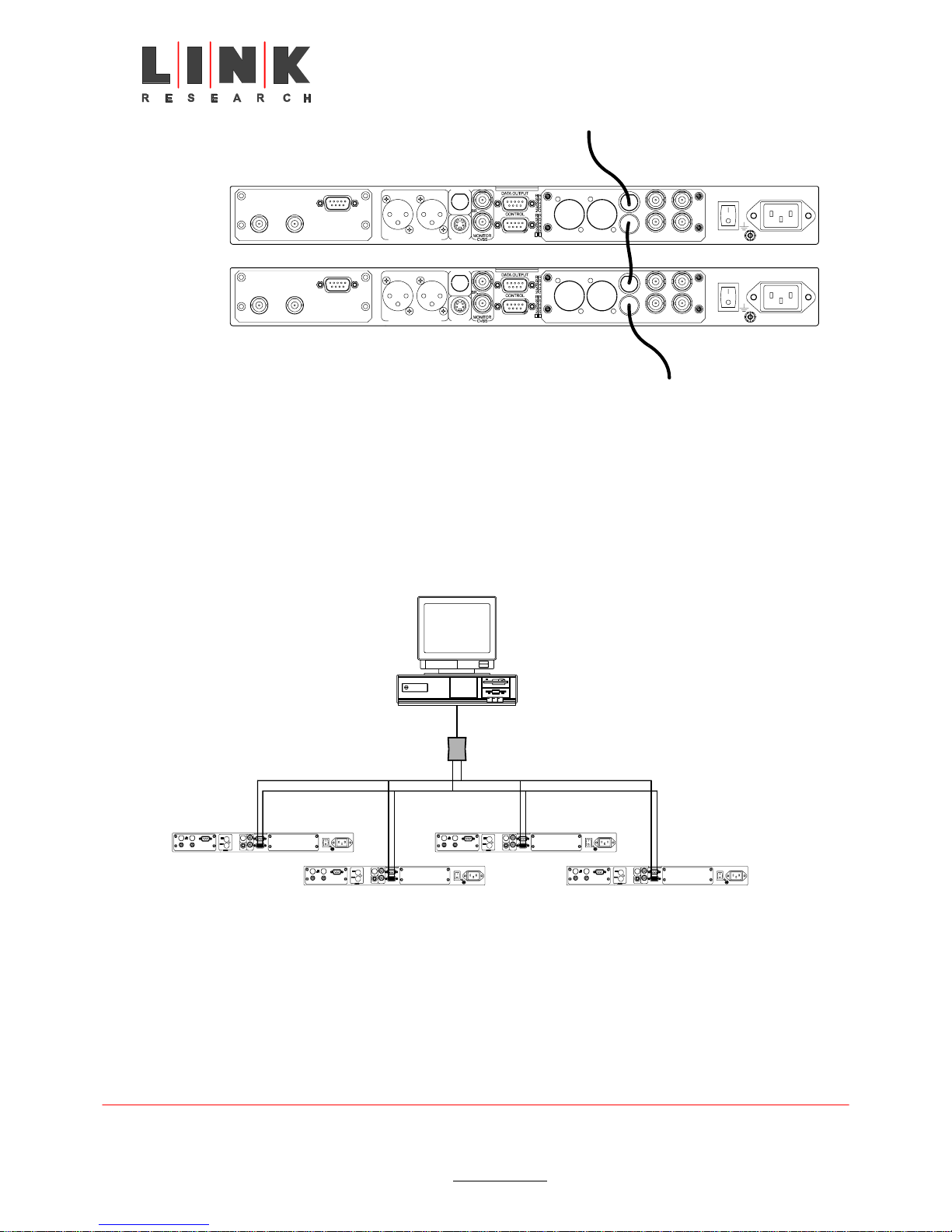
Multiple IRD devices can be managed from a single terminal control station using a Master
Slave configuration as shown in the figure below. As shown the Master-Slave configuration
uses a RS-232 to RS-485 converter. The converter is connected to a bus, which is in turn
connected to the IRD devices. The bus is comprised from transmit (Tx) and receive (Rx)
route. Each IRD device is identified on the bus by a unique address. All IRDs on the bus
will receive Tx and Rx messages, only the IRD with the matching address will respond to
the command of the Terminal.
Master-Slave RS-485 Control Cable Configuration
Tx Rx
IRD 1
L2101 &L2102 Integrated Receiver Decoder Instruction Manual – Issue 1 – September 2003 Page 34 of 126
Link Research Ltd. 23 Watford Metro Centre, Dwight Road, Watford, Hertfordshire, WD18 9XA, England.
Tel: +44 (0) 1923 200 900 Customer Support and Service +44 (0) 1923 200 909
Registered in London No. 2074604 Web: www.linkres.co.uk Fax: +44 (0) 1923 241 357
IRD 2
RS 232
RS 485
Rx
Tx
IRD 3
IRD 4

5.8 Initialization And Configuration
Prior to powering up the L2201 or L2202 Integrated Receiver Decoder, ensure that all
cabling is correctly connected as explained in Section 5.7. Ensure that the unit is
connected to the mains power supply and grounded according to instructions.
5.8.1 Powering Up
Upon power up, you will hear the internal fan commence operation and see the front panel
LCD display activated.
5.8.2 Initialization Sequence
Once the IRD is powered, the unit commences an initialization phase.
Initialization of the IRD includes loading of the embedded system parameters.
The IRD supports QPSK, QAM, ASI, RS-422, inputs. Depending on the selected input,
initialization sequences will differ. The initialization sequence may be monitored via the
Front Panel LCD. Status Messages are detailed in the IRD Operation Guide.
The initialization sequence is detailed in the table below. Prior to initialization, review the
IRD Operation Guide for instructions on how to use and navigate the system menus, and
for explanation of configuration parameters.
L2201 / L2202 Initialization Sequence
SEQ. # OPERATION DESCRIPTION
a. MPEG-DVB IRD –
Initializing Please Wait
b. PASSWORD If a password is defined for system access the enter
c. WARNING!
<Warning or Status Message>
d. CONFIG STATUS TEST RUN Go to System Menu.
e. TEST
ALL O.K.!
SERVICE: INTERNAL TEST
f. CONFIG STATUS TEST RUN Select the CONFIG option. To proceed with
On initialization, the LCD displays the initialization
message.
password prompt is displayed. If a password is not set
the system will proceed directly to point three.
WARNING! is displayed, with a message. This message
is normal on first time initialization. See IRD Operation
Guide “Status Messages” for list and definition of
messages.
If the word FAULT! appears, a hardware malfunction is
indicated. Contact Link Research for further instructions.
Select the TEST option.
For instructions on performing tests, refer to
Section on testing.
A successful test result is displayed on the LCD as ALL
O.K.!
Return the Test mode to NONE position to ensure that
the IRD returns to normal operation.
Return to the root menu.
configuration as required.
L2101 &L2102 Integrated Receiver Decoder Instruction Manual – Issue 1 – September 2003 Page 35 of 126
Tel: +44 (0) 1923 200 900 Customer Support and Service +44 (0) 1923 200 909
Link Research Ltd. 23 Watford Metro Centre, Dwight Road, Watford, Hertfordshire, WD18 9XA, England.
Registered in London No. 2074604 Web: www.linkres.co.uk Fax: +44 (0) 1923 241 357

DSNG Receiver Configuration Procedure
SEQ. # PARAMETER SET PROCEDURE INSTRUCTIONS
a.
b.
c.
d.
e.
f.
g.
h.
i.
j.
RECEIVER CONFIGURATION
Function Start.
The CONFIG sub menu is displayed.
Select the RECEIVER option and proceed to configure as
described below.
Frequency Range Parameter 1. Select Frequency Range option.
2. Set the frequency according to the BAND input.
LNB Power Supply Parameter 3. Select LNB Power Supply option.
4. Set the LNB Power Supply to: 14, 18 or OFF as
required
LNB 22 kHz Parameter 5. Select LNB 22 kHz option.
6. Using the controls, set the option to ON or OFF as
required
Input Signal Source Parameter 7. Select Input Signal Source option.
8. Set to A input.
Symbol Rate Parameter 9. Select Symbol Rate option.
10. Set the Symbol Rate as required.
Modulation Mode Parameter 11. Select Modulation Rate option.
12. Set to AUTOMATIC.
Nyquist Filter Roll-Off Parameter 13. Select Nyquist Filter Roll-Off option.
14. Set to AUTOMATIC.
Viterbi Rate Parameter 15. Select Viterbi Rate option.
16. Set to: 1/2, 2/3, 3/4, 4/5, 5/6, 6/7, 7/8, 8/9, or
AUTOMATIC as required.
Spectral Inversion Parameter 17. Select Spectral Inversion option.
18. Set the option to AUTOMATIC, NORMAL, or
INVERTED as required.
L2101 &L2102 Integrated Receiver Decoder Instruction Manual – Issue 1 – September 2003 Page 36 of 126
Tel: +44 (0) 1923 200 900 Customer Support and Service +44 (0) 1923 200 909
Link Research Ltd. 23 Watford Metro Centre, Dwight Road, Watford, Hertfordshire, WD18 9XA, England.
Registered in London No. 2074604 Web: www.linkres.co.uk Fax: +44 (0) 1923 241 357

QPSK Receiver Configuration Procedure
SEQ. # MENU DISPLAY MESSAGE PROCEDURE
a.
b.
c.
d.
e.
f.
g.
RECEIVER CONFIGURATION
Function Start.
The CONFIG sub menu is displayed.
Select the RECEIVER option and proceed to configure as
described below.
Frequency Range Parameter 1. Select Frequency Range option.
2. Set the frequency according to the BAND input.
LNB Power Supply Parameter 3. Select LNB Power Supply option.
4. Set the LNB Power Supply to: 14, 18 or OFF as
required
LNB 22 kHz Parameter 5. Select LNB 22 kHz option.
6. Using the controls, set the option to ON or OFF as
required
Symbol Rate Parameter 7. Select Symbol Rate option.
8. Set the Symbol Rate as required.
Viterbi Rate Parameter 9. Select Viterbi Rate option.
10. Set to: 1/2, 2/3, 3/4, 4/5, 5/6, 6/7, 7/8, 8/9, or
AUTOMATIC as required.
Spectral Inversion Parameter 11. Select Spectral Inversion option.
12. Set the option to AUTOMATIC, NORMAL, or
INVERTED as required.
QAM Receiver Configuration Procedure
SEQ. # MENU DISPLAY MESSAGE PROCEDURE
a.
RECEIVER CONFIGURATION
Function Start.
The CONFIG sub menu is displayed.
Select the RECEIVER option and proceed to configure as
described below.
b.
c.
VHF/UHF Frequency
Configuration Option
Symbol Rate Parameter 3. Select Symbol Rate option.
1. Select VHF/UHF Frequency option.
2. Set the required input frequency.
4. Set the symbol rate as required.
d.
Viterbi Rate Parameter 5. Select Viterbi Rate.option.
e.
Modulation Mode Parameter
6. Set the QAM mode to:
16 QAM, 32 QAM, 64 QAM, 128 QAM, or 256 QAM,
as required.
f.
Spectral Inversion Parameter 7. Select Spectral Inversion option.
8. Set the option to AUTOMATIC, NORMAL, or
INVERTED as required.
L2101 &L2102 Integrated Receiver Decoder Instruction Manual – Issue 1 – September 2003 Page 37 of 126
Tel: +44 (0) 1923 200 900 Customer Support and Service +44 (0) 1923 200 909
Link Research Ltd. 23 Watford Metro Centre, Dwight Road, Watford, Hertfordshire, WD18 9XA, England.
Registered in London No. 2074604 Web: www.linkres.co.uk Fax: +44 (0) 1923 241 357

5.8.3 Serviceability Check
After performing any installation, initialization, or configuration to the L2201 or L2202
Integrated Receiver Decoder, maintenance checks should be performed to ensure that the
unit is serviceable.
A Video Monitor must be connected to the L2201 in order to perform the check.
The table below provides a systematic instruction for performing a serviceability check.
Serviceability Check
# CHECK
1 Verify that the LCD Status Message reads ALL OK
2 Check for Video Picture on monitor
3 Toggle between Composite and S-VIDEO modes
4 Check Audio channels Left and Right
In the event that no video or audio output is received, perform a test on the decoder
audio/video stream.
To test the decoder audio/video stream:
From the Status Message, press the down arrow.
The System Menu is displayed.
Select the Test Menu.
The current operation shows NONE.
Select the NTSC Stream.
Press ENTER.
- Listen for the Test Sound (a brief musical sample) from the monitor speakers
- A Standard Test Pattern should be displayed on the TV Monitor.
When both Video and Audio tests are complete, return the TEST mode to the NONE state.
If you received any errors during the test, contact your vendor. If your IRD is not performing
as required, refer to the Operation Guide for further instructions.
L2101 &L2102 Integrated Receiver Decoder Instruction Manual – Issue 1 – September 2003 Page 38 of 126
Tel: +44 (0) 1923 200 900 Customer Support and Service +44 (0) 1923 200 909
Link Research Ltd. 23 Watford Metro Centre, Dwight Road, Watford, Hertfordshire, WD18 9XA, England.
Registered in London No. 2074604 Web: www.linkres.co.uk Fax: +44 (0) 1923 241 357

6 Operation
6.1 Introduction
This chapter describes the procedures required for the operation of the L2201 and L2202
Integrated Receiver Decoders.
Both L2201 and L2202 Integrated Receiver Decoders can be manually managed from the
IRD Front Control Panel, locally by a PC Terminal or remotely.
Manual management of the IRD is provided from the IRD Front Control Panel by the
keypad on the panel, or by using an optional Infrared Remote Control. The LCD on the
panel displays the menus and options of the IRD embedded software.
The Infrared Remote Control can be ordered through Link Research Ltd.
6.1.1 IRD Operation and Management
L2101 &L2102 Integrated Receiver Decoder Instruction Manual – Issue 1 – September 2003 Page 39 of 126
Tel: +44 (0) 1923 200 900 Customer Support and Service +44 (0) 1923 200 909
Link Research Ltd. 23 Watford Metro Centre, Dwight Road, Watford, Hertfordshire, WD18 9XA, England.
Registered in London No. 2074604 Web: www.linkres.co.uk Fax: +44 (0) 1923 241 357

6.1.2 Front Control Panel
The figure below shows the Front Control Panel of the IRD, its controls and features. The
following table explains the operation of the items found on the Front Control Panel.
NOTE
This panel is identical for the L2201 and for the L2202.
L2201 / L2202 Front Control Panel
LCD
®
I
CODICO SATELLITE R ECEIVER
R
D
2
6
Four Way Touch Pad ESC Touch Pad
Enter Touch Pad LED
E
n
t
e
E
s
c
.
Common Interface Card
Panel Cover
L2201 / L2202 Front Control Panel
CONTROL ITEM DESCRIPTION
LCD
The LCD is an alphanumeric display used to view the embedded
software, status messages, and parameter settings.
Four Way Touch Pad The Four Way Touch Pad enables navigation (UP, DOWN, LEFT
or RIGHT) in the embedded software menus by moving the cursor
position UP, DOWN, LEFT or RIGHT, respectively.
ENTER Touch Pad
Confirms/saves a selection or proceeds to next menu/item.
ESC Touch Pad
Exits from the current position or returns to the Status Message at
the top of the menus.
Status Indicator LED
The Status Indicator uses the following legend:
• Green Light / Constant: System Initializing and
Normal Operation.
• Green Light / Flashing: Service Warning.
• Orange Light / Constant: Bit Stream Warning.
• Red Light / Constant: Hardware Fault.
L2101 &L2102 Integrated Receiver Decoder Instruction Manual – Issue 1 – September 2003 Page 40 of 126
Link Research Ltd. 23 Watford Metro Centre, Dwight Road, Watford, Hertfordshire, WD18 9XA, England.
Tel: +44 (0) 1923 200 900 Customer Support and Service +44 (0) 1923 200 909
Registered in London No. 2074604 Web: www.linkres.co.uk Fax: +44 (0) 1923 241 357

6.1.3 Infrared Remote Control (Optional)
The figure below shows the optional infrared remote control available for the IRTD
operation.
IRD Infrared Remote Control
123 4 5 6 7
8910111213
The table below explains the control functions.
IRD Infrared Remote Control Items
# CONTROL FUNCTION
Motion
1
2
3
ESC
4
Play
Stop
Pause
Exits from the current message or returns to the Status Message when
working in the menus.
MENU
5
6
7
PR+/PRDecimal
Calls up Additional Commands.
Scrolls programs, increasing or decreasing by one.
Enables the first pressed numerical key to indicate the tens digit of the
program to be run.
0 to 9
8
Use to select preset program numbers.
In conjunction with the Decimal Key, the first numerical key pressed in a
sequence indicates the tens digit and the second numerical pressed key
indicates the units digit of the selected program.
In conjunction with the right touch pad, each key changes the value of the
digit indicated by the cursor.
Audio
9
10
11
SHIFT
Volume
Toggles audio mode ON/OFF (Mute/UnMute).
Not in use.
Increases or decreases program audio level.
12 FOUR WAY The four way touch buttons enable navigation (UP, DOWN, LEFT or RIGHT)
in the embedded software menus.
L2101 &L2102 Integrated Receiver Decoder Instruction Manual – Issue 1 – September 2003 Page 41 of 126
Tel: +44 (0) 1923 200 900 Customer Support and Service +44 (0) 1923 200 909
Link Research Ltd. 23 Watford Metro Centre, Dwight Road, Watford, Hertfordshire, WD18 9XA, England.
Registered in London No. 2074604 Web: www.linkres.co.uk Fax: +44 (0) 1923 241 357

IRD Infrared Remote Control Items
# CONTROL FUNCTION
ENTER
13
Confirms menu selection, saves a new parameter, or proceeds to the next
menu.
L2101 &L2102 Integrated Receiver Decoder Instruction Manual – Issue 1 – September 2003 Page 42 of 126
Tel: +44 (0) 1923 200 900 Customer Support and Service +44 (0) 1923 200 909
Link Research Ltd. 23 Watford Metro Centre, Dwight Road, Watford, Hertfordshire, WD18 9XA, England.
Registered in London No. 2074604 Web: www.linkres.co.uk Fax: +44 (0) 1923 241 357

6.2 Four Way Touch Pad.
The four way touch pad on the Front Control panel (see the figure below). Four way touch
buttons on the optional Infrared Remote Control (see the figure above) are used to
navigate in the embedded software menus:
• UP Touch Pad: Navigets Up in the menu tree.
• DOWN Touch Pad: Navigates Down in the menu tree.
• LEFT Touch Pad: Navigates Left in the menu branch.
• RIGHT Touch Pad: Navigate Right in the menu branch.
When the LCD displays the Start Up Menu, the pad is used as follows:
• UP and DOWN Touch Pads: No use.
LEFT Touch Pad: Displays the DVB Service option in the RUN/SERVICE menu (see
paragraph 6.15 ahead).
RIGHT Touch Pad: Displays the Network Channels option in the
CONFIGURATION/RECEIVER Menu (see paragraph 6.15ahead).
NOTE: Option available IRD with DSNG, QPSK or QAM front End interfaces.
L2101 &L2102 Integrated Receiver Decoder Instruction Manual – Issue 1 – September 2003 Page 43 of 126
Tel: +44 (0) 1923 200 900 Customer Support and Service +44 (0) 1923 200 909
Link Research Ltd. 23 Watford Metro Centre, Dwight Road, Watford, Hertfordshire, WD18 9XA, England.
Registered in London No. 2074604 Web: www.linkres.co.uk Fax: +44 (0) 1923 241 357

6.3 Front Panel Common Main Menu Options
The setup, control and monitoring of the IRD operation is locally provided using the
extended IRD Front Panel Menu. This menu is displayed on the Front Panel LCD and is
operated by the control pad on the IRD Front Panel or by the optional Remote Control (see
paragraph 6.1.1 above).
All configurations share a common initialization phase and, when successfully completed,
display the IRD Front Panel Main Menu structure, as shown in the figure below and
described in the following table. The following paragraphs provide detailed description of
each of the options in the Main Menu.
A dotted menu selection in the flowing diagrams indicates that the availability of this option
is dependent upon the system configuration. For example, Password control is available as
an option for the IRD. Once a session has been initiated via the Password, the password is
bypassed on repeated entry to the MAIN MENU.
Unless specifically marked, all functions are applicable for both the L2201 and the L2202.
IRD Front Panel Main Menu Structure.
Initialization
Password
Main Status
Display
CONFIG STATUS TEST RUN
RECEIVER DECODER SYSTEM SERVICE MODE ADVANCERECEIVER DECODER SYSTEM
L2101 &L2102 Integrated Receiver Decoder Instruction Manual – Issue 1 – September 2003 Page 44 of 126
Tel: +44 (0) 1923 200 900 Customer Support and Service +44 (0) 1923 200 909
Link Research Ltd. 23 Watford Metro Centre, Dwight Road, Watford, Hertfordshire, WD18 9XA, England.
Registered in London No. 2074604 Web: www.linkres.co.uk Fax: +44 (0) 1923 241 357

IRD Front Panel Main Menu Options.
MENU DESCRIPTION
Configuration
Menu
The Configuration Menu option enables access to the Receiver,
Decoder and System configuration parameters. These options are used to
define or modify the IRD configuration:
• The Receiver Configuration Menu provides functions to configure
the operation of the receiver, depending on the type of receiver
installed in the IRD; QPSK (DVB-S), DSNG (DVB-DSNG), QAM
(DVB-C)
• The Decoder Configuration Menu provides access to a further
sub-menu for Stream, CI, Video and Audio settings.
• The System Configuration Menu enables setup and control on the
IRD operation.
Status Menu The Status Menu option enables access to the Receiver, Decoder and
System status parameters. These options are used to view the IRDs
current configuration and status:
• Depending on the type of Receiver installed in the IRD, the Receiver
Status Menu provides functions to monitor the operation of the
receiver.
• The Decoder Status Men u provides access to a further sub-menu
for monitoring Stream, CI, Video and Audio operation.
• The System Status Menu enables viewing the IRD information.
Test Menu The Test Menu option enables access to special internal test procedures
on the Decoder section of the IRD.
Run Menu The Run Menu option enables access to high-level operation menus,
depending on the operation mode of the IRD – PID or Service Mode:
• When in Service Mode, the Run Menu provides sub-menus for
advanced control and operation functions, divided into Service, Mode
and Advance Sub-Menus.
• When in PID Mode, the Run Menu provides sub-menus for advanced
control and operation functions, divided into PID, Mode and Advance
Sub-Menus.
L2101 &L2102 Integrated Receiver Decoder Instruction Manual – Issue 1 – September 2003 Page 45 of 126
Tel: +44 (0) 1923 200 900 Customer Support and Service +44 (0) 1923 200 909
Link Research Ltd. 23 Watford Metro Centre, Dwight Road, Watford, Hertfordshire, WD18 9XA, England.
Registered in London No. 2074604 Web: www.linkres.co.uk Fax: +44 (0) 1923 241 357

6.4 Configuration Menu
The Configuration Menu enables the IRD operator to set-up the specific configuration
required of the IRD. The figure below shows the IRD Configuration Menu tree and the
options available to the user.
The IRD Front Panel display, controls and keypad are used to scroll through the menu,
view the options available and set the parameters of the configuration functions provided.
IRD Configuration Menu Tree Structure (DSNG IRD Configuration)
Initialization
Password
Main Status
Display
CONFIG STATUS TEST RUN
RECEIVER DECODER SYSTEM
Frequency Range
Ku/C Band L Band
LNB Local
Oscillator
LNB Power
Supply
Input Signal
Source
Transponder
Frequency
Symbol Rate
Modulatio n
Mode
Nyquist Filter
Roll-Off
Viterbi Rate
Spectral
Inversion
Freq. Drift
Compensation
Frequency
Scan
Network
Channel
LNB Local
Oscillator
LNB Power
Supply
LNB 22KHz
Input Signal
Source
L - Band
Frequency
Symbol Rate
Modulation
Mode
N requist Filter
Roll-Off
Viterbi Rate
Spectral
Inversion
Freq. Drift
compensation
Frequency
Scan
Network
Channels
STREAM CI VIDEO AUDIO
27 MHz
Synchronization
PTS-PCR
Synchronization
Loke Sync Mode
Service
Component
PID
Service ID
Source
When Current
Service N/A
Data1-HSD PID
Filtering
Data2-LSD PID
Filtering
C I Operation
Enable
CI [slot1]
PIN Code
CI [slot2]
PIN Code
Video Format
Video
Interpolation
IRD-2800 only
Video Lips
Sync Delay
Monitor Aspect
Ratio
Teletext
Insertion
Subtitle Prefer
Language
Teletext
Subtiling Page
VITS Insertion
VITC Insertion
SMC Insertion
VPS Insertion
CC Insertion
Audio Decoder
Operation
AC3 Sampling
Frequency
Audio1 Prefered
Language
Audio2 Prefered
Language
Audio3 Prefered
Language
Audio4 Prefered
Language
Display
Contrast
Software
Reset
Product Type
Control Port
232 Syntax
Control Port
Baud Rate
Control Port
Address
Data1-HSD
Output Format
Data2-LSD
Output Format
Data1-HSD
Output Rate
Data2-LSD
Output Rate
Default Data
Port
DSNG-CA
Encryption Key
Session Word
L2101 &L2102 Integrated Receiver Decoder Instruction Manual – Issue 1 – September 2003 Page 46 of 126
Link Research Ltd. 23 Watford Metro Centre, Dwight Road, Watford, Hertfordshire, WD18 9XA, England.
Tel: +44 (0) 1923 200 900 Customer Support and Service +44 (0) 1923 200 909
Registered in London No. 2074604 Web: www.linkres.co.uk Fax: +44 (0) 1923 241 357
Injected ID

6.5 Configuration / Receiver Menu
The IRD is provided in a wide range of input receivers: QPSK (DVB-S), DSNG
(DVB-DSNG), QAM (DVB-C) receiver options. The Configuration / Receiver Menu is input
sensitive (i.e., varies automatically according to the IRD Input option installed), and
provides a group of functions to configure the receiver section of the IRD.
The IRD Front Panel display, controls and keypad are used to scroll through the menu,
view the options available and set the parameters of the configuration functions provided.
The figure below shows the configuration functions available for the receiver option
installed in the L2201 / L2202 (DSNG, QPSK, QAM).
The ; icon legend is used to show menu option availability for the different input receiver:
L2101 &L2102 Integrated Receiver Decoder Instruction Manual – Issue 1 – September 2003 Page 47 of 126
Link Research Ltd. 23 Watford Metro Centre, Dwight Road, Watford, Hertfordshire, WD18 9XA, England.
Tel: +44 (0) 1923 200 900 Customer Support and Service +44 (0) 1923 200 909
Registered in London No. 2074604 Web: www.linkres.co.uk Fax: +44 (0) 1923 241 357

CONFIG
RECEIVER
DSNG
Front End
Frequency Range
Ku/C Band L Band
LNB Local
Oscillator
LNB Power
Supply
Input Signal
Source
Transponder
Frequency
Symbol Rate
Modulation
Mode
Nyquist Filter
Roll-Off
Viterbi Rate
Spectral
Inversion
Freq. Drift
Compensation
Frequency
Scan
Network
Channel
LNB Local
Oscillator
LNB Power
Supply
LNB 22KHz
Input Signal
Source
L-Band
Frequency
Symbol Rate
Modulation
Mode
NrequistFilter
Roll-Off
Viterbi Rate
Spectral
Inversion
Freq. Drift
compensation
Frequency
Scan
Network
Channels
QPSK
Front End
Frequency Range
Ku/C Band L Band
LNB Local
Oscillator
LNB Power
Supply
Input Signal
Source
Transponder
Frequency
Symbol Rate
Viterbi Rate
Spectral
Inversion
Freq. Drift
Compensation
Frequency
Scan
Network
Channel
LNB Local
Oscillator
LNB Power
Supply
LNB 22KHz
Input Signal
Source
L - Band
Frequency
Symbol Rate
Viterbi Rate
Spectral
Inversion
Freq. Drift
compensation
Frequency
Scan
Network
Channels
QAM
Front End
Input Signal
Source
VHF
Frequency
Symbol Rate
Spectral
Inversion
QAM Mode
Freq. Drift
Compensation
Frequency
Scan
Network
Channels
L2101 &L2102 Integrated Receiver Decoder Instruction Manual – Issue 1 – September 2003 Page 48 of 126
Link Research Ltd. 23 Watford Metro Centre, Dwight Road, Watford, Hertfordshire, WD18 9XA, England.
Tel: +44 (0) 1923 200 900 Customer Support and Service +44 (0) 1923 200 909
Registered in London No. 2074604 Web: www.linkres.co.uk Fax: +44 (0) 1923 241 357

QAM
DSNG Receiver Configuration Menu Tree Structure
OPTION DESCRIPTION
DSNG
QPSK
; ;
; ;
; ;
Frequency
Range
LNB Local
Oscillator
LNB Power
Supply
Frequency Range Selector
This parameter supports various frequency ranges for a satellite
band range receiver. Two options are provided:
L-Band: Receiving in the L-Band frequency range.
Satellite (Ku/C) Band: Receiving in the Ku/C-Band frequency range.
LNB Oscillator Setup
The LNB Local Oscillator (LO) provided with the receiving antenna
unit, down converts the carrier frequency of the incoming signal to a
range acceptable to the receiver. This is achieved by down
converting the frequency of the incoming signal.
However, for display accuracy, the selected LNB Local Oscillator
frequency must be in accordance with the frequency of the receiving
antenna installed in the system (disregarding the frequency provided
at the IRD input).
The LNB Local Oscillator parameter has following select options:
PARAMETER BAND PARAMETER BAND
DiSeQC * (9750-10600) 10600 (Ku Band)
Wide Band (9750-10750) 10700 (Ku Band)
Universal (9750-10600) 10750 (Ku Band)
05150 (C Band) 10950 (Ku Band)
05950 (C Band) 11250 (Ku Band)
09750 (Ku Band) 11300 (Ku Band)
10000 (Ku Band) 11700 (Ku Band)
10250 (Ku Band) 12500 (Ku Band)
* DiSeQC band (9750-10600) is available only for the DSNG
Receiver option.
LNB Power Supply Setup
The polarization of the receiving antenna is determined according to
the requirements in the broadcast program parameters. The IRD
controls the polarization of the receiving antenna by means of the
voltage provided to the LNB Power Supply.
Available options:
OFF: Power Supply off.
14 (Vertical): 14 V Power Supply / Vertical Polarization.
18 (Horizontal): 18 V Power Supply / Horizontal Polarization.
L2101 &L2102 Integrated Receiver Decoder Instruction Manual – Issue 1 – September 2003 Page 49 of 126
Tel: +44 (0) 1923 200 900 Customer Support and Service +44 (0) 1923 200 909
Link Research Ltd. 23 Watford Metro Centre, Dwight Road, Watford, Hertfordshire, WD18 9XA, England.
Registered in London No. 2074604 Web: www.linkres.co.uk Fax: +44 (0) 1923 241 357

DSNG
QAM
QPSK
OPTION DESCRIPTION
; ;
;
;* ;*
LNB 22KHz
LNB 22 KHz Selector
Turns ON and OFF the 22 KHz LNB. This action determines the
band selected (ON = High Band, OFF = Low Band). In addition, the
selection of the LNB Power Supply determines the polarization of the
antenna. The following table shows the correlation between the LNB
parameters:
LNB POWER SUPPLY
LNB POLARIZATION
14V / Vertical Polarization
18V / Horizontal Polarization
LNB 22 KHZ LNB BAND
OFF Low Band
ON High Band
OFF Low Band
ON High Band
NOTE
In the Ku/C band mode, the LNB 22KHz converter setting is
performed automatically and the LNB 22 KHz Receiver
Configuration function is not displayed in the Receiver
Configuration Menu.
Input Signal
Source
Input Select
Selects the input source for the IRD Receiver input.
Available options:
In-A: Selects Input A
In-B: Selects Input B
; ;
; ;
L2101 &L2102 Integrated Receiver Decoder Instruction Manual – Issue 1 – September 2003 Page 50 of 126
Link Research Ltd. 23 Watford Metro Centre, Dwight Road, Watford, Hertfordshire, WD18 9XA, England.
Tel: +44 (0) 1923 200 900 Customer Support and Service +44 (0) 1923 200 909
L-Band
Frequency
Transponder
Frequency
Registered in London No. 2074604 Web: www.linkres.co.uk Fax: +44 (0) 1923 241 357
NOTE (;*)
The In-B connector is standard in the DSNG application.
For all other receivers (QPSK) the IN-B connector is
connected as loop-through of In-A input.
As an option, an additional, independent In-B input can be
added to these receivers. When this option is implemented for
any one of the receivers, the Input Select function is available
in the Receiver Configuration Menu to select between In-A
and In-B.
L-Band Receiver Frequency Selection
Input of the calculated L-Band Frequency for the DSNG IRD and
QPSK IRD Receivers in the L-Band, as described in Appendix A.
Ku/C-Band Frequency Selection
Input of the Satellite Transponder (Ku or C Band) frequency for the
DSNG IRD and QPSK IRD Receivers in the Ku/C Band.
See Appendix A for an example on calculating the input frequency.

DSNG
QAM
QPSK
;
; ; ;
;
;
;
OPTION DESCRIPTION
VHF/UHF
Frequency
VHF/UHF-Band Frequency Selection
Displays the expected carrier frequency of the received input signal
at the QAM (DVB-C) application.
Symbol Rate
Symbol Rate Setup
The Symbol Rate for a group of station programs is configured
according to the broadcast program parameters and the specific
ranges available in your IRD.
The available Symbol Rate range is:
QPSK and DSNG 1-45 configuration: 1 to 45 Mbaud/sec.
QAM configuration: 1 to 7.2 Mbaud/sec.
If the Bit rate information is provided but no Symbol Rate information
is given, the Symbol Rate may be calculated by the equations
provided in Appendix B.
NOTE
It is important to input the Symbol Rate accurately, including all the
decimal places that are given.
QAM Mode
Modulation
Mode
Nyquist Filter
Roll-Off
QAM Mode Select
Selects the QAM Mode of operation for the QAM IRD.
Available options:
16_QAM, 32_QAM, 64_QAM, 128_QAM, 256_QAM.
Modulation Mode Select
Selects the modulation mode for the DSNG IRD. Available options:
MOD – QPSK: Quadrature Shift Keying Modulation.
MOD – 8PSK: Eight Phase Shift Keying Modulation.
MOD – 16 QAM: 16 Quadrature Amplitude Modulation.
Automatic: Automatic Selection of modulation.
Nyquist Filter Type Selection
Selects the roll-off parameter for the Nyquist filter.
Available options:
35%: 35% roll-off parameter.
25%: 25% roll-off parameter.
Automatic: Automatic selection of the roll-off parameter (25% or
35%).
L2101 &L2102 Integrated Receiver Decoder Instruction Manual – Issue 1 – September 2003 Page 51 of 126
Tel: +44 (0) 1923 200 900 Customer Support and Service +44 (0) 1923 200 909
Link Research Ltd. 23 Watford Metro Centre, Dwight Road, Watford, Hertfordshire, WD18 9XA, England.
Registered in London No. 2074604 Web: www.linkres.co.uk Fax: +44 (0) 1923 241 357

DSNG
QAM
QPSK
OPTION DESCRIPTION
; ;
; ; ;
; ; ;
; ; ;
Viterbi Rate
Spectral
Inversion
Freq Drift
Compensation
Frequency Scan
Viterbi Rate Select
This parameter is configured according to the information provided
from the broadcast head end.
The available values are:
Auto, 1/2, 2/3, 3/4, 4/5, 5/6, 6/7, 7/8, 8/9.
NOTE
If the specific Viterbi rate is not provided, selecting the AUTO option
enables the IRD to automatically detect the Viterbi rate.
Spectral Inversion Select
Selects the operation mode of the spectral inversion options.
Available options:
Automatic: IRD automatic selection between Normal and Inverted
spectral inversion.
Normal: Normal spectral inversion.
Inverted: Inverted spectral inversion.
Frequency Drift Compensation Activation
ENABLE/DISABLE the frequency drift compensation function
(caused by LNB drift and enviromental changes).
Frequency Scan Select
This utility provides two frequency scan options, used to find DVB
transmission signals:
Scan Frequency between +/- 6 MHz:
Allows scanning a frequency range of ± 6 MHz from the current
tuning frequency.
Entire Current Band:
Scan the entire band to find the DVB Network frequencies. The
detected frequency (and it’s parameters) are stored in volatile
memory. Powering down the IRD will erase them.
; ; ;
L2101 &L2102 Integrated Receiver Decoder Instruction Manual – Issue 1 – September 2003 Page 52 of 126
Link Research Ltd. 23 Watford Metro Centre, Dwight Road, Watford, Hertfordshire, WD18 9XA, England.
Tel: +44 (0) 1923 200 900 Customer Support and Service +44 (0) 1923 200 909
Network
Channels
Registered in London No. 2074604 Web: www.linkres.co.uk Fax: +44 (0) 1923 241 357
NOTE
The user must save the settings manually in the non-volatile
memory.
Network Channels Select
In systems where several network channels has been detected, this
option allows the user to select one network channel from an
incoming satellite signal.
NOTE
This option can be accessed directly from the Start Up Menu by
pressing the RIGHT Touch Pad on the on the Front Panel.

6.5.1 Configuration / Decoder Menu
The Decoder Configuration menu provides the IRD user the capability to setup and
configure the decoder in the IRD. Figure 0-1 shows the menu tree of configuration
functions available in the Decoder Configuration Menu (password is required only if it was
enabled previously).
The IRD Front Panel display, controls and keypad are used to scroll through the menu,
view the options available and set the parameters of the configuration functions provided.
The Decoder Configuration functions are grouped into four groups and are described in the
following sub-paragraphs:
• Decoder/Stream functions configuration sub-menu, refer to paragraph 0.
• Decoder/Common Interface (CI) functions configuration sub-menu, refer to paragraph 0.
• Decoder/Video functions configuration sub-menu, refer to paragraph 0.
• Decoder/Audio functions configuration sub-menu, refer to paragraph 0.
L2101 &L2102 Integrated Receiver Decoder Instruction Manual – Issue 1 – September 2003 Page 53 of 126
Tel: +44 (0) 1923 200 900 Customer Support and Service +44 (0) 1923 200 909
Link Research Ltd. 23 Watford Metro Centre, Dwight Road, Watford, Hertfordshire, WD18 9XA, England.
Registered in London No. 2074604 Web: www.linkres.co.uk Fax: +44 (0) 1923 241 357

Figure 0-1: Decoder Configuration Menu Tree Structure
Initialization
Password
Main Status
Display
CONFIG STATUS TEST RUN
RECE IVER DECOD ER SYSTEM
STREAM CI VIDEO AUDIO
27 MHz
Synchronization
PTS-PCR
Synchronization
Loke Sync Mode
Service
Component
PID
Service ID
Source
When Current
Service N/A
Data1-HSD PID
Filtering
Data2-LSD PID
Filtering
C I Operation
Enable
CI [slot1]
PIN Code
CI [slot2]
PIN Code
Video Format
Video
Interpolation
IRD-2800 only
Video Lips
Sync Delay
Monitor Asp ect
Ratio
Teletext
Insertion
Subtitle Prefer
Language
Teletext
Subtiling Page
VITS Insertion
VITC Insertion
SMC Insertion
VPS Insertion
Audio Decoder
Operation
AC3 Sampling
Frequency
Audio1 Prefered
Language
Audio2 Prefered
Language
Audio3 Prefered
Language
Audio4 Prefered
Language
L2101 &L2102 Integrated Receiver Decoder Instruction Manual – Issue 1 – September 2003 Page 54 of 126
Link Research Ltd. 23 Watford Metro Centre, Dwight Road, Watford, Hertfordshire, WD18 9XA, England.
Tel: +44 (0) 1923 200 900 Customer Support and Service +44 (0) 1923 200 909
Registered in London No. 2074604 Web: www.linkres.co.uk Fax: +44 (0) 1923 241 357
CC Insertion

Decoder / Stream Configuration Sub-Menu
The Decoder / Stream Configuration Sub-Menu provides an extended menu of setup and
selection options to configure the decoder’s streams.
Figure 0-2 shows the menu tree of configuration functions available in the Decoder /
Stream Configuration Sub-Menu. Error! Reference source not found. describes the
configuration functions provided to the IRD operator in the sub-menu.
Figure 0-2: Decoder / Stream Configuration Sub-Menu Tree Structure
CONFIG
Decoder
STREAM CI VIDEO AUDIO
27 MHz
Synchronization
PTS-PCR
Synchronization
Lock Sinc Mode
Service
Component
PID
Service ID
Source
When Current
Service N/A
Data1-HSD PID
Filtering
Data2-LSD PID
Filtering
L2101 &L2102 Integrated Receiver Decoder Instruction Manual – Issue 1 – September 2003 Page 55 of 126
Link Research Ltd. 23 Watford Metro Centre, Dwight Road, Watford, Hertfordshire, WD18 9XA, England.
Tel: +44 (0) 1923 200 900 Customer Support and Service +44 (0) 1923 200 909
Registered in London No. 2074604 Web: www.linkres.co.uk Fax: +44 (0) 1923 241 357

Decoder / Stream Configuration Menu Options
OPTION DESCRIPTION
27 MHz Synchronization
PTS-PCR
Synchronization
Lips Sync Mode
Service Component PID
Service ID Source
Decoder Synchronization Source
The IRD is synchronized by a 27MHz clock, generated by a Voltage
Controlled Oscillator (VCXO).
This function enables the user to select a synchronization source for the
VCXO.Options available:
Internal: The VCXO is factory calibrated to a fixed 27 MHz clock.
External Video Sync: The VCXO is synchronized to an external video
signal.
External Stream PCR: The VCXO is synchronized by the stream Program
Clock Recovery (PCR) signal, received with the stream data.
Lips Synchronization.
ENABLE/DISABLE the PTS – PCR (picture/video and sound/audio), “lips”
synchronization, using the Presentation Time Stamp (PTS) and PCR
signals from the stream data.
Lips Synchronization Mode.
Selects the operating mode for the “Lips” PTS-PCR Synchronization
function. (Active when PTS-PCR synchronization is ENABLED).
Options available:
Locked: Picture/video and sound/audio are locked (±2mSec).
Standard: (Standard Synch of video and audio data (±40mSec).
Option available for L2202 only.
Service Information Set-Up Mode
Selects the set-up mode for the service components information:
Manually by User:
Switches the IRD to PID mode. Service Information must be manually
provided when in PID Mode.
DVB Service Content:
Switches the IRD to Service Mode. When in Service Mode, the IRD
extracts service information from the PSI-SI tables contained in the stream.
Service ID Source Selection
Selects the source for the identification data on the services received.
Options available:
Stream PSI-SI Tables:
External information provided by the stream PSI/SI tables.
Pre-programmed Memory:
Pre-saved information in the IRD programmed non-volatile memory.
L2101 &L2102 Integrated Receiver Decoder Instruction Manual – Issue 1 – September 2003 Page 56 of 126
Tel: +44 (0) 1923 200 900 Customer Support and Service +44 (0) 1923 200 909
Link Research Ltd. 23 Watford Metro Centre, Dwight Road, Watford, Hertfordshire, WD18 9XA, England.
Registered in London No. 2074604 Web: www.linkres.co.uk Fax: +44 (0) 1923 241 357

Decoder / Stream Configuration Menu Options
OPTION DESCRIPTION
When Curren t Service
Not Available
Current Service Not Available Response
Defines the reaction of the IRD when the current service is not available:
Automatic call 1st Active
The IRD will auto select the first active service.
Wait for User command
The IRD will wait in the current service until the user will change his
request.
Data1-HSD PID Filtering Data1High Speed Data Filtering Options
Selects the filtering applied to the Data1 (HSD PID) information:
P.E.S Payload:
Strips the header of the Packetised Elementry Stream (PES).
Entire Transport Packet:
Enables the entire transport stream packet (188 bytes).
Transport Payload:
Strips the transport stream header (first 4 bytes on of the 188 bytes).
Data2-LSD PID Filtering
Data2 Low Speed Data Filtering Options
Selects the filtering applied to the Data1 (LSH PID) information:
P.E.S Payload:
Strips the header of the Packetised Elementry Stream (PES).
Entire Transport Packet:
Enables the entire transport stream packet (188 bytes).
Transport Payload:
Strips the transport stream header (first 4 bytes on of the 188 bytes).
DVB streaming:
Streams the Data2/LSD stream according to the DVB specifications
(EN 301 192, paragraph 5 and 6).
L2101 &L2102 Integrated Receiver Decoder Instruction Manual – Issue 1 – September 2003 Page 57 of 126
Tel: +44 (0) 1923 200 900 Customer Support and Service +44 (0) 1923 200 909
Link Research Ltd. 23 Watford Metro Centre, Dwight Road, Watford, Hertfordshire, WD18 9XA, England.
Registered in London No. 2074604 Web: www.linkres.co.uk Fax: +44 (0) 1923 241 357

6.5 Decoder/CI Configuration Sub-Menu
The Decoder/Common Interface (CI) Configuration Sub-Menu provides setup and
configuration options for the CI function.
The following table shows the menu tree for the Decoder / CI Configuration Sub-Menu.
Describes the Options in the Sub Menu.
OPTION DESCRIPTION
CI Operation Enable
CI [slot 1] PIN Code
CI [slot 2] PIN Code
Decoder / CI Configuration Sub-Menu Tree Structure
STREAM CI VIDEO AUDIO
CI Operation Control.
ENABLE / DISABLE the common Interface Function.
PIN Code for CI / Slot 1
Enables the user to enter the password (PID /Code) for the smart card
installed in CI / slot 1.
PIN Code for CI / Slot 2
Enables the user to enter the password (PID /Code) for the smart card
installed in CI / slot 2.
CONFIG
DECODER
C I Operation
Enable
CI [slot1]
PIN Code
L2101 &L2102 Integrated Receiver Decoder Instruction Manual – Issue 1 – September 2003 Page 58 of 126
Link Research Ltd. 23 Watford Metro Centre, Dwight Road, Watford, Hertfordshire, WD18 9XA, England.
Tel: +44 (0) 1923 200 900 Customer Support and Service +44 (0) 1923 200 909
Registered in London No. 2074604 Web: www.linkres.co.uk Fax: +44 (0) 1923 241 357
CI [slot2]
PIN Code

6.6 Decoder / Video Configuration Sub-Menu
The Decoder / Video Configuration Sub-Menu provides an extended menu of setup and
selection options to configure the decoder’s video signal generated from the input data.
The figure below shows the menu tree of configuration functions available in the Decoder /
Video Configuration Sub-Menu. The table below describes the configuration functions
provided to the IRD operator in the sub-menu.
Decoder / Video Configuration Sub-Menu Tree Structure
CONFIG
DECODER
STREAM CI VIDEO AUDIO
Video Format
Video
Interpolation
IRD-2800 only
Video Lips
Sync Delay
Monitor Aspect
Ratio
Teletext
Insertion
Subtitle Prefer
Language
Teletext
Subtiling Page
VITS Insertion
VITC Insertion
SMC Insertion
VPS Insertion
CC Insertion
L2101 &L2102 Integrated Receiver Decoder Instruction Manual – Issue 1 – September 2003 Page 59 of 126
Link Research Ltd. 23 Watford Metro Centre, Dwight Road, Watford, Hertfordshire, WD18 9XA, England.
Tel: +44 (0) 1923 200 900 Customer Support and Service +44 (0) 1923 200 909
Registered in London No. 2074604 Web: www.linkres.co.uk Fax: +44 (0) 1923 241 357

Decoder / Video Configuration Sub-Menu Options
OPTION DESCRIPTION
Video Format
Video Interpolation
Video Lips Sync Delay
Monitor Aspect Ratio
Teletext Insertion
Subtitle Prefer Language
Video Format Selection
Selects the output format of the video signal. Options available are:
PAL N, PAL B/G, PAL M, NTSC, PAL D/I, SECAM
Video Interpolation Selection
Selects the interpolation format of the output video signal.
Options available are:
Pan Scan: Activates the expand resolution function for the received
picture (full resolution out of half or quarter)
Pass Through: No expansion, picture resolution is provided as received.
Letter Box: Picture is in “letter box” format.
Lips Synchronization Delay Setup
Sets the delay between video and audio data when the “lips” PTS-PCR
Synchronization function is “locked” (see paragraph 3.4.2.1).
Delay range available: from –20 to +20 mSec (negative for delay of audio).
Option available for L2202 ONLY.
Aspect Ratio Select
Selects the aspect ration for the displayed picture:
16:9, or 4:3, or 14:9: Selects the monitor type connected to the IRD.
The IRD will insert the Wide Screen Signaling (WSS, line 23) signal,
accordingly.
W.S.S Disabled: The IRD will not insert (disable) the WSS signal.
Transparent to Encoder: The IRD will set the WSS in accordance with
the video stream ratio detected.
Teletext Insertion Control
Enable/Disable the insertion of Teletext information in the VBI.
Preferred Language for Subtitles.
Selects the preferred language for the displayed sub-titles.
Option available:
ALL (default): No preferred language is selected. The subtitle language is
set according to the Service PID.
1. English.
2. Arabic.
3. Bulgarian.
4. Chinese.
5. Dutch.
6. Danish.
7. German.
8. Greek Modern.
9. Finnish.
10. French.
11. Hebrew.
12. Hungarian.
13. Irish.
14. Italian.
15. Japanese.
16. Norwegian..
17. Turkish
18. Persian.
19. Polish.
20. Portuguese.
21. Romanian.
22. Russian.
23. Spanish.
24. Swedish.
L2101 &L2102 Integrated Receiver Decoder Instruction Manual – Issue 1 – September 2003 Page 60 of 126
Tel: +44 (0) 1923 200 900 Customer Support and Service +44 (0) 1923 200 909
Link Research Ltd. 23 Watford Metro Centre, Dwight Road, Watford, Hertfordshire, WD18 9XA, England.
Registered in London No. 2074604 Web: www.linkres.co.uk Fax: +44 (0) 1923 241 357

Decoder / Video Configuration Sub-Menu Options
OPTION DESCRIPTION
Teletext Subtitling Page
VITS Insertion
VITC Insertion
SMC Insertion
VPS Insertion
CC Insertion
Teletext Subtitling Select
Selects a page number for the EBU Teletext Subtitling.
Options available are: 100, through 899.
NOTES:
The Teletext Subtitling function is available ONLY when the PID mode is
activated.
Selection of the EBU Teletext Subtitling page from the PSI/SI tables can
also be done using the RUN/SERVICE Sub-Menu (see paragraph 6.15,
“TSubtitle SubService” option).
VITS Insertion Selection
Selects the Video Internal Test Signals (VITS) Insertion type:
Disable
VBI Lines 19,20
VBI Lines 17,18
VBI Line 17 (NTSC)
VITC Insertion Selection
Selects the Video Internal Time Code (VITC) Insertion type:
Disable
VBI Lines 12,14 (Extrn)
VBI Lines 14,16 (Extrn)
VBI Lines 16,18 (Extrn)
VBI Line 14 (Extrn)
VBI Line 19 (Extrn)
VBI Lines 12, 14 (Intrn)
VBI Lines 14 (I ntrn)
NOTE
Extrn: The time code is taken from the stream GOP Header.
Intrn: The time code is locked to the internal IRD clock.
SMC Insertion Control
Enable/Disable the Sound Mode Control (SMC) insertion.
VPS Insertion Control
Enable/Disable the Video Programming Signal (VPS) insertion.
CC Insertion Control
Controls the Closed Caption (CC) insertion.
Option available:
Disable: Disables CC insertion.
Enable (Decode LSB => MSB): Enables CC insertion LSB first.
Enable (Decode MSB => LSB): Enables CC insertion MSB first.
L2101 &L2102 Integrated Receiver Decoder Instruction Manual – Issue 1 – September 2003 Page 61 of 126
Tel: +44 (0) 1923 200 900 Customer Support and Service +44 (0) 1923 200 909
Link Research Ltd. 23 Watford Metro Centre, Dwight Road, Watford, Hertfordshire, WD18 9XA, England.
Registered in London No. 2074604 Web: www.linkres.co.uk Fax: +44 (0) 1923 241 357

6.7 Decoder / Audio Configuration Sub-Menu
The Decoder / Audio Configuration Sub-Menu provides an extended menu of setup and
selection options to configure the decoder’s audio signals generated from the input data.
The figure below shows the menu tree of configuration functions available in the Decoder /
Audio Configuration Sub-Menu. The table below describes the configuration functions
provided to the IRD operator in the sub-menu.
Decoder / Audio Configuration Sub-Menu Tree Structure
CONFIG
DECODER
STREAM CI VIDEO AUDIO
Audio Decoder
Operation
AC3 Sampling
Frequency
Audio1 Prefered
Language
Audio2 Prefered
Language
Audio3 Prefered
Language
L2101 &L2102 Integrated Receiver Decoder Instruction Manual – Issue 1 – September 2003 Page 62 of 126
Link Research Ltd. 23 Watford Metro Centre, Dwight Road, Watford, Hertfordshire, WD18 9XA, England.
Tel: +44 (0) 1923 200 900 Customer Support and Service +44 (0) 1923 200 909
Registered in London No. 2074604 Web: www.linkres.co.uk Fax: +44 (0) 1923 241 357

Decoder / Video Configuration Sub-Menu Options
OPTION DESCRIPTION
Audio Decoder
Operation
AC3 Sampling
Frequency
Audio1 Prefered
Language
Audio2 Prefered
Language
Audio3 Prefered
Language
Audio Decoder Operation
Selects the digital audio operation mode.
Available options:
MPEG: Musicam Decoding
AC3 Passthru (IEC 1937): Digital output only.
Linear PCM Audio: Available only in the L2202.
AC3 Sampling Frequency Select
Selects the sampling frequency for the AC3 pass through function in the
digital audio function provided by the IRD.
Available options are: 48 KHz, 44.1 KHz, 32 KHz
Preferred Language for Subtitles.
Selects the preferred language for the audio1 (or audio2, audio3
respectively).
Option available:
ALL (default): No preferred language is selected. The audio language is
set according to the Service PID.
1. English.
2. Arabic.
3. Bulgarian.
4. Chinese.
5. Dutch.
6. Danish.
7. German.
8. Greek Modern.
9. Finnish.
10. French.
11. Hebrew.
12. Hungarian.
13. Irish.
14. Italian.
15. Japanese.
16. Norwegian..
17. Turkish
18. Persian.
19. Polish.
20. Portuguese.
21. Romanian.
22. Russian.
23. Spanish.
24. Swedish.
L2101 &L2102 Integrated Receiver Decoder Instruction Manual – Issue 1 – September 2003 Page 63 of 126
Tel: +44 (0) 1923 200 900 Customer Support and Service +44 (0) 1923 200 909
Link Research Ltd. 23 Watford Metro Centre, Dwight Road, Watford, Hertfordshire, WD18 9XA, England.
Registered in London No. 2074604 Web: www.linkres.co.uk Fax: +44 (0) 1923 241 357

6.8 Configuration/System Menu
The System Configuration Menu provides the IRD user the capability to set-up and
configure the IRD operation. The figure below shows the menu tree of system level
configuration functions available in the System Configuration Menu (password is required
only if it was enabled previously). The table below describes each configuration function
and the options available to the IRD user.
The IRD Front Panel display, controls and keypad are used to scroll through the menu,
view the options available and set the parameters of the configuration functions provided.
System Configuration Menu Tree Structure
CONFIG STATUS TEST RUN
RECEIVER DECODER SYSTEM
Display
Contrast
Software
Reset
Product Type
Control Port
232 Syntax
Control Port
Baud Rate
Control Port
Address
Data1-HSD
Output Format
Data2-LSD
Output Format
Data1-HSD
Output Rate
Data2-LSD
Output Rate
Default Data
Port
DSNG-CA
Encryption Key
Session Word
Injected ID
L2101 &L2102 Integrated Receiver Decoder Instruction Manual – Issue 1 – September 2003 Page 64 of 126
Link Research Ltd. 23 Watford Metro Centre, Dwight Road, Watford, Hertfordshire, WD18 9XA, England.
Tel: +44 (0) 1923 200 900 Customer Support and Service +44 (0) 1923 200 909
Registered in London No. 2074604 Web: www.linkres.co.uk Fax: +44 (0) 1923 241 357

System Configuration Menu Options
OPTION DESCRIPTION
Display Contrast
Software Reset
Product Type
Control Port-232 Syntax
Display Contrast Level Set-Up
Controls the display contrast of the LCD display on the front panel of the
IRD.
Contrast level is set as follows:
The [up] touch-pad increases the contrast level, and
The [down] touch-pad to decreases the contrast.
IRD Reset
This function resets the IRD.
The following choices are available:
Warm Boot (Reset): for a minimum reset..
Cold Boot (Power-Up): for a complete power up of the IRD device.
Product Type Configuration
This function defines the basic product configuration’ IRD or Decoder.
NOTE
The IRD input module is factory installed and cannot be changed by
hardware replacement.
The Decoder software can be updated when required.
The available options are:
IRD (DSNG):
Displays the factory predefined IRD receiver type.
Options: IRD (DSNG), IRD (QPSK), IRD (QAM)
Decoder (Serial RS-422):
Selects serial RS-422 output configuration for the Decoder.
Decoder (Parallel DVB):
Selects Parallel DVB output configuration for the Decoder
(requires optional hardware installation).
Decoder ASI:
Selects Analog (ASI) output configuration for the Decoder
(requires optional hardware installation).
RCV DSNG to ASI-OUT:
The received signal is outputed directly from the front-end to the ASI
output, without decoding.
Options:
RCV DSNG to ASI -OUT, RCV QPSK to ASI -OUT, RCV QAM to ASI –
OUT.
Control Port Protocol Select
Selects the RS-232 Control Port protocol for communication with an
external RS-232/RS-485 host controller. Options are selected according to
the way the IRD is configured:
Terminal Protocol:
The IRD Terminal protocol is used to control (status monitoring) a single
IRD, connected to any RS2323/RS485 host controller.
Master-Slave Protocol:
The IRD Master-Slave protocol is used to control (status monitoring) multi
IRD connection (RS-485) or single IRD connection (RS-232) to any host
controller.
L2101 &L2102 Integrated Receiver Decoder Instruction Manual – Issue 1 – September 2003 Page 65 of 126
Tel: +44 (0) 1923 200 900 Customer Support and Service +44 (0) 1923 200 909
Link Research Ltd. 23 Watford Metro Centre, Dwight Road, Watford, Hertfordshire, WD18 9XA, England.
Registered in London No. 2074604 Web: www.linkres.co.uk Fax: +44 (0) 1923 241 357

System Configuration Menu Options
OPTION DESCRIPTION
Control Port Baud Rate
Control Port Rate Select
Selects the Baud rate of the RS-232/RS-488 Control Port.
Available options:
9600 Baud, 19200 Baud, 38400 Baud, 57600 Baud, 115200 Baud
Control Port Address
Control Port Address Set-Up
Sets the address of the RS-232/RS-488 Control Port.
Address is given in two digits decimal number.
Range: 128-255(Dec).
Data1 HSD Output
Format
Data1 Output Format Select
This parameter sets the Data1 / HSD output format. Available on the
DATA Output connector.
Available options:
RS-422 (MSB to LSB): Transmits bytes from MSB to LSB.
RS-422 (LSB to MSB): Transmits bytes from LSB to MSB.
Data2-LSD Output
Format
Data2 Output Format Select
This parameter sets the Data2 / LSD output format.
Available options:
RS-232: Transmits on PS-232 port, on the DATA Output Connector.
RS-422 (MSB to LSB): Transmits bytes from MSB to LSB on RS-422 port.
RS-422 (LSB to MSB): Transmits bytes from LSB to MSB on RS-422 port.
NOTE (*):
The RS-422 level output is available on an extended DATA Output
Connector (Optional).
Data1-HSD Output Rate Data1 Output Rate Set-Up
This parameter sets the Data1 / HSD output rate.
Available rates: 10 K b/s through 20 M b/s.
Data2-LSD Output Rate
Default Data Port
DSNG-CA
Encryption Mode
Data2 Output Rate Set-Up
This parameter sets the Data2 / LSD output rate.
Available rates: 1200 Baud through 115200 B aud.
Default Data Port Definition
Determines the default data port when the data PID does not provide
HSD/LSD descriptor.
Options are: Data1, Data2 / LSD.
DSNG Encryption Mode Selection
Selects the DSNG-Conditional Access (CA) encryption mode.
Options available:
BISS-Mode 1
BISS-E – Clear SW:
BISS-E – Injected ID
BISS-E – Buried ID
EVEN-ODD
L2101 &L2102 Integrated Receiver Decoder Instruction Manual – Issue 1 – September 2003 Page 66 of 126
Tel: +44 (0) 1923 200 900 Customer Support and Service +44 (0) 1923 200 909
Link Research Ltd. 23 Watford Metro Centre, Dwight Road, Watford, Hertfordshire, WD18 9XA, England.
Registered in London No. 2074604 Web: www.linkres.co.uk Fax: +44 (0) 1923 241 357

System Configuration Menu Options
OPTION DESCRIPTION
Session Word
ODD/EVEN Key
Injected ID
Session Word Setup
Sets the session word for BISS encryption word value (8 digits Hex word),
for all BISS CA encryption modes
NOTE
This option is NOT available when the EVEN-ODD
DSNG-CA Encryption mode is selected.
Odd / Even Key Setup.
Sets the key value (64 bit word), for the ODD/EVEN CA Encryption mode.
NOTE
This option is available ONLY when the EVEN-ODD
DSNG-CA Encryption mode is selected.
It is NOT available when any of the BISS CA Encryption modes are
activated.
BISS-E – Injected ID Word Setup.
Sets the word value (56 bit word), for the BISS-E / Injected ID mode.
NOTE
T this option is available ONLY when the BISS-E / Injected ID DSNG-CA
Encryption mode is selected.
It is NOT available when any of the other DSNG-CA Encryption modes are
activated.
L2101 &L2102 Integrated Receiver Decoder Instruction Manual – Issue 1 – September 2003 Page 67 of 126
Tel: +44 (0) 1923 200 900 Customer Support and Service +44 (0) 1923 200 909
Link Research Ltd. 23 Watford Metro Centre, Dwight Road, Watford, Hertfordshire, WD18 9XA, England.
Registered in London No. 2074604 Web: www.linkres.co.uk Fax: +44 (0) 1923 241 357

6.9 Status Menu
The Status Menu enables the IRD operator to monitor specific functions and activities in
the IRD. The figure below shows the IRD Status Menu tree and the options available to the
user (password is required only if it was enabled previously).
The IRD Front Panel display, controls and keypad are used to scroll through the menu,
view the options available and set the parameters of the configuration functions provided.
IRD Status Menu Tree Structure (DSNG IRD Configuration)
CONFIG STATUS TEST RUN
RECEIVER DECODER SYSTEM
STREAM CI VIDEO AUDIO
Initialization
Password
Main Status
Display
Signal Quality
Eb/N0
Link Margin
Signal Level
Signal Spectral
Density
Viterbi Bit
Error Rate
R-Solomon Bi t
Error Rate
Pseodo Random
Bit Seq
Frequency
Tune
Modulation
Mode
Nyquist Filter
Roll-Off
Viterbi Rate
Spectral
Inversion
ASI Output
Format
Transport
Stream Error
Transport
Stream ID
Network ID
Network Name
Stream
Time & Date
Stream
Services Count
Service ID
Service Provider
Name
Service Type
Service CA
Mode
Service CA
System Type
Video PID
Decoded
CI (Slot 1)
Main Menu
CI (Slot 1)
CA Specifier
CI (Slot 1)
Service Mode
CI (Slot 2)
Main Menu
CI (Slot 2)
CA Specifier
CI (Slot 2)
Service Mode
Data1-HSD PID
Video Chroma
Video Bit Rate
Teletext Lines
Audio1 PID
Decoded
Audio2 PID
Decoded
Audio3***
PID Decoded
Teletext PID
Decoded
PCR PID
Decoded
Decoded
Video Format
Format
Video Aspect
Ratio
Video
Resolution
Count
Audio1 Bit
Rate
Audio1
Sampling
Frequency
Audio2 Bit
Rate
Audio2
Sampling
Frequency
Audio3***
Bit Rate
Audio3***
Sampling
Frequency
Product
Version
Product Serial
Number
L2101 &L2102 Integrated Receiver Decoder Instruction Manual – Issue 1 – September 2003 Page 68 of 126
Link Research Ltd. 23 Watford Metro Centre, Dwight Road, Watford, Hertfordshire, WD18 9XA, England.
Tel: +44 (0) 1923 200 900 Customer Support and Service +44 (0) 1923 200 909
Registered in London No. 2074604 Web: www.linkres.co.uk Fax: +44 (0) 1923 241 357
Data2-LSD PID
Decoded

6.9.1 Status / Receiver Menu
The IRD is provided in a wide range of input receivers; QPSK (DVB-S), DSNG
(DVB-DSNG), QAM (DVB-C) input options. The Status / Receiver Menu is input sensitive
(i.e., varies automatically according to the IRD Input option installed), and provides a group
of functions to monitor the input section of the IRD.
The next figure shows the menu options provided for the different front end interface.
The IRD Front Panel display, controls and keypad are used to scroll through the menu,
view the options available and set the parameters of the configuration functions provided.
The table below describes the configuration functions available for the receiver option
installed in the L2201 / L2202 (DSNG, QPSK, QAM. ATM and G.703 input options).
The ; icon legend is used to show option availability for the specific receiver.
L2101 &L2102 Integrated Receiver Decoder Instruction Manual – Issue 1 – September 2003 Page 69 of 126
Tel: +44 (0) 1923 200 900 Customer Support and Service +44 (0) 1923 200 909
Link Research Ltd. 23 Watford Metro Centre, Dwight Road, Watford, Hertfordshire, WD18 9XA, England.
Registered in London No. 2074604 Web: www.linkres.co.uk Fax: +44 (0) 1923 241 357

Figure 0-3: DSNG Receiver Status Menu Tree Structure
STATUS
RECEIVER
DSNG
Front End
Signal Quality
Eb/N0
Link Margin
Signal Level
Signal Spectral
Density
Viterbi Bit
Error Rate
R-Solomon Bit
Error Rate
Pseodo Random
Bit Seq
Frequency
Tune
Modulation
Mode
QPSK
Front End
Signal Quality
Eb/N0
Link Margin
Viterbi Bit
Error Rate
Frequency
Tune
Frequency
Offset
Viterbi Rate
Spectral
Inversion
QAM
Front End
Signal Quality
Channel Bit
Error Rate
Frequency
Tune
Frequency
Offset
QAM
Mode
Spectral
Inversion
Nyquist Filter
Roll-Off
Viterbi Rate
Spectral
Inversion
L2101 &L2102 Integrated Receiver Decoder Instruction Manual – Issue 1 – September 2003 Page 70 of 126
Link Research Ltd. 23 Watford Metro Centre, Dwight Road, Watford, Hertfordshire, WD18 9XA, England.
Tel: +44 (0) 1923 200 900 Customer Support and Service +44 (0) 1923 200 909
Registered in London No. 2074604 Web: www.linkres.co.uk Fax: +44 (0) 1923 241 357

QPSK
Receiver Status Menu Parameters
DSNG
; ; ;
QAM
OPTION DESCRIPTION
Signal Quality
Signal Quality Indicator
Displays the quality of the input signal as a bar. The longer the
bar, the stronger the signal.
The indicator may be used to position the antenna to obtain
optimal signal quality.
; ;
Eb/N0
Bit Energy Level
Provides an estimation of the input signal strength (bit energy)
relative to the noise level (spectral density).
Number is given in dB.
NOTE
For a proper reading, wait one minute until the value stabilses.
; ;
;
Signal Level Input Signal Level
;
Signal Spectral
; ;
;
;
Link Margin
Density
Viterbi Bit Error
Rate
R-Solomon Bit
Error Rate
Pseodo Random
Bin Seq
Link Signal Margin Display
Displays the margin between the input signal strength and the
link margin standard (as per Error Performance Requirements;
EN300.421 for QPSK input link, and
EN301.210 for DSNG input link.
Number is given in dB above (+dB) or below (-dB) the link
margin standard.
Displays the signal level at the RF input to the receiver.
Number is given in dBm.
Input Signal Spectral Density Level
Displays the signal spectral density at the RF input to the
receiver. Number is given in dBm /Hz.
Viterbi Bit Error Rate (BER) Indication
Indicates BER level measured after Viterbi correction.
Reed-Solomon Bit Error Rate (BER) Indication
Indicates BER level measured after Reed-Solomon correction.
Pseodo Random Binary Sequence Detection
Checks and displays detection of the Pseodo Random Binary
Sequence data in the DSNG packet and the test results.
Displays one of the following messages:
Not Available: Test data not detected.
RCV: [# error bits detected] [test time (sec)]
AIS: [# error bits detected] [test time (sec)]
L2101 &L2102 Integrated Receiver Decoder Instruction Manual – Issue 1 – September 2003 Page 71 of 126
Tel: +44 (0) 1923 200 900 Customer Support and Service +44 (0) 1923 200 909
Link Research Ltd. 23 Watford Metro Centre, Dwight Road, Watford, Hertfordshire, WD18 9XA, England.
Registered in London No. 2074604 Web: www.linkres.co.uk Fax: +44 (0) 1923 241 357

QPSK
DSNG
; ; ;
; ;
;
;
;
; ; ;
; ;
QAM
OPTION DESCRIPTION
Frequency Tune
Frequency Offset
QAM Mode
Modulation Mode
Nyquist Filter
Roll-Off
Viterbi Rate
Spectral Inversion
Tune Frequency Received
Displays the tuner programmed frequency of the signal
received at the IRD (as set in the Receiver Configuration
Menu, see paragraph 6.5). Number given in KHz.
NOTE
When the Frequency Drift Compensation function is activated,
the displayed frequency is adjusted by the frequency offset
during receiver operation.
Frequency Offset Value
Indicates the frequency offset between the expected carrier
frequency (as set in the Receiver Configuration Menu, see
paragraph 6.5) and the carrier frequency of the recovered
signal at the antenna. Number is given in KHz.
QAM IRD Operational Mode
Displays the QAM mode active in the QAM IRD receiver (as
set in the Receiver Configuration Menu, see paragraph 6.5).
Options available:
16 QAM
DSNG IRD Modulation
Displays the modulation detected at the DSNG IRD receiver.
Options available: QPSK, 8PSK, 16QAM.
Nyquist Filter Roll-Off
Displays the current roll-off value of the Nyquist filter in the
DSNG IRD.
Options available: 25%, 35%.
Viterbi Rate
Displays the current rate for the Viterbi correction.
Options available: 1/2, 2/3, 3/4, 4/5, 5/6, 6/7, 7/8, 8/9.
Spectral Inversion State
Displays the current state of the spectral inversion function in
the receiver.
Options available: NORMAL, INVERTED.
L2101 &L2102 Integrated Receiver Decoder Instruction Manual – Issue 1 – September 2003 Page 72 of 126
Tel: +44 (0) 1923 200 900 Customer Support and Service +44 (0) 1923 200 909
Link Research Ltd. 23 Watford Metro Centre, Dwight Road, Watford, Hertfordshire, WD18 9XA, England.
Registered in London No. 2074604 Web: www.linkres.co.uk Fax: +44 (0) 1923 241 357

6.9.2 Status / Decoder Menu
The Decoder Status Menu enables the IRD user to monitor the status of the decoder in the
IRD. The figure below shows the menu tree of status parameters available in the Decoder
Status Menu (password is required only if it was enabled previously).
The IRD Front Panel display, controls and keypad are used to scroll through the menu,
view the options available and set the parameters of the configuration functions provided.
The Decoder Status monitoring options are grouped into four groups.
L2101 &L2102 Integrated Receiver Decoder Instruction Manual – Issue 1 – September 2003 Page 73 of 126
Tel: +44 (0) 1923 200 900 Customer Support and Service +44 (0) 1923 200 909
Link Research Ltd. 23 Watford Metro Centre, Dwight Road, Watford, Hertfordshire, WD18 9XA, England.
Registered in London No. 2074604 Web: www.linkres.co.uk Fax: +44 (0) 1923 241 357

Decoder Status Menu Tree Structure
Initializ ation
Password
Main Status
Display
CONFIG STATUS TEST RUN
RECEIVER DECODER SYST EM
STREAM CI VIDEO AUDIO
ASI Output
Format
Transport
Stream Error
Transport
Stream ID
Network ID
Network Name
Stream
Time & Date
Stream
Services Count
Service ID
Service Provider
Name
Service Type
Service CA
Mode
Service CA
System Type
Video PID
Decoded
CI (Slot 1)
Main Menu
CI (Slot 1)
CA Specifier
CI (Slot 1)
Service Mode
CI (Slot 2)
Main Menu
CI (Slot 2)
CA Specifier
CI (Slot 2)
Service Mode
Video Format
Video Chroma
Format
Video Aspect
Ratio
Video
Resolution
Video Bit Rate
Teletext Lines
Count
Audio1 Bit
Rate
Audio1
Sampling
Frequency
Audio2 Bit
Rate
Audio2
Sampling
Frequency
IRD-2800 only
Audio3
Bit Rate
IRD-2800 only
Audio3
Sampling
Frequency
Audio1 PID
Decoded
Audio2 PID
Decoded
IRD-2800 only
Audio3
PID Decoded
Teletext PID
Decoded
PCR PID
Decoded
Data1-HSD PID
Decoded
Data2-LSD PID
Decoded
L2101 &L2102 Integrated Receiver Decoder Instruction Manual – Issue 1 – September 2003 Page 74 of 126
Link Research Ltd. 23 Watford Metro Centre, Dwight Road, Watford, Hertfordshire, WD18 9XA, England.
Tel: +44 (0) 1923 200 900 Customer Support and Service +44 (0) 1923 200 909
Registered in London No. 2074604 Web: www.linkres.co.uk Fax: +44 (0) 1923 241 357

6.10 Decoder / Stream Status Sub-Menu
The Decoder / Stream Status Sub-Menu provides an extended menu of status monitoring
options on the input stream data.
The figure below shows the menu tree of status monitoring options available in the
Decoder / Stream Status Sub-Menu. The table below describes the status parameters
provided by the sub-menu to the IRD operator.
Decoder / Stream Status Sub-Menu Tree Structure
STATUS
DECODER
STREAM CI VIDEO AUDIO
ASI Output
Format
Transport
Stream Error
Transport
Stream ID
Network ID
Network Name
Stream
Time & Date
Stream
Services Count
Service ID
Service Provider
Name
Service Type
Service CA
Mode
Service CA
System Type
Video PID
Decoded
Audio1 PID
Decoded
Audio2 PID
Decoded
Audio3***
PID Decoded
Teletext PID
Decoded
PCR PID
Decoded
Data1-HSD PID
Decoded
L2101 &L2102 Integrated Receiver Decoder Instruction Manual – Issue 1 – September 2003 Page 75 of 126
Link Research Ltd. 23 Watford Metro Centre, Dwight Road, Watford, Hertfordshire, WD18 9XA, England.
Tel: +44 (0) 1923 200 900 Customer Support and Service +44 (0) 1923 200 909
Registered in London No. 2074604 Web: www.linkres.co.uk Fax: +44 (0) 1923 241 357
Data2-LSD PID
Decoded

Decoder / Stream Status Sub-Menu Parameters
OPTIONS D ESCRIPTION
ASI Output Format
Current ASI Output Format
Displays the current format of the ASI output; 188 or 204 bytes packets.
Transport Stream ID
Current Transport Stream ID
Displays the identification code of the current transport stream in decimal
(Dec) and hexadecimal (Hex) values.
Network ID
Current Network ID
Displays the identification code of the current network in decimal (Dec) and
hexadecimal (Hex) values.
Network Name Current Network Name
Displays the provider name of the current network
in decimal (Dec) and hexadecimal (Hex) values.
Stream Time-Date
Current Stream Time-Date
Displays the time (HH:MM:SS) and date (DD-MM-YYYY) of the current
incoming stream.
Stream Service Count Current Service Count
Displays the service count of the current stream
in decimal (Dec) values.
Service ID
Current Service ID
Displays the identification code of the current service
in decimal (Dec) and hexadecimal (Hex) values.
Service Provider Name
Current Service Provider Name
Displays the service provider name of the current DVB input stream.
Service Type
Current Service Type
Displays the service type of the current DVB input stream (TV, Radio,
Data, etc…).
Service CA Mode
Current Conditional Access (CA) Mode
Displays the CA mode currently applied to the service. Service may be
Clear, or Encrypted.
Service CA System Types
Current CA System Type
Displays the types of CA Systems included in the current service. Second
line displays the name of the system type.
L2101 &L2102 Integrated Receiver Decoder Instruction Manual – Issue 1 – September 2003 Page 76 of 126
Tel: +44 (0) 1923 200 900 Customer Support and Service +44 (0) 1923 200 909
Link Research Ltd. 23 Watford Metro Centre, Dwight Road, Watford, Hertfordshire, WD18 9XA, England.
Registered in London No. 2074604 Web: www.linkres.co.uk Fax: +44 (0) 1923 241 357

Decoder / Stream Status Sub-Menu Parameters
OPTIONS D ESCRIPTION
Video PID Decoded
Audio1 PID Decoded
Audio2 PID Decoded
Audio3 PID Decoded
Teletext PID Decoded
PCR PID Decoded
Data1- HSD PID Decoded
Data2- LSD PID Decoded
Current Video PID
Displays the PID currently decoded for the video signal received.
Current Audio1 PID
Displays the PID currently decoded for the audio_1 signal received.
Current Audio2 PID
Displays the PID currently decoded for the audio_2 signal received.
Current Audio3 PID
Displays the PID currently decoded for the audio_3 signal received.
(Available ONLY in the L2202).
Current Teletext PID
Displays the PID currently decoded for the Teletext signal received.
Current PCR-PID
Displays the PID currently decoded for the PCR information received.
Current Data1-HSD PID
Displays the PID currently decoded for the Data1-HSD data received.
Current Data2-HSD PID
Displays the PID currently decoded for the Data2-LSD data received.
L2101 &L2102 Integrated Receiver Decoder Instruction Manual – Issue 1 – September 2003 Page 77 of 126
Tel: +44 (0) 1923 200 900 Customer Support and Service +44 (0) 1923 200 909
Link Research Ltd. 23 Watford Metro Centre, Dwight Road, Watford, Hertfordshire, WD18 9XA, England.
Registered in London No. 2074604 Web: www.linkres.co.uk Fax: +44 (0) 1923 241 357

6.11 Decoder / CI Status Sub-Menu
The Decoder / CI Status Sub-Menu provides an extended menu of status monitoring
options on the Common Interface (CI) data.
The figure below shows the menu tree of status monitoring options available in the
Decoder / CI Status Sub-Menu. The table below describes the status parameters provided
by the sub-menu to the IRD operator.
Decoder / CI Status Sub-Menu Tree Structure
STREAM CI VIDEO A UDIO
CI (Slot 1)
Main Menu
CI (Slot 1)
CA Specifier
CI (Slot 1)
Service Mode
STATUS
DECODER
CI (Slot 2)
Main Menu
CI (Slot 2)
CA Specifier
CI (Slot 2)
Service Mode
L2101 &L2102 Integrated Receiver Decoder Instruction Manual – Issue 1 – September 2003 Page 78 of 126
Link Research Ltd. 23 Watford Metro Centre, Dwight Road, Watford, Hertfordshire, WD18 9XA, England.
Tel: +44 (0) 1923 200 900 Customer Support and Service +44 (0) 1923 200 909
Registered in London No. 2074604 Web: www.linkres.co.uk Fax: +44 (0) 1923 241 357

Decoder / CI Status Sub-Menu Parameters
OPTIONS DESCRIPTION
CI (SLOT 1) Main Menu
Slot 1 CI Module Name
Provides the name of the module installed in SLOT 1, in accordance with
EN 50221 requirements.
The name is filtered from the CIS Table in the module.
CI (SLOT 1) CA Specifier Slot 1 CI Module Specifier
Provides the system ID of the module currently installed in SLOT 1,
in accordance with ETR-162 requirements.
CI (SLOT 1) Service Mode
Slot 1 CI Current Service
Displays the response of the module currently installed in SLOT 1 to the
service currently received.
Options available:
NO CA DESCRIPTORS: Service not encrypted.
NOT ENTITLED: Service encrypted but module in SLOT 1 not entitled to it
(i.e. service not enabled).
ENTITLED: Service encrypted and module in SLOT 1 entitled to it (i.e.
service enabled).
CI (SLOT 2) Main Menu
Slot 2 CI Module Name
Provides the name of the module installed in SLOT 2, in accordance with
EN 50221 requirements.
The name is filtered from the CIS Table in the module.
CI (SLOT 2) CA Specifier
Slot 2 CI Module Specifier
Provides the system ID of the module currently installed in SLOT 2,
in accordance with ETR-162 requirements.
CI (SLOT 2) Service Mode
Slot 2 CI Current Service
Displays the response of the module currently installed in SLOT 2 to the
service currently received:
Options available:
NO CA DESCRIPTORS: Service not encrypted.
NOT ENTITLED: Service encrypted but module in SLOT 2 not entitled to it
(i.e. service not enabled).
ENTITLED: Service encrypted and module in SLOT 2 entitled to it (i.e.
service enabled).
L2101 &L2102 Integrated Receiver Decoder Instruction Manual – Issue 1 – September 2003 Page 79 of 126
Tel: +44 (0) 1923 200 900 Customer Support and Service +44 (0) 1923 200 909
Link Research Ltd. 23 Watford Metro Centre, Dwight Road, Watford, Hertfordshire, WD18 9XA, England.
Registered in London No. 2074604 Web: www.linkres.co.uk Fax: +44 (0) 1923 241 357

Decoder / Video Status Sub-Menu
The Decoder / Video Status Sub-Menu provides an extended menu of status monitoring
options on the video data.
The figure below shows the menu tree of status monitoring options available in the
Decoder / Video Status Sub-Menu. Error! Reference source not found. describes the
status parameters provided by the sub-menu to the IRD operator.
Figure 0-4: Decoder / Video Status Sub-Menu Tree Structure
STATUS
DECODER
STREAM CI VIDEO AUDIO
Video Format
Video Chroma
Format
Video Aspect
Ratio
Video
Resolution
Video Bit Rate
Teletext Lines
Count
L2101 &L2102 Integrated Receiver Decoder Instruction Manual – Issue 1 – September 2003 Page 80 of 126
Link Research Ltd. 23 Watford Metro Centre, Dwight Road, Watford, Hertfordshire, WD18 9XA, England.
Tel: +44 (0) 1923 200 900 Customer Support and Service +44 (0) 1923 200 909
Registered in London No. 2074604 Web: www.linkres.co.uk Fax: +44 (0) 1923 241 357

Table 0-1: Decoder / Video Status Sub-Menu Parameters
OPTIONS DESCRIPTION
Video Format
Video Chroma
Video Aspect Ratio
Video Resolution
Video Bit Rate
Teletext Line Count
Current Video Format
Displays the video format currently used (as configured in the Decoder/
Video Configuration Sub-Menu, refer to paragraph 0).
Options available: PAL B/G, PAL M, NTSC, PAL D, SECAM, PAL N.
Current Video Chroma Format
Displays the Chroma format currently used for the incoming video stream:
Options available: 4:2:0 (4:2:0 and 4:2:2 are available only in L2202)
Current Video Aspect Ratio
Displays the aspect ratio for the incoming video stream.
Options available: 4:3, 16:9
Current Video Resolution
Displays the horizontal and vertical video resolutions for the incoming
video stream (i.e., the number of pixels per horizontal and vertical screen
lines).
Current Video Bit Rate
Displays the bit rate, in bits/sec, for the incoming video stream.
Current Teletex Line Count
Shows the number of Teletext lines detected on each video field.
L2101 &L2102 Integrated Receiver Decoder Instruction Manual – Issue 1 – September 2003 Page 81 of 126
Tel: +44 (0) 1923 200 900 Customer Support and Service +44 (0) 1923 200 909
Link Research Ltd. 23 Watford Metro Centre, Dwight Road, Watford, Hertfordshire, WD18 9XA, England.
Registered in London No. 2074604 Web: www.linkres.co.uk Fax: +44 (0) 1923 241 357

6.12 Decoder / Audio Status Sub-Menu
The Decoder / Audio Status Sub-Menu provides an extended menu of status monitoring
options on the audio data.
The figure below shows the menu tree of status monitoring options available in the
Decoder / Audio Status Sub-Menu. The table below describes the status parameters
provided by the sub-menu to the IRD operator.
Decoder / Audio Status Sub-Menu Tree Structure
L2101 &L2102 Integrated Receiver Decoder Instruction Manual – Issue 1 – September 2003 Page 82 of 126
Tel: +44 (0) 1923 200 900 Customer Support and Service +44 (0) 1923 200 909
Link Research Ltd. 23 Watford Metro Centre, Dwight Road, Watford, Hertfordshire, WD18 9XA, England.
Registered in London No. 2074604 Web: www.linkres.co.uk Fax: +44 (0) 1923 241 357

Decoder / Video Status Sub-Menu Parameters
OPTION DESCRIPTION
Audio1 Bit Rate
Audio1 Sampling
Frequency
Audio2 Bit rate
Audio2 Sampling
Frequency
Audio3 Bit Rate
Audio3 Sampling
Frequency
Current Audio1 Bit-Rate
Displays the current Audio1 rate, in bits/sec.
Current Audio1 Sampling Frequency
Displays the current Audio1 sampling frequency, in KHz.
Current Audio2 Bit-Rate
Displays the current Audio2 rate, in bits/sec.
Current Audio2 Sampling Frequency
Displays the current Audio2 sampling frequency, in KHz.
Current Audio3 Bit-Rate
Displays the current Audio3 rate, in bits/sec
(Available ONLY in the L2202).
Current Audio3 Sampling Frequency
Displays the current Audio3 sampling frequency, in KHz
(Available ONLY in the L2202).
L2101 &L2102 Integrated Receiver Decoder Instruction Manual – Issue 1 – September 2003 Page 83 of 126
Tel: +44 (0) 1923 200 900 Customer Support and Service +44 (0) 1923 200 909
Link Research Ltd. 23 Watford Metro Centre, Dwight Road, Watford, Hertfordshire, WD18 9XA, England.
Registered in London No. 2074604 Web: www.linkres.co.uk Fax: +44 (0) 1923 241 357

6.12 Status / System Menu
The System Status Menu enables the IRD user review the current version of the IRD. The
figure below shows the menu tree flowchart to the Status/System Menu with an example of
message displayed on the LCD display. The table below describes the System Status
Menu options.
System Status Menu Tree
Initialization
Password
Main Status
Display
CONFIG STATUS TEST RUN
RECEIVER DECODER SYSTEM
System Status Menu Parameters
OPTION DESCRIPTION
Product Version
Product Serial Number
6.13 Test Menu
The IRD enables the user to perform a group of tests to check the correct operation of the
unit. The figure below shows the Test Menu Tree structure (password is required only if it
was enabled previously). The table below describes the test options provided by the menu.
Product
Version
Product Serial
Product Version Information
Number
Provides the current Version Code, Date, and Time.
Example format:
H/W BOOTMAIN DATE
420 02:00 014 22 NOV 2000
Product Serial Number
Provides the product serial number in hex and decimal.
Example:
0003E8 hex 00001000 Dec
L2101 &L2102 Integrated Receiver Decoder Instruction Manual – Issue 1 – September 2003 Page 84 of 126
Tel: +44 (0) 1923 200 900 Customer Support and Service +44 (0) 1923 200 909
Link Research Ltd. 23 Watford Metro Centre, Dwight Road, Watford, Hertfordshire, WD18 9XA, England.
Registered in London No. 2074604 Web: www.linkres.co.uk Fax: +44 (0) 1923 241 357

The IRD Front Panel display, controls and keypad are used to scroll through the menu,
view the options available and set the parameters of the configuration functions provided.
Test Menu Tree Structure
Initialization
Password
Main Status
Display
CONFIG STATUS TEST RUN
Decoding Test
Pattern
Audio1 Tone
Test
Audio2***
Tone Test
VITS Full**
Screen Test
L2101 &L2102 Integrated Receiver Decoder Instruction Manual – Issue 1 – September 2003 Page 85 of 126
Link Research Ltd. 23 Watford Metro Centre, Dwight Road, Watford, Hertfordshire, WD18 9XA, England.
Tel: +44 (0) 1923 200 900 Customer Support and Service +44 (0) 1923 200 909
Registered in London No. 2074604 Web: www.linkres.co.uk Fax: +44 (0) 1923 241 357

Test Menu Functions
OPTION DESCRIPTION
Decoding Test Pattern
Audio1 Tone Test
Audio2 Tone Test
(Option)
VITS Full Screen Test
(L2201 Only)
Test Pattern Decoding Test
This test option checks the response of the decoding function in the IRD
to various internally injected test patterns.
Available test options:
None
PAL B/G, PAL D, SECAM, PAL N
(these tests include display of Teletext information)
PAL M, NTSC
(these tests include display of Audio1 and Audio2 information)
Audio 1 Tone Test
This test option establishes the tone test for Audio 1.
Test tone is between 1 KHz to 10 KHz.
Audio 2 Tone Test (option)
This test option establishes the tone test for Audio 2.
Test tone is between 1 KHz to 10 KHz.
VITS Test
NOTE
This test is available ONLY in the L2201
Insertion of full screen test pattern only if the Video Internal Time Code
(VITS) is enabled. Available test options:
NONE
SIGNAL TO NOISE (S/N)
SIN (x)/x
BAR 75%
CCIR473 LINE 17
CCIR473 LINE 18
CCIR473 LINE 330
CCIR473 LINE 331
CCIR473 ADDITIONAL
L2101 &L2102 Integrated Receiver Decoder Instruction Manual – Issue 1 – September 2003 Page 86 of 126
Tel: +44 (0) 1923 200 900 Customer Support and Service +44 (0) 1923 200 909
Link Research Ltd. 23 Watford Metro Centre, Dwight Road, Watford, Hertfordshire, WD18 9XA, England.
Registered in London No. 2074604 Web: www.linkres.co.uk Fax: +44 (0) 1923 241 357

6.14 Run Menu
The IRD Run Menu provides the IRD user access to high-level operation functions. The
IRD operation is basically effected when operated by information received from the stream
(Service parameters) or from the users (PID parameters), as set by the Decoder / Stream
Configuration Sub-menu.
The figure below shows the IRD Run Menu tree and the options available to the user
(password is required only if it was enabled previously).
The IRD Front Panel display, controls and keypad are used to scroll through the menu,
view the options available and set the parameters of the configuration functions provided.
IRD Run Menu Tree Structure
NOTE
Either the Run Service Menu or the Run PID Menu can be displayed under the
IRD Run Menu.
Selection is provided either by choo sing the “DVB Service Content” (Service)
parameter, or the “Manually By User” (PID) parameter, in the Decoder / Stream
Configuration Sub-Menu.
L2101 &L2102 Integrated Receiver Decoder Instruction Manual – Issue 1 – September 2003 Page 87 of 126
Link Research Ltd. 23 Watford Metro Centre, Dwight Road, Watford, Hertfordshire, WD18 9XA, England.
Tel: +44 (0) 1923 200 900 Customer Support and Service +44 (0) 1923 200 909
Registered in London No. 2074604 Web: www.linkres.co.uk Fax: +44 (0) 1923 241 357

6.15 Run / Service Menu
The Service Run Menu enables the IRD user to control the operation of the IRD using the
Service parameters (available in the PSI/SI tables from the broadcaster). When the IRD
receives data from the service, it is provided on the relevant menu screen on the IRD Front
Panel LCD.
The figure below shows the menu tree flowchart for the Service Run Menu (password is
required only if it was enabled previously). In addition, a typical LCD screen is shown. The
top line of the LCD displays the function and ID data. The bottom line displays the options
available under the function. The table below describes the System Status Menu options.
Service Run Menu Tree Structure
L2101 &L2102 Integrated Receiver Decoder Instruction Manual – Issue 1 – September 2003 Page 88 of 126
Link Research Ltd. 23 Watford Metro Centre, Dwight Road, Watford, Hertfordshire, WD18 9XA, England.
Tel: +44 (0) 1923 200 900 Customer Support and Service +44 (0) 1923 200 909
Registered in London No. 2074604 Web: www.linkres.co.uk Fax: +44 (0) 1923 241 357

Service Run Menu Parameters
OPTION DESCRIPTION
DVB Service
Audio1 Sub Service
Audio2 Sub Service
Audio3 Sub Service
Teletext Sub Service
DVB Service Selection
Enables selection of a DVB Service from within the PSI-SI tables contained
within the stream e.g. CNN, FOX, MSNBC …
The top line on the LCD displays the Service Type and Service ID
Example: TV 001.
The bottom line displays a list of all available services for selection.
The information is provided as index number and the Service Name.
Example: 001 FOX CH1
NOTE
This option can be accessed directly from the Start-Up Menu by pressing
the LEFT Touch Pad on the Front Panel.
Audio1 Sub Service Selection
Enables selection of Audio1 Sub-service, contained within the main DVB
Service.
The top line on the LCD displays the Audio 1 PID number.
The bottom line displays a list of all available services for selection.
The information is provided as index number, the language format and the
audio type: Musicam (default, no marking), Dolby digital (AC3),
uncompressed (LINEAR) or Dual mono (2 MONO).
Example: 001 French-AC-3
Audio2 Sub Service Selection
Enables selection of Audio2 Sub-service, contained within the main DVB
Service.
The top line on the LCD displays the Audio 2 PID number.
The bottom line displays a list of all available services for selection.
The information is provided as index number the language format and the
audio type: Musicam (default, no marking), Dolby digital (AC3),
uncompressed (LINEAR) or Dual mono (2 MONO).
Example: 003 German – 2 MONO.
Audio3 Sub Service Selection
Enables selection of Audio3 Sub-service, contained within the main DVB
Service.
The top line on the LCD displays the Audio 3 PID number.
The bottom line displays a list of all available services for selection.
The information is provided as index number the language format and the
audio type: Musicam (default, no marking), Dolby digital (AC3),
uncompressed (LINEAR) or Dual mono (2 MONO).
Example: 005 Japanese
Teletext Sub Service Selection
Enables selection of Teletext Sub-service, contained within the main DVB
Service.
The top line on the LCD displays the Teletext PID number.
The bottom line displays a list of all available services for selection.
The information is provided as index number and the language format.
Example: 007 Russian
(Available ONLY in the L2202)
L2101 &L2102 Integrated Receiver Decoder Instruction Manual – Issue 1 – September 2003 Page 89 of 126
Tel: +44 (0) 1923 200 900 Customer Support and Service +44 (0) 1923 200 909
Link Research Ltd. 23 Watford Metro Centre, Dwight Road, Watford, Hertfordshire, WD18 9XA, England.
Registered in London No. 2074604 Web: www.linkres.co.uk Fax: +44 (0) 1923 241 357

Service Run Menu Parameters
OPTION DESCRIPTION
TTX SbtL Su b
Service
DVB SbtL Sub
Service
Data1 Sub Service
Data2 Sub Service
Store Decoded
Service to
EBU Teletext Subtitle Page Sub Service Selection
Enables selection of the Teletext Subtitle Page Sub-service, contained
within the main DVB Service. (in accordance to ETS 300 743).
The top line on the LCD displays the Teletext Subtitle Page number.
The bottom line displays a list of all available services for selection.
The information is provided as index number and the language format.
Example: 005 Japanese
DVB SbtL Sub Service Selection
Enables selection of DVB SbtL Sub-service, contained within the main DVB
Service.
The top line on the LCD displays the DVB SbtL PID number.
The bottom line displays a list of all available services for selection.
The information is provided as index number and the language format.
Example: 007 Russian
Data1 Sub Service Selection
Enables selection of the 1st Data Channel (HS, high speed data)
Sub-service, contained within the main DVB Service.
The top line on the LCD displays the HS Data (Channel 1) PID number.
The bottom line displays a list of all available services for selection.
The information is provided as index number.
Example: 005 H.S Data
Data2 Sub Service Selection
Enables selection of the 2nd Data Channel (LS, low speed data)
Sub-service, contained within the main DVB Service.
The top line on the LCD displays the LS Data (Channel 2) PID number.
The bottom line displays a list of all available services for selection.
The information is provided as index number.
Example: 005 L.S Data
Current Service Store
Stores the current IRD Service Parameters to one of the non-volatile
memory Setups. A maximum of 140 setups may be stored (1-140).
L2101 &L2102 Integrated Receiver Decoder Instruction Manual – Issue 1 – September 2003 Page 90 of 126
Tel: +44 (0) 1923 200 900 Customer Support and Service +44 (0) 1923 200 909
Link Research Ltd. 23 Watford Metro Centre, Dwight Road, Watford, Hertfordshire, WD18 9XA, England.
Registered in London No. 2074604 Web: www.linkres.co.uk Fax: +44 (0) 1923 241 357

6.16 Run / PID Menu
The PID Run Menu enables the IRD user to control the operation of the IRD by setting the
Packet Identifier (PID) parameters
The figure below shows the menu tree flowchart for the PID Run Menu (password is
required only if it was enabled previously). The table below describes the System Status
Menu options.
PID Run Menu Tree Structure
L2101 &L2102 Integrated Receiver Decoder Instruction Manual – Issue 1 – September 2003 Page 91 of 126
Tel: +44 (0) 1923 200 900 Customer Support and Service +44 (0) 1923 200 909
Link Research Ltd. 23 Watford Metro Centre, Dwight Road, Watford, Hertfordshire, WD18 9XA, England.
Registered in London No. 2074604 Web: www.linkres.co.uk Fax: +44 (0) 1923 241 357

PID Run Tree Parameters
OPTION DESCRIPTION
Video PID Component
Audio1 PID Component
Audio2 PID Component
Audio3 PID Component
Teletext PID
PCR PID
Data1-HSD PID
Data2-LSD PID
Sets values for Video PID (in Hexadecimal).
Accepted values: 0020-1FFF(Hex).
Sets values for Audio1 PID (in Hexadecimal).
Accepted values: 0020-1FFF(Hex).
Sets values for Audio2 PID (in Hexadecimal).
Accepted values: 0020-1FFF(Hex).
Sets values for Audio3 PID (in Hexadecimal).
(Available ONLY in the L2202)
Accepted values: 0020-1FFF(Hex).
Sets values for Teletext PID (in Hexadecimal).
Accepted values: 0020-1FFF(Hex).
Sets values for PCR PID (in Hexadecimal).
Accepted values: 0020-1FFF(Hex).
Sets values for Data1-HSD PID (in Hexadecimal).
Accepted values: 0020-1FFF(Hex).
Sets values for Data2-LSD PID (in Hexadecimal).
Accepted values: 0020-1FFF(Hex).
L2101 &L2102 Integrated Receiver Decoder Instruction Manual – Issue 1 – September 2003 Page 92 of 126
Tel: +44 (0) 1923 200 900 Customer Support and Service +44 (0) 1923 200 909
Link Research Ltd. 23 Watford Metro Centre, Dwight Road, Watford, Hertfordshire, WD18 9XA, England.
Registered in London No. 2074604 Web: www.linkres.co.uk Fax: +44 (0) 1923 241 357

6.17 Mode Run Menu
The Mode Run Menu enables the IRD user to control the operation of the IRD using the
Packet Identifier (PID) parameters (available from the IRD ).
The figure below shows the menu tree flowchart for the PID Run Menu (password is
required only if it was enabled previously). The table below describes the System Status
Menu options.
Mode Run Menu Tree
RUN
MODE
Video
Operation
Mode
Audio1 Output
Mode
Audio2 Output
Mode
L2202 only
Audio3 Output
Mode
Audio1 Output
Volume
Audio2 Output
Volume
L2202 only
Audio3 Output
Volume
Audio1 Output
Type
L2202 only
Audio2 Output
Type
L2101 &L2102 Integrated Receiver Decoder Instruction Manual – Issue 1 – September 2003 Page 93 of 126
Link Research Ltd. 23 Watford Metro Centre, Dwight Road, Watford, Hertfordshire, WD18 9XA, England.
Tel: +44 (0) 1923 200 900 Customer Support and Service +44 (0) 1923 200 909
Registered in London No. 2074604 Web: www.linkres.co.uk Fax: +44 (0) 1923 241 357

Mode Run Menu Parameters
OPTION DESCRIPTION
Video Operation Mode
Audio1 Output Mode
Audio2 Output Mode
Audio3 Output Mode
Audio1 Output Volume
Audio2 Output Volume
Video Decoding Control
This sub-menu is used to select the program operation mode.
The available options are:
Blank Output: video is not displayed either when no decoding or when
selected. When activated, one of the following options are provided:
Blank Video or 75% Wide Bar.
NOTE: Last Frame is also available for L2202 ONLY.
Freeze Decoder: pauses current displayed picture.
Play Decoder: releases a paused or stopped program.
Audio1 Output Control
This sub-menu is used to select the Audio1 mode of a current
program. The available options are:
Unmute: the current analog audio is heard on Audio1 channel.
Mute: Silences the analog audio signal in the Audio1 channel.
To restore the audio, select the Unmute option.
Audio2 Output Control
This sub-menu is used to select the Audio2 mode of a current
program. The available options are:
Unmute: the current analog audio is heard on Audio2 channel.
Mute: Silences the analog audio signal in the Audio2 channel.
To restore the audio, select the Unmute option.
Audio3 Output Control
(Available ONLY for the L2202).
This sub-menu is used to select the Audio2 mode of a current
program. The available options are:
Unmute: the current analog audio is heard on Audio3 channel.
Mute: Silences the analog audio signal in the Audio3 channel.
To restore the audio, select the Unmute option.
Audio1 Volume Control
Selects the volume level (gain/attenuation) for Audio1 Output digital
and analog signals.
Available options:
from –58 dB (min) to +06 db (max) in 2 dB steps – analog values.
Digital values are shifted down by –06 dB (i.e., from –64 dB to 00 dB).
Audio2 Volume Control
Selects the volume level (gain/attenuation) for Audio2 Output analog
and digital signals.
Available options:
from –58 dB (min) to +06 db (max) in 2 dB steps – analog values.
Digital values are shifted down by –06 dB (i.e., from –64 dB to 00 dB).
L2101 &L2102 Integrated Receiver Decoder Instruction Manual – Issue 1 – September 2003 Page 94 of 126
Tel: +44 (0) 1923 200 900 Customer Support and Service +44 (0) 1923 200 909
Link Research Ltd. 23 Watford Metro Centre, Dwight Road, Watford, Hertfordshire, WD18 9XA, England.
Registered in London No. 2074604 Web: www.linkres.co.uk Fax: +44 (0) 1923 241 357

Mode Run Menu Parameters
OPTION DESCRIPTION
Audio3 Output Volume
Audio1 (DAC) Output Type
Audio2 (DAC) Output Type
Audio3 Volume Control
(Available ONLY for the L2202).
Selects the volume level (gain/attenuation) for Audio3 Output analog
and digital signals.
Available options:
from –58 dB (min) to +06 db (max) in 2 dB steps – analog values.
Digital values are shifted down by –06 dB (i.e., from –64 dB to 00 dB).
Audio1 DACOutput Type
Selects the modulation type for the Audio 1 Digital to Analog Converter
(DAC).
Options available:
MONO MIXING:
Mixes left and right stereo channels signals for mono output on both
LEFT and RIGHT channels.
STEREO (LEFT & RIGHT):
Standard stereo output on the respective LEFT & RIGHT channels.
BOTH RIGHT:
Outputs right channels on both LEFT and RIGHT channels.
BOUT LEFT:
Outputs left channels on both LEFT and RIGHT channels.
SWAP (LÆ, RÆL):
Swaps outputs;
-Left channels on RIGHT channels.
-Right channels on LEFT channels.
Audio2 DAC Output Type
(Available ONLY for the L2202).
Selects the modulation type for the Audio 1 Digital to Analog Converter
(DAC).
Options available:
MONO MIXING:
Mixes left and right stereo channels signals for mono output on both
LEFT and RIGHT Audio channels.
STEREO (LEFT & RIGHT):
Standard stereo output on the respective LEFT & RIGHT channels.
BOTH RIGHT:
Outputs right stereo on both LEFT and RIGHT channels.
BOUT LEFT:
Outputs left stereo on both LEFT and RIGHT channels.
SWAP (LÆ, RÆL):
Swaps outputs;
-Left channels on RIGHT channels.
-Right channels on LEFT channels.
L2101 &L2102 Integrated Receiver Decoder Instruction Manual – Issue 1 – September 2003 Page 95 of 126
Tel: +44 (0) 1923 200 900 Customer Support and Service +44 (0) 1923 200 909
Link Research Ltd. 23 Watford Metro Centre, Dwight Road, Watford, Hertfordshire, WD18 9XA, England.
Registered in London No. 2074604 Web: www.linkres.co.uk Fax: +44 (0) 1923 241 357

6.18 Ad van ce Run Menu
The Advance Run Menu provides the IRD user a group of advanced configuration and
set-up functions for the IRD. The figure below shows the menu tree of functions available in
the Advance Run Menu (password is required only if it was enabled previously).
The IRD Front Panel display, controls and keypad are used to scroll through the menu,
view the options available and set the parameters of the configuration functions provided.
The Advance Run functions are grouped into three groups and are described in the
following sub-paragraphs:
• Graphic Configuration (GFX-CNFG) Sub-Menu
• Graphic Display (GFX-DSPL) Sub-Menu.
• Other Advanced Run Sub-Menu
Advance Run Menu Tree
CONFIG STATUS TEST RUN
SERVICE or PID MODE ADVANCE
GFX_CNFG GFX_DSPL OT HER
Graphic OSD
Mode
Background
Color
Fonts Color
Background
Intensity
Fonts Intensity
X Position
Offset
Y Position
Offset
Graphic Test
Product Status
Stream
PSI - SI
Logo Text
insertion
Advanced
Commands
L2101 &L2102 Integrated Receiver Decoder Instruction Manual – Issue 1 – September 2003 Page 96 of 126
Link Research Ltd. 23 Watford Metro Centre, Dwight Road, Watford, Hertfordshire, WD18 9XA, England.
Tel: +44 (0) 1923 200 900 Customer Support and Service +44 (0) 1923 200 909
Registered in London No. 2074604 Web: www.linkres.co.uk Fax: +44 (0) 1923 241 357

6.19 Graphics Configuration (GFX-CNFG) Sub-Menu
The Graphics Configuration Sub-Menu enables the IRD user to configure the graphics
function provided by the IRD. This function generates graphic overlays to be displayed over
the video picture.
The figure below shows the menu tree flowchart for the Graphics Configuration
(GFX-CNFG) Sub-Menu Tree (password is required only if it was enabled previously).The
table below describes the setting functions.
Graphics Configuration (GFX-CNFG) Sub-Menu Tree
CONFIG STATUS TEST RUN
SERVICE or PID MODE ADVANCE
GFX_CNFG GFX_DSPL OT HER
Graphic OSD
Mode
Background
Color
Fonts Color
Background
Intensity
Fonts Intensity
X Position
Offset
Y Position
Offset
L2101 &L2102 Integrated Receiver Decoder Instruction Manual – Issue 1 – September 2003 Page 97 of 126
Link Research Ltd. 23 Watford Metro Centre, Dwight Road, Watford, Hertfordshire, WD18 9XA, England.
Tel: +44 (0) 1923 200 900 Customer Support and Service +44 (0) 1923 200 909
Registered in London No. 2074604 Web: www.linkres.co.uk Fax: +44 (0) 1923 241 357

Graphics Configuration (GFX-CNFG) Sub-Menu Functions
OPTION DESCRIPTION
Graphics OSD
Background Color
Fonts Color
Background Intensity
Fonts Intensity
X Position Offset
Graphics Display Control
This function ENABLES/DISABLES the On Screen Display (OSD) of
the IRD generated graphics overlay as selected by the Graphics
Display Sub-Menu.
Options available:
Disable: Disables on-screen display of graphic overlay.
EBU-TTX Subtitle: Enables display of EBU Teletext subtitles.
DVB Subtitle No Page: Enables display of DVB Subtitles. One
Language is selected for the provided service.
DVB Subtitle PAGE mode: Enables display of DVB Subtitles the
subtitles Language is selected in the subtitle page.
NOTE
Select DUB Subtitle Page Mode only when required. Working from
DVB Subtitle No Page is more effective
Background Color Select
Selects the background color (16 options) for the graphics overlay.
Available options:
Turquoise, White, Black, Cyan, Blue, Grey, Olive, Green, Magenta,
Purple, Violet, Brown, Orange, Pink, Yellow, Red.
Fonts Color Select
Selects the color (16 options) of the fonts displayed on the graphics
overlay.
Available options:
Turquoise, White, Black, Cyan, Blue, Grey, Olive, Green, Magenta,
Purple, Violet, Brown, Orange, Pink, Yellow, Red.
Background Intensity Select
Selects the level of transparency (9 levels) for the graphics overlay
background (i.e., how much of the video picture can be viewed through
the overlay).
Available options:
From Level 0 (Opaque) to Level 8 (Transparent).
Fonts Intensity Select
Selects the level of transparency (9 levels) of the fonts displayed on
the graphics overlay (i.e., how much of the video picture can be viewed
through the graphics).
Available options:
From Level 0 (Opaque) to Level 8 (Transparent).
Subtitle Offset / X Position.
Sets the Lateral position (x) offset of the subtitle graphic overlay
(Teletext or DVB).
Range: from –120 to +120 pixels/x-position offset.
L2101 &L2102 Integrated Receiver Decoder Instruction Manual – Issue 1 – September 2003 Page 98 of 126
Tel: +44 (0) 1923 200 900 Customer Support and Service +44 (0) 1923 200 909
Link Research Ltd. 23 Watford Metro Centre, Dwight Road, Watford, Hertfordshire, WD18 9XA, England.
Registered in London No. 2074604 Web: www.linkres.co.uk Fax: +44 (0) 1923 241 357

Graphics Configuration (GFX-CNFG) Sub-Menu Functions
OPTION DESCRIPTION
Y Position Offset
Subtitle Offset / Y Position.
Sets the vertical position (y) offset of the subtitle graphic overlay
(Teletext or DVB).
Range: from –120 to +120 pixels/y-position offset.
L2101 &L2102 Integrated Receiver Decoder Instruction Manual – Issue 1 – September 2003 Page 99 of 126
Tel: +44 (0) 1923 200 900 Customer Support and Service +44 (0) 1923 200 909
Link Research Ltd. 23 Watford Metro Centre, Dwight Road, Watford, Hertfordshire, WD18 9XA, England.
Registered in London No. 2074604 Web: www.linkres.co.uk Fax: +44 (0) 1923 241 357

Graphics Display (GFX-DSPL) Sub-Menu
The Graphics Display Sub-Menu enables the IRD user to select the graphic overlays to be
displayed over the video picture.
The figure below shows the menu tree flowchart for the Graphics Display (GFX-DSLP)
Sub-Menu Tree (password is required only if it was enabled previously). Error! Reference
source not found. describes the Sub-Menu functions.
Figure 0-5: Graphics Display (GFX-DSPL) Sub-Menu Tree
CONFIG STATUS TEST RUN
SERVICE or PID MODE ADVANCE
GFX_CNFG GFX_DSPL OT HER
Graphic Test
Product Status
Stream
PSI - SI
Logo Text
insertion
L2101 &L2102 Integrated Receiver Decoder Instruction Manual – Issue 1 – September 2003 Page 100 of 126
Link Research Ltd. 23 Watford Metro Centre, Dwight Road, Watford, Hertfordshire, WD18 9XA, England.
Tel: +44 (0) 1923 200 900 Customer Support and Service +44 (0) 1923 200 909
Registered in London No. 2074604 Web: www.linkres.co.uk Fax: +44 (0) 1923 241 357
 Loading...