


L2102 & L2104 Receiver
Instruction Manual
L2102
&
L2104
User Manual
Link XP L2102/L2104 Receiver Instruction Manual Issue 1 - October 2003 Page 1 of 48
Link Research Ltd. 23/24 Watford Metro Centre, Dwight Road, Watford, Hertfordshire, WD18 9XA, England. Tel: +44 (0) 1923 200 900
Registered in London No. 2074604
Web: www.linkres.co.uk Fax: +44 (0) 1923 241 357

L2102 & L2104 Receiver
Instruction Manual
Table of Contents
1. Firmware Versions Supported by this Manual.................................................. 4
2. About this manual ................................................................................. 4
3. Introduction ........................................................................................ 4
4. Warranty and support............................................................................. 5
4.1 Standard warranty cover................................................................ 5
4.2 Repair procedure ........................................................................ 5
4.3 Advance replacement service.......................................................... 5
5 Safety, compliance and approvals .............................................................. 5
5.1 Safe Operating Procedures ............................................................. 5
5.2 Safety...................................................................................... 6
5.3 Radio....................................................................................... 6
5.4 CE Marking ................................................................................ 6
5.5 Other Compliance Notes ................................................................ 6
Section 1 – Getting Started and Basic Operation ................................................. 7
1.1 Getting Started ................................................................................. 7
1.1.1 Which model do I have?................................................................. 7
1.1.2 Controls and connections ............................................................... 7
1.2 Getting Started – Plugging up the System................................................... 9
1.2.1 Controls and connections ............................................................... 9
1.2.2 Mounting the L3010...................................................................... 9
1.2.3 Setting the down convertor attenuation and local oscillator.................... 10
1.2.4 Non-diversity system .................................................................. 11
1.2.5 Diversity system........................................................................ 12
1.2.6 Dual diversity system.................................................................. 13
1.3 Turning on and setting up the receiver ................................................... 14
Section 2 – More Advanced Operation ........................................................... 21
2.1 Antennas....................................................................................... 21
2.1.1 The receive antenna .................................................................. 21
2.1.2 Diversity antennas ..................................................................... 22
2.1.3 LinkXP and other Manufacturers’ antennas ........................................ 23
2.1.4 Mounting antennas..................................................................... 23
2.1.5 A some practical examples ........................................................... 24
2.2 Cables.......................................................................................... 27
2.2.1 Why should I be concerned about cables?.......................................... 27
2.2.2 Cable impedances ..................................................................... 27
2.2.3 Cable losses............................................................................. 27
2.2.4 Cable types ............................................................................. 28
2.2.5 Care of cables .......................................................................... 29
2.3 The Receiver .................................................................................. 29
2.3.1 The Receiver Menu Structure ........................................................ 29
Section 3 - Technical Reference.................................................................. 38
3.1 Technical Specifications..................................................................... 38
L3010 Down-convertor .......................................................................... 38
Physical.................................................................................. 38
Mounting ................................................................................ 38
Environmental.......................................................................... 38
Power.................................................................................... 38
Lower Panel Connectors .............................................................. 38
Input ..................................................................................... 38
Output................................................................................... 38
Input Signal Level...................................................................... 38
Output Level............................................................................ 38
Spurious Outputs....................................................................... 39
Inband Tones ........................................................................... 39
Frequency Stability .................................................................... 39
Phase Noise ............................................................................. 39
Link XP L2102/L2104 Receiver Instruction Manual Issue 1 - October 2003 Page 2 of 48
Link Research Ltd. 23/24 Watford Metro Centre, Dwight Road, Watford, Hertfordshire, WD18 9XA, England. Tel: +44 (0) 1923 200 900
Registered in London No. 2074604
Web: www.linkres.co.uk Fax: +44 (0) 1923 241 357

L2102 & L2104 Receiver
Instruction Manual
Down Conversion Factor .............................................................. 39
Down Conversion Attenuation........................................................ 39
L2102/L2104 Ultra Low Delay Integrated Receiver/Decoder.............................. 39
Physical.................................................................................. 39
Mounting ................................................................................ 39
Environmental.......................................................................... 39
Power.................................................................................... 39
Power Consumption ................................................................... 39
Front Panel Controls and Indicators................................................. 39
Rear Panel Connectors ................................................................ 40
Audio Output (option choice between 5 way XLR or 12-way connector block) 40
Video Outputs .......................................................................... 41
Video Inputs ............................................................................ 41
Analogue Audio Output ............................................................... 41
Input Signal Level...................................................................... 41
3.2 Upgrading the unit ........................................................................... 42
3.2.1 Upgrading model types and options ................................................. 42
3.2.2 Keeping track of current status...................................................... 42
3.2.3 Upgrade procedure. ................................................................... 43
3.3 Block diagrams ............................................................................ 47
3.3.1 L2102/L2104 Receiver block diagram ................................................. 47
3.3.2 L3010 Down convertor block diagram............................................... 48
Link XP L2102/L2104 Receiver Instruction Manual Issue 1 - October 2003 Page 3 of 48
Link Research Ltd. 23/24 Watford Metro Centre, Dwight Road, Watford, Hertfordshire, WD18 9XA, England. Tel: +44 (0) 1923 200 900
Registered in London No. 2074604
Web: www.linkres.co.uk Fax: +44 (0) 1923 241 357

L2102 & L2104 Receiver
Instruction Manual
1. Firmware Versions Supported by this Manual
The following firmware versions are supported by this manual:
• L2102/2104 Version 1.9
The latest firmware versions and details of how to download them can be found on the Link
Research web site:
www.linkres.co.uk
2. About this manual
This manual is divided into 3 sections:
• Section 1 – Getting started and basic operation. This will enable Users to set up
the system and get it running. A trouble-shooting guide is included.
• Section 2 – More advanced operation. This section gives detailed coverage of how
to change and store profiles including uploading/downloading files from a PC.
• Section 3 – Technical reference. This section is intended mainly for support
engineers and covers the system’s technical specifications and software upgrades.
3. Introduction
The Link Research L2102 and L2104 receivers are the first of a new generation of high
performance, low delay receivers. Designed for use with the LinkXP Wireless Camera
System or as a stand alone receiver it gives unrivalled performance in a very compact
footprint.
The system is very simple to set up using the front panel controls allowing rapid change of
frequency and system reconfiguration. In addition, the unit can be controlled by the handheld infra-red (IR) controller, L9020.
The internal design of the receivers is extremely compact using state-of-the-art
components and software giving a number of major advantages for the User.
• The low component count leaves few parts to go wrong giving very high
system reliability.
• All units in the system have been designed as part of an integrated family
ensuring the very best interoperability.
• The design is so flexible that the LinkXP wireless camera system gives
Customers the best future proofed product on the market today.
• Low power consumption ensures long operating times from each battery
before a change is needed.
• The very cool running temperature and careful component choice lead to a
product that is designed not to fail.
Link aim to make product backup second-to-none. Link has extensive manufacturing
experience as well as full servicing capability of both it’s own and many other
manufacturers’ products. The full Link product range is stocked leading to short lead times
and fast field support from the factory in Watford.
Always refer to the Link Research website, www.linkres.co.uk
A customer section, password protected, is available in the Support Area. Please contact
, for the latest information.
Link XP L2102/L2104 Receiver Instruction Manual Issue 1 - October 2003 Page 4 of 48
Link Research Ltd. 23/24 Watford Metro Centre, Dwight Road, Watford, Hertfordshire, WD18 9XA, England. Tel: +44 (0) 1923 200 900
Registered in London No. 2074604
Web: www.linkres.co.uk Fax: +44 (0) 1923 241 357

L2102 & L2104 Receiver
Instruction Manual
Link Research to gain access to this area that gives access to the latest product news,
software upgrades etc..
4. Warranty and support
In all support requirements or in case of unit failure please contact Link directly (contact
details at the front of this manual). Always refer to the Link web site for firmware
upgrades, interoperability and support in general.
4.1 Standard warranty cover
L2102 and L2104 are fully covered for parts and labour in case of failure for one year from
date of despatch from Link Research Ltd.
In addition an advance replacement service is included for the first year, see below.
Extended warranty and advance replacement are available beyond the first year; contact
Link for details.
4.2 Repair procedure
If the unit has failed please contact Link to be given a RAN number (Return Authorisation
Number). Wherever possible please give a full description of the problem leading to the
failure.
Return the receiver to Link Research at the address given, preferably in the original
packaging and enclosing a full fault report wherever possible. The unit will be repaired and
returned as soon as possible. Repair times should be short but if you must have a
replacement unit immediately then you can take advantage of our advance replacement
service.
4.3 Advance replacement service
On request, once the fault has been discussed with a Link technician and a RAN number
allocated, Link will despatch a temporary replacement unit within 24 hours of your call.
The replacement unit must be returned on receipt of your repaired unit complete with the
original packaging
.
N.B. For repairs and advance replacement units, shipping costs will be borne by Link for
the outward leg only.
For out-of-the box failures, occurring within the first 14 days from delivery, Link will
pay agreed transport costs in both directions.
5 Safety, compliance and approvals
5.1 Safe Operating Procedures
The product must be earthed.
Ensure that the power requirements meet the L2102/L2104 specification.
Operate within the environmental limits of the product and ensure there is
adequate ventilation. Units can be mounted one above the other without
compromising heat dissipation, but allow at least 40mm free air-space at each side
of the equipment.
Link XP L2102/L2104 Receiver Instruction Manual Issue 1 - October 2003 Page 5 of 48
Link Research Ltd. 23/24 Watford Metro Centre, Dwight Road, Watford, Hertfordshire, WD18 9XA, England. Tel: +44 (0) 1923 200 900
Registered in London No. 2074604
Web: www.linkres.co.uk Fax: +44 (0) 1923 241 357

L2102 & L2104 Receiver
Instruction Manual
Do not subject the equipment to splashing or dripping liquids.
Only authorised trained personnel should open the product. There are no functions
that require the User to gain access to the interior of the product.
5.2 Safety
This equipment has been designed to meet the requirements of the following:-
EN60950 European Safety of information technology equipment including
business equipment.
IEC 60950 International Safety of information technology
equipment including business equipment.
UL 1950USA Safety of information technology equipment including
business equipment.
The equipment has been designed to meet the following: EN 55022 European Emission Standard equipment-class A.
EN 55103-2 European Generic Immunity Standard.
FCC USA Conducted and radiated emission limits
For a Class A digital device
ETSI EN301 - 489 - 3 For Radio Equipment in the range of 1GHz to
40GHz.
5.3 Radio
ETSI EN300 - 440 -1 For Radio Equipment in the range of 1 GHz to
5.4 CE Marking
The CE mark is affixed to the LinkXP and the EC Declaration of Conformity and the
Technical File is available on request.
5.5 Other Compliance Notes
Antistatic precautions should be observed when connecting leads to the rear panel
connectors.
Nominal lead length used for EMC checks was less than 3 metres.
40GHz
Link XP L2102/L2104 Receiver Instruction Manual Issue 1 - October 2003 Page 6 of 48
Link Research Ltd. 23/24 Watford Metro Centre, Dwight Road, Watford, Hertfordshire, WD18 9XA, England. Tel: +44 (0) 1923 200 900
Registered in London No. 2074604
Web: www.linkres.co.uk Fax: +44 (0) 1923 241 357

L2102 & L2104 Receiver
Instruction Manual
Section 1 – Getting Started and
Basic Operation
1.1 Getting Started
1.1.1 Which model do I have?
L2102 has two F-type RF inputs on the rear whereas L2104 has four. Mains powered
versions have a three-pin IEC mains inlet socket: DC powered versions have a 4-pin XLR
input plug.
1.1.2 Controls and connections
IR remote control
sensor
Liquid crystal
display
Exit button
Up button
STATUS
ALARM
POWER
LED indicators
Control/Display Function
Enter button Allows downward navigation of the menu system
Exit button Allows upward navigation of the menu system
Up button Allows upward navigation in a sub menu.
Down button Allows downward navigation in a sub menu.
Left button Returns the user to a higher-level menu and allows
Right button Allows movement to the right when changing parameters
LCD window Displays menu settings and system status
IR window Allows receiver set-up using remote infra red controller
Status LED (yellow) When lit, the receiver is locked to a signal.
Alarm LED (red) When lit, an alarm has been detected. For details enter
Power LED (green) When lit, power is applied to the receiver.
Link XP L2102/L2104 Receiver Instruction Manual Issue 1 - October 2003 Page 7 of 48
Link Research Ltd. 23/24 Watford Metro Centre, Dwight Road, Watford, Hertfordshire, WD18 9XA, England. Tel: +44 (0) 1923 200 900
Registered in London No. 2074604
Web: www.linkres.co.uk Fax: +44 (0) 1923 241 357
L2100 DIVERSITY IRD - Ultra Low Delay
CJM2 Technology
Enter
button
Figure 1 – Controls and displays – L2102 and L2104
Stores system parameters after they have been set
Cancels any parameter changes made restoring the
previously stored value
movement to the left when changing parameters within a
menu setting.
within a menu setting.
the alarm menu.
Left
button
Down
button
Right
button

L2102 & L2104 Receiver
Instruction Manual
Figure 2 – L2102 rear panel connections AC powered
RF2
100/240V
50/60Hz
1A ~
FUSE
T1.6A
240V
ASI out
SDI RF1
F/LOCKAUDIO 1 AUDIO 2
Remote/Alarm/DataVIDEO
RF3
RF4
Figure 3 – L2104 rear panel connections AC powered
Connector type Legend Description
F-type 75Ω threaded
socket
RF1 & RF2
RF3 & RF4
RF input from L3010 down convertor
Power output for L3010
22kHz tone output for control of L3010
9-way D-sub socket Remote/Alarm/Data RS232 remote control port
Alarm signalling, firmware upgrade
BNC 75Ω bayonet
ASI out ASI transport stream output
socket
BNC 75Ω bayonet
Video Video output
socket
BNC 75Ω bayonet
socket
Frame lock Delays the output signal by up to 40ms
to lock the video frames to an external
reference.
NB – colour sub carrier is not locked.
BNC 75Ω bayonet
SDI SDI output.
socket
5-way XLR Audio 1 & Audio 2 Two audio stereo pairs or 4 mono
channels outputs or 2 digital audio
outputs
IEC socket* Mains 110 –220VAC Mains power input
4-way XLR panel
DC in DC power input 9VDC – 32VDC
mounted plug*
* Standard configuration is for IEC mains input. The DC input is optional and replaces the
IEC socket.
Link XP L2102/L2104 Receiver Instruction Manual Issue 1 - October 2003 Page 8 of 48
Link Research Ltd. 23/24 Watford Metro Centre, Dwight Road, Watford, Hertfordshire, WD18 9XA, England. Tel: +44 (0) 1923 200 900
Registered in London No. 2074604
Web: www.linkres.co.uk Fax: +44 (0) 1923 241 357

L2102 & L2104 Receiver
Instruction Manual
1.2 Getting Started – Plugging up the System
1.2.1 Controls and connections
Figure 4 – L3010 connections
Two connections are provided on the lower side of the unit as shown in the table below.
Connector type Legend Description
F-type 75Ω threaded
socket
N-type 50Ω threaded
socket
Red LED Not marked Indicates the down convertor is receiving
Not marked UHF intermediate frequency out to
receiver
Power input to down convertor from
receiver.
Not marked SHF input from antenna
power from the receiver.
1.2.2 Mounting the L3010
The L3010 down convertor should be mounted so that the two connectors are facing
downwards. This will help to prevent water ingress. In areas of very heavy rainfall the
L3010 should be mounted inside a waterproof protective cover.
The L3010 must be mounted as close to the receive antenna as possible with a maximum
cable length between antenna and down convertor of 1 metre. When using Link Research
antennas N-type elbows are used to keep the feed length to a minimum.
For temporary installations, cable ties can be threaded through the holes in the corners of
the pole bracket and then tied to any convenient point. It is worth remembering that
although the L3010 is very light, the support must be capable of taking the combined
weight of the L3010 and the drop cable to the receiver unless this is independently
supported.
The L3010 is supplied with a specially shaped plate for mouning on either horizontal or
vertical poles with U bolts or tie wraps. Alternatively for permanent installations, the
L3010 can be mounted directly onto a flat surface using screws through the casing holes in
each corner.
Link XP L2102/L2104 Receiver Instruction Manual Issue 1 - October 2003 Page 9 of 48
Link Research Ltd. 23/24 Watford Metro Centre, Dwight Road, Watford, Hertfordshire, WD18 9XA, England. Tel: +44 (0) 1923 200 900
Registered in London No. 2074604
Web: www.linkres.co.uk Fax: +44 (0) 1923 241 357
L2102 & L2104 Receiver
Instruction Manual
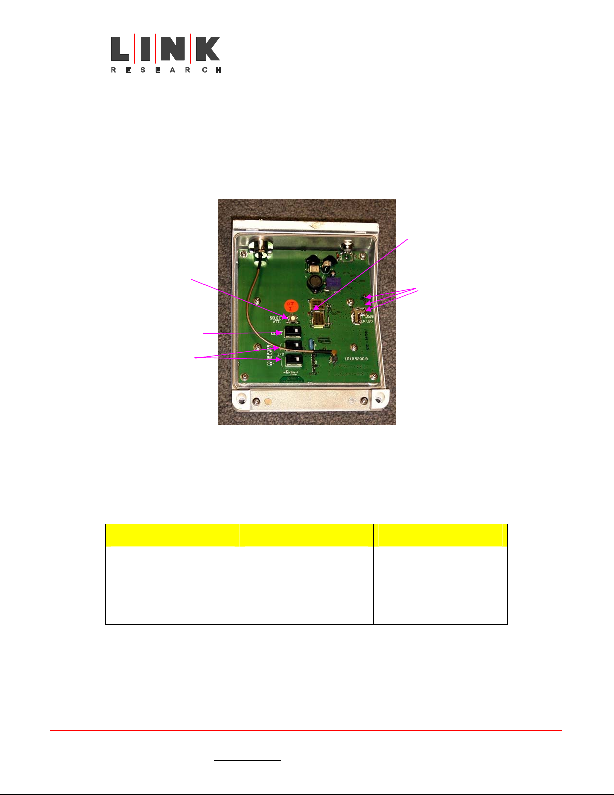
1.2.3 Setting the down convertor attenuation and local
oscillator
Normally, the down convertor gain is preset to a setting chosen for most applications. If
the receiver appears to be overloaded or performance is unsatisfactory, it may be
necessary to alter the setting. To do this it is necessary to open the down convertor casing
by removing the two screws along the top edge.
Once the cover is lifted off, all the switches are freely accessible.
Hi oscillator
running LED
Gain setting
switch S1
Hi/Lo select
switch S2
Attenuation indicating LEDs
3 lit = 30dB attenuation
2 lit = 20dB attenuation
1 lit = 10dB attenuation
0 lit = 40dB attenuation
Address
switches
S3 & S4
Figure 5 – switches and LEDs
inside down convertor
It is not recommended that the attenuation settings for 30dB and 40dB (3 LEDs lit and
no LEDs lit) are used as this has the effect of significantly reducing the signal to noise
ratio.
Switch settings are as follows:
Switch Default setting Description
Gain setting switch S1 Last setting Changes the down convertor
attenuation
Hi/Lo switch S2 Hi (when lit) Selects local oscillator to be
used by the system.
Set to Hi for 2.3 to 2.7GHz
Set to Lo for 1.95 to 2.3GHz
ID switch S3 and S4 User selectable Not currently used
The local oscillator frequency will need to be set to match the correct frequency band.
For frequencies between 1.95GHz and 2.3GHz, set the oscillator in the Lo position (LED not
lit). For frequencies between 2.3GHz and 2.7GHz set the oscillator in the Hi position (LED
lit). This is the default position.
Care needs to be exercised when setting the down convertor attenuation. The main
purpose of the attenuation is to compensate for drop lead cable length, but if incorrectly
set, the attenuation will have an adverse effect on the noise performance and range of the
Link XP L2102/L2104 Receiver Instruction Manual Issue 1 - October 2003 Page 10 of 48
Link Research Ltd. 23/24 Watford Metro Centre, Dwight Road, Watford, Hertfordshire, WD18 9XA, England. Tel: +44 (0) 1923 200 900
Registered in London No. 2074604
Web: www.linkres.co.uk Fax: +44 (0) 1923 241 357

L2102 & L2104 Receiver
Instruction Manual
system. Briefly, with one LED lit, 10dB of attenuation is introduced to protect the front
end of the receiver with reasonably long cable lengths. There is very little difference in
the noise performance of the system. Turning on two LEDs introduces 20dB do attenuation
which will protect the receiver front end with medium cable lengths. The noise
performance is increased slightly and the range of the system may be reduced by up to 30%.
With 3 LEDs switched on 30dB of attenuation is introduced and should only be used for very
short cable lengths. The noise performance of the system can be seriously degraded and
the range reduced by up to 75%. With no LEDs lit, there is no attenuation and this
condition should only be used for very long cables or where the signal is very weak. The
receiver front end has no protection with this setting.
1.2.4 Non-diversity system
This is the simplest system and the receive side only requires 1 antenna and down convertor
to make it work. The performance over short distances will be good, but not as good as a 2
channel diversity system. For outdoor installations where only a small area has to be
covered, non-diversity is ideal.
Generally the antenna should be placed as high as possible and in the clear. See section 2
on antennas for more information.
Connect the receiver as shown in the diagram below. Take care to keep all cables away
from potential sources of interference and/or damage (see section on cables for more
information).
NB When connecting up the cables the receiver should not be powered up. The LNB power
may be active whilst cables are being connected and it is easy to make a short circuit. It is
very unlikely that any damage will be done because the LNB power supply is short circuit
protected, but it is better to be safe than sorry!
Link XP L2102/L2104 Receiver Instruction Manual Issue 1 - October 2003 Page 11 of 48
Link Research Ltd. 23/24 Watford Metro Centre, Dwight Road, Watford, Hertfordshire, WD18 9XA, England. Tel: +44 (0) 1923 200 900
Registered in London No. 2074604
Web: www.linkres.co.uk Fax: +44 (0) 1923 241 357
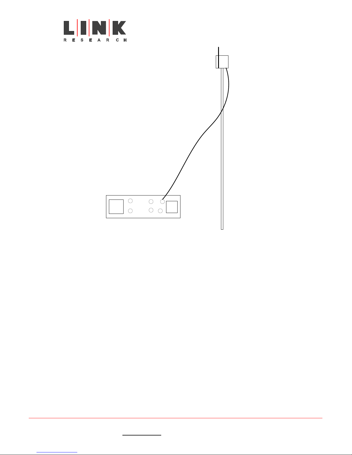
L2102 receiver
Receive antenna
L3010 Down
convertor
75 ohm downlead
L2102 & L2104 Receiver
Instruction Manual
Mast
SDI
Audio
Video
ASI
Frame
Lock
RF1
AC Mains
RF2
Figure 6 – Non-diversity system
Outputs from the receiver can be taken from SDI out or video out or both and audio from
the mulitway connector block or 5 way XLR connector depending on the option fitted. If
required, Frame Lock can be connected to synchronise the output with other equipment.
NB – the colour sub carrier is not locked.
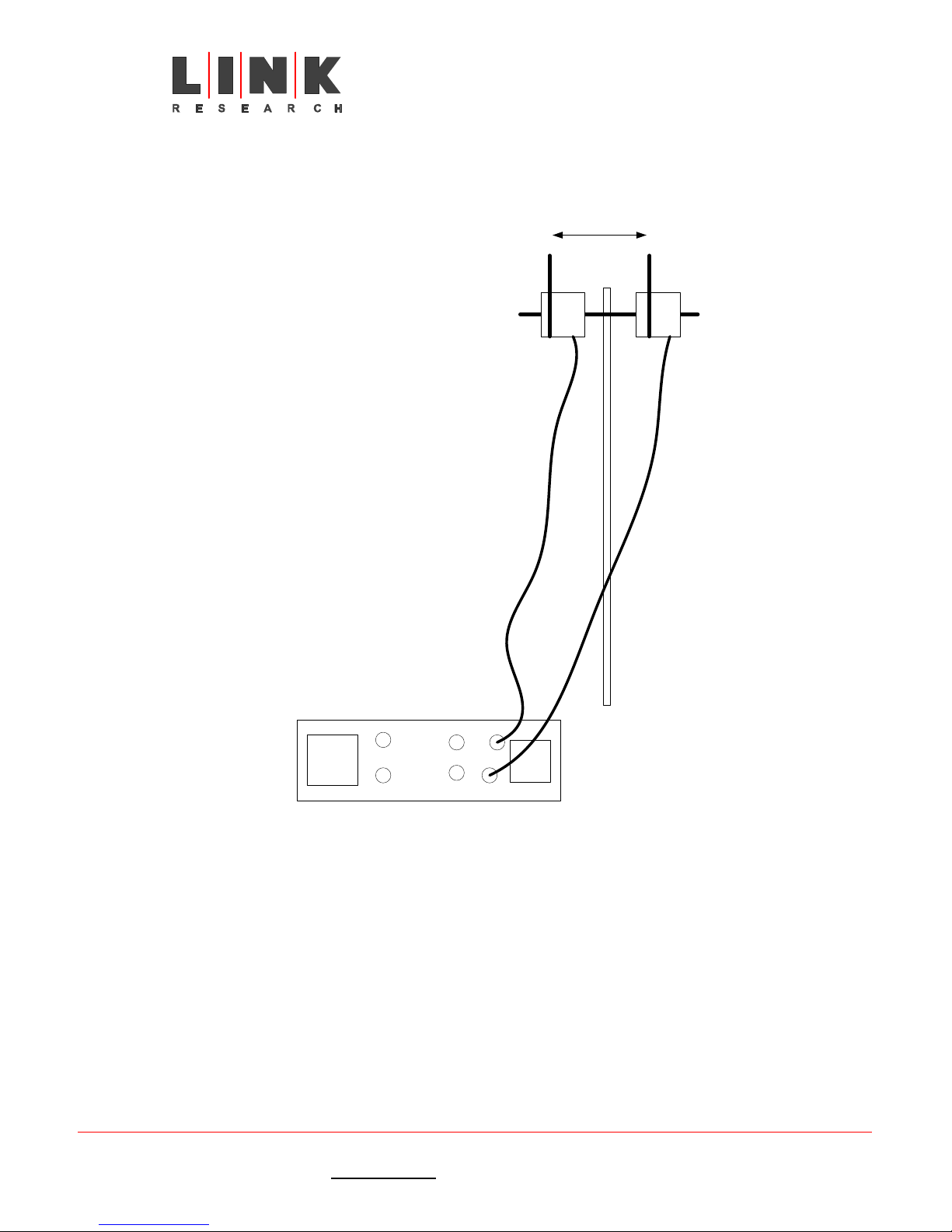
1.2.5 Diversity system
This is a much more robust system giving better performance than non-diversity especially
when the installation is indoors. The transmission range is not increased very much, but
performance near the margins of the transmission area is much more robust and RF “black
holes” are eliminated.
Generally the antennas should be placed as high as possible and in the clear (see section 2
on antennas for more information). The antenna spacing is fairly critical and should be
around 20cm to gain optimum performance. If a greater spacing than 20cm is used, the
full benefits of diversity will not be obtained. A little experimentation may be needed to
find the optimum spacing in a particular environment.
Connect the receive side as shown in the diagram below. Take care to keep all cables away
from potential sources of interference and/or damage (see the section on cables for more
information).
NB When connecting up the cables the receiver should not be powered up. The LNB power
may be active whilst cables are being connected and it is easy to make a short circuit. It is
Link XP L2102/L2104 Receiver Instruction Manual Issue 1 - October 2003 Page 12 of 48
Link Research Ltd. 23/24 Watford Metro Centre, Dwight Road, Watford, Hertfordshire, WD18 9XA, England. Tel: +44 (0) 1923 200 900
Registered in London No. 2074604
Web: www.linkres.co.uk Fax: +44 (0) 1923 241 357
L2102 & L2104 Receiver
Instruction Manual
very unlikely that any damage will be done because the LNB power supply is short circuit
protected, but it is better to be safe than sorry!
Connect the receiver as follows:
20 - 100cm spacing
Receive
antenna
Crossbar
L3010 Down
convertor
75 ohm
downlead
Receive
antenna
L3010 Down
convertor
75 ohm
downlead
Mast
L2102 receiver
SDI
Audio
Video
RF1
RF2
AC Mains
Figure 7 – Diversity system
Outputs from the receiver can be taken from SDI out or video out or both and audio from
the mulitway connector block or 5 way XLR depending on which option is fitted. If required,
a synchronising signal can be input to Frame Lock to synchronise the output with other
equipment.
1.2.6 Dual diversity system
Dual diversity can be used in two different ways. If all four demodulators are set to the
same frequency, one receiver can be used to cover a much greater area. The system could
be set up so that one pair of antennas is inside a stadium covering a sports pitch and the
other pair of antennas is outside the stadium covering the entrances. A single transmitter
can then be used to cover the arrival of a sports team and their entry to the stadium using
Link XP L2102/L2104 Receiver Instruction Manual Issue 1 - October 2003 Page 13 of 48
Link Research Ltd. 23/24 Watford Metro Centre, Dwight Road, Watford, Hertfordshire, WD18 9XA, England. Tel: +44 (0) 1923 200 900
Registered in London No. 2074604
Web: www.linkres.co.uk Fax: +44 (0) 1923 241 357

L2102 & L2104 Receiver
Instruction Manual
the outside antennas and then cover the match using the inside antennas. Movement from
one antenna coverage area to the other will be seamless.
The second way of using dual diversity is to set demodulators 1 and 2 to one frequency and
demodulators 3 and 4 to a second frequency. The system can now be used with two
different camera transmitters. Each camera transmitter will need to have a different
service name (see protocol command list type m) set so that the receiver can select
between them. In this way, it is possible to choose which camera will provide the
receiver’s output. Switching between transmitters will not be seamless as there will be
some disturbance as the source is changed.
Generally the antennas should be placed as high as possible and in the clear (see section xx
on antennas for more information). The antenna spacing is fairly critical and should be
around 20cm to gain optimum performance. If a greater spacing than 20cm is used, the
full benefits of diversity will not be obtained. A little experimentation may be needed to
find the optimum spacing in a particular environment.
Connect the receiver as shown in the diagram below. Take care to keep all cables away
from potential sources of interference and/or damage (see the section on cables for more
information).
NB When connecting up the cables the receiver should not be powered up. The LNB power
may be active whilst cables are being connected and it is easy to make a short circuit. It is
very unlikely that any damage will be done because the LNB power supply is short circuit
protected, but it is better to be safe than sorry!
20 - 100cm spacing
Receive
antenna
L3010 Down
convertor
Fig 8 – dual diversity
system
Receive
antenna
Crossbar
L3010 Down
convertor
20 - 100cm spacing
Receive
antenna
L3010 Down
convertor
Receive
antenna
Crossbar
L3010 Down
convertor
75 ohm
downlead
L2104 receiver
75 ohm
downlead
Mast
SDI
Audio
Video
75 ohm
downlead
RF3
RF4
Mast
RF1
AC Mains
RF2
75 ohm
downlead
1.3 Turning on and setting up the receiver
Link XP L2102/L2104 Receiver Instruction Manual Issue 1 - October 2003 Page 14 of 48
Link Research Ltd. 23/24 Watford Metro Centre, Dwight Road, Watford, Hertfordshire, WD18 9XA, England. Tel: +44 (0) 1923 200 900
Registered in London No. 2074604
Web: www.linkres.co.uk Fax: +44 (0) 1923 241 357

L2102 & L2104 Receiver
Instruction Manual
There is no ON/OFF switch, so plugging in the power cable will turn the receiver on. NB;
connect the antenna cable(s) and L3010(s) before turning the unit on.
Once the unit has booted up, the display screen will look something like the illustration
below.
Figure 9 - top-level menu screen just after boot up
If a valid input signal is present, the amber STATUS indicator will light: if there is no valid
input signal, the red ALARM indicator will be lit.
To enter the menu system, press the button nearest the bottom right corner of the display.
The display will now look something like the illustration below.
Status
LNB ON
Figure 10 - Status menu top level
Press the down arrow until the down unit menu is shown and press enter to select it. Press
the down arrow until the down convertor type menu is displayed. The display will look
something like that shown below.
DConv Type None
Figure 11- down convertor type menu
Pressing the enter key,
• L3010
• Other
• None
Select according to the type of down covertor to be used with the system. Once selected
and confirmed with the enter key,
selected.
Now go back up the menu until the diversity setting menu is displayed.
Link XP L2102/L2104 Receiver Instruction Manual Issue 1 - October 2003 Page 15 of 48
Link Research Ltd. 23/24 Watford Metro Centre, Dwight Road, Watford, Hertfordshire, WD18 9XA, England. Tel: +44 (0) 1923 200 900
Registered in London No. 2074604
Web: www.linkres.co.uk Fax: +44 (0) 1923 241 357
, allows access to the following options:
, the display will change to indicate the type

L2102 & L2104 Receiver
Instruction Manual
Mode Diversity
LNB ON
Pressing the enter key,
, provides a sub menu with the following options:
menu
• Single
• Diversity
• Dual Diversity
• Remux
• Bypass 1
• Bypass 2
• Bypass 3
• Bypass 4
• Test
Figure 12 - Diversity setting
To select the required option, press the enter key,
in the window. Then press the exit key,
, to return to the upper level.
, when the option name is displayed
If a down convertor other than an L3010 has been selected, it will be necessary to go to the
down convertor local oscillator set up page. The display should look something like the
illustration below.
DConvLO 1.8400GHz
LNB ON
Figure 13 - Down convertor
status screen (shown for L3010)
To change the local oscillator setting, press the enter key
and change to the new
value. Press the enter key again to store the new setting and then press the escape key
to return to the Demodulator 1 menu.
NB. It is not possible to use down convertors of mixed manufacture in a diversity
system. The only way this can be done is to select “single” and different local
oscillator values can be entered.
Next, the Input Frequency must be set. At the Demodulator 1 menu, press enter and the
Input Frequency page will be shown and will look something like the illustration below.
- > 2.3950(GHz)
Figure 14 - Frequency changing display
Link XP L2102/L2104 Receiver Instruction Manual Issue 1 - October 2003 Page 16 of 48
Link Research Ltd. 23/24 Watford Metro Centre, Dwight Road, Watford, Hertfordshire, WD18 9XA, England. Tel: +44 (0) 1923 200 900
Registered in London No. 2074604
Web: www.linkres.co.uk Fax: +44 (0) 1923 241 357

L2102 & L2104 Receiver
Instruction Manual
To change the frequency, use the right button to move the block cursor over the number
to be changed and then use the up or down arrows to scroll through the numbers until the
required number appears. To accept and start using the changes, press the enter key
To reject the changes and go back to the top of the frequency menu, press the escape key
.
If the unit is working in Diversity mode, it is not necessary to make settings for
Demodulator 2 as these are automatically carried forward from the Demodulator 1 menu.
When setting up an L2104, it will be necessary to repeat the frequency selection steps
detailed above for demodulator 3. Demodulator 4 will “follow” the settings made in
demodulator 3.
Next, use the down arrow key to select the LNB power menu. The display will look
something like the illustration below.
LNB Power No
Figure 15 – LNB Power Screen
Pressing enter allows two selections to be made:
• Yes
• No
.
Select the required status by pressing enter,
, and the display will be updated to
indicate the status.
When the LNB power is set to on, an LED between the two connectors on the L3010 will be
lit indicating the down convertor is powered (early down convertors do not have this LED
fitted).
The unit should now be locked to the incoming signal. If it is not, go back and check the
settings made above.
Next go to the Decoder menu.
The screen will look something like the illustration below.
Decoder
Figure 16 - Decoder screen
Link XP L2102/L2104 Receiver Instruction Manual Issue 1 - October 2003 Page 17 of 48
Link Research Ltd. 23/24 Watford Metro Centre, Dwight Road, Watford, Hertfordshire, WD18 9XA, England. Tel: +44 (0) 1923 200 900
Registered in London No. 2074604
Web: www.linkres.co.uk Fax: +44 (0) 1923 241 357

L2102 & L2104 Receiver
Instruction Manual
Use the down arrow key until a list of available services is displayed and select the required
service. Press the enter key to confirm the selection.
Now go to the Audio A menu where the current status will be shown and may look
something like the illustration below.
Aaudio O/P Ana
Figure 17 - Channel A audio status
In the illustration above the status is analogue. To change this to digital, press the enter
button,
, select digital and confirm the selection by pressing enter again.
Channel B audio is set up in the say way from the Baudio O/P menu.
If the signal being received is scrambled, it will be necessary to set up the descrambling
menu. To do this select the descrambling menu (6 down arrow presses from Status) and a
screen like the illustration below will be shown.
Figure 18 – Descrambling screen
By using the up or down arrow the following options are available:
• Descrambling Off
• EBS Key “
If EBS Key “ is selected one of the following screens will be displayed:
- >
- > / / / / / / /
The EBS key is an 8 digit hexadecimal number. To enter it, use the up arrow to scroll
through the numbers 1 – 9 and letters A – F. Once the required character has been
selected, use the right arrow key to move the cursor to the next position. Repeat the
Link XP L2102/L2104 Receiver Instruction Manual Issue 1 - October 2003 Page 18 of 48
Link Research Ltd. 23/24 Watford Metro Centre, Dwight Road, Watford, Hertfordshire, WD18 9XA, England. Tel: +44 (0) 1923 200 900
Registered in London No. 2074604
Web: www.linkres.co.uk Fax: +44 (0) 1923 241 357
Screen when no previous
EBS key has been entered
Screen when a previous
EBS key has been entered
Figure 19 – EBS key change screens

L2102 & L2104 Receiver
Instruction Manual
selection process until the next character is shown. Once the complete key is displayed,
press the enter key,
, to store this in memory.
NB. It is possible to select characters outside the range of 1 – 9 and A – F, but such a
selection will be rejected when the enter key is pressed.
Once the receiver is set up, go to the Status menu and press enter,
, and a screen like
the illustration below will be displayed.
Figure 20 – Signal quality status display (L2102)
The bar graphs give an indication of the relative signal quality of the decoded MPEG
packets. In operation it is quite normal that the bar graphs fluctuate wildly.
If the receiver is to be powered off, the settings will be retained in the current memory.
When powered up again, it will use these settings unless another memory is recalled to the
current memory. It is therefore good practice to save the set up to one of the nine
memories so that it can be recalled easily. To do this, enter the Memory menu (one down
from Status). The top-level screen will look something like the illustration below:
Memory
Figure 21 – Memory menu top level
Press the enter key and the screen display will change:
Store - Config ?
Figure 22 - Store config screen
Press the enter key and the screen will change again to:
->Config ?
Figure 23 – Second level of storing a configuration
Link XP L2102/L2104 Receiver Instruction Manual Issue 1 - October 2003 Page 19 of 48
Link Research Ltd. 23/24 Watford Metro Centre, Dwight Road, Watford, Hertfordshire, WD18 9XA, England. Tel: +44 (0) 1923 200 900
Registered in London No. 2074604
Web: www.linkres.co.uk Fax: +44 (0) 1923 241 357

L2102 & L2104 Receiver
Instruction Manual
Pressing the down arrow scrolls through the numbers 1 – 9 and the up arrow 9 – 1. Once the
desired memory is selected, press the enter key and all the settings will be stored for easy
recall.
To recall a previously stored configuration, go to the Memory menu, press enter and then
use the down arrow to select the Load config option. The screen will look something like
the illustration below:
Load - Config ?
Figure 24 – The load config screen
Press enter and the display will change to something like the illustration below:
->Config ?
Figure 25 - Configuration selection screen
By using the down arrow, memory locations from 1 – 9 can be selected. Using the up arrow
allows memory location selection from 9 – 1. Once the desired memory has been selected,
pressing,
, will store the setup data in that location.
Link XP L2102/L2104 Receiver Instruction Manual Issue 1 - October 2003 Page 20 of 48
Link Research Ltd. 23/24 Watford Metro Centre, Dwight Road, Watford, Hertfordshire, WD18 9XA, England. Tel: +44 (0) 1923 200 900
Registered in London No. 2074604
Web: www.linkres.co.uk Fax: +44 (0) 1923 241 357

L2102 & L2104 Receiver
Instruction Manual
Section 2 – More Advanced
Operation
2.1 Antennas
A good understanding of how antennas work and their limitations is necessary to maximise
the performance of the LinkXP L2102/2104 receivers. The COFDM modulation method used
has a big advantage of being immune to multipath propagation. As a result the antenna
requirements are very different to those for analogue systems which rely heavily on
directional antennas to get good performance. The following section gives some good
background information with some practical examples of antenna setup.
2.1.1 The receive antenna
The requirements for the receive antenna are rather difficult. Normally these antennas
will be located on the edge of the area of activity and will “look” inwards. It is therefore
advantageous if their performance can take advantage of this by only taking signals from
their “front”. In analogue systems this can be done by building Yagi arrays or using horn
type antennas that are very directional and give good performance because they reduce the
effect of multiple path signals by eliminating them. If the transmitter is moving, there
must be an operator to steer the receive antenna so that it tracks the transmitter
accurately. Any mismatch between the paths will result in complete signal loss or partial
break-up of the picture if the signal is on the beam margin. In reality, there are probably
several hundred reflected signals that result in nulls in the received signals.
In a digital system, especially a system using COFDM, much of the performance gain comes
from using multipath reception. As a result there is no need for an operator to track the
transmitter: a fixed antenna works as well because the receiver uses the multipart or
reflected propagation to rebuild the signal.
Reflective
object
Reflected signals
Reflective object
Multipath null
Transmitter Receiver
The vertical beamwidth of the receive antenna needs to be fairly high and for a football or
sports stadium, 80º will be very effective. If this can be combined with a horizontal
Link XP L2102/L2104 Receiver Instruction Manual Issue 1 - October 2003 Page 21 of 48
Link Research Ltd. 23/24 Watford Metro Centre, Dwight Road, Watford, Hertfordshire, WD18 9XA, England. Tel: +44 (0) 1923 200 900
Registered in London No. 2074604
Web: www.linkres.co.uk Fax: +44 (0) 1923 241 357
Direct signal
Reflected signal
Reflctive ogject
Figure 26 – multipath signals and the null zone

L2102 & L2104 Receiver
Instruction Manual
beamwidth of around 107º this would suit most applications. Such an antenna would be
described as having +6dBi gain. The polar diagrams of such an antenna are shown below.
Figure 27 - Polar plots for ideal receive antenna with +6dBi
Vertical on the left and horizontal on the right
One such antenna should give good coverage of a sports stadium if mounted as shown in the
diagram below;
Likely area of coverage
Figure 28 – mounting a single antenna in a stadium
Mounted in this way, the antenna will be able to “see” virtually all the stadium except
perhaps the two corners nearest to it.
2.1.2 Diversity antennas
Link XP L2102/L2104 Receiver Instruction Manual Issue 1 - October 2003 Page 22 of 48
Link Research Ltd. 23/24 Watford Metro Centre, Dwight Road, Watford, Hertfordshire, WD18 9XA, England. Tel: +44 (0) 1923 200 900
Registered in London No. 2074604
Web: www.linkres.co.uk Fax: +44 (0) 1923 241 357
Mount receive antenna in
this region

L2102 & L2104 Receiver
Instruction Manual
Using diversity antennas, considerable performance gains can be made in a number of
ways. The classical deployment of diversity antennas requires two antennas to be mounted
11 x ¼λ apart. For a transmitter operating at 2.5GHz the theoretical spacing is around
33cm, but good results can be obtained by using spacings varying between 20cm up to 2
metres. If it proves difficult to arrange this, greater spacing can be used with very good
effect. It pays to experiment with different spacings and positions to get the best results.
The performance of the system may vary when a stadium is empty from when it has a full
crowd in it.
Using the example shown in figure xx above, the two antennas would be mounted side-byside near the centre line and high up in the stadium structure.
Diversity reception is not just confined to two antennas. By using a Link 2104 receiver, up
to 4 antennas can be used and the receiver will take the best signal to build its output.
This has considerable advantages if the camera is required to track players’ progress from
the dressing room down the tunnel and out onto the pitch. By placing antennas in the
dressing room, half way down the tunnel and in the normal positions for covering the pitch,
excellent results can be achieved.
Figure 29 – Link L3010 with
complimentary directional antenna
mounted on the front
2.1.3 LinkXP and other Manufacturers’ antennas
The LinkXP wireless camera system will work with antennas of non-Link manufacture, but
as many of these are based on lossy printed circuit elements and thin coaxial cable,
performance may be disappointing.
2.1.4 Mounting antennas
Five general rules should be applied to all antenna installations:
• Mount antennae as high as possible. A couple of metres can make a considerable
difference.
Link XP L2102/L2104 Receiver Instruction Manual Issue 1 - October 2003 Page 23 of 48
Link Research Ltd. 23/24 Watford Metro Centre, Dwight Road, Watford, Hertfordshire, WD18 9XA, England. Tel: +44 (0) 1923 200 900
Registered in London No. 2074604
Web: www.linkres.co.uk Fax: +44 (0) 1923 241 357

L2102 & L2104 Receiver
Instruction Manual
• Keep antennae in the clear especially the transmit antenna. The human body is 80%
water and is a good RF attenuator so the antenna should be above head height to
be most effective. Although COFDM relies on reflections, the receive antenna
needs enough clear space to be able to “see” the different radiation paths.
• Test a number of different locations. On the day of the live transmission, the RF
characteristics of the environment may have changed significantly e.g. a stadium
with a capacity crowd is very different to when it is empty.
• Use only good quality cables and keep them as short as possible so that maximum
signal is available.
• For Diversity and Dual Diversity installations, pairs of antennas should be spaced
20cm apart for optimum performance.
It is most likely that LinkXP will be used in temporary locations so jubilee clips, cable tie
wraps, gaffer tape etc are likely to be used. So long as the antennae are held firmly and
vertically, they should work well.
2.1.5 A some practical examples
Example 1
The requirement was for coverage of a rugby final in a national stadium. The Director
wanted the following:
• Coverage of the pitch for all the match action and the pre-match entertainment
• Pictures of the teams in the changing rooms before the match, during the interval
and after the game
• Pictures of the teams leaving the dressing rooms and running down the tunnel onto
the pitch. (The tunnel was about 100 metres long and underneath the main stand).
• Touchline cover of the match and close-ups of interesting incidents
• Close-ups of the celebrities in the main stand
• On pitch post match celebrations and interviews
It was decided to use 3 antennae to give coverage of the event. No permanent cabling was
available so cables had to be run in specially in a very limited time. Antennae were
mounted vertically on microphone stands about 1.7metres above ground level giving good
horizontal omni directional coverage. Locations of the antennae were as follows:
• One near the corner flag
• One near the tunnel entrance adjacent to the pitch
• One at the end of the tunnel near the changing rooms
Link XP L2102/L2104 Receiver Instruction Manual Issue 1 - October 2003 Page 24 of 48
Link Research Ltd. 23/24 Watford Metro Centre, Dwight Road, Watford, Hertfordshire, WD18 9XA, England. Tel: +44 (0) 1923 200 900
Registered in London No. 2074604
Web: www.linkres.co.uk Fax: +44 (0) 1923 241 357

L2102 & L2104 Receiver
Instruction Manual
Limit of RF coverage
Pitch
Antenna 3
Tunnel
Antenna 1
Dressing
room
Antenna 2
OB truck
Dressing
room
Figure 30 – Coverage at Stadium Australia
During the broadcast QPSK modulation was used for coverage in the tunnel and changing
rooms using Antenna 1 and Antenna 2 for diversity. During the match the modulation was
switched to 16QAM using Antenna 2 and Antenna 3 in diversity. For the post match
interviews, the video input was changed from YUV to SDI with embedded sound.
Post match debrief found the following points of interest:
• Antennae need to be mounted as high as possible and would have given a bigger
area of RF coverage.
• Temporary antenna mountings need to be away from potential crowd tampering
• Cables from down convertors to receiver can be up to 300 metres if using the
correct type of cable
• The distance between antennae is not critical for diversity reception.
• It is a great advantage to be able to try out a number of alternative antenna
locations to determine optimum performance positions
Example 2
The requirement was for coverage of a major international yachting event. The Director
wanted the following:
• Coverage of start and finish of races
• Close-ups of individual boats during races
• General shots around the marina
• Interviews with celebrities in boats and in the clubhouse
Some programme material was filmed and edited during the day, but the majority of the
material was to be used for live national broadcast during sports programmes.
The event was covered by an OB truck parked on the quayside with a marina in front of it.
The marina was protected by a harbour wall separating the mooring area from the racing
Link XP L2102/L2104 Receiver Instruction Manual Issue 1 - October 2003 Page 25 of 48
Link Research Ltd. 23/24 Watford Metro Centre, Dwight Road, Watford, Hertfordshire, WD18 9XA, England. Tel: +44 (0) 1923 200 900
Registered in London No. 2074604
Web: www.linkres.co.uk Fax: +44 (0) 1923 241 357

L2102 & L2104 Receiver
Instruction Manual
area. To the rear was an open space flanked by a built up area of boathouses, warehouses
and general buildings. Very few line-of-sight propagation paths existed.
The two antennae were mounted on a crossbar on the top of a 7-metre pump up mast.
Initially they were left hanging below the bar so that they were in free space. However, it
was found that the wind disturbed them too much so they were firmly fixed onto the
crossbar alongside other existing antennae.
The cameraman was based in a small rigid inflatable dingy and moved freely around the
water both in and out of the marina. Live coverage of racing was reliably achieved at
distances of up to 1½km. Interviews were held both inside and outside the clubhouse.
Figure 31 – Link directional antennas in diversity rig
Start and finish area
for races
C
l
u
b
h
o
u
s
e
y
t
t
e
J
Event display
Marina
OB van
Boathouse
Position of
antennas
OFFICES AND WAREHOUSES
Open area
Figure 32 – Layout of harbour area for yachting event
Link XP L2102/L2104 Receiver Instruction Manual Issue 1 - October 2003 Page 26 of 48
Link Research Ltd. 23/24 Watford Metro Centre, Dwight Road, Watford, Hertfordshire, WD18 9XA, England. Tel: +44 (0) 1923 200 900
Registered in London No. 2074604
Web: www.linkres.co.uk Fax: +44 (0) 1923 241 357

2.2 Cables
L2102 & L2104 Receiver
Instruction Manual
Figure 33 – Link
omnidirectional receive
antenna mounted on L3010
down convertor
2.2.1 Why should I be concerned about cables?
Wireless camera systems use very low power transmissions with a maximum effective
radiated power of around 100mW. To make the most of this, it is vital that the correct
cable types are used and that they are treated with respect. A damaged cable of the
correct type may give inferior performance to good cable of the wrong type and both will
provide less than acceptable results.
2.2.2 Cable impedances
Two different cable impedances are used in wireless camera systems. The transmit system
will use 50Ω coaxial cable and the receive system will use 75Ω cable. It is vital that the
two cable types are not mixed up or system performance may be disappointing.
As supplied, Link receivers do not require the use of any 50Ω cable because the connection
between the receive antenna and the down convertor is made by using N-type elbow
connectors. However, if these are lost or become damaged, a short 50Ω coaxial link with
N-type connectors can be made up. The length of this link should not excede15cm to avoid
unnecessary signal losses.
2.2.3 Cable losses
Link XP L2102/L2104 Receiver Instruction Manual Issue 1 - October 2003 Page 27 of 48
Link Research Ltd. 23/24 Watford Metro Centre, Dwight Road, Watford, Hertfordshire, WD18 9XA, England. Tel: +44 (0) 1923 200 900
Registered in London No. 2074604
Web: www.linkres.co.uk Fax: +44 (0) 1923 241 357
L2102 & L2104 Receiver
Instruction Manual
Besides the characteristic impedance, cables are measured on the losses they incur as the
signal passes along them. Therefore the lower the cable losses, the greater the cable
length that can be used. To get the best performance from the Link receivers, only low
loss cables must be used. Whilst these are more expensive than lossy cable, the
performance gain is worth the extra cost.
Low loss cables generally have a foam dielectric whereas more lossy cables have a solid
dielectric. Also low loss cables usually have more copper in their conductors than lossy
cables.
The cable from the down convertor to the receiver is the most critical in terms of loss
because this is normally required to be 10s of metres long. The maximum loss that can be
tolerated on this cable length is 43dB. To find out what this equates to in the real world,
look up the attenuation per 10 metres at 900MHz in the manufacture’s data tables.
Dividing this figure into 43dB will give the maximum cable length in 10s of metres.
2.2.4 Cable types
Ideally the receive antenna should be mounted directly on the down convertor (see figure
31). Where this is not possible, the shortest length of cable should be used to minimise the
losses. A low loss heliax such as Andrew type LDF450 should be used. This is a ½” thick
cable using foam dielectric and solid copper outer. Other similar low loss thick cable can
be used.
For the cable between the down convertor and the receiver, a low loss foam dielectric such
as Comscope RG59 or RG11 should be used. Using these cables will allow a 200 metre run
with RG59 and 300 metres with RG11.
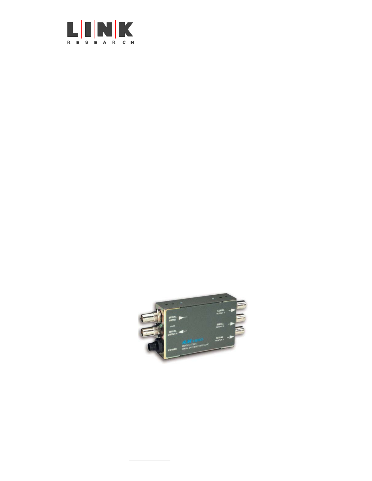
Where the output from the receiver is SDI and cable lengths of greater than 5 metres are to
be used a line driver will be required to equalise the signal on the cable. This will allow
cable lengths of up to 300 metres to be used. A suitable line driver is the AGA video type
D5DA as shown in the illustration below.
Only use cables whose electrical characteristics and type numbers are known. Other
cables may give poor performance at best.
Figure 34 – AJA video line driver type D5DA
Link XP L2102/L2104 Receiver Instruction Manual Issue 1 - October 2003 Page 28 of 48
Link Research Ltd. 23/24 Watford Metro Centre, Dwight Road, Watford, Hertfordshire, WD18 9XA, England. Tel: +44 (0) 1923 200 900
Registered in London No. 2074604
Web: www.linkres.co.uk Fax: +44 (0) 1923 241 357

L2102 & L2104 Receiver
Instruction Manual
2.2.5 Care of cables
Using the correct type of cable is still no guarantee of success if the cables are not given
the care and respect they require. The worst enemy of coaxial cables is moisture. Any
ingress of moisture will physically degrade the cable causing corrosion that will change the
cable’s characteristic impedance. All terminations must therefore be sealed against water
penetration and any cable whose outer sheath is damaged should be thrown away. For any
cable that is used outside, it is advisable to fit waterproof boots to the terminations to
prevent water getting into the cable dielectric.
When not in use, cables should be coiled on drums or in a figure-of-eight to equalise the
stresses on the cable construction and terminations should be capped to prevent damage to
the connector as well as moisture ingress.
When installing cables either permanently or temporarily two simple rules should be
followed:
• Do not place pressure on the cable (cable ties too tight or heavy objects holding it
down) as this deforms the dielectric causing a change in characteristic impedance
leading to standing waves being generated over the cable length.
• Do not bend cable round too tight a radius at corners. General rule of thumb is
that the minimum radius of the bend should not be less than 6 times the diameter
of the cable. For example an RG59 having a nominal diameter of 6mm should not
be formed into a radius of less than 36mm.
2.3 The Receiver
2.3.1 The Receiver Menu Structure
The diagram below shows the function of the front panel controls and displays necessary to
operate the receiver.
IR remote control
sensor
LED indicators
Liquid crystal
display
STATUS
ALARM
POWER
Exit button
L2100 DIVERSITY IRD - Ultra Low Delay
CJM2 Technology
Enter
button
Figure 35 – Controls and displays
Left
button
Up button
Down
button
Right
button
Link XP L2102/L2104 Receiver Instruction Manual Issue 1 - October 2003 Page 29 of 48
Link Research Ltd. 23/24 Watford Metro Centre, Dwight Road, Watford, Hertfordshire, WD18 9XA, England. Tel: +44 (0) 1923 200 900
Registered in London No. 2074604
Web: www.linkres.co.uk Fax: +44 (0) 1923 241 357

L2102 & L2104 Receiver
Instruction Manual
Default values are shown in bold. # indicates a value derived from the setting or
entered by the User.
Top level
menu
Status
Memory
Sub menu Options Comments
None
None
Bar graph like display for each RF
input indicating received packet
quality. The nearer the display is to
the right, the greater the number of
good packets received. It is very
common for the display to fluctuate
widely and the receiver will operate
correctly with very low status values.
Store – Config?
Config 1 Stores the current settings into
memory location 1.
Config 2 Stores the current settings into
memory location 2.
Config 3 Stores the current settings into
memory location 3.
Config 4 Stores the current settings into
memory location 4.
Config 5 Stores the current settings into
memory location 5.
Config 6 Stores the current settings into
memory location 6.
Config 7 Stores the current settings into
memory location 7.
Config 8 Stores the current settings into
memory location 8.
Config 9 Stores the current settings into
memory location 9.
Load – Config?
Config 1 Loads stored settings from memory
location 1.
Config 2 Loads stored settings from memory
location 2.
Config 3 Loads stored settings from memory
location 3.
Config 4 Loads stored settings from memory
location 4.
Config 5 Loads stored settings from memory
location 5.
Config 6 Loads stored settings from memory
location 6.
Config 7 Loads stored settings from memory
location 7.
Config 8 Loads stored settings from memory
location 8.
Config 9 Loads stored settings from memory
location 9.
Default Restore No
No Does not change the current active
settings.
Yes Restores the current active settings
to factory defaults.
NB – If the receiver cannot be set up,
it is worth using this option and then
restarting the set-up again.
Link XP L2102/L2104 Receiver Instruction Manual Issue 1 - October 2003 Page 30 of 48
Link Research Ltd. 23/24 Watford Metro Centre, Dwight Road, Watford, Hertfordshire, WD18 9XA, England. Tel: +44 (0) 1923 200 900
Registered in London No. 2074604
Web: www.linkres.co.uk Fax: +44 (0) 1923 241 357

L2102 & L2104 Receiver
Instruction Manual
Last Config # None Last configuration (memory) used.
OFDM Demod
1*
IPFreq #.###GHz
DConvLO #.###GHz
LoSide Low
Width #MHz
Guard ???
Lock ##
Modulation ??? None Automatically detected from the
Carrier ??? None Automatically detected from the
None
The transmit frequency of the
camera transmitter is entered here.
Note that although tuning steps of
10kHz can be entered on the screen,
when the enter key is pressed the
turner locks to the nearest 125kHz
step.
If the down convertor settings in the
Unit menu are set to L3010 or L3020
(Link), the frequency is
automatically copied to the OFDM
Demod 2 menu. If the down
convertor setting is set to Other, a
frequency can be entered that does
not have to be the same as in OFDM
Demod 2.
None
The down convertor local oscillator
frequency is entered here. Where
Link down convertors are being used,
the figure is automatically entered
from a menu setting in the Unit
menu. For down convertors from
other manufacturers enter the local
oscillator frequency here: see
supporting documentation for
details.
High
Selects the local oscillator output
mix for the down convertor. Used
with Link down convertors.
Low
Selects the local oscillator output
mix for the down convertor. Used
with other manufacturers’ down
convertors. See supporting
documentation.
8MHz
Channel bandwidth. Check with
local RF Authorities for appropriate
regulations.
7MHz
Channel bandwidth. Check with
local RF Authorities for appropriate
regulations.
6MHz
Channel bandwidth. Check with
local RF Authorities for appropriate
regulations.
None
Automatically picked up from the
incoming signal. When a value is
displayed here, it is an indication
that the receiver is locked to an
incoming signal.
No Automatically detected: the receiver
is not locked to any incoming signal.
Yes Automatically detected: the receiver
is locked to an incoming signal.
incoming signal.
incoming signal.
Link XP L2102/L2104 Receiver Instruction Manual Issue 1 - October 2003 Page 31 of 48
Link Research Ltd. 23/24 Watford Metro Centre, Dwight Road, Watford, Hertfordshire, WD18 9XA, England. Tel: +44 (0) 1923 200 900
Registered in London No. 2074604
Web: www.linkres.co.uk Fax: +44 (0) 1923 241 357

OFDM Demod
1*
OFDM Demod
2*
L2102 & L2104 Receiver
Instruction Manual
FEC Rate ??? None Automatically detected from the
incoming signal.
Polarity ??? None Automatically detected from the
incoming signal.
SNR #.####dBm
None
Signal to noise ratio automatically
detected from the incoming signal.
The reading shown is an
instantaneous measurement taken at
the time the return key is pressed.
To update the reading, the menu
must be exited and then re-entered.
MER #.####dBm
None
Modulation error rate automatically
detected from the incoming signal.
The reading shown is an
instantaneous measurement taken at
the time the return key is pressed.
To update the reading, the menu
must be exited and then re-entered.
PreBER #####.####e
None
Pre viterbi error rate automatically
detected from the incoming signal.
The reading shown is an
instantaneous measurement taken at
the time the return key is pressed.
To update the reading, the menu
must be exited and then re-entered.
PostBER #####.####
None
Post viterbi error rate automatically
detected from the incoming signal.
The reading shown is an
instantaneous measurement taken at
the time the return key is pressed.
To update the reading, the menu
must be exited and then re-entered.
Pkt Errs #.####
None
Packet errors automatically detected
from the error corrected data
stream. The reading shown is an
instantaneous measurement taken at
the time the return key is pressed.
To update the reading, the menu
must be exited and then re-entered.
IPFreq #.###GHz
None
The transmit frequency of the
camera transmitter is entered here.
Note that although tuning steps of
10kHz can be entered on the screen,
when the enter key is pressed the
turner locks to the nearest 125kHz
step.
If the down convertor settings in the
Unit men are set to L3010 or L3020
(Link), the frequency is
automatically copied from the OFDM
Demod 1 menu. If the down
convertor setting is set to Other, a
frequency can be entered that does
not have to be the same as in OFDM
Demod 1.
DConvLO #.###GHz
None
The down convertor local oscillator
frequency is entered here. Where
Link down convertors are being used,
Link XP L2102/L2104 Receiver Instruction Manual Issue 1 - October 2003 Page 32 of 48
Link Research Ltd. 23/24 Watford Metro Centre, Dwight Road, Watford, Hertfordshire, WD18 9XA, England. Tel: +44 (0) 1923 200 900
Registered in London No. 2074604
Web: www.linkres.co.uk Fax: +44 (0) 1923 241 357

OFDM Demod
2*
L2102 & L2104 Receiver
Instruction Manual
the figure is automatically entered
from a menu setting in the Unit
menu. For down convertors from
other manufacturers enter the local
oscillator frequency here: see
supporting documentation for
details.
LoSide Low
High
Low
Selects the local oscillator output
mix for the down convertor. Used
with Link down convertors.
Selects the local oscillator output
mix for the down convertor. Used
with other manufacturers’ down
convertors. See supporting
documentation.
Width #MHz
8MHz
7MHz
Channel bandwidth. Check with
local RF Authorities for appropriate
regulations.
Channel bandwidth. Check with
local RF Authorities for appropriate
regulations.
6MHz
Channel bandwidth. Check with
local RF Authorities for appropriate
regulations.
Guard ???
None
Automatically picked up from the
incoming signal. When a value is
displayed here, it is an indication
that the receiver is locked to an
incoming signal.
Lock ##
No Automatically detected: the receiver
is not locked to any incoming signal.
Yes Automatically detected: the receiver
is locked to an incoming signal.
Modulation ??? None Automatically detected from the
incoming signal.
Carrier ??? None Automatically detected from the
incoming signal.
FEC Rate ??? None Automatically detected from the
incoming signal.
Polarity ??? None Automatically detected from the
incoming signal.
SNR #.####dBm
None
Signal to noise ratio automatically
detected from the incoming signal.
The reading shown is an
instantaneous measurement taken at
the time the return key is pressed.
To update the reading, the menu
must be exited and then re-entered.
MER #.####dBm
None
Modulation error rate automatically
detected from the incoming signal.
The reading shown is an
instantaneous measurement taken at
the time the return key is pressed.
To update the reading, the menu
must be exited and then re-entered.
Pre viterbi error rate automatically
detected from the incoming signal.
The reading shown is an
Link XP L2102/L2104 Receiver Instruction Manual Issue 1 - October 2003 Page 33 of 48
Link Research Ltd. 23/24 Watford Metro Centre, Dwight Road, Watford, Hertfordshire, WD18 9XA, England. Tel: +44 (0) 1923 200 900
Registered in London No. 2074604
Web: www.linkres.co.uk Fax: +44 (0) 1923 241 357

OFDM Demod
3*
OFDM Demod
4*
Decoder
L2102 & L2104 Receiver
Instruction Manual
PreBER #####.####e None instantaneous measurement taken at
the time the return key is pressed.
To update the reading, the menu
must be exited and then re-entered.
PostBER #####.####
None
Post viterbi error rate automatically
detected from the incoming signal.
The reading shown is an
instantaneous measurement taken at
the time the return key is pressed.
To update the reading, the menu
must be exited and then re-entered.
Pkt Errs #.####
None
Packet errors automatically detected
from the error corrected data
stream. The reading shown is an
instantaneous measurement taken at
the time the return key is pressed.
To update the reading, the menu
must be exited and then re-entered.
Demod 3 and 4 work in the same way
as Demod 1 and 2.
Demod 3 and 4 work in the same way
as Demod 1 and 2.
Service ######
List of
available
services
Shows the service name of the
service to which the receiver is
currently locked. Pressing enter
brings up a list of available services
which can be scrolled through.
Pressing enter selects the new
service. If the receiver is not locked
No Service is displayed and a DEC
error warning flashes on the display.
Default ‘#####’ Service 01 Enables the setting of the service the
receiver will automatically lock onto.
625 Video PAL
PAL Sets the composite output for 625-
line video standard.
YUV Sets the component output for 625-
line video standard.
525 Video NTSC
YUV Sets the component output for 525-
line video standard.
NTSC No
Ped
Sets the composite output for 525line video standard. No pedestal is
placed on the black level.
NTSC Sets the composite output for 525-
line video standard. A 12½ IRE
pedestal is put on the black level.
PAL ITS ###
Off In picture test signal. For
engineering use only.
CCIR In picture test signal. For
engineering use only.
UK In picture test signal. For
engineering use only.
BBC1 In picture test signal. For
engineering use only.
BBC2 In picture test signal. For
engineering use only.
Off In picture test signal. For
engineering use only.
Link XP L2102/L2104 Receiver Instruction Manual Issue 1 - October 2003 Page 34 of 48
Link Research Ltd. 23/24 Watford Metro Centre, Dwight Road, Watford, Hertfordshire, WD18 9XA, England. Tel: +44 (0) 1923 200 900
Registered in London No. 2074604
Web: www.linkres.co.uk Fax: +44 (0) 1923 241 357

Decoder
Multiplexer
RS232 Data
NTSC ITS ###
Audio DID ###
Framelock ###
Offset #####pix
Locked ###
Pwr Up Line Std ###
Fail mode ######
ASI OP ### byte
Bitrate ##.#####Mbi
Baudrate ####
L2102 & L2104 Receiver
Instruction Manual
NTC In picture test signal. For
engineering use only.
FCC In picture test signal. For
engineering use only.
Ana Sets Audio A output to analogue. Aaudio O/P ###
Dig Sets Audio A output to digital.
Ana Sets Audio B output to analogue. Baudio O/P
Dig Sets Audio B output to digital.
None
Allows the audio data identifier for
embedded audio to be changed.
Default value is 767.
Off The unit is free running and not
locked to any external source.
On
The unit’s video is frame locked to
an external source and will be
slightly delayed. If Framelock is set
to on and no synchronising input is
detected, an alarm, GEN, flashes on
the display.
NB – the colour sub carrier is not
locked to the synchronising source.
None
Allows delay or advance of the
framelock in the range of 0 – 9999
pixels. 5000 is the centre of the
range. 1 pixel = approx 74.63 nano
seconds.
None
Shows when the receiver is locked to
a valid input signal. Yes or No will
be displayed according to the status.
625 Sets the output video standard to
625 lines at power up.
525 Sets the output video standard to
525 lines at power up.
Freeze
If the input to the receiver is lost,
the last good frame of video is
displayed.
Blue If the input to the receiver is lost, a
blue screen is displayed.
188
Sets the ASI output to 188 byte
packets (no Reed Solomon error
correction is added).
204
Sets the ASI output to 204 byte
packets by adding Reed Solomon
error correction.
None
This sets the overall bit rate for the
receiver so the figure must be set to
accommodate the data stream
passing through. It does not matter
if the bit rate is set too high.
This setting should be used to limit
the ASI output bit rate where the
output signal is being fed to a
downstream multiplexer.
Off Inhibits any RS232 data being output. Data ###
On Allows RS232 data to be output.
None
Automatically detects the baud rate
of the data stream. If no data is
Link XP L2102/L2104 Receiver Instruction Manual Issue 1 - October 2003 Page 35 of 48
Link Research Ltd. 23/24 Watford Metro Centre, Dwight Road, Watford, Hertfordshire, WD18 9XA, England. Tel: +44 (0) 1923 200 900
Registered in London No. 2074604
Web: www.linkres.co.uk Fax: +44 (0) 1923 241 357
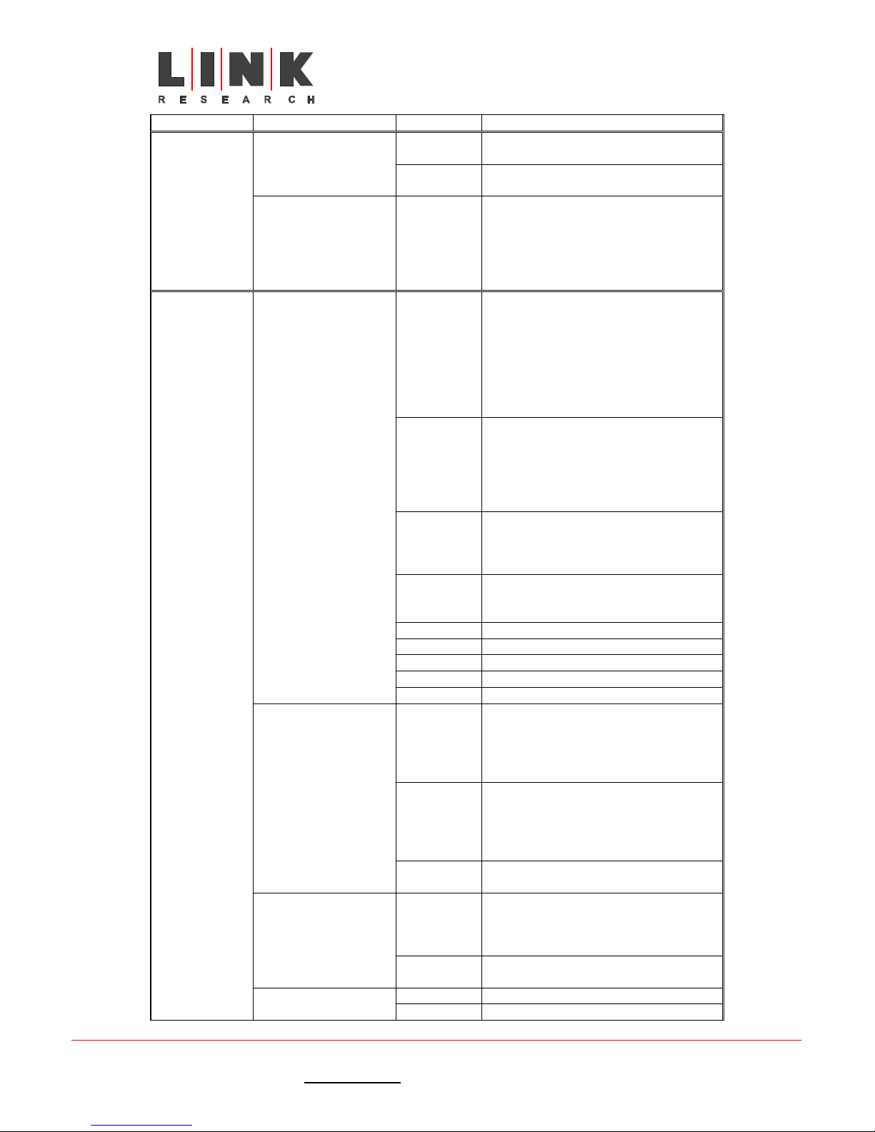
L2102 & L2104 Receiver
Instruction Manual
detected, (null) is displayed.
Descrambling
Descrambling ###
EBS Key ‘’
Off An encrypted data stream will not be
decrypted.
EBS Enables decryption of and EBS
encrypted data stream.
None Enables entry of an 8 digit
hexadecimal key. The left and right
arrows allow scrolling to the left or
right in the number. The up and
down arrows enable scrolling through
the values 1 – 9 and A – F.
Unit
Mode ######
Dconv Type #####
LNB Power ###
Single
Diversity
Dual
Diversity
Remux
Bypass 1 For engineering use only.
Bypass 2 For engineering use only.
Bypass 3 For engineering use only.
Bypass 4 For engineering use only.
Test For engineering use only.
L3010
Other
None With this setting, the receiver can be
Yes
No There is no low voltage power
ASI Sets ASI as the output.
Selects DVB-T modulation as the
Use this setting for a single antenna
connected to RF1.
NB – this setting is only suitable for
very short ranges where the
transmitter is static. If the
transmitter is moving around, there
may be breaks in transmission due to
flat fading of the signal.
Two antennas are connected, one to
RF1 and one to RF2. RF3 and RF4
can also be connected in the same
way. This gives the most reliable
performance because it is not
affected by flat fading.
Four antennas are connected, one
each to RF1, RF2, RF3 and RF4.
This acts as two independent
diversity systems.
Where more than services are input,
they can be remuxed together to
create a single output stream.
Use this setting for a Link
manufactured down convertor. This
setting automatically enters the
correct local oscillator frequency in
the Demod menus
Use this setting for other
manufacturers down convertors. The
local oscillator setting must be
manually entered in the Demod
menus.
directly tuned to any UHF frequency.
Power is supplied via the downleads
to the down convertor. On the
display LNB ON is shown in the
bottom left corner.
supplied to the down leads.
Link XP L2102/L2104 Receiver Instruction Manual Issue 1 - October 2003 Page 36 of 48
Link Research Ltd. 23/24 Watford Metro Centre, Dwight Road, Watford, Hertfordshire, WD18 9XA, England. Tel: +44 (0) 1923 200 900
Registered in London No. 2074604
Web: www.linkres.co.uk Fax: +44 (0) 1923 241 357

L2102 & L2104 Receiver
Instruction Manual
Unit
DVB-T
Mod O/P ###
DVB-S Selects DVB-S modulation as the
Address # None Allows the unit address to be set
9600 Sets the baud rate to 9600 for the
Baudrate
115200 Sets the baud rate to 115200 for the
RS2322 Sets the remote control interface to
Interface #####
IR Sets the remote control interface to
LCD Contrast # None Allows the contrast of the display to
Off Allows full control of all settings on
On Allows the User to scroll through the
Lock ###
Soft version: ### None Displays the version of the currently
FPGA version: ## None Displays the version of the currently
Option ### None Automatically shows which hardware
SerNum ###### None Displays the electronic serial number
None Allows a unique hexadecimal string
Lcod ‘//////////
output from the modulator.
NB – this option can only be selected
if an optional modulator card is
fitted.
output from the modulator.
NB – this option can only be
selected if an optional modulator
card is fitted.
where multiple receivers are
controlled from the same source. A
value between 0001 and 9999 can be
set.
remote control interface.
remote control interface.
RS232.
infra red.
be varied in 8 steps.
the receiver.
menus but will not allow any changes
to be made to settings. A padlock
symbol is shown on the display when
Lock is on.
installed firmware.
installed FPGA code.
options are fitted.
of the unit.
to be entered so that the unit’s
features can be upgraded or
downgraded. The hex string is issued
by Link providing the correct
conditions (payment) are satisfied.
Output ### Off Turns the modulator off.
Modulator
On
Turns the modulator on.
NB – this option can only be selected
if there is an optional modulator
card fitted.
* Note, if ASI input cards are fitted (instead of RF tuners) the OFDM Demod menus are
replaced by ASI input menus. They have only one item which is lock.
Link XP L2102/L2104 Receiver Instruction Manual Issue 1 - October 2003 Page 37 of 48
Link Research Ltd. 23/24 Watford Metro Centre, Dwight Road, Watford, Hertfordshire, WD18 9XA, England. Tel: +44 (0) 1923 200 900
Registered in London No. 2074604
Web: www.linkres.co.uk Fax: +44 (0) 1923 241 357

L2102 & L2104 Receiver
Instruction Manual
Section 3 - Technical Reference
3.1 Technical Specifications
Specifications subject to change without notice.
For the latest version go to the Link Research web site.
L3010 Down-convertor
Physical
• 130 x 170 x 40mm without antenna fitted
• 0.83kg weight
• White stove enamelled finish
• Housing – water resistant 2-piece die cast aluminium casing
Mounting
Four holes for direct mounting to a flat surface or flat adaptor plate for universal
pole mounting brackets.
NB To ensure the unit is water resistant it must be mounted with the input and
output connectors facing down.
Environmental
• -20ºC to +55ºC
Power
• Input range 10VDC to 30VDC supplied via coaxial cable from
receiver/decoder
• Power consumption approximately 3.5W excluding cable loss
Lower Panel Connectors
• N-type 50Ω input for connection to antenna either directly or by short drop
lead
• F-type 75Ω output for connection to receiver/decoder
Input
• 1.95GHz to 2.70GHz frequency range
• <3.5dB noise figure
Output
• 470MHz to 860MHz frequency range
• Switchable in two bands
o High band from 2.31GHz to 2.70GHz
o Low band from 1.95GHz to 2.34GHz
o Offset from centre frequency ±16MHz in two steps of 8MHz
Input Signal Level
• Minimum level –80dBm
Output Level
• Up to +17dBm at P1dB dependent on setting
Link XP L2102/L2104 Receiver Instruction Manual Issue 1 - October 2003 Page 38 of 48
Link Research Ltd. 23/24 Watford Metro Centre, Dwight Road, Watford, Hertfordshire, WD18 9XA, England. Tel: +44 (0) 1923 200 900
Registered in London No. 2074604
Web: www.linkres.co.uk Fax: +44 (0) 1923 241 357

Spurious Outputs
• Better than –30dBm (1µW) with no input signal
• Output must be correctly terminated in 75Ω
Inband Tones
• –40dB or better with respect to peak OFDM signal level
Frequency Stability
• Better than 10ppm
Phase Noise
• Better than –80dBc/Hz at 10kHz offset from carrier
Down Conversion Factor
• High band 1.84GHz
• Low band 1.48GHz
Down Conversion Attenuation
• 30dB
• three switchable steps of attenuation each of 10dB
o Manual switching inside unit
L2102 & L2104 Receiver
Instruction Manual
L2102/L2104 Ultra Low Delay Integrated Receiver/Decoder
Physical
• 210 x 227 x 44mm
• Small form 1RU ½ 19” rack width
• 1.7kg weight
• Black spray painted steel enclosure
Mounting
• Free standing
• Two units rack mounted side by side with optional bridging kit
• Single unit rack mounted with 10.5” 1RU mount option
Environmental
• Ambient 0ºC to +70ºC
Power
• AC input option 100VAC to 240VAC 50Hz to 60Hz
• DC input option 11VDC to 32VDC (-ve chassis earth)
Power Consumption
• 12 watts plus down convertor requirements
Front Panel Controls and Indicators
• 6 Push buttons with the following menu control functions
o 4 buttons to the right of the unit with functions of move left,
right, up and down in the menu structure
o 2 buttons to the right of the display screen, upper button
cancels/moves up a menu level; lower button opens and
executes a selection
Link XP L2102/L2104 Receiver Instruction Manual Issue 1 - October 2003 Page 39 of 48
Link Research Ltd. 23/24 Watford Metro Centre, Dwight Road, Watford, Hertfordshire, WD18 9XA, England. Tel: +44 (0) 1923 200 900
Registered in London No. 2074604
Web: www.linkres.co.uk Fax: +44 (0) 1923 241 357

• 55mm x 20mm liquid crystal display (LCD) showing menu items, status
and alarms
• 3 light emitting diodes (LED) showing status
o Power – green – when lit power is applied
o Alarm – red – when lit an alarm raised (details on the LCD)
o Status – yellow – when lit a valid input signal is present
Rear Panel Connectors
• RF1, RF2, (for L2102) RF3 and RF4 (for L2104) inputs
o 75Ω F connector
o Diversity input, antenna 1 to RF 1 and antenna 2 to RF2
o Dual diversity input antenna 3 to RF3 and antenna 4 to RF4
o UHF input 470MHz to 860MHz
o +24VDC output to power up convertor limited to 400mA per
o Short circuit protected
• Frame lock input
o 75Ω BNC connector
• ASI out
o 75Ω BNC connector
• SDI out
o 75Ω BNC connector
o Serial digital video with embedded audio
• Video out
o 75Ω BNC connector
o Composite video out 1V pp
o PAL or NTSC
• Remote/Alarm/Data (L2104)
o 9 way D-sub connector
o Alarm output
o Remote control port
o RS232 data output
o Baud rates of 9K6, 19K2, 38K4
o Firmware download port
L2102 & L2104 Receiver
Instruction Manual
connector
Audio Output (option choice between 5 way XLR or 12-way connector block)
• 12 way connector block (numbered from the left)
o Pin 1 Audio 1 L+
o Pin 2 Audio 1 L ground
o Pin 3 Audio 1 L-
o Pin 4 Audio 1 R+
o Pin 5 Audio 1 R ground
o Pin 6 Audio 1 R-
o Pin 7 Audio 2 L+
o Pin 8 Audio 2 L ground
o Pin 9 Audio 2 L-
o Pin 10 Audio 2 R+
o Pin 11 Audio 2 R ground
o Pin 12 Audio 2 R-
• 5-way XLR Audio 1
o Pin 1 Audio 1 L+
o Pin 2 Audio 1 L-
o Pin 3 ground
o Pin 4 Audio 1 R+
o Pin 5 Audio 1 R-
• 5-way XLR Audio 2
o Pin 1 Audio 1 L+
Link XP L2102/L2104 Receiver Instruction Manual Issue 1 - October 2003 Page 40 of 48
Link Research Ltd. 23/24 Watford Metro Centre, Dwight Road, Watford, Hertfordshire, WD18 9XA, England. Tel: +44 (0) 1923 200 900
Registered in London No. 2074604
Web: www.linkres.co.uk Fax: +44 (0) 1923 241 357

Video Outputs
• Serial Digital Interface (SDI)
• Composite Video
• ASI out
• Component video
Video Inputs
• Frame Lock
L2102 & L2104 Receiver
Instruction Manual
o Pin 2 Audio 1 L-
o Pin 3 ground
o Pin 4 Audio 1 R+
o Pin 5 Audio 1 R-
o SDI with two stereo channels of embedded audio
o SMPTE 259M, Rec ITU-R BT.656.3
o NTSC (with and without pedestal) or PAL I
o REC. ITU-R BT.470-4
o Signal to noise ratio >56dB
o DVB ASI Burst and Byte mode
o YUV 625/525
o Composite Black and Burst input for timing reference
o Frame store added
o Delay increased by 0 – 40mS
Analogue Audio Output
• Two stereo pairs or 4 mono channels
o MPEG layer 1 and layer 2
o Bit rates 32 to 448kbits/sec
o 48kHz sampling
o Clip level 18dBm
o THD < 0.1%
o 20Hz to 18kHz ±0.25dB
o Crosstalk >60dB minimum
o Signal to noise ratio >66dB RMS
Input Signal Level
• Receiver sense limit –80dBm
• Receiver overload limit –20dBm
Link XP L2102/L2104 Receiver Instruction Manual Issue 1 - October 2003 Page 41 of 48
Link Research Ltd. 23/24 Watford Metro Centre, Dwight Road, Watford, Hertfordshire, WD18 9XA, England. Tel: +44 (0) 1923 200 900
Registered in London No. 2074604
Web: www.linkres.co.uk Fax: +44 (0) 1923 241 357

L2102 & L2104 Receiver
Instruction Manual
3.2 Upgrading the unit
The LinkXP system may be upgraded in three ways.
1. By changing the unit type, or adding a software option may be achieved by upgrading
the licence code.
2. Upgrading the firmware to give the advantage of new features or improvements. This
is a completely separate process.
3. By adding hardware upgrades using the unit’s internal option card slot.
New firmware will support all options and unit types and will not affect the licence code. In
addition user stored profiles will not be affected.
Units may be upgraded by returning them to Link, but in addition field upgrade by the User
is a straightforward procedure.
3.2.1 Upgrading model types and options
The model type, plus the firmware options fitted, are upgradeable by changing the unit’s
licence code.
To do this, contact Link to obtain the required upgrade code. This 12-character code is
generated at Link and is specific to each unit. The 12-digit code is entered into the unit
from the main menu item Unit, Submenu Lcod. Once inserted the new functions will be
immediately available.
3.2.2 Keeping track of current status
New versions of firmware and details of version changes will be available on the Link website www.linkres.co.uk
Customer Support will provide a password that must be entered in the space provided.
Once verified, entry to the site is possible. Follow the on-screen instructions and download
the file to the local hard disc and then unzip ready for downloading to the equipment to be
updated.
.
Link XP L2102/L2104 Receiver Instruction Manual Issue 1 - October 2003 Page 42 of 48
Link Research Ltd. 23/24 Watford Metro Centre, Dwight Road, Watford, Hertfordshire, WD18 9XA, England. Tel: +44 (0) 1923 200 900
Registered in London No. 2074604
Web: www.linkres.co.uk Fax: +44 (0) 1923 241 357

L2102 & L2104 Receiver
Instruction Manual
Figure 36 – Link website download page
3.2.3 Upgrade procedure.
The terminal program TeraTerm is needed to install the software. This can be obtained
from the site http://hp.vector.co.jp/authors/VA002416/teraterm.html
Link XP L2102/L2104 Receiver Instruction Manual Issue 1 - October 2003 Page 43 of 48
Link Research Ltd. 23/24 Watford Metro Centre, Dwight Road, Watford, Hertfordshire, WD18 9XA, England. Tel: +44 (0) 1923 200 900
Registered in London No. 2074604
Web: www.linkres.co.uk Fax: +44 (0) 1923 241 357
Figure 37 – Download and save screen

L2102 & L2104 Receiver
Instruction Manual
Figure 38 – TeraTerm start up window
When TeraTerm is opened, it will show a window like that above. Choose the serial option
and configure it for a valid COM port. This will then open another window as shown below:
Choose this drop
down menu and
select serial port
Figure 39 – TeraTerm setup screen
From the Set-up drop down menu, choose the serial port option to access the port
configuration menu (shown below).
Link XP L2102/L2104 Receiver Instruction Manual Issue 1 - October 2003 Page 44 of 48
Link Research Ltd. 23/24 Watford Metro Centre, Dwight Road, Watford, Hertfordshire, WD18 9XA, England. Tel: +44 (0) 1923 200 900
Registered in London No. 2074604
Web: www.linkres.co.uk Fax: +44 (0) 1923 241 357
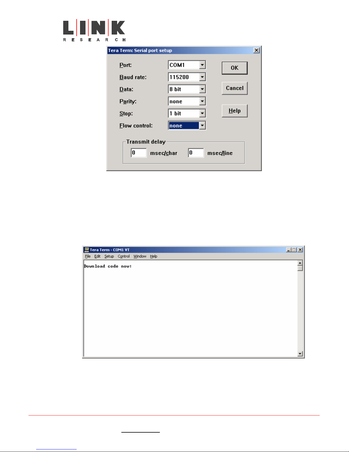
L2102 & L2104 Receiver
Instruction Manual
Figure 40 – configuring the COM port
Set the port up with the values shown in the screen dump and click ok.
The L1000 must be connected to the PC with a serial cable (minimum connections 2 – 2, 3 –
3 and 5 - 5) between the chosen COM port and LinkXP equipment data port. With the unit
un-powered, hold down the left and right arrow keys simultaneously on the front panel,
apply the power and continue to hold the keys down for a few seconds.
If the connection is successful, the following prompt will be seen on the PC screen.
Select the dropdown menu File then Send File on the terminal, and select the download
file, saved and unzipped on the local hard drive.
Link XP L2102/L2104 Receiver Instruction Manual Issue 1 - October 2003 Page 45 of 48
Link Research Ltd. 23/24 Watford Metro Centre, Dwight Road, Watford, Hertfordshire, WD18 9XA, England. Tel: +44 (0) 1923 200 900
Registered in London No. 2074604
Web: www.linkres.co.uk Fax: +44 (0) 1923 241 357
Figure 41 – Download ready
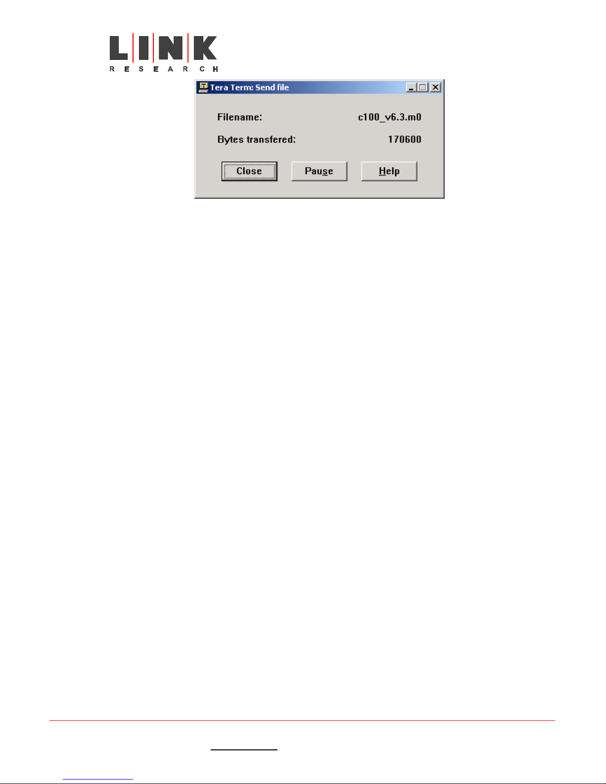
L2102 & L2104 Receiver
Instruction Manual
Figure 42 – downloading in progress
Once complete, the progress window will disappear, and a short time later (3-5 minutes),
the message ‘Finished’ will appear on the terminal screen. The updated code is now ready
to execute at next power up.
N.B. If the power is interrupted at any stage during this process, the new code will not
be loaded. In worst cases, the unit will have to be returned to the factory for a factory
reinstall.
Link XP L2102/L2104 Receiver Instruction Manual Issue 1 - October 2003 Page 46 of 48
Link Research Ltd. 23/24 Watford Metro Centre, Dwight Road, Watford, Hertfordshire, WD18 9XA, England. Tel: +44 (0) 1923 200 900
Registered in London No. 2074604
Web: www.linkres.co.uk Fax: +44 (0) 1923 241 357
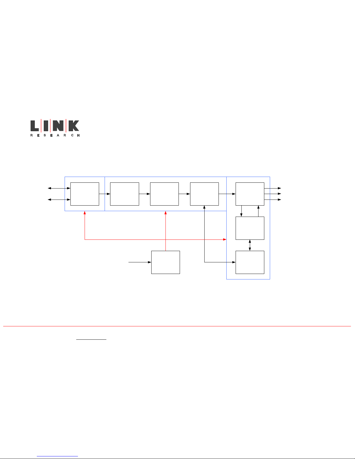
Link XP L2102/L2104 Receiver Instruction Manual Issue 1 - October 2003 Page 47 of 48
Link Research Ltd. 23/24 Watford Metro Centre, Dwight Road, Watford, Hertfordshire, WD18 9XA, England. Tel: +44 (0) 1923 200 900
Registered in London No. 2074604
Web: www.linkres.co.uk Fax: +44 (0) 1923 241 357
L2102 & L2104 Receiver
Instruction Manual
3.3 Block diagrams
3.3.1 L2102/L2104 Receiver block diagram
LNB power/RF
separation
Antenna 1
Antenna 2
Tuner Filter Demodulator
RF
RF
RF
Diversity decoder
Digital Signal
Processing
Front panel
interface
Transport
Stream
Analogue or Digtal audio out
C202 or C203 C201
C210
Analogue or Digital video out
Transport Stream out as ASI
Power Supply
Unit
AC mains in
NB L2104 has C202 and 2
off C201

Link XP L2102/L2104 Receiver Instruction Manual Issue 1 - October 2003 Page 48 of 48
Link Research Ltd. 23/24 Watford Metro Centre, Dwight Road, Watford, Hertfordshire, WD18 9XA, England. Tel: +44 (0) 1923 200 900
Registered in London No. 2074604
Web: www.linkres.co.uk Fax: +44 (0) 1923 241 357
L2102 & L2104 Receiver
Instruction Manual
3.3.2 L3010 Down convertor block diagram
Amp Amp
Amp
Amp
10dB
switched
attenuator
Mixer
10dB
switched
attenuator
10dB
switched
attenuator
DC block
control
data
separator
Switched
mode
power
supply
Program
mable
interface
controller
PIN
select
switch
Switch
inputs
for
attenuation
and Hi/Lo
oscillator
S-band
input
UHF band
output
1st LO
1.48GHz
2nd LO
1.84GHz
12VDC INPUT
 Loading...