

Page 1

LinkQuest Inc.
TrackLink 5000 USBL Tracking System
User’s Guide
Version 5000.6.2
This document is released to the designated organization under
non-disclosure agreement. Release of the electronic document
or its printout to any other party is prohibited.
Copyright 2005 by LinkQuest Inc. – All Rights Reserved
Page 2

1
to various countries.
Table of Contents
Table of Contents............................................................................................................1
1 Introduction.................................................................................................................2
2 Shipping Contents .......................................................................................................3
3 Installation ..................................................................................................................4
3.1 Transceiver and Transponder Installation .............................................................4
3.2 Tracking Software Installation ............................................................................7
4 Software Operating Instructions...................................................................................7
4.1 File .....................................................................................................................8
4.2 Run.....................................................................................................................8
4.3 View....................................................................................................................9
4.4 Configuration..................................................................................................... 10
4.5 Input.................................................................................................................. 10
4.6 Calibration.........................................................................................................11
4.7 Test ...................................................................................................................11
4.8 Transceiver ........................................................................................................ 13
4.9 Transponder....................................................................................................... 14
4.10 Simulation .......................................................................................................15
4.11 Help.................................................................................................................16
4.12 Acoustic Communication................................................................................. 16
4.13 Text Display ....................................................................................................17
4.14 Tracking Log ................................................................................................... 18
4.15 Data Output Format .........................................................................................18
5 Lab Test, Interfacing and Calibration.........................................................................20
5.1 Lab Test.............................................................................................................20
5.2 Interfacing .........................................................................................................21
5.3 Calibration.........................................................................................................21
5.4 Operation........................................................................................................... 24
6 Troubleshooting ........................................................................................................ 26
7 Customer Support......................................................................................................27
Appendix A: TrackLink 5000 System Specifications ....................................................28
Appendix B: TrackLink 5000 Series Intelligent High Power Transponders ....................29
Appendix C: Transceiver Cable and Connector Specification........................................32
Appendix D: Transponder Cable and Connector Specification...................................... 36
Appendix E: Error Messages ........................................................................................ 39
Appendix F: Transponder Battery Core Replacement....................................................43
Appendix G: Make Your Own ABP16D Battery Pack ..................................................53
Limited Warranty.......................................................................................................... 55
LINKQUEST END USER LICENSE AGREEMENT FOR FIRMWARE, SOFTWARE
AND DOCUMENTATION...........................................................................................57
The limited warranty is void if the product housing is opened for purpose other
than change of battery pack.
Export of LinkQuest products is subject to U.S. Export Administration
Regulations. Diversion contrary to U.S. law is prohibited. The ECCN of the
TrackLink 5000 systems is 6A001. Export licenses may be required for export
Version 5000.6.2
Page 3

2
1 Introduction
Thank you for purchasing LinkQuest’s TrackLink 5000 system, an USBL acoustic
tracking system with integrated high-speed acoustic communication capability. This
user’s guide applies to TrackLink 5000LC, TrackLink 5000MA and TrackLink
5000HA systems. Before operating the system you should read through the entire
user’s guide.
The TrackLink system tracks up to 8 targets up to 4000 meters of range using
TN5010 transponders and up to 5000 meters of range using TN5015 transponders
with ship noise level equivalent to the ambient noise level at (deepwater) Sea State 6.
The main differences among the 5000LC, 5000MA and 5000HA systems are the cost
and positioning accuracy. The specifications of the systems are provided in Appendix
A. The selection of the transponders is in Appendix B. Customized transponders are
also available upon request. Utilizing its benchmark Broadband Acoustic Spread
Spectrum (BASS) technologies, LinkQuest provides the end users with solutions for
underwater tracking and communication at sharply reduced cost and increased
accuracy and robustness.
The position of the submerged targets relative to the ship is determined by a
transceiver system and sent to a PC via a RS232/RS422 connection. The TrackLink
Navigator software integrates the transceiver with the ship's GPS/DGPS and a
compass. The targets’ relative bearings are adjusted to a true bearing using the
information from the compass. The actual position (latitude/longitude) of the target is
then calculated based on the range, true bearing and the surface support ship's
position as supplied by a GPS/DGPS receiver. The results are then graphically
displayed in the software. The positioning and related data may be stored and
retrieved for post processing.
The TrackLink system also has optional two-way acoustic communication capability.
It provides a flexible and reliable way for users to communicate with the target while
tracking it.
Main features of the TrackLink system are as follows:
• Extensive use of modern digital signal processing techniques and state-of-the
art DSP processors sharply reduced cost for end users.
• Broadband Acoustic Spread Spectrum (BASS) technologies.
• Strong rejection to multipaths and ship noise.
• Fully integrated with LinkQuest's most advanced high-speed acoustic modems.
The USBL transponder and acoustic modem share the same electronics and
transducer. It significantly reduces the total system size, weight and power
consumption and eliminates acoustic interference.
• Smaller and lighter transceivers allow easier and less costly installation from a
ship.
Version 5000.6.2
Page 4

3
• Advanced power-efficient DSP technology for the USBL intelligent
Warning
Warning
Warning
transponders results in extended field operating duration.
• PC Windows tracking software to display range, bearing, depth, GPS position,
acoustic communication data and other information from other sensors such as
an altimeter. Interfaces directly to the transceiver. No need for a heavy
proprietary deck unit.
2 Shipping Contents
The transit case typically contains one transceiver, one transponder, one 70 feet cable,
one 2-meter transponder cable and a CD for TrackLink Navigator software.
acoustic elements inside. Excessive force will either damage the acoustic
elements or affect the calibration which will result in less accuracy during usage.
The user should exercise caution during usage and transportation. The user
should dismount the transceiver after usage and place the transceiver inside the
transit case during transit. The user should avoid exposing the transceiver to
direct sunshine.
The transceiver is placed in a specially designed transit case. It is highly
recommended to use the transit case during transit. The protective transparent film is
used to further protect the surface of the hydrophone head. This film should not be
removed.
If the user wishes to place the transceiver in his/her own transit case, he/she needs to
place in the similar way. The case needs at least 2 inches of foam on top and bottom
of the transceiver. The user also needs to make a plastic film to protect the
hydrophone head.
an improper transit case.
The transceiver contains shock sensors. If more than 30g of force are applied on the
transceiver, the transceiver may be damaged.
force is applied to the transceiver during usage or transit.
: The transceiver is a delicate acoustic instrument. There are multiple
: The warranty is void if the transceiver is damaged from placement in
: The warranty is void if the shock sensor indicates more than 30g of
Version 5000.6.2
Page 5

4
3 Installation
Warning:
3.1 Transceiver and Transponder Installation
Transmitting in air at a high power level is prohibited for the
transceiver and transponder. Damage to the transducer may
result from it.
CAUTION
The TrackLink system is designed to track targets acoustically by interrogating the
target and to derive range and bearing information from the returned signal from a
target. The typical usages of the system are to track ROV, AUV, tow fish and diver.
3.1.1 Transceiver Introduction and Installation
The TrackLink transceiver consists of two components, i.e. a hydrophone array and
an acoustic transmitter. The acoustic transmitter is connected to the hydrophone array
through a short cable and is detachable. The user does not need to install the acoustic
transmitter when tracking the target using Electrical Trigger mode, i.e. tracking a
responder.
The user should install the transceiver to a rigid fixture on a ship. Typical installation
is from a steel/iron pole or a gate valve. The user should face the transducer (the
black end of the transceiver) to the seabed and submerge the transceiver in the water.
The user can also tilt the transceiver towards the target for tracking purpose. See the
installation drawing for more details. The user should align the X/Y axis in the
installation drawing with the X/Y axis in the TrackLink Navigator software.
The detachable acoustic transmitter is typically installed at the same level and close to
the hydrophone array. However, it can be also installed certain distance away from
the hydrophone array if necessary.
vibration will either damage the acoustic elements or affect the calibration which
will result in less accuracy during usage. The user should exercise caution during
installation and usage to avoid excessive shock and vibration. The user should
dismount the transceiver after usage and place the transceiver inside the transit
case during transit.
The transceiver is a delicate acoustic instrument. Excessive shock and
Version 5000.6.2
Page 6

5
Warning
if the shock sensor indicates more than 30g of force is applied to the transceiver
during usage or transit.
: Shock sensors is installed inside the transceiver. The warranty is void
To achieve optimal performance, the user should install the transceiver 1 meter (3
feet) below the ship’s hull when installed from a pole and flush when installed from a
gate valve.
The accuracy of the absolute position depends on the accuracy of the true bearing,
GPS/GPS and pitch and roll compensation. The user should choose the proper
instruments and operate them correctly. Both sound speed and the bending of acoustic
signal in water will impact position accuracy. A thorough study of the temperature
and salinity in the area of operation will help to improve the accuracy.
Static Heading Offset and pitch/roll offset caused by installation also directly impact
position accuracy. The user is advised to review the section on Calibration to properly
compensate for these offsets.
The TrackLink transceiver is connected to a PC on the ship through a cable. The PC
software communicates with the transceiver using an RS232 serial link. Before using
the transceiver, the user should check the capability and the sufficiency of the power
supply for operation.
Please refer to LinkQuest’s installation drawings for installation. The X, Y directions
are represented by the X, Y of the TrackLink Navigator software.
Warning: The user should minimize the shock to the transceiver system installed
from the ship. The shock limits for the transceiver system is defined in the
Specification A. When the ship is moving at high speeds, the user should remove the
transceiver from the steel pole so that the vibration caused by the ship’s high speeds
will not damage the transceiver.
3.1.2 Transponder Introduction and Installation
The transponder is either powered externally or internally. Before using the
transponder, the user should check to be sure that the power supply has sufficient
reserves to operate the transponder for the desired service time (refer to Appendix B).
The transponder can be configured to the “Transponder”, the “Responder” or the
“Pinger” mode. In the “Transponder” mode, the transponder is in the standby mode
while it is not in active operation. It will revert to “Wake Up” mode when
commanded by the TrackLink Navigator software. The transponder will then stay in
Version 5000.6.2
Page 7
6
the active responding mode one hour from the last time a valid acoustic interrogation
from the transceiver is received.
The transponder can also be configured to the “Responder” mode. In this mode, the
transponder will be triggered by the electrical signal. Details can be found in
Appendix D.
The transponder can be configured to the “Pinger” mode to output acoustic signals
every second. This mode is mainly used for testing purposes.
Important: The transponder with internal batteries (Model C) is typically
shipped with a power-on plug. The transponder is in complete power off state
when the plug is not plugged. Therefore this power-on plug should not be
plugged into the transponder during storage. The power-on plug needs to be
plugged into the transponder during normal operation.
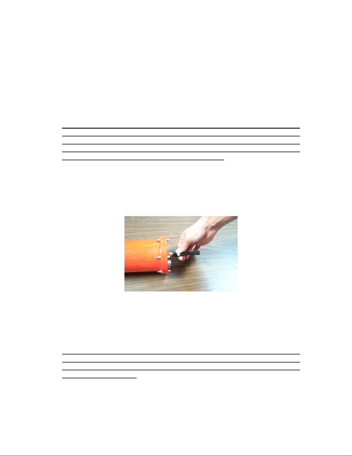
Warning: The user should plug and unplug the power-on plug by holding firmly
on the top (hard) part of the plug as shown in Figure 1. Squeezing or pulling on
the tail of the plug may cause breaking of the wire connections inside the plug.
The damage caused may result in non-functioning of the transponder.
Figure 1
The user should install the transceiver and transponder properly so that the tracked
target will be within the operational beamwidth of the transceiver and the
transponder.
Warning: The limited warranty is void if the housing of the transceiver is
opened. The limited warranty is also void if the transponder housing is opened
for any purpose other than changing of batteries or the electronics of the
transponder is tampered.
The product should only be used under non-corrosive environment. Non-corrosive
environment may include both fresh and salt water. The product housing must be
protected against abrasion that may damage the housing’s protective coatings. This
Version 5000.6.2
Page 8

7
product is equipped with corrosion preventive mechanism (i.e. zinc anode). If the
Caution
product housing were to be electrically connected to other underwater instruments,
the connection must be made such that the effect of the anti-corrosive mechanism is
not diminished.
: The user should make sure that the transducer on the transponder will
not take any direct hit, scratch or drag. The user is advised to use a guard to
protect the transducer. A guard can be typically made of thin steel rails. The
diameter of the rail is recommended to be less than 5 mm. The rail should be at
least 1.5 cm away from the transducer.
3.2 Tracking Software Installation
The TrackLink Navigator software displays the positions of the ship and the targets in
various plots and textual displays.
IMPORTANT: If there is any TrackLink program installed on this computer,
including demo and previous versions, please uninstall it first and delete the
C:\tracklink directory.
IMPORTANT: Please go to “Control Panel” -> “Regional Settings” to make
sure “English (United States)” is selected. It is required for the software to work
properly.
Insert the software CD into CD-ROM drive. Run the setup.exe program to install the
TrackLink Navigation software.
Run the software from Start->Program->tracklink. The user may also create a
shortcut for the program on the desktop.
The user needs to enter the serial number twice the first time running the software.
Please make sure to enter the correct number.
4 Software Operating Instructions
This section describes the functions provided by the menu bar of the TrackLink
Navigation software. The user should first read through this section before proceeding
to the next section on interfacing and calibration.
Warning: The TrackLink Navigator software relies on the serial communication to
interface with the transceiver, GPS, compass, motion sensor/VRU and other devices.
In order to minimize the impact of buffer overflow and delayed responses to serial
communication, the user is advised to exit all nonessential applications running on the
same computer.
Version 5000.6.2
Page 9

8
IMPORTANT: The user needs to make sure the serial ports work reliably with
the external devices such as GPS, compass and motion sensor. The user is
advised to test the serial ports’ connections to the external devices using
HyperTermial first. In particular when a USB/RS232 converter is used to
provide serial port support, the use needs to test the reliability of this serial port.
There are occasions computer crashes when such a serial port is used to
interface to GPS, compass or motions sensor. When it happens, the user is
advised to use the original serial ports of the computer to connect to the external
devices.
IMPORTANT: If the RS232 communication between the computer and the
transceiver is impacted by electrical noise, the user should improve the
grounding conditions of the computer. The user may connect the metal shields of
the transceiver cable to the ground of the computer. For notebook computers,
the ground is the screw hole for the DB9 connector. The user may further
improve the ground condition by connecting the computer ground to water. On
a metal ship, connecting to the ship deck is equivalent to connecting to water.
4.1 File
Load
This loads the history of ship and target positions. The software uses the history of
positions as the starting points of the plot.
Save As
Saves the current positions, including the loaded history positions, to a file.
Save Bitmap
Saves the entire software display to a bitmap file.
Print
Prints the whole software display.
Exit
Exits the TrackLink Navigator software.
4.2 Run
Reset
Resets the transceiver.
Version 5000.6.2
Page 10

9
Start
Starts both target(s) and ship tracking.
Clear
Clears all the positions in the plots. The historical positions will not be cleared.
They can be saved to a user-selected file after the tracking is stopped.
Stop
Stops both target and ship tracking.
Wake Up
Wakes up a transponder with the selected address. It lasts for about 20 seconds for a
selected target. This command can also wake up all targets at once by selecting
“All” in the address pull down menu. There is no need to run this command if the
transponder is configured to the “Responder” mode.
Warning: The user should avoid running the wake up command continuously
for more than 2 minutes.
4.3 View
Choose the “Bow Reference” view or the “North Reference” view. In the “Bow
Reference” view, the plot will show the target’s relative positions to the ship
(transceiver). The heading of the ship is displayed at the up right hand corner of the
plot when a compass interface is available.
In “North Reference” view, the plot will show the target’s absolute positions in
longitude and latitude. The ship’s bow rotates with reference to the direction
“North”.
The most recent 300 positions are used for the trajectory of the targets.
“Scale Down” scales down the main tracking plotting. This command is enabled
only when the tracking is active.
“Scale Up” changes the TrackLink Navigator window to full screen. This command
is only available when the screen is in “Scale Down” status. Please note the
Maximum button on the up right corner of the window does not work at this time.
Version 5000.6.2
Page 11

10
4.4 Configuration
Serial Ports
Configures the serial interface to the transceiver/transponder (This interface is
usually connected to transceiver. If the user wants to configure a transponder he
needs to unplug the transceiver cable and plug in the transponder cable.), GPS,
compass, and external VRU if available. The user can also select a serial port to
output the target positions and select a serial port for acoustic communication data.
The user is advised to test all the interfaced devices before target tracking is started.
See section 4.7 (Test) for more details.
Interrogation Rate
Configures how fast the target is interrogated. The minimum value is about 1.5
second depending on the tracking distance. The maximum value is 60 seconds.
Unit
Configures the unit (meter, foot or yard) used in plot and textual display.
Targets
Input the valid target addresses and names. The user could also choose the plotting
target symbol on this window.
Warning: The user should avoid inputting addresses for a non-existing target. The
software will time out on such non-existing target and cause delays in interrogating
other valid targets. The user should make sure there is at least one valid target
address is selected before clicking the “Start” button.
4.5 Input
Sound Speed
Inputs the sound speed near the TrackLink transceiver. The default value is 1500
meters/second. The value of sound speed will impact the accuracy of the range and
bearing output.
For the TrackLink 5000LC system, the sound speed input is ignored due to this
system’s relatively low accuracy.
Version 5000.6.2
Page 12

11
4.6 Calibration
Load
Loads the calibration result generated by LinkQuest’s automatic calibration
software, TrackLink Calibrator. It will only be enabled when the user purchased the
TrackLink Calibrator software.
Heading Offset
Inputs the heading offset caused by the installation. Please refer to section 5.3.1 and
5.3.2.
Pitch/Roll offset
Inputs the pitch/roll offsets caused by the installation. Please refer to section 5.3.3
Pitch and Roll Offset.
GPS Offset
Inputs the GPS offsets from the GPS antenna to the transceiver. The calibration
procedures are discussed in section 5.3.4.
4.7 Test
Test Transceiver
When “Interrogate the Target” is selected, this function tests the serial
communication with the transceiver, tracks the target once and determines whether
the transceiver is functioning well in tracking. It returns error code when no target is
available.
When “Interrogate the Target” is not selected, this function tests if the serial
communication with the transceiver is good and if the rs232 line is clean and checks
whether the transceiver is powered on properly.
Test GPS
Tests the GPS outputs for proper position data and frequency. The frequency of the
data output is required to be no less than 2 Hz (twice every second).
The TrackLink Navigator assumes the GPS outputs NMEA data strings “GPGGA”
or “GPGLL”.
Version 5000.6.2
Page 13

12
Warning: When GPS input is selected in “Serial Ports” setting, no valid position
will be generated if no valid GPS information is available. In other words, the
targets cannot be tracked in this case.
Test Compass
Tests the compass outputs for proper heading data and frequency. The frequency of
the data output is required to be no less than 2 Hz (twice every second)
The TrackLink Navigator assumes the compass outputs NMEA data strings
“HCHDM”, “HCHPR”, “HCHDT” or “HEHDT”.
Warning: When compass input is selected in “Serial Ports” setting, no valid position
will be generated if no valid compass information is available. In other words, the
targets cannot be tracked in this case.
Test VRU
Tests the VRU/motion sensor outputs. Currently the TSS format is supported. The
format is as follows
:00ffeb 0004 -0505 –0316
Where the 3rd and 4th numbers are roll and pitch in 1/100 degree respectively.
Warning: When VRU/motion sensor input is selected in “Serial Ports” setting, no
valid position will be generated if no valid VRU information is available. In other
words, the targets cannot be tracked in this case
Noise
Measures the noise level at the transceiver. The user needs to power off and then
power on the transceiver before running the noise test.
Debug 1
Configures the system to be in “Debug 1” mode. Tracking when “Debug 1” is
activated will cause the system to record detailed debug information. Contact
LinkQuest for details when the “Debug 1” feature is used to resolve problems in
field deployment.
Debug 2
Configures the system to be in “Debug 2” mode and run the “Debug 2” test. It takes
about five minutes to complete. Contact LinkQuest for details when the “Debug 2”
feature is used to resolve problems in field deployment.
Version 5000.6.2
Page 14

13
Debug 3
Configures the system to be in “Debug 3” mode and run the “Debug 3” test. It takes
about 8 minutes to complete. Contact LinkQuest for details when the “Debug 3”
feature is used to resolve problems in field deployment.
Debug 4
Configures the system to be in “Debug 4” mode and run the “Debug 4” test. It takes
about 10 minutes to complete. Contact LinkQuest for details when the “Debug 4”
feature is used to resolve problems in field deployment.
4.8 Transceiver
Test
When “Interrogate the Target” is selected, this function tests the serial
communication with the transceiver, tracks the target once and determines whether
the transceiver is functioning well in tracking. It returns error code when no target is
available.
When “Interrogate the Target” is not selected, this function tests if the serial
communication with the transceiver is good and if the rs232 line is clean and checks
whether the transceiver is powered on properly.
Mode
Clicking on “Get” gets the transceiver’s operation mode. “Set” sets the selected
mode for the transceiver. When the “Acoustic Interrogation” mode is selected, the
transceiver interrogates all transponders acoustically. Therefore all transponders
need to be set at “Transponder” mode. When the “Electrical Trigger” mode is
selected, the transceiver interrogates the transponder with address 1 electrically
while still interrogating transponders with all other addresses acoustically. In this
case, the transponder with address 1 needs to be set at the “Responder” mode while
all other transponders stay at the “Transponder” mode.
Power
Clicking on “Get” gets the transceiver’s operation power level. “Set” sets the
selected power level for the transceiver.
Threshold
Clicking on “Get” gets the transceiver’s operation threshold. “Set” sets the selected
threshold for the transceiver. This parameter determines the signal level that will be
Version 5000.6.2
Page 15

14
obtained by the system. Changing it will alter the system performance significantly.
Please use caution to do so.
Version
Gets the firmware version of the transceiver.
Configuration Reset
Restore the original configuration of the transceiver. Please use caution when apply
this command.
Note: Please always apply the “Get” function after sets a value to verify if the “Set”
is successful.
Diagnostic Info
This function helps the user troubleshoot when the system is not working properly.
Contact LinkQuest for details
4.9 Transponder
These functions are only valid for standard TrackLink transponders that support
RS232 serial communication. The user should use the same serial port number used
by the transceiver as configured in “Serial Ports” setting.
Test
Tests the serial communication with the transponder and determines whether the
transponder is functioning.
Address
Retrieves and sets the addresses of the transponders. The address is from 1 to 8.
Only address 1 could work in the electrical trigger mode.
Mode
Gets transponder mode and changes the transponder mode for testing purpose.
Clicking on “Get” gets the transponder mode. The transponder should be in the
“Transponder” mode for the TrackLink system to function properly using acoustic
interrogation. The “Responder” mode requires the transceiver to be configured to the
“Electrical Trigger” mode.
Version 5000.6.2
Page 16

15
When the transponder mode is set to the “Pinger” mode, the transponder will send
out acoustic every second. This feature may be useful for troubleshooting the overall
system.
Power
Clicking on “Get” gets the transponder’s operation power level. “Set” sets the
selected power level for the transponder.
Threshold
Clicking on “Get” gets the transponder’s operation threshold. “Set” sets the selected
threshold for the transponder. This parameter determines the signal level that will be
detected by the system. Changing it will alter the system performance significantly.
Please use caution to do so.
The user is highly recommended to use the default threshold value.
Version
Gets the firmware version of the transponder.
Wakeup Period
Gets and sets transponder wakeup period. Setting the wake up period to 0 will make
the transponder wake up all the time. Therefore there will be no need to perform
“Run->Wake Up” function for this transponder before the tracking starts.
Warning: Setting the wake up period to 0 will consume significantly more power.
Configuration Reset
Restores the original configuration of the transponder.
Diagnostic Info
This function helps the user troubleshoot when the system is not working properly.
Contact LinkQuest for details.
4.10 Simulation
This function simulates the tracking output and display as if active tracking is in
progress. In the case the user purchased a particular serial data output driver, this
function will generate the serial output data and send the data to the serial port
Version 5000.6.2
Page 17

16
configured in Configuration->Serial Ports. The user can use this output to test the
serial link interface to other software or instrument.
Run
Runs the tracking simulation.
Clear
Clears all the positions in the plots.
Stop
Stops the tracking simulation.
4.11 Help
Restore Database
This function is used to recover from errors caused by configuration information loss.
If the user encounters some error message (for example error messages 13-18), and
after restarting the program and rebooting the computer, the TrackLink Navigator
software still does not work properly, this function can help the user to restore the
database using the default configuration. After issuing “Restore Database”, the user
needs to close the TrackLink software and run it again. The user needs to reconfigure
the system’s serial ports and targets after Restore Database.
Software Version
The user gets the version of the TrackLink Navigator software.
Error Message
Shows the error message description.
4.12 Acoustic Communication
TrackLink system has optional integrated acoustic modem function to transfer 20 or
80 bytes data in each interrogation between the transceiver and transponder address 1.
Higher data rate acoustic modem function is also available.
When the USBL transceiver interrogates the transponder. The user data will be
piggybacked following the USBL interrogation signal. When the USBL transponder
receives the interrogation, it will send a response and piggyback any acoustic modem
data following it. By doing so, acoustic interference is avoided.
Version 5000.6.2
Page 18

17
The user needs to configure a serial port for the acoustic communication. Please refer
to section 4.4 Configuration. This port connects to a user's computer or device, which
sends downlink data. The TrackLink software sends the data to the transceiver and
the transceiver in turn sends it to the transponder address 1 when interrogating the
transponder. The underwater device on the target sends uplink data to the
transponder through a serial port. After the data are received at the transceiver, the
data will be sent from the TrackLink Navigator software to user's computer through
the designated serial port.
Note: The user should use a Null Modem converter between the TrackLink
Navigator computer and the user's computer for input and output of acoustic
modem data.
IMPORTANT: External power supply for transponder needs to be used for
acoustic modem function due to the higher current requirement for continuous
transmission. The peak current requirement for acoustic communication is 1.2 A
at 27 volts.
For Type 8 (T8) acoustic communication, an integrated high speed UWM4010
acoustic modem is implemented for the uplink acoustic communication from the
transponder to the transceiver. Refer to the user’s guide for UM4010 modem for
interfacing issues. Please note the uplink data will be sent to a separate cable at the
transceiver.
The acoustic communication relies on the success of the USBL interrogation. If the
interrogation fails, the data will be lost.
4.13 Text Display
The positioning information is shown in textual format at the right hand corner of the
software display. It shows the name of the target, the time of the interrogation, the
longitude, latitude and heading of the ship. It also shows the X and Y positions of the
target in the “Bow Reference” view, the longitude and latitude of the target, the
(horizontal) range and slant range from the transceiver to the target, the bearing of the
target relative to the ship (transceiver) and the depth of the target.
The unit (meter, foot or yard) used by X, Y, range, slant range and depth is shown at
the left hand corner of the “Bow Reference” view plot.
The depth is a calculated value when depth sensor and acoustic communication
options are not available. This value is less accurate at wider beamwidth. When no
valid value can be calculated, an ‘*” symbol is shown.
For all invalid or unavailable values, “*” symbols instead of numeric values will be
shown.
Version 5000.6.2
Page 19

18
The time-depth plot shows the target depth information for the past 100
interrogations. The depth information is calculated and may only be accurate within
limited beam width.
The Acoustic Communication window displays up to 80 characters. The window will
be updating when the next interrogation happens. A label above the window shows
the communication direction, namely Downlink and Uplink. Downlink means the
communication from the surface ship to the target. Uplink means the communication
from the target to the surface ship.
The user should also pay close attention to the textual messages at the bottom right of
the TrackLink Navigator software display for certain warning and error messages.
The most right cell shows the error code. Only “0” means tracking is successful.
4.14 Tracking Log
The hp326.txt file saves the tracking history.
hp326.txt is in the working directory: C:\tracklink. The new data are appended to the
end of the previous data. When the file size reaches 1.5Mbytes, it is copied to
C:\tracklink\hist directory and renamed as hist +"current date and time".txt. Then the
new data is saved to a newly created hp326.txt file.
Following is the format of the data string:
target_address error_code year month day hour minute second range bearing X Y
Depth option_code shipLat shipLon option_code heading option_code TargetLat
TargetLon SlangRange reserve option_code pitch roll reserve reserve reserve reserve
reserve
If error code is not zero, ignore the position.
X, Y, Depth and Range are in meters. The SlantRange is in cm. Bearing, heading and
pitch/roll are in degrees.
The user should check the files in the C:\tracklink\hist directory from time to time and
remove old files if necessary.
4.15 Data Output Format
TrackLink software has three data output formats, namely TP2 compatible, GLL, and
LXT compatible. The user may purchase one or more data output formats. Following
are descriptions of these formats:
TP2 compatible output format:
Version 5000.6.2
Page 20

19
1 11:08:51 0 229.4 199.7 -10.8 -9.3 199.2 0.0
Target number - Character 1
Time - Character 3-10
Reserved - Character 12-14
Target Bearing - Character 16-20
Slant Range - Character 22-28
X Offset - Character 30-37
Y Offset - Character 39-46
Z Offset - Character 48-54
Reserved - 56-63
Reserved - Character 65-66 (blank)
CR - 67
LF – 68
GLL output format:
$GPGLL,4916.45,N,12311.12,W,225444,A
4916.46,N Latitude 49 deg. 16.45 min. North
12311.12,W Longitude 123 deg. 11.12 min. West
225444 Fix taken at 22:54:44 UTC
A Data valid
A followed by “CR” and “LF”
LXT compatible output format:
1 9999.9 359.9 89.9 359.9 9999.9 899.9 55
Target number
Slant range
Bearing
Depression angle
Reserved
Reserved
Reserved
Reserved
It is a fixed 41-character length not including CR, LF. This format is ended with
“CR” and “LF”.
Spaces are inserted for reserved fields.
Version 5000.6.2
Page 21
20
5 Lab Test, Interfacing and Calibration
5.1 Lab Test
The user is recommended to perform a lab test of the system before operating the
tracking system from the ship.
Place the transponder and transceiver into a small water tank or barrel, which can at
least hold the transducer (black rubber part) of the transponder and the bottom (black
urethane) part of the transceiver. It is recommended the size of the water tank or
barrel is no less than 50 gallons.
IMPORTANT: The distance between the top of the transponder and the bottom
of the transceiver is recommended to be around 1 inch. The user should try to
place the transponder and transceiver at center of the water tank, as far away
from the tank walls, bottom and water surface as possible.
Connect the transceiver to the computer and power on it with the transceiver cable.
Power on the transponder using external power or the power-on plug if the
transponder has internal battery. By using the TrackLink Navigator interface:
• Setup the target address. See 4.4 Configuration
• Configure the transceiver serial port. See 4.4 Configuration
• Wake up the transponder. See 4.2 Run.
• Test the transceiver. See 4.8 Transceiver.
• Run the tracking software. The software will display the target positions in
the plots and show the textual positioning information.
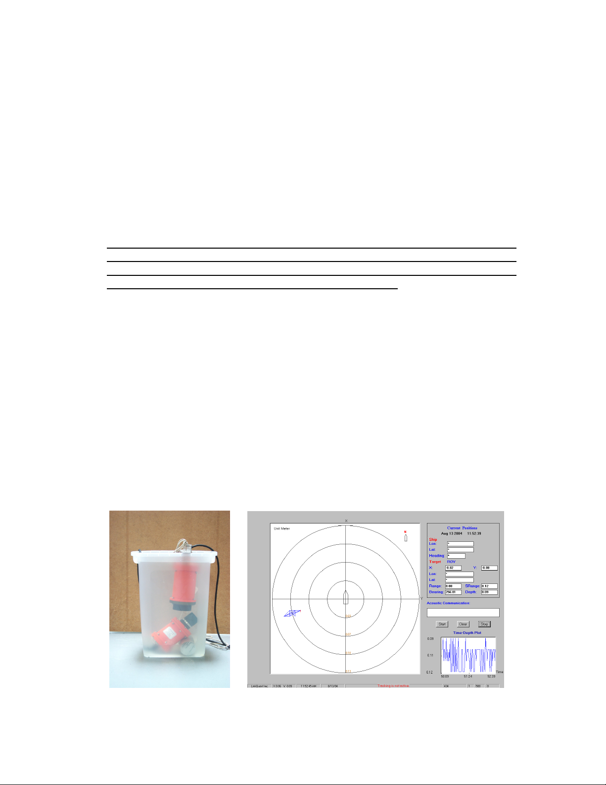
Followings are the illustrations of TrackLink systems in testing in a small office
waste can. The user is recommended to use a larger water tank or barrel for easier
setup of the lab test.
Version 5000.6.2
Page 22

21
Note: The pictures are for illustration purpose. The exact color and size of the system
may vary.
Note: Occasional jumping of target positions on the display is possible due to the
severe multipath conditions inside a small water tank. The user should adjust the
positions of the transceiver and transponder to find the optimal setup for the test.
5.2 Interfacing
The TrackLink Navigator software interfaces to a transceiver, a GPS, a compass and
a VRU through serial ports. It may also send out positioning data to a serial port. And
send or receive acoustic communication data. Depending on the options (drivers) the
user purchased from LinkQuest, up to 6 serial ports may be required.
If the user does not have existing multi-serial ports, an USB-serial port converter may
be used to convert the USB port to support multiple serial ports.
If the user does not have existing multi-serial ports, an USB-serial port converter may
be used to convert the USB port to support multiple serial ports.
IMPORTANT: when a USB/RS232 converter is used to provide serial port
support, the use needs to test the reliability of this serial port. There are
occasions computer crashes when such a serial port is used to interface to GPS,
compass or motions sensor. When the problem occurs, the user is advised to use
the original serial port of the computer (typically COM1) to interface to the
external devices.
The interface to GPS and compass are optional. Without interfacing to GPS and
compass, only the target’s relative position to the ship (The Bow Referenced view) is
displayed. The North Reference view is disabled.
After the user connects to the transceiver and other external devices through the serial
ports, the user needs to go to “Configuration” on the menu bar and select “Serial
Ports”. In the pop-up window, enable an interface to a device by checking the box left
of the device name before selecting the COM port and the baud rate corresponding
for this particular device. If a device is not interfaced, the user needs to disable the
device by un-checking the box left of the device.
After the configuration is completed, the user needs to go to “Test” on the menu bar
and test each device before proceeding with normal tracking operations.
5.3 Calibration
The user can follow the simple procedures below to calibrate the TrackLink 5000
system. For users who purchased the TrackLink Calibrator software, he/she can load
Version 5000.6.2
Page 23
22
the result generated by the automatic calibration software by selecting the
Transponder
Transceiver
Same
Calibration->Load Calibration function.
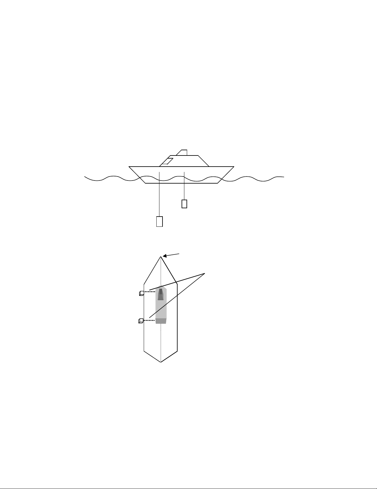
5.3.1 Heading Offset
Heading Offset is caused by the installation of the transceiver when it is not aligned
with the bow of the vessel (see Figures 2a & 2b). The offset is used to adjust the
target’s bearing information (relative to the transceiver) to the target’s actual heading
based on the knowledge of the ship’s heading information.
Transponder
Transceiver
5.3.2 Determination of a Heading Offset
With the TrackLink transceiver on, place a transponder directly in line with the
transceiver off the bow of the vessel. Track the transponder with the TrackLink
Navigator software. Note the relative bearing displayed on the software. This value
Figure 2a
Bow of ship
distance
Top view of ship
Figure 2b
Version 5000.6.2
Page 24
23
should be centered about 0 degrees (i.e. between 358 to 2 degrees). Repeat the
Transceiver
Transceiver
procedure until the relative bearing is within acceptable limits. If an offset exists
substantially beyond these limits then enter a correction by selecting Calibration ->
Heading Offset.
5.3.3 Pitch and Roll Offset
Place a pitch and roll sensor, a VRU or a motion sensor on the fixture (e.g. a steel
pole) where the transceiver is installed. Make sure the sensor is leveled with the endcap of the transceiver and +pitch points to the +X direction of the transceiver. Record
the pitch and roll information from the sensor. Average the values if necessary. Enter
the offset by selecting Calibration -> Pitch/Roll Offset.
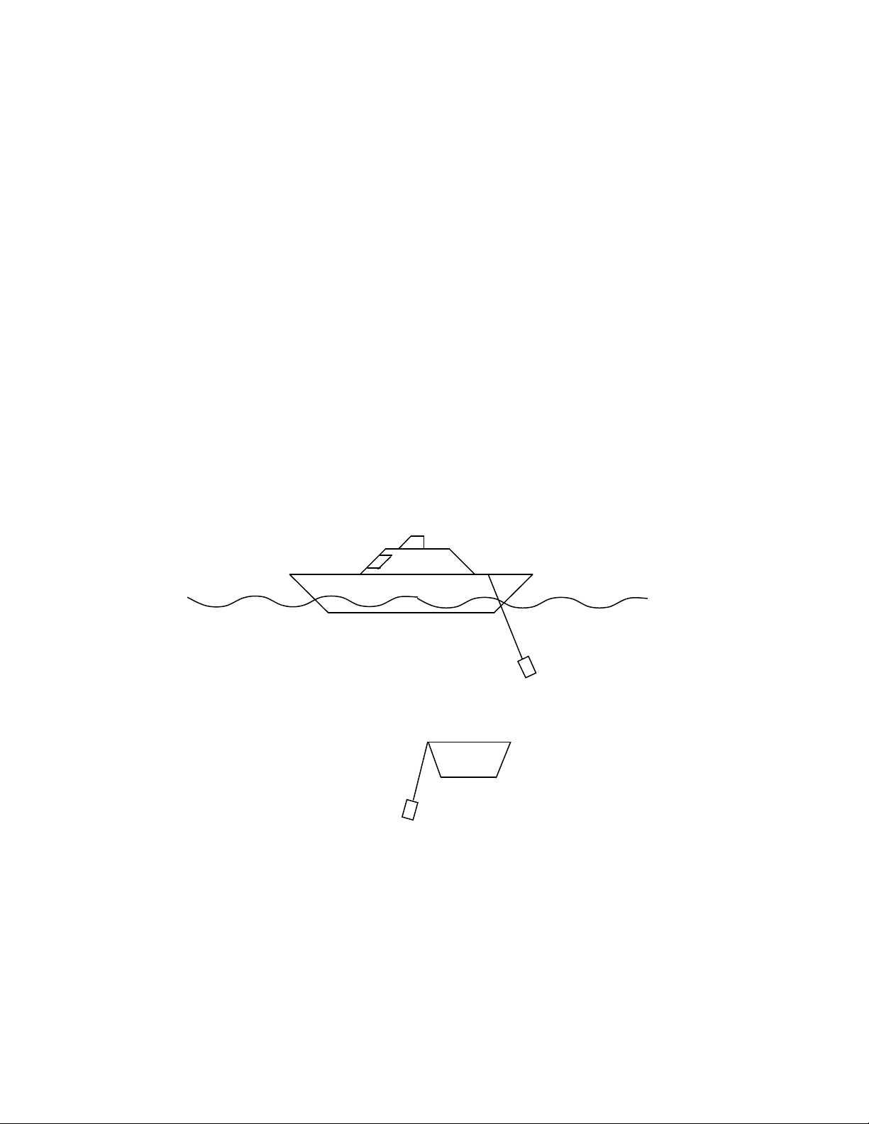
If the transceiver is tilted to the stern direction, the pitch offset value is negative.
Refer to Figure 3.
The user should also input the pitch offset if the transceiver is tilted to the stern
intentionally to track a target, e.g. a towfish, behind the ship’s stern.
If the transceiver is tilted to the port direction, the roll offset value is positive. Refer
to Figure 4.
Figure 3
Ship Stern View
Figure 4
5.3.4 GPS Offset
The TrackLink Navigator software uses the positioning information from the GPS
installed on the ship. When the GPS antenna is located far away from the transceiver,
Version 5000.6.2
Page 25
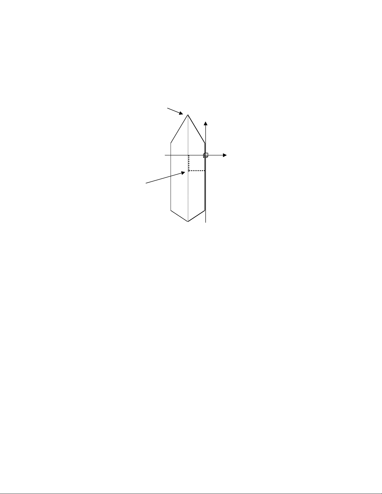
24
the offset from the transceiver to the GPS antenna needs to be compensated for. Enter
Y
.
X
GPS
the offset by selecting Calibration -> GPS Offset.
For example in Figure 5, the GPS X Offset is -5 meters while the GPS Y offset is -4
meters.
Bow of ship
Antenna
4m
5m
Figure 5
Transceiver
Top view of ship
5.4 Operation
After the interfacing and calibration are completed, the user is ready to track targets
with the TrackLink system.
LinkQuest’s TrackLink transceiver uses a widebeam hydrophone array. It has the
benefits of a directional receiver to better reject the ship’s engine noise and other
surface noise while gaining more flexibility in tracking targets as compared to a
narrow-beam hydrophone array.
LinkQuest’s TrackLink 5000 system (hydrophone array) is optimized to track targets
within 120 degrees of beamwidth (+/- 60 degrees). If a target is between 120 to 140
degrees of beamwidth, it may be tracked with decreased accuracy and robustness.
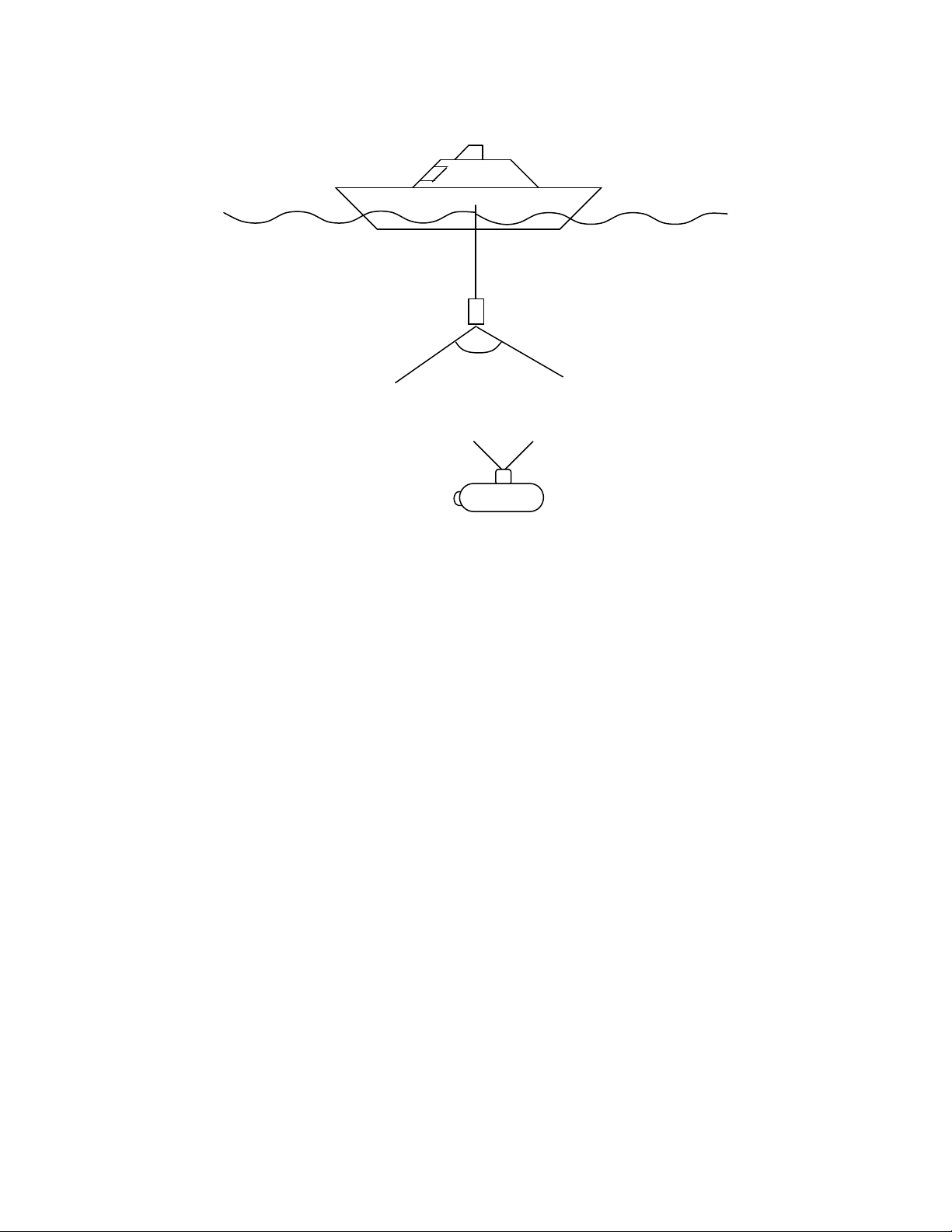
Although targets may be tracked beyond 120 degrees of beamwidth, it is highly
recommended that the user DOES NOT plan to track targets beyond the 120-degree
beamwidth (see Figure 6). If the transponder’s beamwidth is smaller than
transceiver’s beamwidth or the acoustic transmitter of the transceiver is used, the
effective beamwidth of the whole system is determined by the transponder’s
beamwidth or the acoustic transmitter’s beamwidth (70 to 90 degrees), whichever is
smaller.
Version 5000.6.2
Page 26
25
Transceiver
120
o
Target with
Transponder
Figure 6
After powering on the systems, the user is advised to test all the devices such as the
transceiver, GPS, and compass connected to the PC using the “Test” features on the
TrackLink Navigator software menu bar. If all the tests passed, the user can start to
track the targets.
The user should pay attention to the message box at the bottom of the Window. If a
warning message appears instead of “Tracking is active …” message, the user should
address this issue immediately. The software may display one or more of the
following warning messages:
• "WARNING: Can't Communicate with Transceiver." The software cannot
communicate with the transceiver. In this case, the serial link may be broken
or the transceiver may be malfunctioned or powered off.
• “WARNING: No Valid GPS Data.” The software has not received valid data
from the GPS. In this case, the GPS may be malfunctioned or the serial link
between the PC and the GPS is broken. It is also possible that the GPS output
of the valid data is not frequent enough. It is required that the output
frequency be no less than 2 Hz.
• “WARNING: No Valid Compass Data.” The software has not received valid
heading data from the compass. In this case, the compass may have
Version 5000.6.2
Page 27

26
malfunctioned or the serial link between the PC and the compass is broken. It
is also possible that the compass has not provided data frequently enough. It is
required that the output frequency be no less than 2 Hz.
• “WARNING: No Valid VRU Data.” The software has not received valid pitch
and roll data from the compass. In this case, the VRU may have
malfunctioned or the serial link between the PC and the VRU is broken. It is
also possible that the VRU has not provided data frequently enough. It is
required that the output frequency be no less than 2 Hz. For better
compensation of the pitch and roll of the ship, the output frequency is
recommended to be higher than 30 Hz.
• “WARNING: No Valid Transceiver Data” The transceiver may have
malfunctioned or lost the synchronization with the TrackLink Software.
Power off the transceiver and try again.
• “WARNING: RS232 Link to Transceiver is NOT Clean!” The serial link
between the transceiver and the computer is not clean. This is a very serious
problem. It is usually caused by improper installation. The user may check the
grounding of the computer and etc. This issue must be addressed before
performing the tracking.
If the user selects a particular device in “Serial Ports”, the tracking software will not
be able to display a position if the selected device cannot output the required valid
data.
Warning: The user should minimize the shock to the transceiver system installed
from the ship. The shock limits for the transceiver system is defined in the
Specification. When the ship moves at high speeds, the user should remove the
transceiver from the steel pool so that the vibration caused by high-speed motion
does not damage the transceiver.
6 Troubleshooting
The TrackLink Navigator software returns intuitive error messages and error codes
when an error is detected. The details can be found in Appendix E.
The “Debug 1”, “Debug 2”, “Debug3” and “Debug4” features under “Test” on the
menu bar provide various ways for the user to collect more detailed debug
information. The user is advised to inquire more information from LinkQuest if
further details are needed.
Version 5000.6.2
Page 28

27
7 Customer Support
If technical problems with the instruments cannot be resolved using the procedures
instructed in the troubleshooting section, the user should contact his/her local
representative or contact LinkQuest directly in any of the following ways:
• Telephone: (858) 623-9900, 623-9916, 623-9919
• Fax: (858) 623-9918
• Email: [email protected]
• Internet: http://www.link-quest.com
• Mail to: LinkQuest Inc.
6749 Top Gun Street, Suite 100
San Diego, CA 92121
U.S.A.
Version 5000.6.2
Page 29

28
Appendix A: TrackLink 5000 System Specifications
Positioning Accuracy:
TrackLink 5000LC: 3.0 degrees
TrackLink 5000MA: 1 degree
TrackLink 5000HA: 0.25 degree
Slant Range Accuracy: 0.30 meter
Targets Tracked: 8
Operating Frequency: 14.2 kHz – 19.8 kHz without acoustic modem option
12.75 kHz – 21.25 kHz with acoustic modem option
Transceiver operating Beamwidth: 120 degrees (hydrophone array)
70 to 90 degrees (acoustic transmitter)
Working range with ship noise: up to 5000 m with TN5015 transponders
up to 4000 m with TN5010 transponders
Maximum transceiver depth: up to 20 m
Input voltage: 46 to 48 Volts DC
Transmit mode power consumption: 40 Watts
Receive mode power consumption: 1.8 Watts
Peak Current Requirement: 2.5 amps at 48 Volts
RS-232 Configuration: 1 start bit, 1 stop bit, no parity bit, and no flow control
Hydrophone Array Dimension: 26 cm x 12.6 to 16 cm (d)
Acoustic Transmitter Dimension: 28 cm x 14 cm (d)
Hydrophone Array Weight in water: 2.3 kg
Acoustic Transmitter Weight in water: 3.6 kg
Operating temperature: -5 to 45 degrees
Storage temperature: -25 to 75 degrees
Optional High Speed Acoustic Modem Data Rate: up to 4800 baud
Shock: 30 g for the transceiver, 30 g for the transponders
Instruments contain shock sensor. Warranty is void if the sensor indicates
more than 30 g force is applied to the instrument during usage or transit.
Version 5000.6.2
Page 30

29
Appendix B: TrackLink 5000 Series Intelligent High Power
Transponders
A wide range of transponders is available for the TrackLink acoustic tracking system. All
the transponders use a state-of-the-art DSP to manage the power usage efficiently. The
broadband Spread Spectrum technology used by the TrackLink system further decreases
the power consumption. The DSP is programmed to stay in the standby mode most of
time and wakes up to intercept acoustic signal periodically. After the transponder is
awakened by the surface TrackLink transceiver, it transitions to the active mode and
ready to respond to surface transceiver interrogation. The transponder will go to sleep
after a prolonged period (1 hour) with no signal reception.
Each transponder has 8 configurable addresses stored in the flash memory and the user
can conveniently use the RS232 interface to configure addresses and other parameters.
TN5010 is a high power directional transponder. TN5015 is a high power narrow beam
(+/- 15 degree) directional transponder. Model A (e.g. TN5010A) is a compact
transponder with no batteries. Model C is equipped with alkaline D cells for long term
field use. . The TN5010 transponders have a remote transducer option. The letter “R”
following the model number, e.g. TN5010CR, indicates the transponder has the remote
transducer option.
The transponder needs to be powered externally during acoustic modem
transmission. In this case, the peak current requirement is 1.2 A at 27 volts.
All transponders operate at frequency band from 14.2 kHz - 19.8 kHz without the
acoustic modem option and 12.75 kHz - 21.25 kHz with the acoustic modem option
Version 5000.6.2
Page 31

30
TN5010
Transmit Power: 100 Watts
Beamwidth: 60 degrees
Depth Rating: 4000 m
Optional Depth Rating: 2000 or 7000 m
Typical Range with Ship Noise: 4000 m
5010A:
Dimension: 43 cm x 15.2 cm (d)
Weight in Water: 5.9 kg
Weight out of Water: 11.8 kg
Input Voltage: 18 to 28 V (without acoustic communication)
20 to 28 V (with acoustic communication)
Peak Current: 0.6 A at 27 V (without acoustic communication)
1.2 A at 27 V (with acoustic communication)
5010C:
Dimension: 71 cm x 15.2 cm (d)
Battery Storage Time: 5 years
Battery Operation Time: 3 years
Active Responding Time:
8 x 100 hours
Weight in Water: 10.2 kg
Weight out of Water: 19.4 kg
Input Voltage: 26 to 28 V
Peak Current: 0.6 A at 27 V (without acoustic communication)
1.2 A at 27 V (with acoustic communication)
Version 5000.6.2
Page 32

31
TN5015
Transmit Power: 1000 Watts
Beamwidth: 30 degrees
Depth Rating: 4000 m
Optional Depth Rating: 2000 or 7000 m
Typical Range with Ship Noise: 5000 m
5015A:
Dimension: 40 cm x 15.2 to 20 cm (d)
Weight in Water: 9.6 kg
Weight out of Water: 16.2 kg
Input Voltage: 18 - 28 V
Peak Current: 0.6 A
5015C:
Dimension: 82 cm x 15.2 to 20 cm (d)
Battery Storage Time: 5 years
Battery Operation Time: 3 years
Active Responding Time: 130 hours
Weight in Water: 16.2 kg
Weight out of Water: 28.4 kg
Input Voltage: 26 - 28 V
Peak Current: 0.6 A
Version 5000.6.2
Page 33

32
Appendix C: Transceiver Cable and Connector Specification
The 8-conductor MICRO 8 SUBCONN connector used by the transceiver can be
purchased from MacArtney Offshores, Inc. worldwide. They have offices in Denmark,
Norway, Sweden, France and the United States. The part number of this connector is
MCBH8M (male connector)
The proper matching 8-conductor MICRO 8 SUBCONN cable connector can also be
purchased from MacArtney Offshores, Inc. The part number of this matching cable
connector is
MCIL8F (female cable connector)
The 8-conductor MICRO 8 SUBCONN transceiver cable should have shielding for
proper grounding. The cable with the 8-conductor MICRO 8 SUBCONN connector can
be ordered from LinkQuest Inc. For reliable RS-232 communication it is advised that the
maximum cable be less than 20 meters. The user may choose to configure the other end
of the cable (without the 8-conductor connector) to DB9, DB25 (PC connectors) or any
other user preferences.
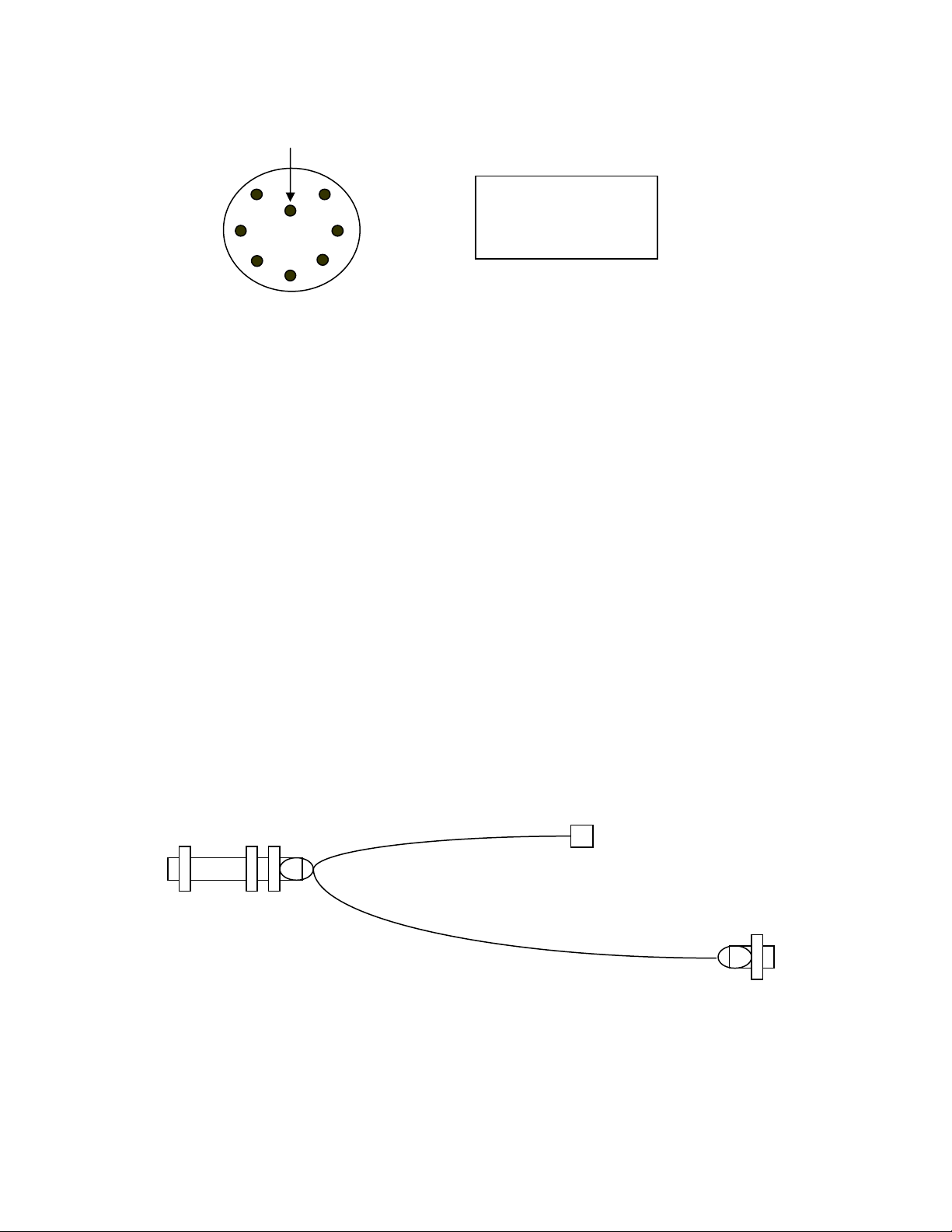
Table 1 provides the pin numbers and functions for the male connector on the
transponder/transceiver (MCBH8M). The user should match the pin numbers on Table 1
with those in Figure 1.
Table 1: Male Connector Pin Assignment
male pin number pin function DB9 pin number DB25 pin number
1 input data 3 2
2 output data 2 3
3 battery ( + ) NA NA
4 Ground 5 7
5 Reserved NA NA
6 Reserved NA NA
7 battery ( - ) NA NA
8 Trigger out NA NA
NA = not applicable
Version 5000.6.2
Page 34
33
Pin 7
Pin 8
Pin 1
Pin 2
Pin 6
Pin 5
8-conductor male
connector viewed
facing the connector
Figure 1
The trigger out pin sends out 3.3 volts logical signal in the “Electrical Trigger” mode.
This signal can be send to user’s cable, e.g. ROV cable, to trigger the responder.
RS-422 Option
If the cable from the transceiver to the PC is relatively long and the EMI is relatively
strong in the working environment, RS-422 may be the proper choice for connection as
oppose to RS-232.
LinkQuest provide an RS-232/RS-422 converter as an option. The converter is used to
connect a PC (or other RS-232 instruments) to the transceiver with the RS-422 option.
Please refer to section 8.0 for the type and function of the transceiver’s connector.
The following figure is a plot of the converter.
DB9 Female Converter Power Connector
Transceiver to RS-422 12 VDC, Plus on Center Pin
2-conductor
cable
DB9 Female
RS-232 To PC
3-conductor
cable
Figure 2
Version 5000.6.2
Page 35

34
The power supply of the converter is 12 VDC. The current is less than 40 mA.
The center pin of the power supply connector is plus.
Table 2 shows the pin assignment for the link between the RS-232 connector and the
PC (i.e. this is compatible with the standard PC RS-232 connector assignment.). The
3-conductor cable carries the data to and from the transceiver as well as the ground
connection.
Table 2: RS-232 connector to the PC
DB9 Pin
Number
1 NA
2 Data output from the transceiver
3 Command input to the transceiver
4 NA
5 Ground
6 NA
7 NA
8 NA
9 NA
NA = not applicable
The pin assignment between the transceiver’s 8-conductor male connector and the
RS-422 converter’s pin assignment is provided in Table 3. Note that the RS-422 pin
assignment is compatible with the RS-232 pin assignment (i.e. the cable with the RS422 connector can also be used by the system with the RS-232 connector).
Pin function
Table 3: Transceiver to RS-422 converter
Transceiver Pin
Number
1 RB 3
2 TA 2
3 Battery ( + ) NA
4 Ground 5
5 TB 7
6 RA 8
7 Battery ( - ) NA
8 Trigger out NA
NA = not applicable
RS-422
Pin Function
DB9 Pin
Number
Version 5000.6.2
Page 36

35
**IMPORTANT**
If the RS-232/RS-422 communication line is disconnected or the power to the
RS-232/RS-422 converter is disconnected while the transceiver is still powered on,
junk data may be generated and transmitted to the underwater instruments. These
junk data may be misinterpreted as a transceiver command. Therefore, it is very
important to disconnect the transceiver power prior to disconnecting the RS-232,
RS-422 or RS-232/RS-422 converter power.
Version 5000.6.2
Page 37

36
Appendix D: Transponder Cable and Connector Specification
The 8-conductor MICRO 8 SUBCONN connector used by the transponders can be
purchased from MacArtney Offshores, Inc. worldwide. They have offices in Denmark,
Norway, Sweden, France and the United States. The part number of this connector is
MCBH8M (male connector)
The proper matching 8-conductor MICRO 8 SUBCONN cable connector can also be
purchased from MacArtney Offshores, Inc. The part number of this matching cable
connector is
MCIL8F (female cable connector)
The 8-conductor MICRO 8 SUBCONN transceiver/transponder cable should have
shielding for proper grounding. The cable with the 8-conductor MICRO 8 SUBCONN
connector can be ordered from LinkQuest Inc. For reliable RS-232 communication it is
advised that the maximum cable be less than 20 meters. The user may choose to
configure the other end of the cable (without the 8-conductor connector) to DB9 or any
other user preferences.
Table 1 provides the pin numbers and functions for the male connector on the
transponder (MCBH8M). The user should match the pin numbers on Table 4 with those
in Figure 1.
Table 1: Male Connector Pin Assignment
male pin number pin function DB9 pin number
1 input data 3
2 Output data 2
3 Battery ( + ) NA
4 ground 5
5 reserved NA
6 Trigger in NA
7 battery ( - ) NA
8 Power up NA
NA = not applicable
Version 5000.6.2
Page 38

37
Pin 7
Pin 8
Pin 1
Pin 2
Pin 6
Pin 5
8-conductor male
connector viewed
facing the connector
Figure 1
For all transponder models, pin 8 must be connected to pin 3 for proper transponder
operation. For models with internal battery, this can be accomplished by plugging the
power-up plug shipped with the transponder into the transponder male connector. If a
custom cable (not provided by LinkQuest) is used, pin 8 and pin 3 need to be connected
for the proper operation of the transponder.
The power-up plug should not be plugged into the transponder during storage. Otherwise
the transponder will be powered on and the battery will be drained.
If an external 24-volt power supply is connected to pin 3 and pin 7, the external power
supply will be used instead of the internal battery. In this case the power up pin (pin 8)
also needs to be connected to pin 3 to power up the inside transponder circuit.
Responder Mode
The “trigger in” pin takes 3.3 volt or 5 volt logic signal with an input resistance larger
than 2k ohms. The transponder, if configured at the “Responder” mode, will send out
acoustic signal to the transceiver when the trigger signal is received.
Please note the “Responder” mode only works for address 1 and only when the
transponder is externally powered. When the external power is cut off, the transponder
will automatically switch to the “Transponder” mode and use internal power supply in
about 20 seconds. If the external power supply is restored, the transponder will switch
back to the “Responder” mode in about 20 seconds.
External Power Supply Connection Requirement
An external power supply connected to pin 3 can be used for the transponder. In this case
the following two wiring requirements need to be satisfied to make sure that the
transponder will always switch to internal battery power supply when the external power
fails.
Version 5000.6.2
Page 39
38
+
_
26 to 28 V
1. Make sure the power-up pin (pin 8) is connected to pin 3.
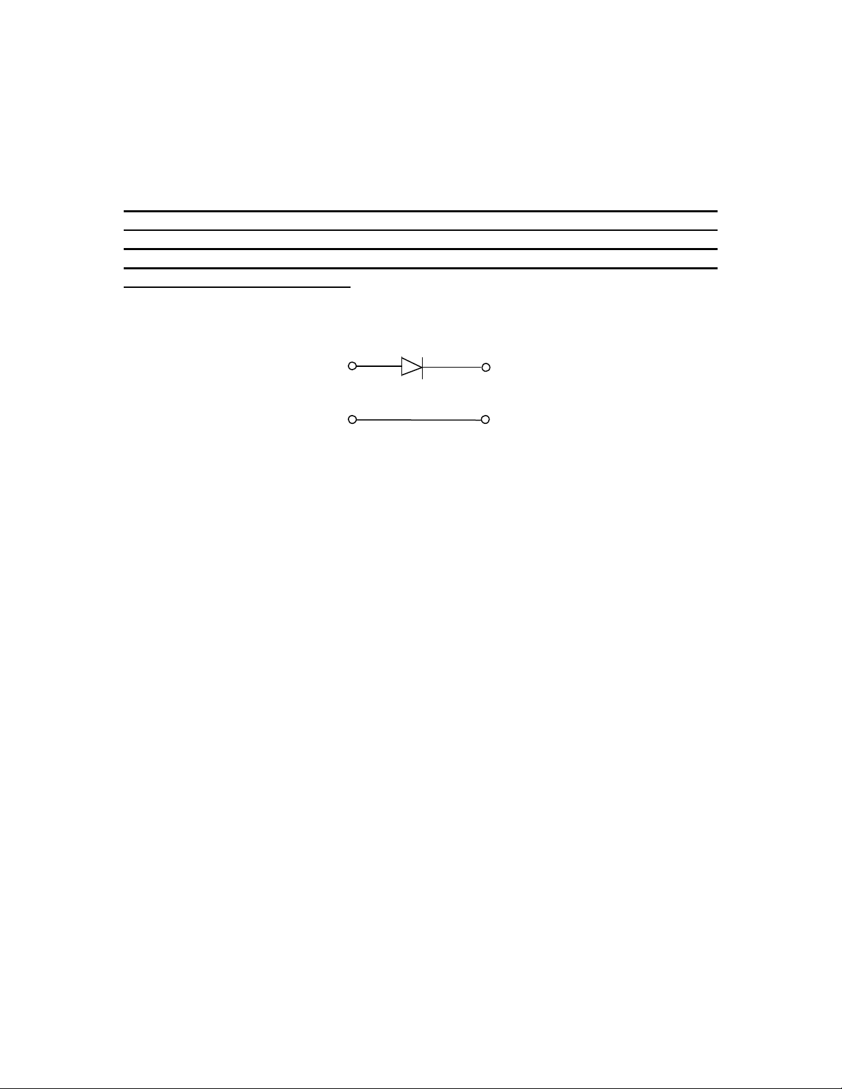
2. Connect a diode (SR206) in series with the external power supply before
connecting it to pin 3 (refer to Figure 2).
Important: If the above diode is not used the internal power will be used when the
voltage of the external power is lower than the battery voltage or the external power
is disconnected. However if the external power is shorted to the ground the
transponder will be powered off. The diode in series with the external power supply
makes sure this will not happen.
Power Supply
SR206
5010C Transponder
Figure2
Version 5000.6.2
Page 40

39
Appendix E: Error Messages
Error 1: “RS232 has timed out.”
The device has no valid RS232 data output to the computer. Use the “Test” feature of
TrackLink Navigator software to see if the device functions properly.
Error 2: “RS232 input is lost.”
The RS232 communication between the device and the computer is having problems.
Check if the serial link between the device and the computer functions properly.
Error 3: “Transceiver has no responses.”
Check if the transceiver is properly connected and powered on.
Error 4: “Conf table has no entry for GPS.”
The user needs to specify GPS serial port on Configuration->Serial Ports menu.
Error 5: “Conf table has no entry for Compass.”
The user needs to specify Compass serial port on Configuration->Serial Ports menu.
Error 6: “Conf table has no entry for Transceiver.”
The user needs to specify Transceiver serial port on Configuration->Serial Ports menu.
Error 7: “Conf table has no entry for VRU.”
The user needs to specify VRU serial port on Configuration->Serial Ports menu.
Error 8: “Transceiver has RS232 line error.”
The user needs to check the RS232 connection between the transceiver and the computer.
Error 10: “Conf table has no entry for serial output.”
The user needs to specify serial port for serial data output on Configuration->Serial Ports
menu.
Error 11: “Transceiver has timed out.”
The transceiver has no valid RS232 data output to the computer. Use the “Test” feature of
TrackLink Navigator to see if the transceiver functions properly.
Error 12: “Invalid Range.”
It should occur occasionally. If this happens frequently, contact LinkQuest for support.
Error 13 - 18: “Cannot open file.”
Internal file conflicts. If the user encounters one of the error messages 13-18 and other
errors, and after restarting the program and rebooting the computer, the TranckLink
Navigator software still does not work properly, restore database function can help the
user to restore the database using the default configuration.
Version 5000.6.2
Page 41

40
“Restore database” command is on the Help menu of the TrackLink Navigator software.
Error 19: “No valid GPS input.”
The user needs to check the serial port setup for the GPS on Configuration->Serial Ports
menu. There is also possible that the GPS is not configured properly or does not function
properly. Use the “Test” feature of TrackLink Navigator to check whether the GPS
functions properly.
Error 20: “No valid Compass input.”
The user needs to check the serial port setup for the compass on Configuration->Serial
Ports menu. The user needs to check the serial port setup for the Compass on
Configuration-> Serial Ports menu. There is also possible that the Compass is not
configured properly or does not function properly. Use the “Test” feature of TrackLink
Navigator to check whether the Compass functions properly.
Error 21: “No valid VRU input.”
The user needs to check the serial port setup (serial port and baud rate) for the
VRU/Motion Sensor on Configuration->Serial Ports menu. The user needs to check the
serial port setup for the VRU/Motion Sensor on Configuration->Serial Ports menu.
There is also possible that the VRU/Motion Sensor is not configured properly or does not
function properly. Use the “Test” feature of TrackLink Navigator to see if the Compass
functions properly.
Error 23: “Cannot open serial port for VRU.”
Check if the port for VRU is valid.
Error 24: “No open serial port for transceiver.”
Check if the port for transceiver is valid.
Error 25: “Cannot open serial port.”
Check if the serial port is valid.
Error 26: “Cannot open serial port for GPS.”
Check if the port for GPS is valid.
Error 27: “Cannot open serial port for Compass.”
Check if the port for Compass is valid.
Error 28: “Transceiver error.”
Cannot set transceiver parameter.
Error 29: “TrackLink Navigator error.”
Save all the files in C:\tracklink directory and contact LinkQuest for support.
Error 30: “GPS driver is not available.”
The GPS driver is not purchased. Contact LinkQuest for support.
Version 5000.6.2
Page 42

41
Error 31: “Compass driver is not available.”
The compass driver is not purchased. Contact LinkQuest for support.
Error 32: “VRU driver is not available.”
The Motion Sensor/VRU driver is not purchased. Contact LinkQuest for support.
Error 33: “Serial output driver is not available.”
The serial output driver is not purchased. Contact LinkQuest for support.
Error 34: “Cannot open serial port for output.”
Check whether the port for serial data output is valid.
Error 37: “Cannot open file.”
See Error 13 -18.
Error 38 - 44: “Cannot set parameter.”
Contact LinkQuest for support.
Error 47: “Cannot open serial port for Acoustic Communication.”
Check if the serial port for acoustic communication is valid.
Error 48: “Acoustic Communication driver is not available.”
The acoustic communication driver is not purchased. Contact LinkQuest for support.
Error 49 - 50: “Cannot open file.”
See Error 13 -18.
Error 51: “Conf table has no entry for Acoustic Communication.”
Check “Configuration” -> “Serial Port” to see if the serial port for the acoustic
communication is selected.
Error 52 - 53: “Cannot open file.”
See Error 13 -18.
Error 54 - 56: “Cannot set parameter.”
Contact LinkQuest for support.
Error 58: “RS232 line is NOT CLEAN.”
Check the ground of the computer and etc. This problem has to be addressed before
tracking any target.
Error greater than 64 and less than 100
Error codes those are greater than 64 and less than 100 are system errors. Power off
transceiver for 10 seconds, then power on again. Please power off the transceiver first,
and then close the warning window on the interface.
Version 5000.6.2
Page 43
42
Error 127 - 128: “Motion sensor input error.”
Input data from VRU/motion sensor are incorrect.
Error 180 - 182: “Motion sensor input error.”
Input data from VRU/motion sensor are incorrect.
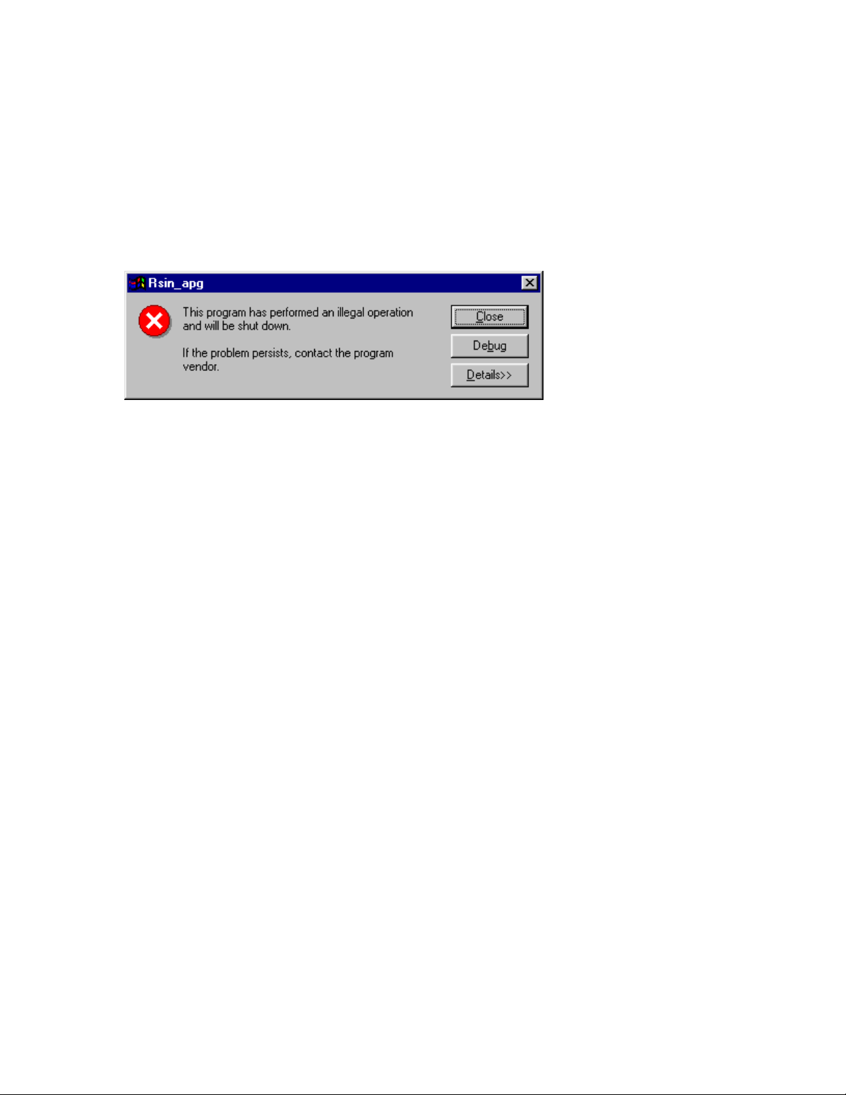
Error messages related to difficulty in opening a serial port (COM port) and error
messages similar to the following:
It is very likely that one or more serial ports are not released after the TrackLink software
or other user software exits. Please reboot the computer if restarting the TrackLink
Navigator software does not address the problem.
Version 5000.6.2
Page 44

43
Appendix F: Transponder Battery Core Replacement
1. Introduction
The replacement of the battery core involves three main parts — the anodized
aluminum transponder housing, the battery pack and the battery core inside the
battery pack. The battery core is replaceable and may be purchased directly through
LinkQuest Inc.
To prevent water leakage into the pressure housing when replacing the battery core,
the user should follow the procedures below for removal and re-installation with
extra caution. Since the procedures for re-installation is similar to the procedures for
removal, the user should take good notes during the removal process to help with the
re-installation process.
Note: The pictures are for illustration purpose. The exact color and size of the
system may vary.
2. Supplies and tools needed for battery core replacement
Please make sure the following supplies and tools are readily available:
• New battery core (refer to specification)
• Voltmeter
• Wooden chisel
• A clean piece of paper (letter size or greater)
• Transparent tape
• Plastic ties for securing wires
• Marker (e.g. small pieces of colored tape)
• Two flat stands of equal thickness for placing the battery pack vertically (e.g.
books).
• Pliers, wrenches and hammer
3. Determining the condition of the old and new battery cores
Before replacing the battery core, the customer should check the voltage of the
battery core inside the housing to determine the condition of the battery core. The
nominal voltage of the ABP16D battery core used in TN5010C transponder is 24
volts.
1) Power on the transponder using the 2-meter testing cable (do not use the power on
plug) by connecting “power on” pin to power positive. (Usually these two are
connected by the manufacturer.) Open the TrackLink software and go to
“Transponder” -> “Mode”. Set the transponder to “Responder” mode. Using a
Version 5000.6.2
Page 45

44
voltmeter (it is better to use a digital meter) to measure the voltage of the old
battery core from the red and black power connectors.
2) If the voltage falls below 16 volts, the battery core needs to be replaced in order
for the transponder to function properly.
3) Before replacing the old battery core, measure the voltage of the new battery core.
For the new battery core purchased from LinkQuest (refer to specification), the
positive and negative leads of the 2-pin connector are depicted in Figure 1. The
new battery core should register a voltage of at least 24 volts for ABP16D (the
new battery cores may register a voltage that is 1 or 2 volts above the nominal
voltage).
Figure 1: Diagram of the 2-pin connector viewed facing the connector
4. Procedures for removing the TN5010 existing battery core
The end cap of the battery pack contains two O-rings. These O-rings must be
protected from contamination or damage at all times during the replacement
procedures.
1) Place the transponder securely on a flat surface with ample work area.
2) Before removing the screws on the end cap, prepare a clean sheet of paper with an
8cm hole in the middle. This paper will be used to protect the two O-rings from
contamination while the battery core is being replaced.
3) Remove the 6 screws that hold the end cap and retain the screws, nuts and
washers for later use. Be sure to make a note of the order of the nut and the
washers on both sides of the screw. The order of the washers is critical to proper
operation of the transponder.
4) After the 6 screws are removed, carefully open (open slightly) the end cap using
the wooden chisel and a hammer (refer to figure 3). Please be sure never use a
metal screwdriver. Be careful not to stick the wooden chisel more than 1cm into
the end cap so as not to damage the O-rings sitting inside the end cap. The user
should open the end cap by working evenly on all sides of the end cap.
Version 5000.6.2
Page 46

45
5) Before pulling out the end cap use a colored marking tape to align the hole on the
end cap with the hole on the bottom of the housing (please refer to figure 4). If
the holes on the end cap are not properly aligned with the holes on the bottom of
the housing, the user will not be able to re-install the battery pack properly.
6) Using both hands, pull the end plate 4cm out of the housing (see figure 4). It is
important that the user does not rotate the end plate relative to the housing while
the end plate is being pulled out.
7) Locate the 14-pin ribbon cable within the 4cm gap between the end plate and the
housing (see figure 4). If the 14-pin ribbon cable is located in the bottom portion,
the user may rotate the housing and the end cap until the 14-pin ribbon cable
appears on the top for easier access. It is important that the end cap and the
housing be rotated simultaneously to avoid any damage.
8) Remove the transparent tape that holds the 14-pin ribbon cable to the battery
pack.
9) Pull the 14-pin connector from its socket (see figure 5). Make sure to hold both
side of the 14-pin connector before disconnecting the connector.
10) Using transparent tape affix the disconnected 14-pin connector onto the housing
as shown in figure 6. Make sure the 14-pin connector is affixed just above the
long screw of the battery pack; otherwise damage will occur during reinstallation.
11) Cover the O-ring, which is on the cap, with the transparent tape.
12) Pull out the rest of the battery pack without rotating the end cap. The battery pack
is long so make sure to use both hands to support both ends of the battery pack
while its being pulled out.
13) Place the removed battery pack vertically on two stands with the end cap on the
bottom (see figure 7). Make sure the 8-conductor connector underneath the end
cap is not touching the table.
14) Remove the plastic tie that holds the 2 wires to long screw of the battery pack and
disconnect the 2-pin connector from its socket at the bottom of the battery core
(see figure 8).
15) Remove the four nuts on the top of the battery pack and remove the circular plate
that holds the battery core.
16) Remove the battery core from the battery pack. Make a note of the location of the
2 wires on the battery core relative to the battery pack.
Version 5000.6.2
Page 47

46
5. Procedures for installing the TN5010 battery core
After the old battery core is removed from the battery pack we are now ready to
install the new battery core in the battery pack and re-install the battery pack into the
housing.
1) Slide the new battery core onto the battery pack making sure that the 2-wires are
at the same position as they were when the old battery core was on the battery
pack.
2) Re-connect the 2-wire connector to its socket at the bottom of the battery core.
3) Secure the 2-wire leads to the long screw of the battery pack using a plastic tie.
4) Replace the circular metal plate on the top of the four long screws and replace the
four nuts that hold the circular metal plate. It is important that the 4 nuts are not
over tightened (see figure 9).
5) Replace the tape around the 2-pin connector and 14-pin ribbon cable.
6) Remove the tape on the housing cap O-ring.
7) Examine the two O-rings on the end cap. The O-rings must be completely free
of contaminants or damage. If either O-rings is contaminated or damaged, the
O-rings must be cleaned or replaced by a qualified professional. It is better to
place some silicon grease on the O-rings for sealant purpose. LinkQuest uses
DOW CORNING Compound 111.
8) Hold the battery pack securely with both hands and start inserting the battery pack
into the housing. Make sure the holes on the end cap are properly aligned
with the holes on the bottom of the housing using the colored markers placed
earlier.
9) Do not insert the battery pack all the way into the housing. Leave 4cm gap
between the end cap and the housing (see figure 4).
10) Reconnect the 14-pin connector to its socket (see figure 10) and secure the ribbon
cable flat onto the battery pack using transparent tape. The ribbon cable must not
bulge up above the surface of the battery pack otherwise the ribbon cable will
obstruct with the final re-installation.
11) Measure the voltage from the bottom of the end plate using procedures in section
3. Make sure the voltage is correct (refer to specification).
12) There are two copper springs (see figure 4) on each side of the end plate. These
copper springs are used for grounding and must have a good electrical contact
Version 5000.6.2
Page 48
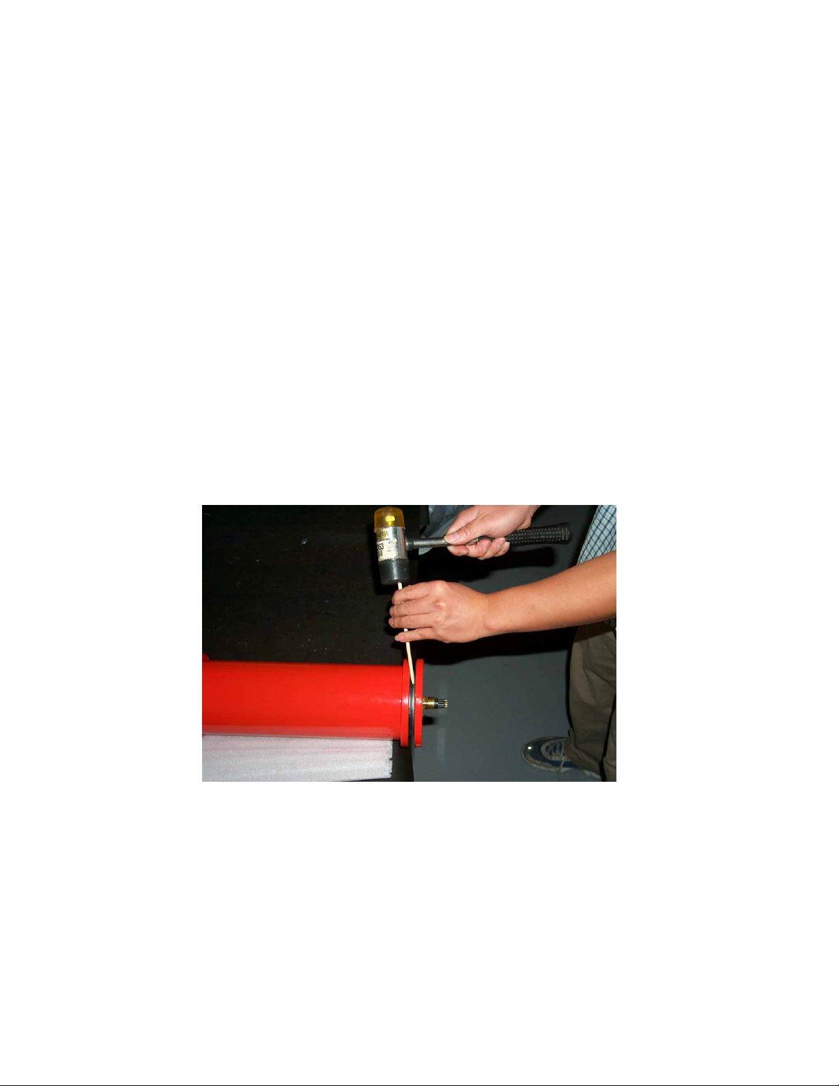
47
with the inside wall of the housing. Adjust the copper springs so that they are
neither too far outward (which obstruct with the re-installation of the battery pack
into the housing) nor too far inward (which causes poor or no electrical contact
with the inside wall of the housing).
13) It is better to tape a small packet of desiccant on the battery core.
14) Push the battery pack all the way into the housing while making sure the big O-
ring on the end cap is securely fitted inside the O-ring groove (see figure 11).
Also make sure that the holes on the end cap are perfected aligned with the holes
on the housing. The user may need to give the end cap a firm push to insert the
last centimeter of space between the end cap and the housing (due to the tight fit
of the bore O-ring).
15) Replace the six screws along with the nuts and washers that were set-aside during
the removal process. The washers and the nuts must be placed in the correct
order as they were before removal. If the user forgets the positions of the
washers, use the positions of the washers on the other end of the housing as a
point of reference.
Figure 3
Version 5000.6.2
Page 49
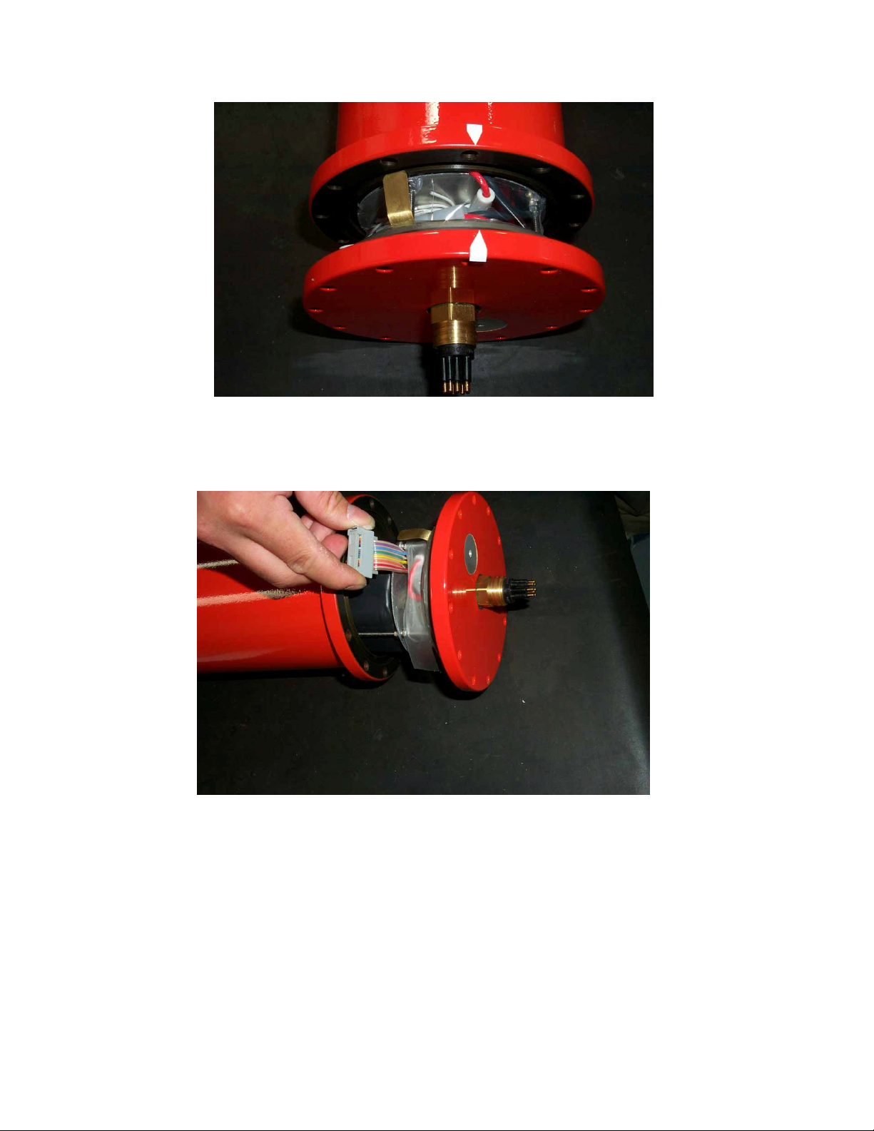
48
Figure 4
Figure 5
Version 5000.6.2
Page 50
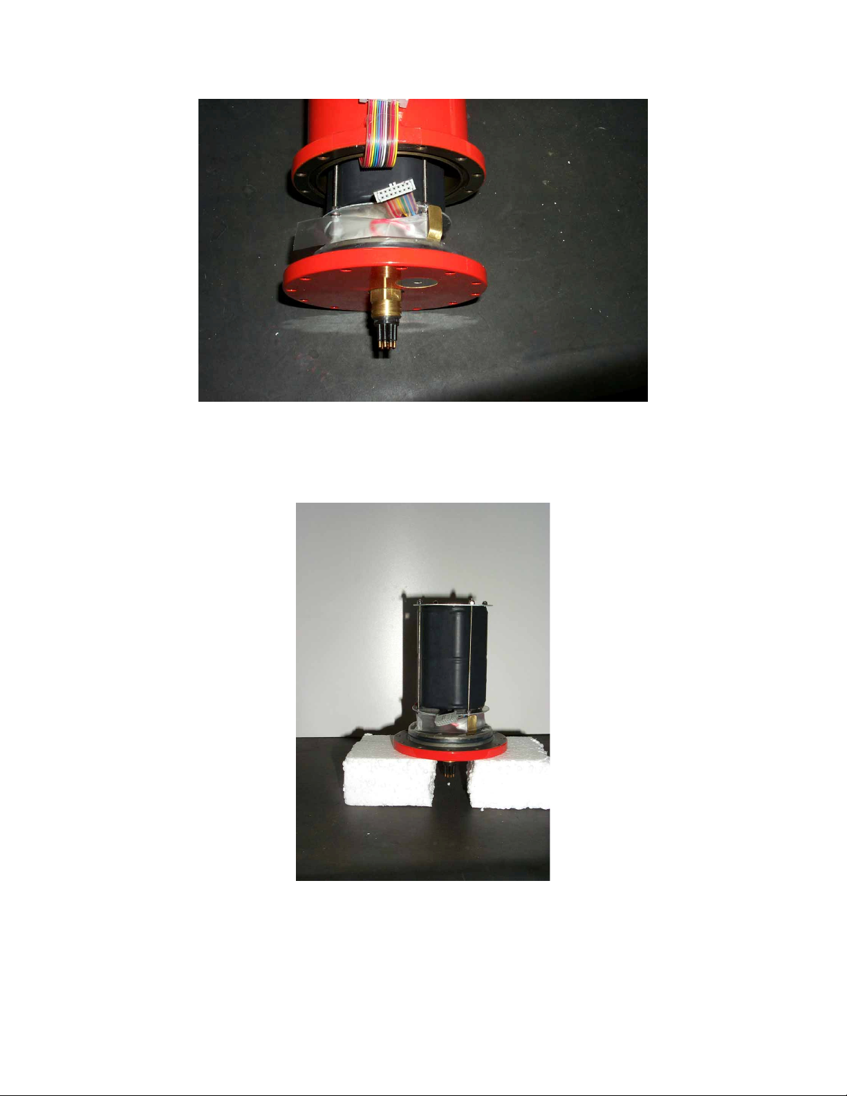
49
Figure 6
Figure 7
Version 5000.6.2
Page 51
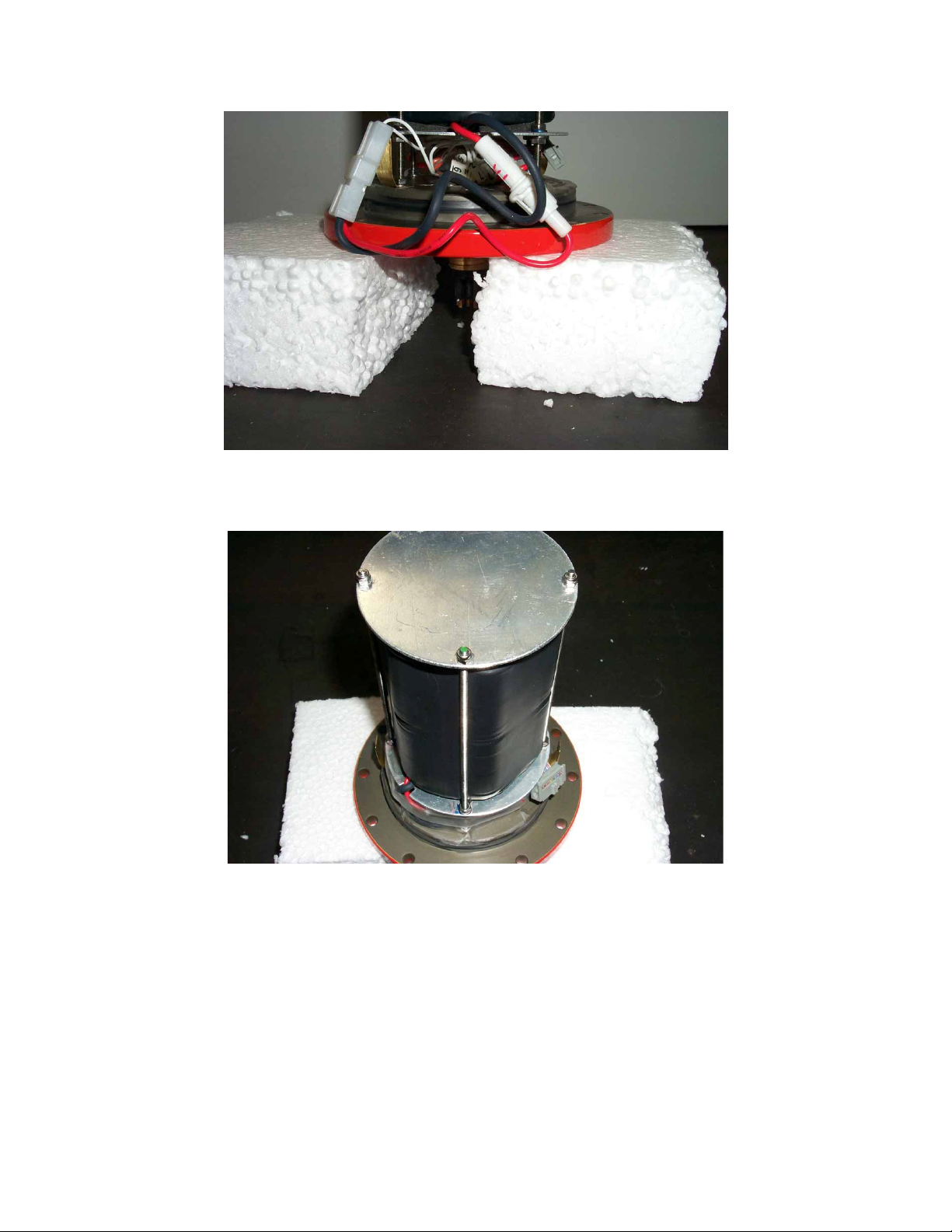
50
Figure 8
Figure 9
Version 5000.6.2
Page 52
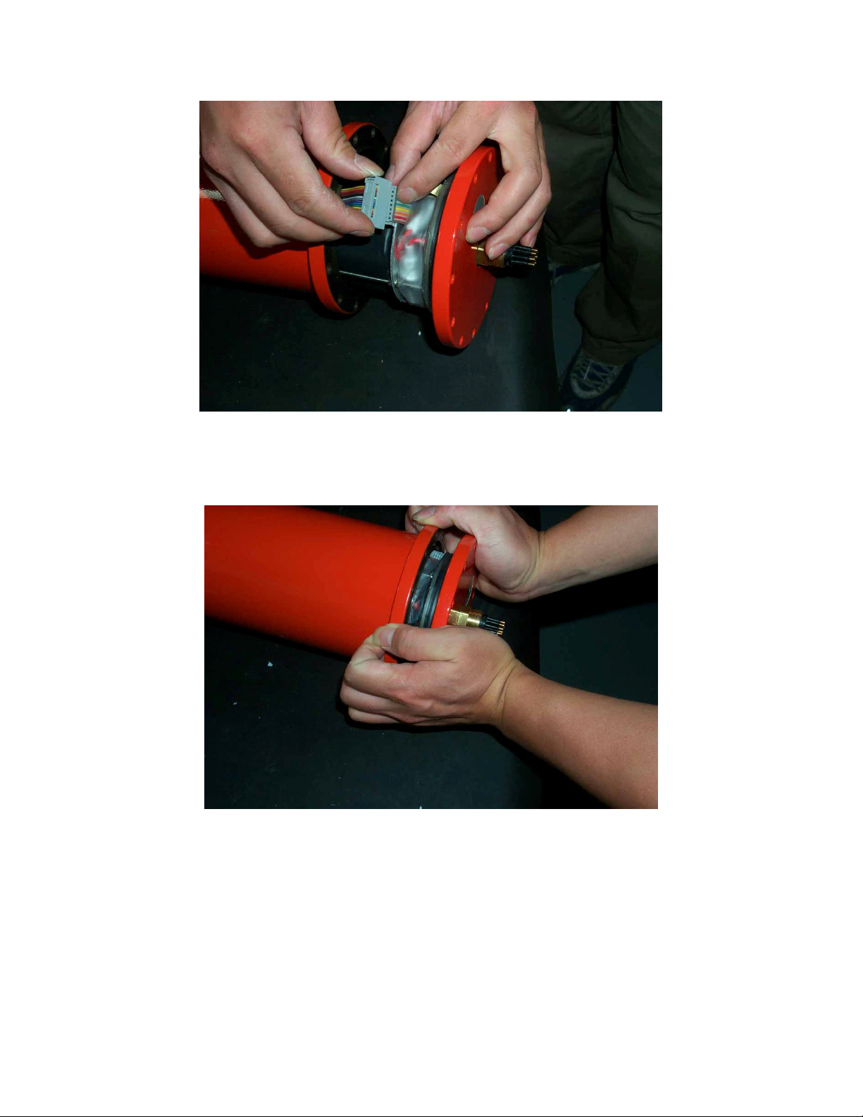
51
Figure 10
Figure 11
Version 5000.6.2
Page 53

52
6. Specifications
Nominal Voltage: ABP16D: 24V (24 ~ 25.6V)
Bore O-Ring: Parker O-Ring Part # 2-237
Surface O-Ring: Parker O-Ring Part # 2-248
Version 5000.6.2
Page 54
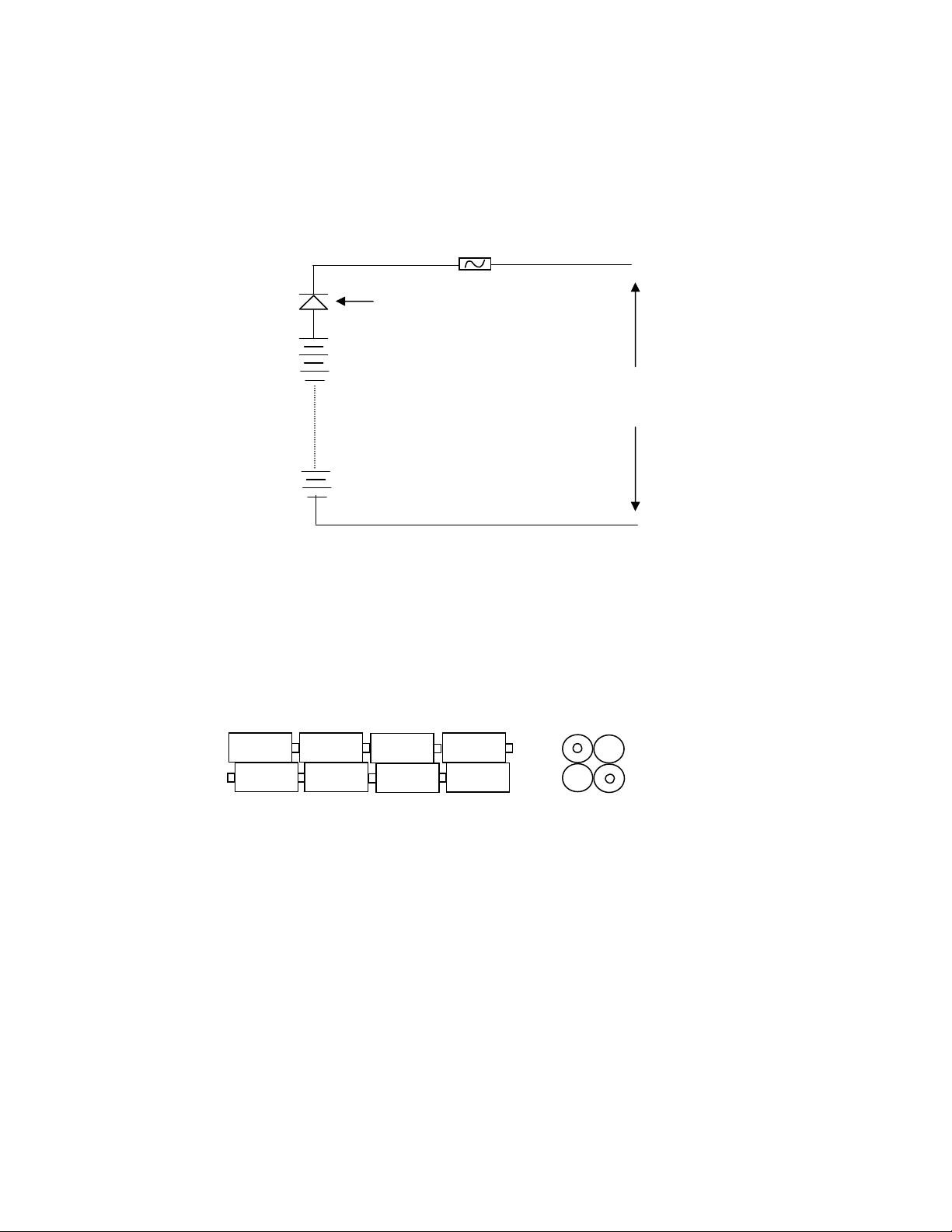
53
Appendix G: Make Your Own ABP16D Battery Pack
SR105
DC 24V
+
_
The user may choose not to buy the battery pack from LinkQuest and instead of make
his/her own battery pack using 16 “D” size alkaline batteries. The schematic diagram for
the battery core is depicted in Figure 1.
16 serially connected D size batteries are packaged as four layers and four columns as
depicted in Figure 2. A diode (SR105) and a 1A fuse are in serial with the battery positive
output.
The negative and positive leads should be connected to 200mm long wires (24-18AWG)
ended with the specified 2-pin connector (see Figure 3). The two ends of the battery pack
should be secured with circular cardboards as in Figure 3. Once the wires are all
connected and the batteries are properly arranged, wrap the outside of the battery core
using a “heat shrink tubing”. Note that the “heat shrink tubing” is slightly longer than the
length of the battery core for proper fitting. Make certain that the finished battery core
has the proper dimension, 80 x 250; otherwise the battery core will not fit properly.
1.5V x 16
1A
Figure 1
Figure 2
Version 5000.6.2
Page 55
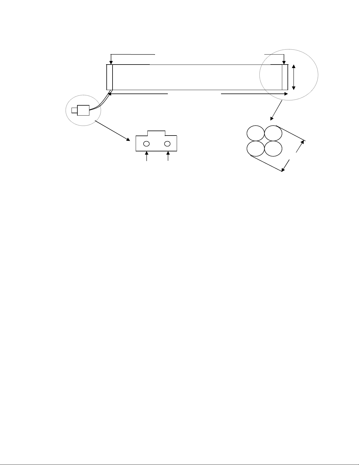
54
2-pin connector
Viewed
facing the end of the
battery core
80 mm
-
Thin circular cardboard (80mm diameter)
(thickness of cardboard not drawn to scale)
Battery Core
65 mm
200mm long wires
(24 - 18AWG)
250 mm
1
2
Viewed facing the connector
(see specification for part number)
without the cardboard
Figure 3
Version 5000.6.2
Page 56

55
Limited Warranty
LinkQuest Inc. warrants its new products against defects in material and
workmanship for a period of 12 months from the date of delivery. LinkQuest Inc. will
replace or repair free of charge any defective part or any product returned to its
factory in San Diego, California, USA or other location(s) designated by LinkQuest
Inc., subject to the following terms and conditions:
This warranty covers only product defects from normal use and service. The product
should only be used under non-corrosive environment that may include both fresh and
salt water. The product housing must be protected against abrasion that may damage
the housing’s protective coatings. This product is equipped with corrosion preventive
substance (i.e. zinc anode). If the product is electrically connected to other
underwater instruments, such electrical connection must be made such that the effect
of the anti-corrosive substance is not diminished. LinkQuest Inc. does not warrant
that the product will be free from error or that such product will meet your specific
requirements.
The limited warranty is void if the housing of the transceiver is opened. The limited
warranty is also void if the transponder housing is opened for any purpose other than
changing of batteries or the electronics of the transponder is tampered. This limited
warranty does not apply if the product has been subjected to physical abuse, improper
installation and usage, or modification.
The limited warranty does not cover any shipping charges and customs fees
associated with the repair.
To obtain warranty service the warranty holder must first obtain a return invoice
number from LinkQuest Inc. by calling the phone number listed below. The product
must be returned with insurance and shipping prepaid, to LinkQuest Inc. at the
address below, in its original packaging or a suitable equivalent, along with a written
description of the problem.
EXCEPT FOR THE EXPRESS LIMITED WARRANTY STATED HEREIN,
LINKQUEST INC. MAKES NO OTHER WARRANTIES OR
REPRESENTATIONS EITHER EXPRESSED OR IMPLIED, INCLUDING,
WITHOUT LIMITATIONS, ANY WARRANTIES OF MERCHANTABILITY
AND FITNESS FOR ANY PARTICULAR PURPOSES WHATSOEVER. IN NO
EVENT SHALL LINKQUEST INC. BE LIABLE FOR ANY LOST PROFITS,
LOST OR INACCURATE DATA, LOSS OR DAMAGES, SPECIAL DAMAGES,
CONSEQUENTIAL DAMAGES, OR INCIDENTAL DAMAGES, REGARDLESS
OF WHETHER LINKQUEST INC. HAS NOTICE OF THE POTENTIAL OF ANY
SUCH LOSS OR DAMAGE. IN ANY EVENT, LINKQUEST INC.’S LIABILITY
SHALL NOT EXCEED THE AGGREGATE PAYMENTS RECEIVED BY
LINKQUEST UNDER THIS AGREEMENT.
Version 5000.6.2
Page 57

56
LinkQuest Inc.
6749 Top Gun Street, Suite 100
San Diego, CA 92121
USA
Tel: (858) 623-9900, 623-9916, 623-9919
Fax: (858) 623-9918
Email: [email protected]
Version 5000.6.2
Page 58

57
LINKQUEST END USER LICENSE AGREEMENT FOR FIRMWARE,
SOFTWARE AND DOCUMENTATION
========================================================================
LinkQuest Inc. June 2003
TrackLink System DSP Firmware & PC Tracking Software
Copyright (c) 2002 LinkQuest Inc.
All Rights Reserved
========================================================================
-----------------------------------------------------------------------BY INSTALLING, LOADING OR USING THE SOFTWARE, YOU ARE CONSENTING TO BE
BOUND BY THIS AGREEMENT. IF YOU DO NOT AGREE TO ALL OF THE TERMS OF THIS
AGREEMENT, DO NOT COPY OR INSTALL THIS SOFTWARE.
------------------------------------------------------------------------
GRANT.
Subject to the terms and conditions of this License Agreement, LinkQuest
Inc. ("LinkQuest") hereby grants you a non-exclusive license to use its
accompanying firmware, software and documentation ("Software") for the
limited purpose of installing and operating the TrackLink system and for
no other purpose.
GEOGRAPHIC LIMITATION.
You may not copy or use the Software in any country or jurisdiction
where applicable law requires the Software or this License Agreement to
be in a language other than English.
SCOPE OF GRANT.
The Software is contained in either a dedicated set of files and folders
when provided on a CD-ROM or a self-extracting executable file. You must
follow LinkQuest's installation instructions to load the Software on
your system. You may make a backup copy of the files for your own use.
The TrackLink tracking software only functions with the TrackLink
transceiver purchased by the customer. You shall not use the tracking
software with any other TrackLink transceiver except the one you
purchased.
You may not:
• Permit others to use the Software.
• Modify, translate, reverse engineer, decompile, disassemble (except
to the extent applicable laws specifically prohibit such
restriction), or create derivative works based on the tracking
Software, DSP firmware or its interface specifications;
• Remove any proprietary notices or labels pertaining to the Software.
Version 5000.6.2
Page 59

58
TITLE.
Title, ownership rights, and intellectual property rights in the
Software/Firmware shall remain in LinkQuest and/or its suppliers.
LinkQuest and/or its suppliers reserve all rights not expressly granted
herein.
The Software is protected by the copyright laws and treaties. Title and
related rights in the content accessed through the Software is the
property of the applicable content owner and may be protected by
applicable law.
This license gives you no rights to such content.
TERMINATION.
LinkQuest may terminate this license at any time, without requirement of
cause, by giving you written notice.
The license will automatically terminate immediately if you use the
Software for any purpose not authorized by the above license, or if you
fail to comply with the terms and conditions of this license agreement.
On termination, you must destroy all copies of the Software and related
documentation.
MISCELLANEOUS.
This Agreement represents the complete agreement concerning this license
and may be amended only by a writing executed by you and by LinkQuest.
If any provision of this Agreement is held to be unenforceable, such
provision shall be reformed only to the extent necessary to make it
enforceable. This Agreement shall be governed by the laws of the State
of California, United States of America (except for conflict of law
provisions). The application of the United Nations Convention of
Contracts for the International Sale of Goods is expressly excluded.
U.S. GOVERNMENT RESTRICTED RIGHTS.
If you are acquiring Software on behalf of any part of the
United States Government, the following provisions apply:
The Software is deemed to be "commercial software" and "commercial
software documentation." Any use, modification, reproduction, release,
performance, display, or disclosure of the Software by the United States
Government or any of its agencies shall be governed solely by the terms
and conditions of this License Agreement, and shall be prohibited except
to the extent expressly permitted by the terms and conditions of this
License Agreement.
Version 5000.6.2
 Loading...