


MediaTek LinkIt™ Smart 7688
Developer's Guide
Specifications are subject to change without notice.
Version: 1.1
Release date: 22nd February 2016
© 2015, 2016 MediaTek Inc.
This document contains information that is proprietary to MediaTek Inc.
Unauthorized reproduction of this information in whole or in part is strictly prohibited.

MediaTek LinkIt™ Smart 7688 Developer's Guide
© 2015, 2016 MediaTek Inc.
Page i of v
Revision
Date
Description
Document Revision History
1.0 1st December 2015 Initial Release
1.1 22nd February Updated instructions of installing the Arduino PyMata
Sketch in 6.6.5, "PyMata Approach”.
This document contains information that is proprietary to MediaTek Inc.
Unauthorized reproduction or disclosure of this information in whole or in part is strictly prohibited.

MediaTek LinkIt™ Smart 7688 Developer's Guide
© 2015, 2016 MediaTek Inc.
Page ii of v
Table of contents
1. Introduction ...................................................................................................................................................... 1
1.1. What is MediaTek LinkIt? ................................................................................................................................. 1
1.2. What is MediaTek LinkIt Smart 7688 Development Platform ....................................................... 1
1.3. Hardware Development Kits .......................................................................................................................... 1
1.4. Programming Environment ............................................................................................................................ 1
1.5. Software Development Tool .......................................................................................................................... 1
1.6. Get Started............................................................................................................................................................. 2
1.7. More Information ................................................................................................................................................ 2
1.8. Join the MediaTek Labs Ecosystem ........................................................................................................... 3
2. Hardware Development Kit ....................................................................................................................... 4
2.1. MediaTek MT7688AN Chip Specification Summary ........................................................................... 4
2.2. LinkIt Smart 7688 ............................................................................................................................................... 5
2.3. LinkIt Smart 7688 Duo .................................................................................................................................... 15
2.4. FCC, CE and NCC Certifications .................................................................................................................. 22
3. Programming Environment Guide ......................................................................................................... 23
3.1. Platform operating system.......................................................................................................................... 23
3.2. Programming Environment Overview .................................................................................................... 23
3.3. Programming Model for Different Boards ........................................................................................... 24
3.4. Network Environment ....................................................................................................................................25
3.5. Programming in C/C++ .................................................................................................................................. 26
3.6. Programming in Python ................................................................................................................................. 27
3.7. Programming in Node.js ............................................................................................................................... 28
4. Software and Tools ..................................................................................................................................... 31
4.1. Software and Tools ...........................................................................................................................................31
4.2. Supported Host Environments ...................................................................................................................31
4.3. Default OpenWrt Packages ......................................................................................................................... 32
4.4. OPKG Package Manager ................................................................................................................................ 32
4.5. System Configuration ..................................................................................................................................... 33
4.6. System Configuration tasks ....................................................................................................................... 44
4.7. File Editor and Transfer .................................................................................................................................53
5. Peripheral Programming on LinkIt Smart 7688 .............................................................................. 59
5.1. How to Access LinkIt Smart 7688 Peripheral using MRAA .......................................................... 59
5.2. How to use UPM to access sensors and peripherals ...................................................................... 66
6. Peripheral Programming on LinkIt Smart 7688 Duo ...................................................................... 67
6.1. Installing Arduino IDE ..................................................................................................................................... 67
6.2. Installing Board Support Package ............................................................................................................ 67
6.3. Installing LinkIt Smart 7688 Duo COM Port Driver............................................................................. 71
6.4. Programming model for LinkIt Smart 7688 Duo ............................................................................... 72
6.5. Programming with Primitive UART Connection ................................................................................. 75
6.6. Programming with Firmata Protocol ...................................................................................................... 77
6.7. Programming with Yun Bridge Library ................................................................................................... 89
7. How to Build Firmware and Bootloader .............................................................................................. 91
7.1. Building a firmware .......................................................................................................................................... 91
7.2. Building a bootloader .................................................................................................................................... 92
8. Troubleshooting Guide ............................................................................................................................. 94
8.1. My firmware upgrade won’t start or failed. Why? ............................................................................ 94
8.2. I can’t connect to URL mylinkit.local using a browser, why is that? ........................................ 94
This document contains information that is proprietary to MediaTek Inc.
Unauthorized reproduction or disclosure of this information in whole or in part is strictly prohibited.

MediaTek LinkIt™ Smart 7688 Developer's Guide
© 2015, 2016 MediaTek Inc.
Page iii of v
8.3. My virtual machine cannot detect the board with mylinkit.local, why? ................................ 95
8.4. I’m not able to SSH access with an error showing “Host Identification Has Changed”,
what can I do? .................................................................................................................................................... 95
8.5. There are multiple LinkIt Smart 7688 APs nearby and I’m not sure which one is mine,
how do I find out?.............................................................................................................................................. 97
8.6. My onboard flash is very slow and seems broken, why? ............................................................... 97
8.7. Why did my board failed to start up due to corrupted file system? ........................................ 98
8.8. What can I do if my onboard flash is full? ............................................................................................ 98
8.9. Why is my I2C device not working? .......................................................................................................... 98
8.10. Why does my board keep rebooting when driving a servo? ........................................................ 98
Appendix A Federal Communication Commission Interference Statement.................. 99
This document contains information that is proprietary to MediaTek Inc.
Unauthorized reproduction or disclosure of this information in whole or in part is strictly prohibited.

MediaTek LinkIt™ Smart 7688 Developer's Guide
© 2015, 2016 MediaTek Inc.
Page iv of v
Lists of tables and figures
Table 1 MT7688AN SOC Specification ............................................................................................................................... 4
Table 2 LinkIt Smart 7688 Development board buttons ......................................................................................... 6
Table 3 Wi-Fi LED blink pattern in LinkIt Smart 7688 HDK ..................................................................................... 7
Table 4 Typical power consumption scenarios ............................................................................................................ 8
Table 5 LinkIt Smart 7688 development boards specifications......................................................................... 13
Table 6 LinkIt Smart 7688 Duo Development board buttons ............................................................................. 16
Table 7 Typical power consumption scenarios ...........................................................................................................17
Table 8 LinkIt Smart 7688 Duo development board specifications ................................................................ 20
Table 9 LinkIt Smart 7688 Programming Environment Overview................................................................... 24
Table 10 OS Capabilities ........................................................................................................................................................ 31
Table 11 Packages included in the LinkIt Smart 7688 development platform ........................................... 32
Table 12 Configuration functions of the Web UI and System console ........................................................... 34
Table 13 USB and LinkIt Smart 7688 UART Pin Mapping ........................................................................................ 41
Table 14 Wi-Fi AP Encryption Type .................................................................................................................................. 50
Table 15 File Transfer Tools ................................................................................................................................................ 53
Table 16 LinkIt Smart 7688 GPIO Pin Mapping ........................................................................................................... 60
Table 17 MCU and MPU Communication ........................................................................................................................75
Table 18 Serial Pin Mapping Between MPU and MCU ............................................................................................. 78
Figure 1 LinkIt Smart 7688 development board (MPU only) ................................................................................... 5
Figure 2 Removing resistor to enable I-PEX connector ........................................................................................... 7
Figure 3 USB OTG cable ........................................................................................................................................................... 9
Figure 4 JTAG resistors on the bottom of the LinkIt Smart 7688 ...................................................................... 10
Figure 5 Moving a resistor to access JTAG mode ....................................................................................................... 11
Figure 6 LinkIt Smart 7688 Pin-out Diagram ............................................................................................................... 14
Figure 7 LinkIt Smart 7688 Duo development board (MPU + MCU) .................................................................. 15
Figure 8 JTAG resistors on LinkIt Smart 7688 Duo bottom view ....................................................................... 18
Figure 9 Moving a resistor to access JTAG mode ...................................................................................................... 18
Figure 10 LinkIt Smart 7688 Duo Pin-out Diagram ................................................................................................... 21
Figure 11 Programming models for the LinkIt Smart 7688 development platform ................................. 24
Figure 12 LinkIt Smart 7688 in AP Mode ........................................................................................................................ 25
Figure 13 LinkIt Smart 7688 in Station Mode .............................................................................................................. 26
Figure 14 Connecting LinkIt Smart development board to a computer ........................................................ 35
Figure 15 Wi-Fi LED Status .................................................................................................................................................. 36
Figure 16 Connecting to LinkIt Smart 7688 AP .......................................................................................................... 36
Figure 17 LinkIt Smart 7688 in AP mode......................................................................................................................... 37
Figure 18 LinkIt Smart 7688 Web UI Sign In ................................................................................................................. 38
Figure 19 Using SSH in Windows PuTTY ........................................................................................................................ 39
Figure 20 PuTTY Security Warning ................................................................................................................................. 40
Figure 21 System Console .................................................................................................................................................... 40
This document contains information that is proprietary to MediaTek Inc.
Unauthorized reproduction or disclosure of this information in whole or in part is strictly prohibited.

MediaTek LinkIt™ Smart 7688 Developer's Guide
© 2015, 2016 MediaTek Inc.
Page v of v
Figure 22 LinkIt Smart 7688 COM port using Serial to USB cable .................................................................... 42
Figure 23 Using UART to USB cable to access system console in Windows terminal ............................ 43
Figure 24 Firmware upgrade button .............................................................................................................................. 45
Figure 25 Selecting firmware file ..................................................................................................................................... 45
Figure 26 Firmware version ................................................................................................................................................ 46
Figure 27 Wi-Fi LED Status During Firmware Upgra ............................................................................................... 46
Figure 28 Factory Reset using LinkIt Smart 7688 Web UI .................................................................................... 47
Figure 29 Change networking setting in Web UI ....................................................................................................... 48
Figure 30 Changing to Station mode in Web UI ........................................................................................................ 49
Figure 31 LinkIt Smart 7688 in Station mode connected to a Wi-Fi AP ........................................................... 51
Figure 32 System Information in LinkIt Smart 7688 Web .................................................................................... 52
Figure 33 SCP Security Warning ....................................................................................................................................... 53
Figure 34 WinSCP login window ....................................................................................................................................... 54
Figure 35 File transfer using WinSCP ............................................................................................................................. 54
Figure 36 File transfer confirmation .............................................................................................................................. 55
Figure 37 File transfer using Samba in Windows ...................................................................................................... 56
Figure 38 Connecting to LinkIt Smart 7688 from Finder .......................................................................................57
Figure 39 Connecting to mylinkit.local server in Mac .............................................................................................57
Figure 40 Connecting as guest to mylinkit.local on Mac ...................................................................................... 58
Figure 41 MyShareFolder in Mac Finder ........................................................................................................................ 58
Figure 42 LinkIt Smart 7688 Software Architecture ............................................................................................... 59
Figure 43 Set up the Node.js application prompt..................................................................................................... 65
Figure 44 LinkIt Smart 7688 Duo Hardware Architecture .................................................................................... 67
Figure 45 LinkIt Smart 7688 Duo package URL for a custom board installation in Arduino IDE ....... 68
Figure 46 Arduino IDE Board Manager Menu ............................................................................................................. 68
Figure 47 LinkIt Smart 7688 Board Package Menu .................................................................................................. 69
Figure 48 LinkIt Smart 7688 Duo board package installed on Arduino IDE ................................................. 70
Figure 49 LinkIt Smart 7688 Duo installed on Arduino IDE ...................................................................................71
Figure 50 Arduino Preference Location ......................................................................................................................... 72
Figure 51 Driver installation ................................................................................................................................................. 72
Figure 52 Smart 7688 Duo Hardware Architecture .................................................................................................. 73
Figure 53 Software architecture ....................................................................................................................................... 73
Figure 54 Firmata Protocol ................................................................................................................................................. 74
Figure 55 Yun Bridge Library .............................................................................................................................................. 74
Figure 56 Upload Sketch in Arduino IDE ....................................................................................................................... 76
Figure 57 MPU MCU Communication Diagram .......................................................................................................... 78
Figure 58Copying example code from Github ........................................................................................................... 83
Figure 59 Uploading example sketch in Arduino IDE ............................................................................................. 83
Figure 60 Programming bootloader using AVRDUDE ........................................................................................... 89
Figure 61 Finding LinkIt Smart 7688 IP address in Station mode ...................................................................... 95
Figure 62 Host ID change warning ................................................................................................................................... 95
Figure 63 Known hosts file.................................................................................................................................................. 96
Figure 64 Finding LinkIt Smart 7688 hardware address ....................................................................................... 97
This document contains information that is proprietary to MediaTek Inc.
Unauthorized reproduction or disclosure of this information in whole or in part is strictly prohibited.

MediaTek LinkIt™ Smart 7688 Developer's Guide
© 2015, 2016 MediaTek Inc.
Page 1 of 100
1. Introduction
This section provide an overview of the MediaTek LinkIt™ development platforms and introduction
to the MediaTek LinkIt Smart 7688 development platform, which also acts as a guide to the
content of this document.
1.1. What is MediaTek LinkIt?
MediaTek LinkIt™ is a collection of development platforms designed for the prototyping of
Wearable and Internet of Things (IoT) devices. Each development platforms provide a collection of
tools, hardware and related resources to enable developers to address various Wearable and
Internet of Things (IoT) device sectors.
1.2. What is MediaTek LinkIt Smart 7688 Development Platform
The MediaTek LinkIt Smart 7688 development platform consists of a Linux Wi-Fi SOC based
development board designed to enable the prototyping of IoT devices. These devices include WiFi security web cam and sensors for the home or office, real time camera monitors for toddler and
seniors as well as cloud-based applications.
LinkIt Smart 7688 is an open development platform based on the
platform provides generous memory and storage to enable rich application development. The
platform also offers options to create device applications using Python, Node.js and C.
During prototyping the platform can take advantage of the free
to store data in the cloud. And the
get devices to market.
MediaTek Labs Partner Connect program is available to help
OpenWrt Linux distribution. The
MediaTek Cloud Sandbox service
1.3. Hardware Development Kits
The LinkIt Smart 7688 development platform offers two development boards:
• LinkIt Smart 7688: MPU only. Powered by MediaTek MT7688.
• LinkIt Smart 7688 Duo: MPU and MCU. Powered by MT7688 and ATmega32U4.
For more details on the development boards, please see Chapter 2, “Hardware Development Kit”.
1.4. Programming Environment
The LinkIt Smart 7688 development platform supports high-level languages (Python and Node.js)
and native application development (C). In addition, the MCU on the LinkIt Smart 7688 Duo can be
programmed using the Arduino API and tools.
For more details on the software development options, please see Chapter 3, “Programming
Environment Guide”.
1.5. Software Development Tool
LinkIt Smart 7688 offers Software Development Tools with utilities for tasks such as configuring
the development boards, updating board firmware, managing board support in Arduino and
installing software.
For more details on the tools and utilities provided, please see Chapter 4, “Software and Tools”.
This document contains information that is proprietary to MediaTek Inc.
Unauthorized reproduction or disclosure of this information in whole or in part is strictly prohibited.

MediaTek LinkIt™ Smart 7688 Developer's Guide
© 2015, 2016 MediaTek Inc.
Page 2 of 100
1.6. Get Started
You can find guide to getting started with LinkIt Smart 7688 on the MediaTek Lab website and
learn how to run a blink example. The step by step guide for the LinkIt Smart 7688 and LinkIt
Smart 7688 Duo board covers:
• Setting up development environment.
• Connecting to a LinkIt Smart 7688 development board.
• Upgrading the development board firmware.
• Accessing and using the system console.
• Running the Blink example on a LinkIt Smart 7688 development board.
• Connecting to the Internet.
1.6.1. Documentation, code examples and related information
There are several references available to assist with the development of software for LinkIt Smart
7688 prototypes:
• This developer’s guide, the latest copy of which is available here on the MediaTek Labs
website.
• LinkIt Smart 7688 development board pin-out diagram: This diagram provides details of
the pin breakout on the development board.
• LinkIt Smart 7688 Duo development board pin-out diagram: This diagram provides details
of the pin breakout on the development board.
In addition there are a number of resources available to assist with the creation of final device
hardware boards:
• LinkIt Smart 7688 Hardware Reference Design: This file includes:
o LinkIt Smart 7688 development board schematic and layout
o LinkIt Smart 7688 development board pin-out diagram
o MediaTek MT7688AN chipset datasheet
• LinkIt Smart 7688 Duo Hardware Reference Design: This file includes:
o LinkIt Smart 7688 development board schematic and layout
o LinkIt Smart 7688 development board pin-out diagram
o MediaTek MT7688AN chipset datasheet
Additional documentation may become available from time to time and can be found on the
development platforms
documentation page on the MediaTek Labs website.
1.7. More Information
The LinkIt Smart 7688 development platform is based on an open source Linux distribution and
supports various high-level programming languages. You can find more information about
developing for the software as follows:
• OpenWrt
• C
This document contains information that is proprietary to MediaTek Inc.
Unauthorized reproduction or disclosure of this information in whole or in part is strictly prohibited.

MediaTek LinkIt™ Smart 7688 Developer's Guide
© 2015, 2016 MediaTek Inc.
Page 3 of 100
• Python
• Node.js (JavaScript)
• Arduino
1.8. Join the MediaTek Labs Ecosystem
Wearable and Internet of Things are the next wave in the consumer gadget revolution. MediaTek
is a key player in this field, combining the best of two worlds —the existing MediaTek ecosystem
of phone manufacturers, electronic device manufacturers, and telecom operators with open,
vibrant developer and maker communities.
Whether you’re a maker, device manufacturer, student, DIY hobbyist, or programmer, you can use
this powerful yet simple platform to create something innovative. You can join the MediaTek
LinkIt ecosystem by registering on
ecosystem and creating something great together.
(The remainder of this page is intentionally left blank)
labs.mediatek.com, we look forward to you joining our
This document contains information that is proprietary to MediaTek Inc.
Unauthorized reproduction or disclosure of this information in whole or in part is strictly prohibited.

MediaTek LinkIt™ Smart 7688 Developer's Guide
© 2015, 2016 MediaTek Inc.
Page 4 of 100
MT7688AN SOC Specifications
Interface
Count
2. Hardware Development Kit
The LinkIt Smart 7688 hardware development kit (HDK) delivers two development boards: LinkIt
Smart 7688 (offering an MPU alone) and LinkIt Smart 7688 Duo (offering an MPU and MCU). The
MPU is powered by MediaTek’s MT7688AN SOC and the MCU is powered by an ATmega32U4.
The MPU supports the OpenWrt Linux distribution; it processes an application’s intensive logic
tasks and provides Wi-Fi connectivity. It supports Python, Node.js and C programming languages.
The MCU handles real-time peripheral control as well as offering the ability to run Arduino
sketches.
2.1. MediaTek MT7688AN Chip Specification Summary
Specifications of the MT7688AN SOC are shown in Table 1.
CPU MIPS24KEc (580 MHz)
Total DMIPs 580 x 1.6 DMIPs
I-Cache, D-Cache 64 KB, 32 KB
L2 Cache N/A
Memory DDR1/DDR2
16 bits
Max. 2 Gb, 193 MHz
SPI Flash 3B addr mode (max 128 Mbit)
4B addr mode (max 512 Mbit)
SD SD-XC (class 10)
RF 1T1R 802.11n 2.4GHz
Package DR-QFN156-12 mm x 12 mm
PCIe 1
USB 2.0 1
Fast Ethernet Switch 5
I2S 1
PCM 1
PWM 4
SPI 1
I2C 1
UARTLite 3
JTAG 1
Unauthorized reproduction or disclosure of this information in whole or in part is strictly prohibited.
Table 1 MT7688AN SOC Specification
This document contains information that is proprietary to MediaTek Inc.

MediaTek LinkIt™ Smart 7688 Developer's Guide
© 2015, 2016 MediaTek Inc.
Page 5 of 100
2.2. LinkIt Smart 7688
LinkIt Smart 7688 is one of the most highly integrated and compact hardware development
boards available for IoT prototyping.
2.2.1. Key Features
LinkIt Smart 7688’s key features include the following:
• 1T1R Wi-Fi 802.11 b/g/n (2.4G).
• Pin-out for GPIO, I2C, I2S, SPI, UART, PWM and Ethernet Port.
• 580 MHz MIPS CPU.
• 32MB flash and 128MB DDR2 RAM.
• USB host.
• Micro SD slot.
LinkIt Smart 7688 development board is shown in Figure 1.
Figure 1 LinkIt Smart 7688 development board (MPU only)
This document contains information that is proprietary to MediaTek Inc.
Unauthorized reproduction or disclosure of this information in whole or in part is strictly prohibited.

MediaTek LinkIt™ Smart 7688 Developer's Guide
© 2015, 2016 MediaTek Inc.
Page 6 of 100
Scenario
Button
Action
WARNING: This
will restore the
board to default
setting and
remove all user
data
2.2.2. Buttons
Description of how to use the buttons on the LinkIt Smart 7688 development board is provided in
Table 2.
One press
Reset the MPU MPU Reset Button
Reset Wi-Fi to AP
mode
Wi-Fi Reset Button
Factory reset and
enter AP mode.
Wi-Fi Reset Button
(with the board
booted up)
Press for at least 5
seconds and release
(with the board
booted up)
Press for at least 20
seconds and release
(with the board
booted up)
Press the button for
Upgrade firmware
from a USB drive
Wi-Fi Reset Button
at least 5 seconds
and release
(while the board is
powering up)
Upgrade
bootloader from a
USB drive.
Wi-Fi Reset Button
Press the button for
at least 20 seconds
and release
(while the board is
powering up)
Table 2 LinkIt Smart 7688 Development board buttons
2.2.3. LEDs
This section describes the functions of the LEDs available on the board.
• Power
The Power LED displays solid green when power is supplied to the board.
Unauthorized reproduction or disclosure of this information in whole or in part is strictly prohibited.
This document contains information that is proprietary to MediaTek Inc.

MediaTek LinkIt™ Smart 7688 Developer's Guide
© 2015, 2016 MediaTek Inc.
Page 7 of 100
Mode
Status
LED blink pattern
• Wi-Fi
The Wi-Fi LED is orange and displays the blink patterns described in Table 3.
3 blinks per second followed
With client device
AP Mode
Without client
device
by a pause for 0.5 seconds
(cycle repeats)
Off
Disconnected Off
Station
Mode
Connecting 2 blinks per second
Connected
Blinks are based on the
transmitted data package
Table 3 Wi-Fi LED blink pattern in LinkIt Smart 7688 HDK
For more information on Wi-Fi Access Point and Station modes, please see section 3.4, “Network
Environment”.
2.2.4. Antenna
There are two types of antenna supported on the LinkIt Smart 7688 development board:
1) Built in Wi-Fi chip antenna, this is the default antenna.
2) I-PEX connector for external antenna.
To enable the I-PEX connector, you’ll need to remove the resistor R233 located on the top
left corner of the I-PEX connector, as circled in
Figure 2.
2.2.5. USB Host
LinkIt Smart 7688 provides USB host capability that enables it to connect to various USB devices
such as webcams, USB drives, keyboards, joysticks and more. The connector is a USB micro-AB
type. Please see Figure 1 for the USB host connector location.
Figure 2 Removing resistor to enable I-PEX connector
This document contains information that is proprietary to MediaTek Inc.
Unauthorized reproduction or disclosure of this information in whole or in part is strictly prohibited.
MediaTek LinkIt™ Smart 7688 Developer's Guide
© 2015, 2016 MediaTek Inc.
Page 8 of 100
Scenario
Approximate Power
Consumption
2.2.6. USB Power
A USB cable connected to a PC or other power source provides a 5V supply to the LinkIt Smart
7688 development board. When you add peripheral devices such as an SD card, USB drive or other
USB device to the development board, additional power may be consumed. Please use a high
quality USB cable to reduce power loss. If your peripheral device consumes power heavily, it’s
better to use an external power source for it.
The approximate power consumption of various scenarios on the LinkIt Smart 7688 are described
in Table 4. Please see Figure 1 for the USB power connector location.
To establish Wi-Fi
connection
Peak 475.3 mA
Average 255.6 mA
Peak 605.4 mA
Device boot up
Average 195.1 mA
Downloading a file to
an SD Card over Wi-Fi
Downloading a file to
a USB Drive over Wi-Fi
Downloading a file to
flash over Wi-Fi
Peak 540.4 mA
Average 275.8 mA
Peak 569.5 mA
Average 304.9 mA
Peak 522.4 mA
Average 271.3 mA
Table 4 Typical power consumption scenarios
Note: The suggested power source is 5V/1A.
2.2.7. Accessories
The standard LinkIt Smart 7688 sales package doesn’t includes accessories; you may therefore
require the following:
1) USB Power Cable (Required): You’ll need a USB type A to micro-B plug cable to power the
LinkIt Smart 7688 development board from a PC or other USB power source.
This document contains information that is proprietary to MediaTek Inc.
Unauthorized reproduction or disclosure of this information in whole or in part is strictly prohibited.

MediaTek LinkIt™ Smart 7688 Developer's Guide
© 2015, 2016 MediaTek Inc.
Page 9 of 100
2) Micro USB OTG (On-The-Go) or Host Cable (Optional): An OTG cable, as shown in Figure
3, is used to connect Type A USB devices such as USB drives, USB cameras and more.
Figure 3 USB OTG cable
3) USB-UART Cable (Optional): This cable is used to enable communication to the Linux
console.
4) Micro SD Card (Optional): Use a micro SD card for extra storage space for application
code and data.
5) USB Drive (Optional): For extra storage. You can also use it to store bootloader and
firmware to upgrade the LinkIt Smart 7688.
This document contains information that is proprietary to MediaTek Inc.
Unauthorized reproduction or disclosure of this information in whole or in part is strictly prohibited.

MediaTek LinkIt™ Smart 7688 Developer's Guide
© 2015, 2016 MediaTek Inc.
Page 10 of 100
2.2.8. JTAG
You can use the JTAG interface to debug MT7688AN. To access the JTAG interface, you‘ll need to
unsolder resistor R95 and solder it to resistor R3 on the development board. After you’ve moved
the resistor and reboot the device you can activate the JTAG function. The hardware configuration
steps are:
1) Find the group of resistors on the bottom of LinkIt Smart 7688 in the upper-right, as
circled in Figure 4.
Figure 4 JTAG resistors on the bottom of the LinkIt Smart 7688
This document contains information that is proprietary to MediaTek Inc.
Unauthorized reproduction or disclosure of this information in whole or in part is strictly prohibited.

MediaTek LinkIt™ Smart 7688 Developer's Guide
© 2015, 2016 MediaTek Inc.
Page 11 of 100
Category
Feature
Specification
2) Move a resistor by unsoldering and soldering it to a position to the right as shown in Figure
5, after you’ve finished moving the resistor, restart the device and you should be able to
activate the JTAG function.
Figure 5 Moving a resistor to access JTAG mode
2.2.9. Specifications
The key specifications of the LinkIt Smart 7688 development board are shown in Table 5.
MPU Chipset MT7688AN
Core MIPS24KEc
Clock speed 580MHz
Working Voltage 3.3V
PCB Size Dimensions 55.7 x 26 mm
Memory
Power Source
GPIO
Flash 32MB
RAM 128MB DDR2
USB Power 5V (USB micro-B)
VCC 3.3V (Pin Breakout)
Pin Counts 22
P1,P8,P9,P10,P11,P12,P1
Pin Numbers
3,P14,P15,P16,P17,P18,P
19,P20,P21,P25,P26,P2
P7,P28,P29,P30,P31
Voltage 3.3v
Pin Counts 4
Pin Numbers P8, P9, P26, P27
PWM
Voltage 3.3v
Max. Resolution 7 bits (customizable)
This document contains information that is proprietary to MediaTek Inc.
Unauthorized reproduction or disclosure of this information in whole or in part is strictly prohibited.

MediaTek LinkIt™ Smart 7688 Developer's Guide
© 2015, 2016 MediaTek Inc.
Page 12 of 100
Category
Feature
Specification
Maximum
Frequency@Resolution
100kHz@1-bit
50kHz@2-bit
25kHz@3-bit
12.5kHz@4-bit
6.25kHz@5-bit
3.125kHz@6-bit
1.5625kHz@7-bit
(Standard mode)
40MHz@1-bit
20MHz@2-bit
10MHz@3-bit
5MHz@4-bit
2.5MHz@5-bit
1.25Mhz@6-bit
625kHz@7-bit
(Fast mode)
External
Interrupts
SPI
SPI Slave
I2S
I2C
Pin Count 22
Pin Numbers P1,P8,P9,P10,P11,P12,P1
3,P14,P15,P16,P17,P18,P
19,P20,P21,P25,P26,P2
P7,P28,P29,P30,P31
Set count 1
P22, P23,P24 (shared
Pin Numbers
with on-board flash)
P25
Max. Speed 25 MHz
Set Count 1
Pin Numbers P28, P29, P30, P31
Max. Speed 25 MHz
Set Count 1
Pin Numbers P10, P11, P12, P13
Set Count 1
Pin Numbers P20, P21
Speed 120K/400K
UART Lite
USB Host
Unauthorized reproduction or disclosure of this information in whole or in part is strictly prohibited.
Set Counts 3
Pin Numbers
P8, P9, P16, P17, P18,
P19
Max. Speed 115200 bps
Set Count 1
Pin Numbers P6, P7
Connector Type Micro-AB
This document contains information that is proprietary to MediaTek Inc.

MediaTek LinkIt™ Smart 7688 Developer's Guide
© 2015, 2016 MediaTek Inc.
Page 13 of 100
Category
Feature
Specification
Wi-Fi 1T1R 802.11 b/g/n (2.4G)
Communication
Ethernet 1-port 10/100 FE PHY
Pin Numbers P2, P3, P4, P5
User Storage SD Card
Micro SD
SDXC
Table 5 LinkIt Smart 7688 development boards specifications
2.2.10. Pin-out Diagram
This pin-out diagram helps you identify and map the pins on LinkIt Smart 7688 development
board to the peripheral devices you want to attach through interfaces such as GPIO, PWM, I2C, I2S,
SPI, UART and more. The available pins for the LinkIt Smart 7688 are illustrated in Figure 6. For
your convenience, this
pin-out diagram can be downloaded from the MediaTek Labs website.
Unauthorized reproduction or disclosure of this information in whole or in part is strictly prohibited.
This document contains information that is proprietary to MediaTek Inc.

MediaTek LinkIt™ Smart 7688 Developer's Guide
© 2015, 2016 MediaTek Inc.
Page 14 of 100
Figure 6 LinkIt Smart 7688 Pin-out Diagram
This document contains information that is proprietary to MediaTek Inc.
Unauthorized reproduction or disclosure of this information in whole or in part is strictly prohibited.

MediaTek LinkIt™ Smart 7688 Developer's Guide
© 2015, 2016 MediaTek Inc.
Page 15 of 100
2.3. LinkIt Smart 7688 Duo
The LinkIt Smart 7688 Duo development board is powered by the same MT7688AN SOC as the
LinkIt Smart 7688, but includes an ATmega32U4 MCU. This supports additional features including
Analog I/O support and Arduino IDE support. The board’s functionality is therefore a combination
of that provided by the two chipsets: Wi-Fi and Ethernet are supported through OpenWrt Linux on
the MT7688AN SOC, and various peripheral supported through Arduino on the ATmega32U4
microcontroller.
2.3.1. Key Features
LinkIt Smart 7688 Duo’s key features include:
• 1T1R Wi-Fi 802.11 b/g/n (2.4G).
• Pin-out for GPIO, I2C, SPI, UART, PWM, ADC and Ethernet Port.
• 580 MHz MIPS CPU.
• 32MB flash and 128MB DDR2 RAM.
• USB host.
• Micro SD slot.
• Support for Arduino (ATmega32U4)
LinkIt Smart 7688 Duo development board is shown in Figure 7.
Figure 7 LinkIt Smart 7688 Duo development board (MPU + MCU)
This document contains information that is proprietary to MediaTek Inc.
Unauthorized reproduction or disclosure of this information in whole or in part is strictly prohibited.

MediaTek LinkIt™ Smart 7688 Developer's Guide
© 2015, 2016 MediaTek Inc.
Page 16 of 100
Scenario
Button
Action
WARNING: Restore
to default setting
and all user data
will be removed
from the device
2.3.2. Buttons
The buttons description on LinkIt Smart 7688 Duo and how to use them are described in Table 6.
Resets the MPU MPU Reset Button
Resets the MCU MCU Reset Button
Enters MCU
bootloader mode
(Timeout after 8
MCU Reset Button
seconds)
Resets Wi-Fi to AP
Wi-Fi Reset Button
mode
Factory resets and
enters AP mode
Wi-Fi Reset Button
Upgrades firmware
from a USB drive
Wi-Fi Reset Button
One press
One press
Two presses within
750 milliseconds
Press the button for
at least 5 seconds
and release
(with the board
booted up)
Press the button for
at least 20 seconds
and release
(with the board
booted up)
Press the button for
at least 5 seconds
and release
(while the board is
powering up)
Upgrades
bootloader from a
USB drive
Wi-Fi Reset Button
Press the button for
at least 20 seconds
and release
(while the board is
powering up)
Table 6 LinkIt Smart 7688 Duo Development board buttons
2.3.3. LEDs
LinkIt Smart 7688 Duo has the same power and Wi-Fi LEDs as the LinkIt Smart 7688 development
board. Please see section 2.2.3, “LEDs” for detailed information. In addition to the power and Wi-Fi
LEDs, the LinkIt Smart 7688 Duo also has a LED that is tied to pin D13. D13 LED is controlled by the
user Arduino program.
2.3.4. Antennas
LinkIt Smart 7688 Duo has the same antenna support as LinkIt Smart 7688. Please refer to section
2.2.4, “Antenna” for details.
This document contains information that is proprietary to MediaTek Inc.
Unauthorized reproduction or disclosure of this information in whole or in part is strictly prohibited.

MediaTek LinkIt™ Smart 7688 Developer's Guide
© 2015, 2016 MediaTek Inc.
Page 17 of 100
Scenario
Approximate
Power
Consumption
2.3.5. USB Host
LinkIt Smart 7688 Duo provides USB host capability that enables it to connect to various USB
devices such as webcams, USB drives, keyboards, joysticks and more. The connector is a USB
micro-AB type. Please see Figure 7 for USB host connector location.
2.3.6. USB Power
A USB cable connected to a PC or other power source provides a 5Vsupply to LinkIt Smart 7688
Duo development board. When you add peripheral devices such as an SD card, USB drive or other
USB devices to the development board, additional power may be consumed. Please use a high
quality USB cable to reduce power loss. If your peripheral device consumes power heavily, it’s
better to use an external power source for it. Please see Figure 7 for USB Power connector
location.
The approximate power consumption of various devices connected to the LinkIt Smart 7688 Duo
is described in Table 7.
To establish Wi-Fi
connection
Device boot up
Downloading file to a
SD Card via Wi-Fi
Downloading a file to
a USB Drive via Wi-Fi
Downloading a file to
flash via Wi-Fi
Peak 596.4 mA
Average 273.5 mA
Peak 672.6 mA
Average 248.9 mA
Peak 605.4 mA
Average 300.4 mA
Peak 616.6 mA
Average 347.5 mA
Peak 578.5 mA
Average 336.3 mA
Table 7 Typical power consumption scenarios
2.3.7. Accessories
The standard LinkIt Smart 7688 Duo sales package doesn’t includes accessories, you may
therefore require the accessories which are the same as LinkIt Smart 7688 and they are described
in 2.2.7, “Accessories”.
2.3.8. Breakout Board
A breakout board for LinkIt Smart 7688/ 7688 Duo development boards is available from Seeed
Studio. This breakout board provides all the pin-outs from the MT7688AN and ATmega32U4
which allow you to connect sensors and peripherals easily.
This document contains information that is proprietary to MediaTek Inc.
Unauthorized reproduction or disclosure of this information in whole or in part is strictly prohibited.

MediaTek LinkIt™ Smart 7688 Developer's Guide
© 2015, 2016 MediaTek Inc.
Page 18 of 100
2.3.9. JTAG
You can use JTAG interface to debug MT7688AN. To access JTAG interface, you will need to
unsolder resistor R95 and solder it to resistor R3 on the LinkIt Smart 7688 Duo development
board. After you’ve moved the resistor and reboot the device you’ll activate JTAG function. The
steps are:
1) Find a group of resistors on the bottom side of LinkIt Smart 7688 Duo (top-right view) as
circled in Figure 8.
Figure 8 JTAG resistors on LinkIt Smart 7688 Duo bottom view
2) Next, you will move a resistor by unsoldering and soldering it to a position to the right as
shown in Figure 9, after you’re finished moving the resistor, restart the device and you
should be able to access JTAG mode.
Figure 9 Moving a resistor to access JTAG mode
This document contains information that is proprietary to MediaTek Inc.
Unauthorized reproduction or disclosure of this information in whole or in part is strictly prohibited.

MediaTek LinkIt™ Smart 7688 Developer's Guide
© 2015, 2016 MediaTek Inc.
Page 19 of 100
Category
Feature
LinkIt Smart 7688 Duo
2.3.10. Specifications
The key specifications of the LinkIt Smart 7688 Duo development board are shown in Table 8.
MPU Chipset MT7688AN
Core MIPS24KEc
Clock speed 580MHz
Working voltage 3.3V
MCU Chipset ATm e g a32U4
Core Atmel AVR
Clock speed 8MHz
Working voltage 3.3V
PCB Size Dimensions 60.8 x 26 mm
Memory
Power Source
GPIO
PWM
Flash 32MB
RAM 128MB DDR2
USB Power 5V (USB micro-B)
VCC 3.3V (Pin Breakout)
Pin Counts
3 (MT7688AN)
24 (ATmega32U4)
P1,P8,P9,A0,A1,A2 ,A3,A4,A
Pin Numbers
5,S0,S1,S2,S3,D0,D1,D2,D3,
D4,D5,D6,D7,D8,D9,D10,D11,
D12,D13,
Voltage 3.3v
Pin Counts 8 (ATmega32U4)
Pin Numbers
D3, D5, D6, D9, D10, D11, D12,
D13
Voltage 3.3v
Max. Resolution 16 bits (customizable)
31.25kHz@8-bit
Timer 0 (4 sets)
Maximum Frequency@
Resolution
2MHz@2-bit
122Hz@16-bit
Timer 1 & 3 (4 sets)
187.5kHz@8-bit
46.875kHz@10-bit
Timer 4 (6 sets)
Pin Count 12 (ATmeg a32U4)
ADC
Pin Numbers
A0,A1,A2,A3,A4,A5,D4,D6,D
8,D9,D10,D12
Voltage 3.3v
External
Interrupts
This document contains information that is proprietary to MediaTek Inc.
Unauthorized reproduction or disclosure of this information in whole or in part is strictly prohibited.
Pin Counts 8 (ATmega32U4)
Pin Numbers S0,S1,S2,S3,D8,D9,D10,D11

© 2015, 2016 MediaTek Inc.
Page 20 of 100
Category
Feature
LinkIt Smart 7688 Duo
SPI
MediaTek LinkIt™ Smart 7688 Developer's Guide
Set Count 1 (ATmega32 U 4)
Pin Numbers S0, S1, S2, S3
Max. Speed 4 MHz
Set Count 1
I2C
Pin Numbers D2, D3
Speed 400K
1 (MT7688AN)
Set Count
1 (ATmega32U4)
P8, P9 (MT7688AN)
UART Lite
Pin Numbers
D0, D1 (ATmega32U4)
115200 bps (MT7688AN)
Max. Speed
0.5 Mbps (ATmega3 2U4)
Set Count 1 (MT7688AN)
USB Host
Pin Numbers P6, P7
Connector Type Micro-AB
Wi-Fi 1T1R 802.11 b/g/n (2.4G)
Communication
Ethernet 1-port 10/100 FE PHY
Pin Numbers P2, P3, P4, P5
User Storage SD Card
Micro SD
SDXC
Table 8 LinkIt Smart 7688 Duo development board specifications
2.3.11. Pin-out Diagram
This pin-out diagram helps you identify and map the pins on LinkIt Smart 7688 Duo development
board to the peripheral devices you want to attach through interfaces such as GPIO, PWM, I2C, SPI,
UART and more. The available pins for LinkIt Smart 7688 Duo are illustrated in Figure 10. For your
convenience, this
pin-out diagram is also downloadable from the MediaTek Labs website.
This document contains information that is proprietary to MediaTek Inc.
Unauthorized reproduction or disclosure of this information in whole or in part is strictly prohibited.

MediaTek LinkIt™ Smart 7688 Developer's Guide
© 2015, 2016 MediaTek Inc.
Page 21 of 100
Figure 10 LinkIt Smart 7688 Duo Pin-out Diagram
This document contains information that is proprietary to MediaTek Inc.
Unauthorized reproduction or disclosure of this information in whole or in part is strictly prohibited.

MediaTek LinkIt™ Smart 7688 Developer's Guide
© 2015, 2016 MediaTek Inc.
Page 22 of 100
2.4. FCC, CE and NCC Certifications
LinkIt Smart 7688 and LinkIt Smart 7688 Duo development boards are FCC, CE and NCC certified.
For FCC compliance statement, please see Appendix A.
(The remainder of this page is intentionally left blank)
This document contains information that is proprietary to MediaTek Inc.
Unauthorized reproduction or disclosure of this information in whole or in part is strictly prohibited.

MediaTek LinkIt™ Smart 7688 Developer's Guide
© 2015, 2016 MediaTek Inc.
Page 23 of 100
3. Programming Environment Guide
This chapter introduces the:
• Operating system used on the platform
• Programming environment offered on the LinkIt Smart 7688 development platform
• Different programming models and how they are applied to the development boards
• Network environment available for Wi-Fi communication with the boards
• Methodologies for creating applications in C/C++, Python and Node.js.
3.1. Platform operating system
The LinkIt Smart 7688 development platform uses the OpenWrt open-source embedded Linux
operating system, which was originally developed for embedded devices such as wireless routers.
Key features of OpenWrt include:
1) Comprehensive network control functions,
2) Fully writable file system, with package management.
3) Rich and extendable feature set, there are over 3,400 packages available and number that
continues to grow.
3.2. Programming Environment Overview
The LinkIt Smart 7688 development platform runs in OpenWrt Linux environment. It supports
development in native C/C++ and the high-level language Python and JavaScript (using Node.js).
With native applications, you can create drivers, frameworks and system applications for devices
that require optimal performance. The high-level language development options enable you to
build prototypes quickly.
Since LinkIt Smart 7688 doesn’t have a display, you need to develop the high level programs
remotely in a separate computer, conventionally called the host platform. Majority of the editing
and development activities are performed on the host platform, the resulting programs are then
transferred to LinkIt Smart 7688 for deployment and execution, the target platform.
This document contains information that is proprietary to MediaTek Inc.
Unauthorized reproduction or disclosure of this information in whole or in part is strictly prohibited.

MediaTek LinkIt™ Smart 7688 Developer's Guide
© 2015, 2016 MediaTek Inc.
Page 24 of 100
Programming
language
Tools and libraries
Applications
Host platforms
The mechanisms you can use during the development cycle are described briefly later in this
chapter. Table 9 shows an overview of the LinkIt Smart 7688 programming languages and their
related development environment.
C/C++ Cross compilation
toolchain
Python Python runtime on
LinkIt Smart 7688
Node.js Node.js runtime on
LinkIt Smart 7688
System programming
• Prototyping
• Network
• IoT application
• Prototyping
• Network
• IoT application
• OS X
• Linux
• OS X
• Linux
• Windows
• OS X
• Linux
• Windows
Table 9 LinkIt Smart 7688 Programming Environment Overview
3.3. Programming Model for Different Boards
The LinkIt Smart 7688 and LinkIt Smart 7688 Duo development boards share the same core
programming environment. The main difference is the interface available on these two boards,
and the additional microcontroller on LinkIt Smart 7688 Duo.
Figure 11 illustrates the different programming models on LinkIt Smart 7688 and LinkIt Smart
7688 Duo and the related software stacks used to access sensors.
On the LinkIt Smart 7688 development board external devices and peripherals are connected to
the MT7688AN MPU and controlled by the Linux environment. The device application also
executes in the Linux environment on the MT7688AN MPU.
While on the LinkIt Smart 7688 Duo development board external devices and peripherals are
connected to and controlled by the ATmega32U4 MCU. However, because the MPU and MCU are
Figure 11 Programming models for the LinkIt Smart 7688 development platform
This document contains information that is proprietary to MediaTek Inc.
Unauthorized reproduction or disclosure of this information in whole or in part is strictly prohibited.

MediaTek LinkIt™ Smart 7688 Developer's Guide
© 2015, 2016 MediaTek Inc.
Page 25 of 100
able to communicate with one another (over a UART connection), you can choose to create the
device application for the MPU (in native C/C++, Python or Node.js) or MCU as Arduino sketches.
Based on different levels of programmability and user scenarios, different software stacks and
approaches can be used as shown in Figure 11. If you are using LinkIt Smart 7688 board, refer to
chapter 5, “Peripheral Programming on LinkIt Smart 7688” to learn how to connect to different
devices and peripherals. If you are using LinkIt Smart 7688 Duo, refer to chapter 6, “Peripheral
Programming on LinkIt Smart 7688 Duo” to learn how to setup Arduino IDE for programming on
the microcontroller, and how to communicate between MT7688AN and the ATmega32U4
microcontroller.
3.4. Network Environment
Wi-Fi communications on the LinkIt Smart 7688 development platform offers two operating
modes: Access Point and Station. This section describes those two modes.
3.4.1. Access Point Mode
In AP mode a LinkIt Smart 7688 development board forms a LAN and acts as an access point, as
shown in Figure 12
. AP mode is used mainly to configure the board settings.
Figure 12 LinkIt Smart 7688 in AP Mode
(The remainder of this page is intentionally left blank)
This document contains information that is proprietary to MediaTek Inc.
Unauthorized reproduction or disclosure of this information in whole or in part is strictly prohibited.

MediaTek LinkIt™ Smart 7688 Developer's Guide
© 2015, 2016 MediaTek Inc.
Page 26 of 100
3.4.2. Station Mode
In Station mode a LinkIt Smart 7688 development board is able to access the Internet by joining a
Wi-Fi network, as shown in Figure 13.
Figure 13 LinkIt Smart 7688 in Station Mode
In addition to being used by the device application to access remote systems or cloud services
over the internet, this mode is used to install software from OpenWrt to the board using
package manager. In this scenario, your computer joins the same Wi-Fi network as the board and
connects to the board through SSH.
opkg
3.5. Programming in C/C++
Native applications require toolchain programs to compile and link C/C++ source code into
executable binaries. While you can install development tools on LinkIt Smart 7688 Linux
environment directly, the board’s 128MB of RAM may be insufficient for use and this can become a
limitation for native application developments.
To avoid running out of memory during native application developments, you should setup the
native application development environment in a more powerful host environment that enables
you to cross-compile the application into the executable format of the LinkIt Smart 7688 target
instead.
3.5.1. Setting up C/C++ Programming Environment
The cross compilation toolchain is included in the software package of LinkIt Smart 7688 SDK and
supports Mac OS X and Linux. Windows isn’t supported at the time of writing.
To use the toolchain, download and unzip it to a directory of your choice and denote the toolchain
directory as CC_TOOLS.
This document contains information that is proprietary to MediaTek Inc.
Unauthorized reproduction or disclosure of this information in whole or in part is strictly prohibited.

MediaTek LinkIt™ Smart 7688 Developer's Guide
© 2015, 2016 MediaTek Inc.
Page 27 of 100
}
3.5.2. Hello World Example in C
1) Open a text editor and create a file named helloworld.c.
2) Copy and paste the example code below and save the file.
#include <stdio.h>
int main(int argc, char** argv)
{
printf("Hello, World!\n");
return 0;
3) In the host PC, enter the following command to cross-compile the code.
CC_TOOLS/bin/mipsel-openwrt-linux-g++ helloworld.c -o helloworld
4) Assuming the host environment is connected to Wi-Fi of the LinkIt Smart 7688; transfer
the output binary named helloworld to LinkIt Smart 7688 using
SCP. For example:
scp ./helloworld root@mylinkit.local:helloworld
5) Finally, execute this program in the SSH terminal of LinkIt Smart 7688:
# ./helloworld
You should see the string Hello, World! as the output.
3.6. Programming in Python
High-level programming languages are executed by the corresponding languages interpreter in
LinkIt Smart 7688. You can do the programming remotely and send the code to LinkIt Smart 7688
for execution.
3.6.1. Setting Up Python Programming Environment
The high-level programming environment is simple. You'll need to install a text editor and a tool
to transfer program files between your computer and LinkIt Smart 7688. Please see section 4.7,
“File Editor and Transfer”.
3.6.2. Hello World Example in Python
1) Open a text editor, copy and paste the below example code and save it as helloworld.py.
print "Hello World!"
2) Assuming the host environment is connected to Wi-Fi of the LinkIt Smart 7688; transfer
the output binary named helloworld to LinkIt Smart 7688 using
scp ./helloworld root@mylinkit.local:helloworld
This document contains information that is proprietary to MediaTek Inc.
Unauthorized reproduction or disclosure of this information in whole or in part is strictly prohibited.
SCP. For example:

MediaTek LinkIt™ Smart 7688 Developer's Guide
© 2015, 2016 MediaTek Inc.
Page 28 of 100
3) Execute the example code. You do this in the LinkIt Smart 7688 system console, invoke
the Python interpreter by entering the following commands:
# python helloworld.py
And you should see Hello World! as the program output.
3.6.3. Installing additional modules in Python
Python comes with a default package manager utility called pip. You can use this utility to install
additional Python modules. To use it, first make sure your board is connected to the internet as
described in 4.6.5, “Connecting LinkIt Smart 7688 to a Wi-Fi Access Point to Access the internet” or
Get Started guide, and check
command in the system console to install the packages. For example:
# pip install requests
This example installs the popular requests module, which helps you generate HTTP requests
easily.
here for a list of available packages. You can use pip install
Note that some Python packages that rely on native C/C++ implementation may fallback to
Python implementations or fail to install at all because there isn’t native compilation toolchain
environment available on the board. For example, when installing the simplejson module, you’ll
see a warning during the installation process, as shown below:
warning: install_lib: byte-compiling is disabled, skipping.
**************************************************************************WAR
NING: The C extension could not be compiled, speedups are not enabled.
Plain-Python installation succeeded.
**************************************************************************
Successfully installed simplejson
The installation still succeeds because simplejson provides a pure-python implementation as an
alternative – the module still works but may be slower than its native counterparts.
3.7. Programming in Node.js
Node.js programming environment in LinkIt Smart 7688 is similar to Python - use a text editor and
a file transfer tool to execute the program or use SSH to create your Node.js programs.
Before you start, please make sure you’ve connected to LinkIt Smart 7688 via SSH. If you need
more information please see section 4.5.4.1, “Using SSH (Secure Socket Shell)”.
This document contains information that is proprietary to MediaTek Inc.
Unauthorized reproduction or disclosure of this information in whole or in part is strictly prohibited.

MediaTek LinkIt™ Smart 7688 Developer's Guide
© 2015, 2016 MediaTek Inc.
Page 29 of 100
# cd example
3.7.1. Hello World Example in Node.js
This example executes in the LinkIt Smart 7688 console directly.
1) Open a system console via SSH and create a folder named app.
# mkdir example
2) Create a file named app.js using vi editor.
# vim app.js
3) In the vi editor, type letter i to insert code. Type the codes below.
console.log(’Hello World’);
4) Save the file and exit the vi editor:
a) Press the Esc key
b) Press Esc key and :wq!
5) Execute the example code by typing the command:
# node app.js
You should see Hello World as the output string.
3.7.2. Installing additional packages in Node.js
Node.js comes with a default package manager utility called npm. You can use this utility to install
additional Node.js modules. To use it, first make sure your board is connected to the internet as
described in section 4.6.5, “Connecting LinkIt Smart 7688 to a Wi-Fi Access Point to Access the
internet” or Get Started guide, and check
install command in the system console to install the packages. For example:
# npm install request
This installs the popular request package, which helps you generate HTTP requests easily.
Note some NPM packages that rely on native C/C++ implementation may fallback to pure
JavaScript implementations or fail to install at all because there isn’t native compilation
toolchain environment available on the board, specifically, the node-gyp. For example, when
installing the socket.io package, you’ll see a warning message during the installation process, as
shown below:
here for a list of available packages. You can use npm
sh: node-gyp: not found
npm WARN optional dep failed, continuing utf-8-validate@1.2.1
This document contains information that is proprietary to MediaTek Inc.
Unauthorized reproduction or disclosure of this information in whole or in part is strictly prohibited.

MediaTek LinkIt™ Smart 7688 Developer's Guide
© 2015, 2016 MediaTek Inc.
Page 30 of 100
This is because socket.io relies on other packages such as utf-8-validate and bufferutil that
require node-gyp to build their native implementations. These are optional dependencies to
socket.io package, so eventually the package installs and you can still use it with some
limitation. But for some packages that require native implementations, they may fail to install at
all.
This document contains information that is proprietary to MediaTek Inc.
Unauthorized reproduction or disclosure of this information in whole or in part is strictly prohibited.

MediaTek LinkIt™ Smart 7688 Developer's Guide
© 2015, 2016 MediaTek Inc.
Page 31 of 100
Development model
Windo
ws
Ubuntu
Mac OS X
4. Software and Tools
This section describes the software and tools available to create, test, deploy and run applications
for the LinkIt Smart 7688 development boards.
4.1. Software and Tools
The LinkIt Smart 7688 software and tools include:
• The latest bootloader for the development boards.
• The latest firmware for the development boards.
• The toolchain for libmraa and OpenWrt SDK to enable native application development.
Note that the software and tools don’t include editor utilities for Python, Node.js or Arduino
developments. For Python and Node.js you use your standard development environment to
create your code and then use the system console tools to launch the application on a
development board. For Arduino development, the standard Arduino IDE is used to code your
sketches and launch them on a board.
4.2. Supported Host Environments
Depending on the development model you adopt, you will be able to use a host environment as
shown in Table 10.
Native (OpenWrt) C/C++ applications No
Python or Node.js applications Yes Yes Ye s
Arduino sketches (LinkIt Smart 7688
Duo only)
Table 10 OS Capabilities
(1) You can develop on a Windows computer by using a virtual machine running Ubuntu.
The LinkIt Smart 7688 software and tools support the following OS versions:
• Windows XP, 7, 8 and 10.
• Mac OS X 10.9 and 10.10.
• Ubuntu 14.04 LTS.
(1)
Yes Ye s
Yes Ye s Ye s
This document contains information that is proprietary to MediaTek Inc.
Unauthorized reproduction or disclosure of this information in whole or in part is strictly prohibited.

MediaTek LinkIt™ Smart 7688 Developer's Guide
© 2015, 2016 MediaTek Inc.
Page 32 of 100
Package
Description
# opkg list-installed
4.3. Default OpenWrt Packages
Both development boards are pre-loaded with a comprehensive selection of commonly used
software packages, as detailed in Table 11.
Dropbear A light-weight SSH server
cURL Command line tool for transferring data with URL
syntax
stty Set the options for a terminal device interface
UVC USB camera
support
Python Python language support
pySerial Library for providing serial port access function in
Node.js JavaScript language support
node-serialport Library for providing serial port access function in
Bridge library Arduino Yun’s Bridge library
libmraa C/C++ library with bindings to JavaScript & Python
UPM A set of sensor drivers written in libmraa
OpenSSL Toolkits for TLS / SSL protocols and cryptography
AVAHI Facilitates service discovery on a local network via
AVRDUDE Command line tool for flashing codes to MCU on
Kernel drivers for USB camera support
Python
JavaScript
for I/O interface in Linux
library
the mDNS/DNS-SD protocol suite
Linux
Table 11 Packages included in the LinkIt Smart 7688 development platform
There are other OpenWrt packages available and you may want to upgrade or install more to
expand your tool set. The software can be upgraded and managed using the opkg utility. For more
information on opkg, please see section 4.4, “OPKG Package Manager” or the
OpenWrt website.
4.4. OPKG Package Manager
OPKG Package Manager is a tool used to install OpenWrt packages from local package
repositories or install packages from the internet. You can use this tool to install and update
packages on LinkIt Smart 7688.
The main opkg arguments used in the command line are as follows:
• List
Shows a list of packages currently installed on LinkIt Smart 7688. Example:
This document contains information that is proprietary to MediaTek Inc.
Unauthorized reproduction or disclosure of this information in whole or in part is strictly prohibited.

MediaTek LinkIt™ Smart 7688 Developer's Guide
© 2015, 2016 MediaTek Inc.
Page 33 of 100
# opkg update
# opkg install <pkgs| FQDN>
# opkg install nano
24kec.ipk
# opkg remove <pkgs| globp>
# opkg upgrade <pkgs| globp>
• Update
Updates list of available packages. Before installing a new package please ensure to
update the list of available package first. Example:
• Install
Installs package(s). The install argument must be followed by the name or fully qualify
domain name (FQDN) of the package.
For example to install a text editor called nano, you can either use its package name or its
FQDN.
# opkg install
http://mirror2.openwrt.org/mt7688
/packages/nano 2.4.1-1 ramips
• Remove
This removes a previously installed package(s). For example:
• Upgrade
This upgrades an installed package to a newer version. For example:
Note: To perform opkg tasks such as install and upgrade, you’ll need to switch the LinkIt Smart 7688
to Station mode; this connects the device to the internet. Please see section 3.4.2, “Station Mode” for
more information. Please also be aware if you upgrade a package to a newer version, it may or may
not work with your current project due to possible API or behavior changes.
For more information on opkg features, please check the
OpenWrt website.
4.5. System Configuration
This chapter describes the tools and methods you can use to configure LinkIt Smart 7688
development board.
4.5.1. System Configuration Tools
There are two options available for configuring LinkIt Smart 7688 development boards: the Web
UI and system console.
Unauthorized reproduction or disclosure of this information in whole or in part is strictly prohibited.
This document contains information that is proprietary to MediaTek Inc.

MediaTek LinkIt™ Smart 7688 Developer's Guide
© 2015, 2016 MediaTek Inc.
Page 34 of 100
Configuration
Interface
Connection Method
Reference
The Web UI will enable you to perform most common development related tasks, but to gain full
access to the system you’ll need to access the system console. A summary of the features of
these two options are provided in Table 12.
Wi-Fi Simple
Configuration
Web UI Wi-Fi network Connecting to the
Web UI
System Configuration System Console SSH through Wi-Fi Using SSH (Secure
Socket Shell)
Kernel Console
through UART2
Using Serial to USB
Cable
interface
Table 12 Configuration functions of the Web UI and System console
In addition, some functions, such as updating the bootloader and firmware can be performed
using a USB drive.
4.5.2. Local Domain
The board uses a local domain name mylinkit.local and your computer needs to support mDNS to
use this local domain. For Windows 8 and later, Mac OS X and Linux, the mDNS is supported.
However, if you’re using Windows 7, you’ll need to install
computer to discover LinkIt Smart 7688‘s IP address within a local domain name.
If you are using a virtual machine, please note that mDNS may have problems reaching the guest
OS network. In this case, please use the host OS browser to perform the task in the next section –
connecting to the Web UI. You can also use ping utility in the host OS to query the IP address of
mylinkit.local and use IP address in the guest OS.
Bonjour print service to enable your
This document contains information that is proprietary to MediaTek Inc.
Unauthorized reproduction or disclosure of this information in whole or in part is strictly prohibited.

MediaTek LinkIt™ Smart 7688 Developer's Guide
© 2015, 2016 MediaTek Inc.
Page 35 of 100
4.5.3. Connecting to the Web UI
LinkIt Smart 7688 Web UI allows you to configure system information, upgrade firmware, perform
device reset and change between Wi-Fi AP and Station mode and more. The following steps apply
to Windows, Mac OS X and Linux.
1) Power on LinkIt Smart development board by using any USB power source, for example
your computer and a micro USB cable. LinkIt Smart 7688 Duo is used in Figure 14.
Figure 14 Connecting LinkIt Smart development board to a computer
Make sure you connect the cable to the Power (PWR) connector, not the USB host (HOST)
connector near the MPU reset button. The green ON LED (Power on) will light up solid first,
followed by a blink from the orange Wi-Fi LED (bootloader initialization). Then, after about
5 seconds, the device boot up starts and the orange LED will light up solid for about 30
seconds.
This document contains information that is proprietary to MediaTek Inc.
Unauthorized reproduction or disclosure of this information in whole or in part is strictly prohibited.

MediaTek LinkIt™ Smart 7688 Developer's Guide
© 2015, 2016 MediaTek Inc.
Page 36 of 100
1 sec
System
Power On
Boot loader
Initializing
Linux
Boot Strapping
4-5 secs
Blink Once
Light Up
Wi-Fi LED Status and System State
Wi-Fi
Ready
3 blinks per sec, pauses 0.5
secs
AP Mode, w/o Client
AP Mode, w/ Client
Station Mode, Connecting
2 blinks
per sec
Station Mode, Connected
Blinks as data’s transmitting
~30 secs
After boot up, the Wi-Fi LED turns off. This means the system is ready to accept Wi-Fi
connection and the steps are described next. The following Figure 15 shows the Wi-Fi LED
status and system state:
Figure 15 Wi-Fi LED Status
2) Open the Wi-Fi connection utility on your computer and connect to the access point
named LinkIt_Smart_7688_1B09F3 (1B09F3is the MAC address and yours could be
different), as shown in Figure 16.
After you’ve connected to LinkIt_Smart_7688_XXXXXX AP, the Wi-Fi LED will blink three
times per second.
Unauthorized reproduction or disclosure of this information in whole or in part is strictly prohibited.
Figure 16 Connecting to LinkIt Smart 7688 AP
This document contains information that is proprietary to MediaTek Inc.

MediaTek LinkIt™ Smart 7688 Developer's Guide
© 2015, 2016 MediaTek Inc.
Page 37 of 100
(The remainder of this page is intentionally left blank)
Keep in mind that once you’ve connected to LinkIt Smart 7688, your computer may no
longer have access to the internet – it is now joined the Local Area Network formed by
LinkIt Smart 7688, as shown in Figure 17. You’ll learn how to connect LinkIt Smart 7688 to
the internet in later steps. But first, you need to configure LinkIt Smart 7688 and the steps
are described next.
Figure 17 LinkIt Smart 7688 in AP mode
This document contains information that is proprietary to MediaTek Inc.
Unauthorized reproduction or disclosure of this information in whole or in part is strictly prohibited.

MediaTek LinkIt™ Smart 7688 Developer's Guide
© 2015, 2016 MediaTek Inc.
Page 38 of 100
3) In your web browser open http://mylinkit.local, as shown in Figure 18.
Figure 18 LinkIt Smart 7688 Web UI Sign In
If the board already has a password and you don’t have access or lost it, use a USB drive to upgrade
firmware or press and hold the Wi-Fi button for at least 20 seconds and release. Keep in mind if you
do either of these methods, it will restore to board’s default settings and all user data will be removed
from the device. For more information on how to upgrade firmware using a USB drive or use the
buttons please refer to section 4.6.1, “Upgrading Firmware” or section 4.6.4, “Factory Reset”.
4) Click on the Password field and set a password using at least 6 alphanumeric characters.
Click Submit and enter the password again to Sign In.
4.5.4. Connecting to the System Console
There are two ways to access the system console on LinkIt Smart 7688 development board. They
are described as follows:
4.5.4.1. Using SSH (Secure Socket Shell)
Before you start please make sure you’ve already set a password in the Web UI as described in
section 4.5.3, “Connecting to the Web UI” and the LinkIt Smart 7688 is in the same network as your
computer.
This document contains information that is proprietary to MediaTek Inc.
Unauthorized reproduction or disclosure of this information in whole or in part is strictly prohibited.

MediaTek LinkIt™ Smart 7688 Developer's Guide
© 2015, 2016 MediaTek Inc.
Page 39 of 100
• For Windows:
1) Install PuTTY from here.
2) Type mylinkit.local in the Host Name box, check the SSH radio button and click Open as
shown in Figure 19.
Figure 19 Using SSH in Windows PuTTY
This document contains information that is proprietary to MediaTek Inc.
Unauthorized reproduction or disclosure of this information in whole or in part is strictly prohibited.
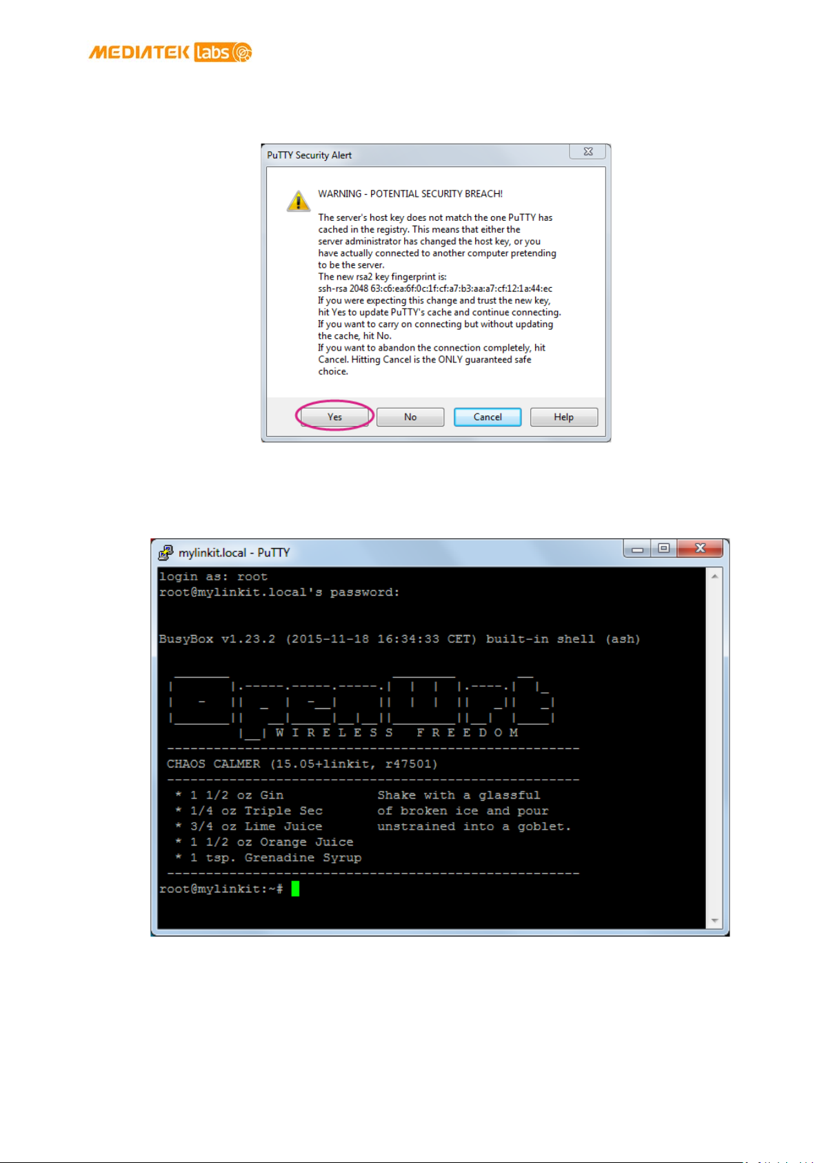
MediaTek LinkIt™ Smart 7688 Developer's Guide
© 2015, 2016 MediaTek Inc.
Page 40 of 100
3) A Security Alert window will pop up as shown in Figure 20 below, this happens when you
use PuTTY for the first time, or after upgrading firmware, or use a different board. Click Yes.
Figure 20 PuTTY Security Warning
4) In the PuTTY terminal window that opens, log in with username root and enter the
password you set previously in the Web UI, after log in you should see a screen similar to
Figure 21.
Figure 21 System Console
• For Mac:
Open Terminal. In the Terminal, type ssh root@mylinkit.local at the command line, hit
return and you’ll be prompted to enter the root password. Enter the password you set
previously in the Web UI.
This document contains information that is proprietary to MediaTek Inc.
Unauthorized reproduction or disclosure of this information in whole or in part is strictly prohibited.

MediaTek LinkIt™ Smart 7688 Developer's Guide
© 2015, 2016 MediaTek Inc.
Page 41 of 100
UART to USB Cable
LinkIt Smart 7688
UART pins
• For Linux:
Open Terminal. In the Terminal, type ssh root@mylinkit.local at the command line, hit
return and log in using the password you set previously.
If you see an error indicating problems with host ID, please refer to FAQ on MediaTek Labs website
For more information on using SSH, please reference
here.
4.5.4.2. Using Serial to USB Cable
You can connect to the system console of LinkIt Smart 7688 by using a Serial (or UART) to USB
cable. First, you need to check if your cable requires driver installation; it may or may not be
needed. Please check the following sections per your OS.
Note: Download the executable version corresponding to your OS from the Currently Supported VCP
Drivers list (FTDI chips only). After installation, the COM port will be successfully identified.
• For Windows:
1) Install driver. If you’re using a USB cable based on FTDI chip please download and install
its driver from
version.
2) Next, you’ll need to connect the Serial to USB cable to LinkIt Smart 7688’s UART pins in
the following table as shown in Table 13:
here. If you’re having problems with the latest driver, try installing an older
RX P8
TX P9
GND GND
Table 13 USB and LinkIt Smart 7688 UART Pin Mapping
This document contains information that is proprietary to MediaTek Inc.
Unauthorized reproduction or disclosure of this information in whole or in part is strictly prohibited.

MediaTek LinkIt™ Smart 7688 Developer's Guide
© 2015, 2016 MediaTek Inc.
Page 42 of 100
3) After you’ve connected the Serial to USB cable, open the device manager and notice the
COM port number as shown in Figure 22. This number may vary on different computers.
Figure 22 LinkIt Smart 7688 COM port using Serial to USB cable
This document contains information that is proprietary to MediaTek Inc.
Unauthorized reproduction or disclosure of this information in whole or in part is strictly prohibited.

MediaTek LinkIt™ Smart 7688 Developer's Guide
© 2015, 2016 MediaTek Inc.
Page 43 of 100
4) Open the PuTTY terminal and enter the COM port number of the USB device found in the
device manager, click on the Serial radio button, type 57600 in Speed box and click Open,
as shown in Figure 23.
Figure 23 Using UART to USB cable to access system console in Windows terminal
5) To exit the system console, click the X on top right of the PuTTY windows.
• For Mac:
1) Install the driver if needed. Check the cable manufacturer’s website for driver
requirements on Mac and installation instructions.
2) Plug-in the cable and connect the cable to LinkIt Smart 7688.
3) Open a Terminal session. You can open it at Applications/Utilities/Terminal.
4) Type ls /dev/cu* in the Terminal. You should see a list of devices. Look for something like
cu.usbserial-XXXXXXXX where XXXXXXXX is usually a random identifier. This is the serial
device used to access the system console. For example:
$ls /dev/cu*
/dev/cu.Bluetooth-Incoming-Port
/dev/cu.Bluetooth-Modem
/dev/cu.pablop-WirelessiAP
/dev/cu.usbserial-A6YMCQBR
5) Use the screen utility to connect to the serial port and set the baudrate to 57600. This is
because the baudrate of the system console is 57600 by default. For example:
$screen /dev/cu.usbserial-XXXXXXXX 57600
This document contains information that is proprietary to MediaTek Inc.
Unauthorized reproduction or disclosure of this information in whole or in part is strictly prohibited.

MediaTek LinkIt™ Smart 7688 Developer's Guide
© 2015, 2016 MediaTek Inc.
Page 44 of 100
6) Now you should be connected to the system console. Press ENTER in the Terminal to
bring up the prompt. You'll notice that the prompt has become different from your OS X
Terminal application, it is the LinkIt Smart 7688 prompt and it looks like the following:
root@myLinkIt:/#
7) You’re ready to make changes to the LinkIt Smart 7688 system through this console.
8) To exit the system console, type <CTRL>a + k, and y.
• For Linux:
1) Install the driver if needed. Check the cable manufacturer’s website for driver
requirements on Ubuntu and installation instructions.
2) Plug-in the cable and connect the cable to LinkIt Smart 7688.
3) Open a Terminal application.
4) Type ls /dev/ttyUSB* in the Terminal. You should see a list of devices. Look for something
like ttyUSB0 where 0 is usually a random identifier. This is the serial device used to access
the system console. For example:
$ls /dev/ttyUSB*
/dev/ttyUSB0
5) Use the screen utility to connect to the serial port and set the baudrate to 57600. This is
because the baudrate of the system console is 57600 by default. One thing to keep in
mind is that in Ubuntu, the serial devices require dialout group permission. Use sudo to
elevate the permission, for example:
$sudo screen /dev/ttyUSB0 57600
6) Now you should be connected to the system console. Press ENTER in the Terminal to
bring up the prompt. You'll notice that the prompt has become different from your Linux
Terminal application, it is the LinkIt Smart 7688 prompt and it looks like the following:
root@myLinkIt:/#
7) You’re ready to make changes to the LinkIt Smart 7688 system through this console.
8) To exit the system console, type <CTRL>a + k, and y.
4.6. System Configuration tasks
This section describes the system configuration task you will need to perform and how to perform
them in the Web UI or system console, or using a USB memory stick.
4.6.1. Upgrading Firmware
This section describes how to upgrade the firmware. You can choose from one of the following
two ways to upgrade firmware on LinkIt Smart 7688:
This document contains information that is proprietary to MediaTek Inc.
Unauthorized reproduction or disclosure of this information in whole or in part is strictly prohibited.

MediaTek LinkIt™ Smart 7688 Developer's Guide
© 2015, 2016 MediaTek Inc.
Page 45 of 100
Note: All user data will be removed from the device after firmware upgrade. The firmware is the same
for both LinkIt Smart 7688 and Duo boards.
• Using Web UI:
1) Sign in the LinkIt Smart 7688 Web UI. Please see section 4.5.3, “Connecting to the Web UI”
if you haven’t signed in before.
2) After you’ve signed in, click on the UPGRADE FIRMWARE as shown in Figure 24.
Figure 24 Firmware upgrade button
3) Click Choose the file and select lks7688.img file. Click UPGRADE & RESTART as shown in
Figure 25.
Figure 25 Selecting firmware file
4) The firmware will upload to LinkIt Smart 7688, please make sure the device stays
connected to its power source until the firmware upgrade is completed.
5) The orange LED will blink for approximately 3 minutes, watch the Wi-Fi LED, it will light
solid to indicate the firmware upgrade has completed and the device will reboot.
This document contains information that is proprietary to MediaTek Inc.
Unauthorized reproduction or disclosure of this information in whole or in part is strictly prohibited.

MediaTek LinkIt™ Smart 7688 Developer's Guide
© 2015, 2016 MediaTek Inc.
Page 46 of 100
Flashing Firmware From a USB Drive
Wi-Fi
Reset
Button
Wi-Fi
LED
Release Wi-Fi Reset Button
When LED Turns Off
Blinks fast (loading)
Auto
Restart
Click
Press
5 secs
Reboot
Release
MPU
Reset
Button
~ 30 secs
Blinks slow (flashing)
~ 3 mins
6) After a few seconds, the Wi-Fi LED turns off. Use the Wi-Fi utility and scan for the
LinkIt_Smart_7688_XXXXXX AP and connect to it. Reload the mylinkit.local webpage.
Set a new password and sign in to see the new firmware version in the software
information as shown in Figure 26.
Figure 26 Firmware version
You now have the latest firmware on your LinkIt Smart 7688 development board.
• Using a USB drive :
The USB drive must be in FAT file system or the file cannot be recognized by the LinkIt
Smart 7688 development platform.
1) Save the firmware file (lks7688.img) in the root directory of a USB drive. You can
download the latest firmware from MediaTek Labs website.
2) Plug the USB drive to LinkIt Smart 7688.
3) Press the Wi-Fi and MPU (Reset) button, then release the MPU Reset button only but hold
the Wi-Fi button for at least 5 seconds and release (Wi-Fi LED turns off), see Figure 27 for
detailed LED status. Do not press the Wi-Fi button for longer than 20s or it will upgrade
the bootloader.
4) LinkIt Smart 7688 will start to read the firmware image (Wi-Fi LED blinks fast) and perform
the firmware upgrade process (Wi-Fi LED blinks slowly). This process takes about 3
minutes to finish.
Unauthorized reproduction or disclosure of this information in whole or in part is strictly prohibited.
This document contains information that is proprietary to MediaTek Inc.
Figure 27 Wi-Fi LED Status During Firmware Upgra

MediaTek LinkIt™ Smart 7688 Developer's Guide
© 2015, 2016 MediaTek Inc.
Page 47 of 100
Warning:
4.6.2. Upgrading bootloader
Do not disconnect the power source or unplug the USB drive during bootloader upgrading
process, or else the data in flash will be damaged and the device will be damaged and fail to boot up
again.
This section describes how to upgrade the bootloader. The USB drive must be in FAT file system or
the file cannot be recognized by the LinkIt Smart 7688 development platform.
Please follow these steps:
1) Save the bootloader file (lks7688.ldr) in the root directory of a USB drive and name it
lks7688.ldr, you can download the latest bootloader from MediaTek Labs website.
2) Plug the USB drive to LinkIt Smart 7688.
3) Press the Wi-Fi and MPU (Reset) button at the same time, then release the MPU Reset
button but hold the Wi-Fi button for at least 20 seconds (after 20s Wi-Fi LED will turn on)
and release.
4) LinkIt Smart 7688 development board will start to read the bootloader (Wi-Fi LED blinks
fast) and perform the bootloader upgrade process (Wi-Fi LED blinks slowly). It takes about
2 seconds to finish the bootloader upgrade process.
4.6.3. Wi-Fi Reset
Press the Wi-Fi Reset button for at least 5 seconds and release. The device will go into AP mode.
4.6.4. Factory Reset
This section describes how to do factory reset on LinkIt Smart 7688 development board. Factory
reset will erase all user data from the board, so proceed with caution. Choose from one of the
following two ways to perform factory reset.
• Using Web UI
Sign in the Web UI, if you need more information refer to section 4.5.3, “Connecting to the
Web UI”, under Factory reset, click RESET, as shown in Figure 28.
Figure 28 Factory Reset using LinkIt Smart 7688 Web UI
• Using the Wi-Fi Reset button
After LinkIt Smart 7688 boots up, press the Wi-Fi Reset button for at least 20 seconds and
release. Please see
development board will reboot to default settings and all user data will be eliminated from the
board, so proceed with caution.
Unauthorized reproduction or disclosure of this information in whole or in part is strictly prohibited.
Figure 1 and Figure 7 for Wi-Fi Reset button locations. LinkIt Smart 7688
This document contains information that is proprietary to MediaTek Inc.

MediaTek LinkIt™ Smart 7688 Developer's Guide
© 2015, 2016 MediaTek Inc.
Page 48 of 100
4.6.5. Connecting LinkIt Smart 7688 to a Wi-Fi Access Point to Access the
internet
This section describes how LinkIt Smart 7688 development board connects to an AP in a Wi-Fi
network to access the internet. To connect to an access point, LinkIt Smart 7688 needs to be in
Station mode. For more information please see section3.4, “Network Environment”.
4.6.5.1. Using the Web UI
Open a browser with URL mylinkit.local. Please see section 4.5.3, “Connecting to the
Web UI” if you’ve not signed in before.
1) Click Network button on upper right as shown in Figure 29.
Figure 29 Change networking setting in Web UI
This document contains information that is proprietary to MediaTek Inc.
Unauthorized reproduction or disclosure of this information in whole or in part is strictly prohibited.

MediaTek LinkIt™ Smart 7688 Developer's Guide
© 2015, 2016 MediaTek Inc.
Page 49 of 100
2) Select the Station mode and click REFRESH or downward arrow on the right to find the AP
to connect to. After you’ve selected the AP, enter password if required. Click CONFIGURE
& RESTART to finish as shown in Figure 30.
Note: If you entered the AP’s password incorrectly, you can reset the board to AP mode by clicking the
Wi-Fi button for at least 5 seconds and restart network setting to Station mode again.
Figure 30 Changing to Station mode in Web UI
3) A message window will pop up letting you know the device is connecting to the AP you’ve
selected and reload the Web UI page to sign in.
4) After you’ve signed in, check the Wi-Fi LED; it should blink once every two seconds, this
indicates LinkIt Smart 7688 is in Station mode.
5) To change LinkIt Smart 7688 back to AP mode, press the Wi-Fi Reset button for at least 5
seconds and release. Please see 4.5.3, “Connecting to the Web UI” for details. Reload the
Web UI and sign in. When you see three short blinks on Wi-Fi LED, it is in AP mode.
You can also use system console to change LinkIt Smart 7688 to AP mode, please see
section 4.6.5.2, “Using the System Console”.
4.6.5.2. Using the System Console
In order for LinkIt Smart 7688 board to access the internet, it needs to join a network that has an
access point connected to the internet, and to do that, the board needs to be in Station mode.
When a LinkIt Smart 7688 development board is in Station mode, it can install software from
OpenWrt to the board using opkg command.
This document contains information that is proprietary to MediaTek Inc.
Unauthorized reproduction or disclosure of this information in whole or in part is strictly prohibited.

MediaTek LinkIt™ Smart 7688 Developer's Guide
© 2015, 2016 MediaTek Inc.
Page 50 of 100
Encryption
UCI Command
string
This section describes how to change LinkIt Smart 7688 to station mode using Unified
Configuration Interface (
1) Make sure the host computer is connected to the AP in a Wi-Fi network.
2) Get the following information from the AP that is in a Wi-Fi network:
o SSID Encryption type, refer to Table 14:
UCI) in the system console.
Open network
WPA-PSK
WPA2-PSK
WEP
none
psk
psk2
not supported
Table 14 Wi-Fi AP Encryption Type
For more information on encryption types please check here.
o Password
3) Open a system console and enter the following commands to change LinkIt Smart 7688
to station mode:
In this example, the following AP is used:
AP SSID: MyAP
Encryption type: WPA2-PSK ( psk2)
Password: 12345678
# uci set wireless.sta.ssid=MyAP
# uci set wireless.sta.encryption=psk2
# uci set wireless.sta.key=12345678
# uci set wireless.sta.disabled=0
# uci commit
# wifi
4) Now check if you’ve established network connection by typing the following command in
the terminal window:
# ping –c 5 www.mediatek.com
This document contains information that is proprietary to MediaTek Inc.
Unauthorized reproduction or disclosure of this information in whole or in part is strictly prohibited.

MediaTek LinkIt™ Smart 7688 Developer's Guide
© 2015, 2016 MediaTek Inc.
Page 51 of 100
If you see a screen similar to Figure 31, congratulations, you’ve connected to the Wi-Fi
network’s AP. The Wi-Fi LED will blink once every two seconds indicating Station mode.
Figure 31 LinkIt Smart 7688 in Station mode connected to a Wi-Fi AP
This document contains information that is proprietary to MediaTek Inc.
Unauthorized reproduction or disclosure of this information in whole or in part is strictly prohibited.

MediaTek LinkIt™ Smart 7688 Developer's Guide
© 2015, 2016 MediaTek Inc.
Page 52 of 100
> ls /Media/USB-A1
> ls /Media/SD-P1
4.6.6. Viewing System Information from the Web UI
You can view LinkIt Smart 7688’s system information from any browser. After you’ve connected
the LinkIt Smart 7688 to a network, open a browser and type http://mylinkit.local
and sign in, click the
will display, as shown in
Configure button under System information and the following information
Figure 32:
• Device name
• Current IP address
• Account
• Password
in the URL box
4.6.7. Accessing the USB drive and the SD Card
When a USB drive or SD card is inserted into LinkIt Smart 7688, they can be accessed under
/Media/SD* or /Media/USB* (The device name displayed varies depending on the number of
drives you use and the number of partitions available on the USB drive or SD card).
You can use the following commands to check the contents of the USB drive and SD card:
• In this example, a USB drive named USB-A1 is used:
• In this example, a SD card named SD-P1 is used:
Unauthorized reproduction or disclosure of this information in whole or in part is strictly prohibited.
Figure 32 System Information in LinkIt Smart 7688 Web
This document contains information that is proprietary to MediaTek Inc.

MediaTek LinkIt™ Smart 7688 Developer's Guide
© 2015, 2016 MediaTek Inc.
Page 53 of 100
File Transfer Service
Protocol
Host
Platform
Tool
4.7. File Editor and Transfer
As a developer, you want freedom to use any text editor of your choice for coding. You can launch
the built-in vim editor in system console to edit source code files directly in LinkIt Smart 7688 or
you can use other editor from a remote computer, but during development, including tasks such
as program execution, it’s common to transfer files between LinkIt Smart 7688 and the remote
programming computer to finish the job. The default system image of LinkIt Smart 7688 provides
several tools for transferring files over Wi-Fi connection. Table 15 shows the types of file transfer
tools:
SCP (Secure Copy) SCP
Windows
OS X scp command
WinSCP
Linux scp command
Samba SMB/CIFS Windows File Explorer built-in
support
OS X Finder built-in support
Linux smbclient
Table 15 File Transfer Tools
4.7.1. Using SCP to copy files in Windows:
SCP tool is one of the most reliable ways to transfer files through the SCP protocol. You can
download tools that support SCP protocol.
command line interfaces:
a) To use GUI, start WinSCP and click Yes when you see a warning window as shown in
Figure 33.
WinSCP is used in this guide. It provides both GUI and
Figure 33 SCP Security Warning
This document contains information that is proprietary to MediaTek Inc.
Unauthorized reproduction or disclosure of this information in whole or in part is strictly prohibited.
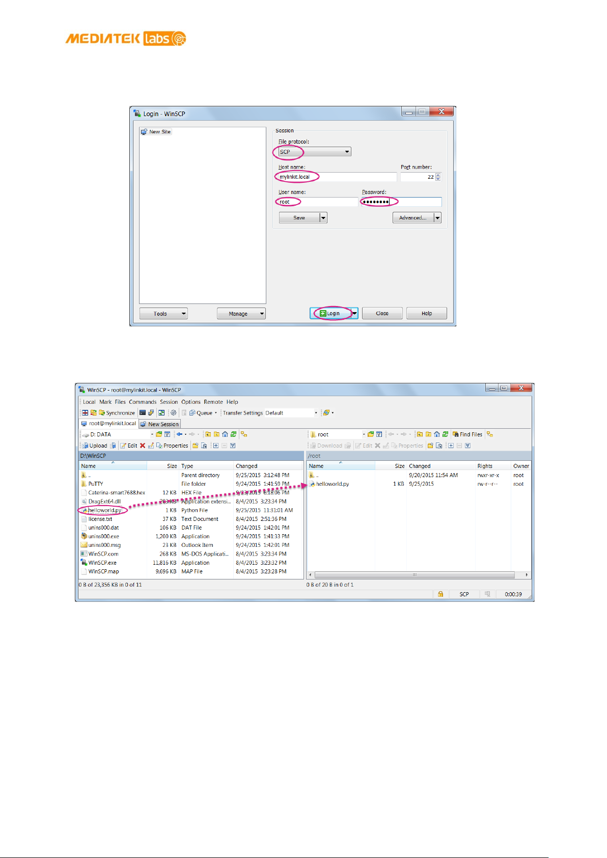
MediaTek LinkIt™ Smart 7688 Developer's Guide
© 2015, 2016 MediaTek Inc.
Page 54 of 100
b) Select SCP for file protocol, enter mylinkit.local in the host name box, root for user
name and password you set in Web UI. Click Login as show in Figure 34 .
Figure 34 WinSCP login window
c) Locate the file you want to transfer on the left pane (your computer) and drag it to the
right (LinkIt Smart 7688), as shown in Figure 35.
Figure 35 File transfer using WinSCP
This document contains information that is proprietary to MediaTek Inc.
Unauthorized reproduction or disclosure of this information in whole or in part is strictly prohibited.

MediaTek LinkIt™ Smart 7688 Developer's Guide
© 2015, 2016 MediaTek Inc.
Page 55 of 100
d) After you’ve dragged the file, an Upload window will appear as shown in Figure 36
asking you to confirm the upload. Click OK.
Figure 36 File transfer confirmation
Check the LinkIt Smart 7688 system console, the helloworld.py file should be there.
Alternatively you can use command line interface, by typing the following command in the
Windows command line console:
winscp.com –hostkey=”*” scp://root@myLinkt.local helloworld.py
Note that by default it requires user to explicitly designate the host key of remote server, so we
need to explicitly allow unknown host key by adding the
-hostkey=”*” parameter.
4.7.2. Using SCP to copy files in OS X
In OS X, SCP command line tool should be already installed and ready to use. If it is not installed,
you can use package managers such as
Terminal and issue following command:
scp ./helloworld root@mylinkit.local:/example/helloworld
In the above example, a file named helloworld from the current directory is copied to the path
/example/helloworld in LinkIt Smart 7688. The SCP tool will instruct you to enter the password
of root account, which is setup in section 4.5.1, “System Configuration Tools”.
MacPorts or Homebrew to install it. To use SCP, open the
4.7.3. Setup Samba service in LinkIt Smart 7688
Samba is a file transfer tool that is built-in LinkIt Smart 7688 and provides a shared folder /Media
on the device for file transfer. In the example below you’ll learn how to use UCI command to
change the shared folder to
/IoT and set appropriate access permission for this folder.
1) Change the shared folder path to /IoT. In LinkIt Smart 7688 console, type the following
command:
# uci set samba.media.path=’/IoT’
This document contains information that is proprietary to MediaTek Inc.
Unauthorized reproduction or disclosure of this information in whole or in part is strictly prohibited.

MediaTek LinkIt™ Smart 7688 Developer's Guide
© 2015, 2016 MediaTek Inc.
Page 56 of 100
2) Name the shared folder MySharedFolder, for example:
# uci set samba.media.name='MySharedFolder'
3) Change the permission of the shared folder to make it readable and writable, for example:
# chmod o+rwx /IoT
4) Save and reboot the LinkIt Smart 7688 platform, for example:
# uci commit
# reboot
5) After LinkIt Smart 7688 reboots and is connected to the same local network as your
computer, you are ready to use the Samba transfer tool. Check the steps according to your
operating system below.
4.7.4. Use Samba to copy files in Windows
Open file explorer and type \\mylinkit.local, you should see the MySharedFolder. Open
another file explorer, drag and drop your file to MySharedFolder, as shown in Figure 37.
Figure 37 File transfer using Samba in Windows
(The remainder of this page is intentionally left blank)
Unauthorized reproduction or disclosure of this information in whole or in part is strictly prohibited.
This document contains information that is proprietary to MediaTek Inc.

MediaTek LinkIt™ Smart 7688 Developer's Guide
© 2015, 2016 MediaTek Inc.
Page 57 of 100
4.7.5. Use Samba to copy files in OS X
The steps to transfer files using Samba in Mac are as follows:
1) Open Finder and in the top menu click Go > Connect to server as shown in Figure 38.
Figure 38 Connecting to LinkIt Smart 7688 from Finder
2) In the server address field, type smb://mylinkit.local and click Connect, as shown in Figure
39.
Figure 39 Connecting to mylinkit.local server in Mac
This document contains information that is proprietary to MediaTek Inc.
Unauthorized reproduction or disclosure of this information in whole or in part is strictly prohibited.

MediaTek LinkIt™ Smart 7688 Developer's Guide
© 2015, 2016 MediaTek Inc.
Page 58 of 100
3) Connect as guest, as shown in Figure 40.
Figure 40 Connecting as guest to mylinkit.local on Mac
4) Check Finder and you’ll see MySharedFoloder as shown in Figure 41. You can now transfer
files in this folder.
Figure 41 MyShareFolder in Mac Finder
(The remainder of this page is intentionally left blank)
This document contains information that is proprietary to MediaTek Inc.
Unauthorized reproduction or disclosure of this information in whole or in part is strictly prohibited.

MediaTek LinkIt™ Smart 7688 Developer's Guide
© 2015, 2016 MediaTek Inc.
Page 59 of 100
5. Peripheral Programming on LinkIt Smart 7688
This chapter describes how to program the peripheral sensors on the LinkIt Smart 7688 board.
From the hardware aspect, MediaTek MT7688AN SOC on the LinkIt Smart 7688 board handles all
the Wi-Fi communication, USB device control, SD card access and sensor connection. As shown in
Figure 42. Related software stacks are provided for developers to access the sensors attached to
the MT7688AN.
UPM is the repository for sensor drivers written in libmraa and it provides API bindings for Python,
Node.js and C languages. So it’s convenient for developers to use UPM to access peripheral
sensors and modules with the programming language that they preferred. LinkIt Smart 7688 has
built-in UPM support. The detailed support list of sensors in UPM can be found in the
page.
UPM project
Figure 42 LinkIt Smart 7688 Software Architecture
5.1. How to Access LinkIt Smart 7688 Peripheral using MRAA
Libmraa is a C/C++ library to interface with the peripheral on LinkIt Smart 7688. Libmraa is preinstalled in the system image of LinkIt Smart 7688 and supports Python, Javascript and Node.js
languages. This section describes how to control LinkIt Smart 7688 peripherals such as GPIO
through libmraa.
5.1.1. Installing MRAA
Libmraa is already installed in the system image of LinkIt Smart 7688, so you don't need to install
it again. However if you want to update the library, or want to port or upgrade the library, please
refer to
libmraa for more information.
This document contains information that is proprietary to MediaTek Inc.
Unauthorized reproduction or disclosure of this information in whole or in part is strictly prohibited.

MediaTek LinkIt™ Smart 7688 Developer's Guide
© 2015, 2016 MediaTek Inc.
Page 60 of 100
GPIO
Pin mapping
To use libmraa in Python, you need to import it. In the below example, libmraa is imported and the
output is the build version of the mraa:
import mraa
print (mraa.getVersion())
For a list of libmraa APIs, please see here for more information.
5.1.2. Basic concepts of libmraa
The majority of hardware modules such as GPIO, UART, SPI, and PWM are represented as objects
created by mraa's factory function. These modules are initialized on certain pins that are
identified by pin numbers. The pin numbers in the libmraa on LinkIt Smart 7688 are identical to the
GPIO number in the data sheet and in the Linux GPIO subsystem.
The following example creates GPIO object on GPIO 2, which maps to P10 of LinkIt Smart 7688 and
it’s the IS2_WS pin in data sheet, as shown in Table 16. Refer to the Pin-out diagram of LinkIt Smart
7688 to see the mapping between the silk print on the board and the GPIO number. This number
also applies to Linux: /sys/class/gpio/2 which maps to exactly the same P10 pin on the LinkIt
Smart 7688 board.
LinkIt Smart 7688 P10
Datasheet IS2_WS
Table 16 LinkIt Smart 7688 GPIO Pin Mapping
import mraa
pin = mraa.Gpio(2) # Initialize GPIO2 (P10 on LinkIt Smart 7688 board)
5.1.3. Libmraa Main Functions
This section introduces major modules of libmraa to give you ideas about how to work with GPIOs
and the other interfaces that are available on LinkIt Smart 7688.
• GPIO and Interrupts
To control GPIO pins, initialize the pin as GPIO pin and set its mode. The simplest operation
mode is
to form signal patterns.
import mraa
pin = mraa.Gpio(2) # Initialize GPIO2 (P10 on LinkIt Smart 7688 board)
pin.dir(mraa.DIR_OUT) # set as OUTPUT pin
OUTPUT - set the pin to HIGH or LOW to enable and disable external switches or
Unauthorized reproduction or disclosure of this information in whole or in part is strictly prohibited.
This document contains information that is proprietary to MediaTek Inc.

MediaTek LinkIt™ Smart 7688 Developer's Guide
© 2015, 2016 MediaTek Inc.
Page 61 of 100
Then, call pin.write(0) to set the pin state to LOW or call pin.write(1) to set the pin
state to
and execute the following code:
import mraa
import time
# Refer to the pinout digram for the GPIO number to silk print mapping
# in this example the number 44 maps to Wi-Fi LED.
pin = mraa.Gpio(44)
pin.dir(mraa.DIR_OUT)
while True:
pin.write(1)
time.sleep(1)
pin.write(0)
time.sleep(1)
There’s another GPIO mode which is INPUT. It takes the digital signal input from the pin
and interprets it into 1 and 0. This example will continuously print out the value received
from P10 on the board. You can short 3V3 and P10 to observe the change in values.
HIGH. To make the Wi-Fi LED blink periodically, set pin 44 (WLED_N) to GPIO mode
import mraa
import time
# Refer to the pinout digram for the GPIO number to silk print mapping
# in this example the number 2 maps to P10 on LinkIt Smart 7688 board
pin = mraa.Gpio(2)
pin.dir(mraa.DIR_IN)
while True:
print "P10 state:", pin.read()
time.sleep(0.3)
Finally, an interrupt service routine can be installed to the pin and invoked when the
values of the input pin P10 (GPIO2) has changed. Call isr API with the trigger type you
want to register and the function to be called. Note that the function runs in a different
thread.
import mraa
import time
def callback(userdata):
print "interrupt triggered with userdata=", userdata
pin = mraa.Gpio(2)
pin.dir(mraa.DIR_IN)
pin.isr(mraa.EDGE_BOTH, callback, None)
while(True):
time.sleep(1)
# simply wait for interrupt
This document contains information that is proprietary to MediaTek Inc.
Unauthorized reproduction or disclosure of this information in whole or in part is strictly prohibited.

MediaTek LinkIt™ Smart 7688 Developer's Guide
© 2015, 2016 MediaTek Inc.
Page 62 of 100
• PWM
Use PWM module to generate a pulse width modulated signal pattern. This is useful to
control actuator peripherals such as servo motors. To use PWM, initialize it on a certain pin
such as GPIO. Note that only GPIO18, GPIO19, GPIO20, GPIO21 supports PWM on LinkIt
Smart 7688. To control the PWM pattern, several parameters are required, including:
o Period
This defines the carrier frequency of the modulation. It’s controlled
by period, period_ms and period_us APIs.
o Duty Cycle or Pulse Width
These two parameters are related to each other and usually you only need to set one
of them. Duty cycle is controlled by write API with a value range between 0.0 to 1.0,
where 0.0 is 0% of duty cycle and 1.0 is 100% of duty cycle. Pulse width also defines
the pattern in a different unit: the "uptime" of the signal in time units. This is defined
by pulsewidth, pulsewidth_ms, and pulsewidth_us APIs.
The following example generates a 500Hz PWM signal with 25% duty cycle on
pin P26.
import mraa
pin = mraa.Pwm(18) # initialize on GPIO18 (pin P26)
pin.period_ms(2) # set PWM frequency to 500Hz (2ms period)
pin.enable(True) # enable PWM output
pin.write(0.25) # set duty cycle to 25%
• I2C
I2C (Inter-Integrated Circuit) is a widely used protocol among peripherals. It consists of 2
signal pins - usually named SDA and SCL. LinkIt Smart 7688 comes with 1 set of I2C
on GPIO4(P21) and GPIO5(P20) as SCL and SDA respectively.
The way I2Cs are initialized is slightly different from GPIO modules - instead of using pins,
I2Cs are initialized according to its device index. Since there is only 1 set of I2C master
device on LinkIt Smart 7688, you can simply pass 0 - and it is always on
pin GPIO4 and GPIO5.
import mraa
i2c = mraa.I2c(0)
Unauthorized reproduction or disclosure of this information in whole or in part is strictly prohibited.
This document contains information that is proprietary to MediaTek Inc.

MediaTek LinkIt™ Smart 7688 Developer's Guide
© 2015, 2016 MediaTek Inc.
Page 63 of 100
I2C is capable of connecting multiple slave devices to a single I2C master. Each slave
device is identified by a 7-bit address. The following example scans for a Seeed Studio 3Axis Digital Accelerometer attached to LinkIt Smart 7688 by reading the device ID from its
registers.
import mraa
i2c = mraa.I2c(0)
# Grove - 3-Axis Digital Accelerometer(+-16g)
# is a ADXL345 configured to I2C address 0x53.
i2c.address(0x53)
# The device ID should be
if 0xE5 == i2c.readReg(0x00):
print "Grove - 3-Axis Digital Accelerometer found on I2C Bus"
else:
print "Grove - 3-Axis Digital Accelerometer not found"
For more details on I2C API, please see here.
To drive an I2C device, you need to operate multiple I2C sequences. LinkIt Smart 7688 also
comes with libUPM pre-installed, which is a set of driver repository built upon libmraa.
Please see
here for a driver example of Seeed Studio 3-Axis Digital Accelerometer.
• SPI
SPI (Serial Peripheral Interface) can also be used to control peripheral devices. On LinkIt
Smart 7688 it consists of 4 pins: SPI_MOSI(P22), SPI_MISO(P23), SPI_CLK(P24),
and SPI_CS1(P25).
It’s important to note that the SPI device is also used for communicating with the internal
flash storage on the board. Therefore, developers should access the SPI functionality
through SPI modules only and avoid treating these SPI pins as general GPIO. Otherwise,
the flash storage may work incorrectly.
The SPI module in libmraa is initialized by device index, instead of pin number.
import mraa
spi = mraa.Spi(0)
The SPI protocol allows flexible configurations on signal patterns. Depending on your
peripheral, you may need to configure the pattern with APIs like bitPerWord and mode.
Please see
here for API details.
5.1.4. LED blink example using mraa in LinkIt Smart 7688 GPIO in Python
This example shows you how to use mraa library in Python to make the Wi-Fi LED on LinkIt Smart
7688 blink.
1) In LinkIt Smart 7688 SSH system console, create a directory called app and go to that
directory. For example:
# mkdir app
# cd app
Unauthorized reproduction or disclosure of this information in whole or in part is strictly prohibited.
This document contains information that is proprietary to MediaTek Inc.

MediaTek LinkIt™ Smart 7688 Developer's Guide
© 2015, 2016 MediaTek Inc.
Page 64 of 100
2) In the root@mylinkit:~/app# prompt, create a file named blink.py by entering the
following command.
# vim blink.py
3) Press i to insert the below codes in the editor. For example:
import mraa
import time
# Refer to the pinout digram for the GPIO number to silk print mapping
# in this example the number 44 maps to Wi-Fi LED
led = mraa.Gpio(44)
led.dir(mraa.DIR_OUT) # set direction to output
while True:
led.write(1) # turn on LED
time.sleep(1)
led.write(0) # turn off LED
time.sleep(1)
4) Press Esc key and :wq! to save the blink.py file.
5) Now you’re ready to run this Python application. In the app directory, type following
command to run the app:
# python ./blink.py
The Wi-Fi LED on LinkIt Smart 7688 should blink every second.
Press <Ctrl> C to terminate the Python program.
5.1.5. LED blink example using mraa in LinkIt Smart 7688 GPIO in Node.js
This example shows you how to use mraa library in Node.js to make the Wi-Fi LED on LinkIt Smart
7688 blink.
1) Connect to LinkIt Smart 7688 console using SSH. In the system console, create a directory
called app and then switch into the directory. For example:
# mkdir app
# cd app
2) Use NPM to initialize your file. NPM is a package manager for Node.js and is pre-installed in
LinkIt Smart 7688. You can install it from
here just in case.
# npm init
This document contains information that is proprietary to MediaTek Inc.
Unauthorized reproduction or disclosure of this information in whole or in part is strictly prohibited.

MediaTek LinkIt™ Smart 7688 Developer's Guide
© 2015, 2016 MediaTek Inc.
Page 65 of 100
periodicActivity();
3) After about 10 seconds, you’ll be prompted to enter several inputs such as a name for app,
version and description etc. as shown in Figure 43. This is a setup process for the Node.js
application. For this tutorial, press enter for all questions.
Figure 43 Set up the Node.js application prompt
4) In the root@mylinkit:~/app# prompt, create a file named app.js by entering the following
command.
# vim app.js
5) Press i to insert the below codes in the editor. For example:
var m = require('mraa');
var ledState = true;
var myLed = new m.Gpio(44); // GPIO44 is the Wi-Fi LED
myLed.dir(m.DIR_OUT);
function periodicActivity() {
myLed.write(ledState ? 1 : 0);
ledState = !ledState;
setTimeout(periodicActivity, 1000);
}
Press Esc key and :wq! to save the app.js file.
6) Now you’re ready to run this Node.js application. In the app directory, type following
command to run app.js:
# node app
The W-Fi LED on LinkIt Smart 7688 should blink every second.
Press <Ctrl> C to terminate the program.
Unauthorized reproduction or disclosure of this information in whole or in part is strictly prohibited.
This document contains information that is proprietary to MediaTek Inc.

MediaTek LinkIt™ Smart 7688 Developer's Guide
© 2015, 2016 MediaTek Inc.
Page 66 of 100
time.sleep(0.3)
5.2. How to use UPM to access sensors and peripherals
UPM is an open source sensor and peripheral driver repository based on libmraa APIs. Among the
popular sensor drivers such as I2C accelerometers and many others are available from this
repository.
LinkIt Smart 7688 system image is pre-installed with UPM and you can start programming on
existing sensors immediately – but if the default implementation is not available, you can use
opkg package manager to update the UPM library.
UPM is similar to libmraa in the way that it comes with bindings in C++, Python and Node.js. Let’s
get started with an example where you’ll learn how to use UPM and Python to receive values from
an I2C accelerometer – a Grove 3-Axis Digital Accelerometer (±16g).
1) Connect the Accelerometer to your board. If you have the breakout board, you can attach
it to the I2C grove interface. If not, you can also connect the pins from the accelerometer
to the corresponding pins GND, 3V3, SDA (P20) and SCL (P21) on LinkIt Smart 7688 board.
2) Import pyupm_adxl345 module from the UPM repository in your program, you’ll do this in
the next step. This module is used because the Grove 3-Axis Digital Accelerometer (±16g)
uses the ADXL345 chipset.
3) Create a Python script adxl.py with following content:
import pyupm_adxl345 as adxl
import time
device = adxl.Adxl345(0)
while True:
device.update()
a = device.getAcceleration()
print "(x,y,z)=%5.1f, %5.1f, %5.1f" % (a[0], a[1], a[2])
4) Execute the Python script in system console by typing the following command:
# python adxl.py
You should see the acceleration value printed repeatedly. Try moving the sensor around to see
changes in the values – now you can use the sensor to detect accelerations.
For a list of other available Python modules in UPM repository, check
also comes with a handful of
examples for your reference.
here. The UPM repository
Unauthorized reproduction or disclosure of this information in whole or in part is strictly prohibited.
This document contains information that is proprietary to MediaTek Inc.

MediaTek LinkIt™ Smart 7688 Developer's Guide
© 2015, 2016 MediaTek Inc.
Page 67 of 100
6. Peripheral Programming on LinkIt Smart 7688 Duo
This chapter describes how to program the peripheral sensors connected to the ATmega32U4
microcontroller and how to communicate between the microcontroller and the MT7688AN, as
shown in Figure 44.
A few key things to be aware of include: the majority of peripherals, including sensors with I2C and
SPI interface are connected to the ATmega32U4 microcontroller on LinkIt Smart 7688 Duo and
the microcontroller on LinkIt Smart 7688 Duo is preloaded with bootloader that supports Arduino
IDE programming. Therefore, the following sections will begin with introduction on how to setup
the Arduino IDE, then, describe the basic ideas of communicating between MT7688AN and
ATmega32U4, followed by some examples of different programming models that can be used to
develop the application logic.
Figure 44 LinkIt Smart 7688 Duo Hardware Architecture
6.1. Installing Arduino IDE
LinkIt Smart 7688 Duo’s MCU (ATmega32U4) can be programmed using Arduino IDE 1.6.5 and
Arduino IDE board support package. You can install Arduino IDE 1.6.5 on your computer from
here.
6.2. Installing Board Support Package
Arduino IDE 1.6.5 supports third party board integration using the Board Manager tool. LinkIt
Smart 7688 Duo development board is a plug-in to Arduino IDE and you’ll need to install the board
package so that Arduino supports LinkIt board. Please follow the steps below:
This document contains information that is proprietary to MediaTek Inc.
Unauthorized reproduction or disclosure of this information in whole or in part is strictly prohibited.

MediaTek LinkIt™ Smart 7688 Developer's Guide
© 2015, 2016 MediaTek Inc.
Page 68 of 100
1) In Arduino IDE, on the File menu click Preferences then insert
http://download.labs.mediatek.com/package_mtk_linkit_smart_7688_index.json
to the Additional Boards Manager URLs field as shown Figure 45:
Figure 45 LinkIt Smart 7688 Duo package URL for a custom board installation in Arduino IDE
2) Make sure your computer is connected to the internet.
3) In the Arduino Tools menu point to Board then click Boards Manager as shown in Figure
46.
Figure 46 Arduino IDE Board Manager Menu
This document contains information that is proprietary to MediaTek Inc.
Unauthorized reproduction or disclosure of this information in whole or in part is strictly prohibited.

MediaTek LinkIt™ Smart 7688 Developer's Guide
© 2015, 2016 MediaTek Inc.
Page 69 of 100
Error downloading the LinkIt ONE SDK package
4) LinkIt Smart 7688 Duo board support package starts downloading automatically and it
may take several seconds for the Boards Manager to download the repository.
If there is a downloading error (see below), remove the cached .json file. The location of the cached
.json file is the same as the location of the preferences.txt file. It can be found in the Arduino IDE
under the File menu by clicking Preferences.
5) There should now be a LinkIt Smart Boards appearing in the boards list on the Boards
Manager as shown in Figure 47. Click the “version” button to select the latest and click
Install.
Figure 47 LinkIt Smart 7688 Board Package Menu
This document contains information that is proprietary to MediaTek Inc.
Unauthorized reproduction or disclosure of this information in whole or in part is strictly prohibited.

MediaTek LinkIt™ Smart 7688 Developer's Guide
© 2015, 2016 MediaTek Inc.
Page 70 of 100
Problem downloading the SDK after the cached
file is removed
6) The installation completes, as shown in Figure 48.
Figure 48 LinkIt Smart 7688 Duo board package installed on Arduino IDE
If there is a problem with the LinkIt Smart 7688 Duo board package installation, try installing Arduino
SAM board package first, as shown below. Then retry LinkIt Smart 7688 Duo installation.
.json
7) You now have the LinkIt Smart 7688 Duo installed on Arduino IDE as show in Figure 49.
This document contains information that is proprietary to MediaTek Inc.
Unauthorized reproduction or disclosure of this information in whole or in part is strictly prohibited.
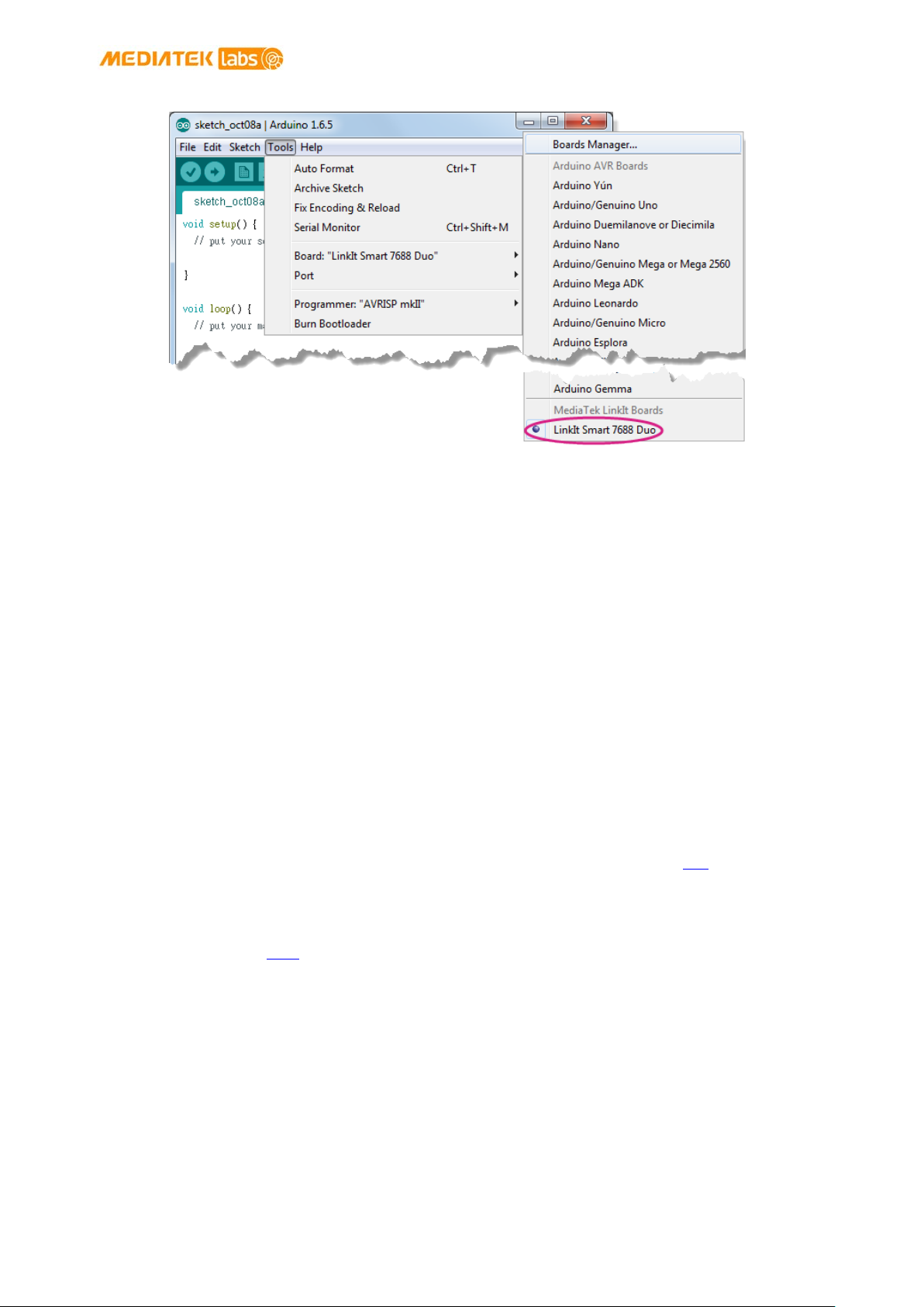
MediaTek LinkIt™ Smart 7688 Developer's Guide
© 2015, 2016 MediaTek Inc.
Page 71 of 100
Figure 49 LinkIt Smart 7688 Duo installed on Arduino IDE
6.3. Installing LinkIt Smart 7688 Duo COM Port Driver
After you’ve installed the board package, connect LinkIt Smart 7688 Duo to your computer and
you should see a USB serial COM port in the device manager with the following port ID:
• Bootloader COM port: VID=0x0E8D, PID=0xAB00
• Arduino Sketch COM port: VID=0x0E8D, PID=0xAB01
Next, you’ll need to install drivers depending on your operating system. The steps are:
• For Windows 10, there is no need to install a driver. However, extra steps are needed to
ensure Windows 10 recognizes the board. Connect LinkIt Smart 7688 Duo to your Windows
10 machine, then quickly press the MCU reset button
system should now recognize LinkIt Smart 7688 Duo as a USB Serial Device (COM5).
The number 5 may be different on different machines. You only need to do this during the
st
1
time connecting the board to your Windows machine.
• For Windows 8, the system may block the driver installation. Follow this link to find out
how to disable driver signature enforcement on Windows 8. After the signature
enforcement is disabled, follow the steps for Windows 7 below to install the driver.
• For Windows 7, find the Serial COM port INF driver in the following path. You can also
install it from
here.
twice within 700 milliseconds. The
This document contains information that is proprietary to MediaTek Inc.
Unauthorized reproduction or disclosure of this information in whole or in part is strictly prohibited.

MediaTek LinkIt™ Smart 7688 Developer's Guide
© 2015, 2016 MediaTek Inc.
Page 72 of 100
{ARDUINO_IDE_PREFERENCE_LOCATION}Arduino15/packages/LinkIt/hardware/avr/0.1
.5/driver/linkit_smart_7688.inf
You’ll find the Arduino preference location at File > Preferences, see the preference.txt
path as shown in Figure 50.
Figure 50 Arduino Preference Location
Right click on the linkit_smart_7688.inf and select install, a security windows appears and click
Install this driver software anyway. As shown in Figure 51. This completes the driver installation.
Figure 51 Driver installation
• For Ubuntu Linux, it should work without installing a driver. LinkIt Smart 7688 Duo should
be in /dev folder and mounted as ttyUSB0. The number 0 may be different on each
Ubuntu machine.
• For OS X, it’s also not required to install a driver, LinkIt Smart 7688 Duo is mounted as a
serial device under/dev/tty.usbmodem1413. The number
OS X machine.
1413 may be different on each
6.4. Programming model for LinkIt Smart 7688 Duo
On LinkIt Smart 7688 Duo, MT7688AN is in charge of the Wi-Fi communication, USB device control
and SD card access. As for sensor and peripheral module connections, ATmega32U4 is used for
This document contains information that is proprietary to MediaTek Inc.
Unauthorized reproduction or disclosure of this information in whole or in part is strictly prohibited.
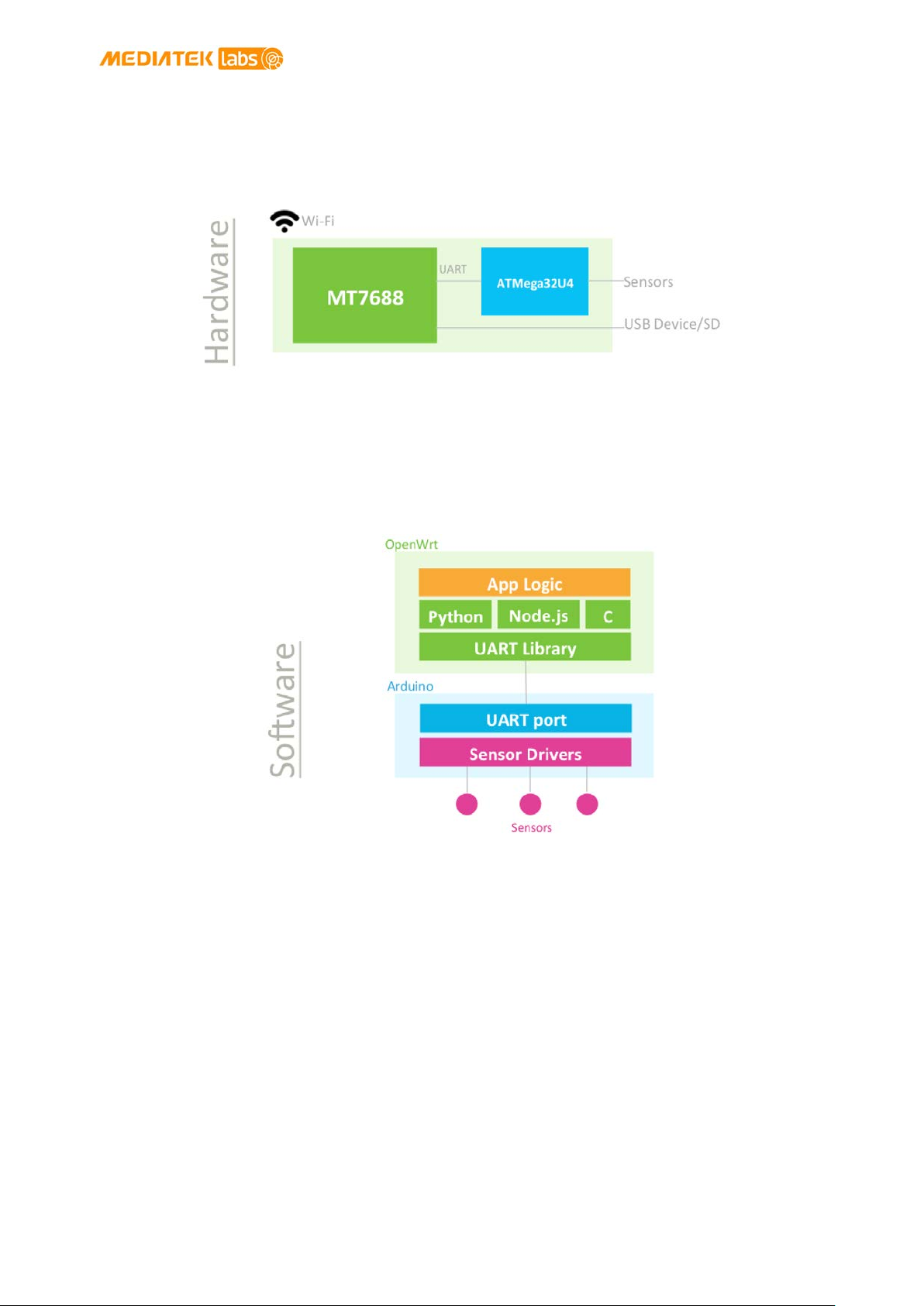
MediaTek LinkIt™ Smart 7688 Developer's Guide
© 2015, 2016 MediaTek Inc.
Page 73 of 100
better responsiveness in real-time control. The programming model used for MCU control is by
Arduino programming through Arduino IDE, as shown in Figure 52. Depending on different
applications and approaches in programming, three scenarios are listed for your reference for
building your software system.
Figure 52 Smart 7688 Duo Hardware Architecture
Scenario #1: Through primitive UART connection
Since MT7688AN and ATmega32U4 are connected through a UART port, you can issue commands
from the application written in Python, Node.js, or C through the UART channel to the MCU side, as
shown in Figure 53. On the MCU side, you implement the codes to interpret commands from MPU
and perform corresponding actions by accessing sensor drivers.
Figure 53 Software architecture
Scenario #2: Through Firmata protocol
In the above scenario #1, you’ll need to implement the commands on the UART channel; this
provides the most general, flexible and powerful way to realize the interaction between MPU and
MCU. However, this also means you need to do the programming on both MPU and MCU side,
which might increase the complexity for the software development.
This document contains information that is proprietary to MediaTek Inc.
Unauthorized reproduction or disclosure of this information in whole or in part is strictly prohibited.

MediaTek LinkIt™ Smart 7688 Developer's Guide
© 2015, 2016 MediaTek Inc.
Page 74 of 100
In order to reduce the complexity of the UART command implementation, Firmata protocol is
proposed as a solution. Firmata is a communication protocol between a MCU and a MPU and many
Firmata implementations has been used to date. Therefore, those whom are familiar with MPU
programming in Python, Node.js and C can choose a language they prefer to use Firmata to run
the MPU and the MCU communication without having to deal with details of the UART command
implementation and MCU side programming, as shown in Figure 54. For example,
popular Node.js framework for Robotics application. It uses Firmata to implement the
communication between MPU and MCU and thus alleviates Node.js developers from low level
UART and MCU programming.
Cylon.js is a
Figure 54 Firmata Protocol
Scenario #3: Through Arduino Yun Bridge Library
For Arduino Yun developers, the MPU Linux side acts as a black box for simply providing Wi-Fi
connectivity and USB / SD peripheral accessibility. LinkIt Smart 7688 Duo also provides Arduino
Yun Bridge library implementation for developers to build their projects the way they are familiar
with, as shown in Figure 55. This gives developers not only a familiar way to do development but
also access to a more stable, powerful and energy efficient platform that MT7688AN can deliver.
Figure 55 Yun Bridge Library
This document contains information that is proprietary to MediaTek Inc.
Unauthorized reproduction or disclosure of this information in whole or in part is strictly prohibited.

MediaTek LinkIt™ Smart 7688 Developer's Guide
© 2015, 2016 MediaTek Inc.
Page 75 of 100
MCU
MPU
}
6.5. Programming with Primitive UART Connection
In all the scenarios described in previous section, the MPU and MCU on LinkIt Smart 7688 Duo
communicates using Serial port. The MCU communicates with OpenWrt Linux over UART
hardware. Table 17 illustrates the communication between MCU and MPU:
In Arduino
Corresponding Pins
Serial1
D0 and D1
In Linux
Pin MUX
/dev/ttyS0
UART0 (GPIO12 and
GPIO13)
Table 17 MCU and MPU Communication
In the following section an example is provided to demonstrate how to communicate between the
MCU and MPU side by writing to and reading from the primitive UART connection.
6.5.1. Blink Program - Arduino Side
The MCU side is written as an Arduino sketch. In this example, the sketch simply listens to the
command sent from the MPU (Linux) side and switches the on-board LED accordingly.
1) First, connect the LinkIt Smart 7688 Duo to your PC, then open Arduino IDE and paste the
following sketch code into the IDE:
void setup() {
Serial.begin(115200); // open serial connection to USB Serial port
(connected to your computer)
Serial1.begin(57600); // open internal serial connection to MT7688AN
// in MT7688AN, this maps to device
pinMode(13, OUTPUT);
}
void loop() {
int c = Serial1.read(); // read from MT7688AN
if (c != -1) {
switch(c) {
case '0': // turn off D13 when receiving "0"
digitalWrite(13, 0);
break;
case '1': // turn off D13 when receiving "1"
digitalWrite(13, 1);
break;
}
}
2) Then choose the correct COM port from the IDE (check your device manager) by clicking
Tools > Port.
This document contains information that is proprietary to MediaTek Inc.
Unauthorized reproduction or disclosure of this information in whole or in part is strictly prohibited.

MediaTek LinkIt™ Smart 7688 Developer's Guide
© 2015, 2016 MediaTek Inc.
Page 76 of 100
3) Upload the sketch to the board as shown in Figure 56. Note the board is not blinking yet –
you’ll need to write a program in the Linux side to make it blink, which is the next step.
Figure 56 Upload Sketch in Arduino IDE
6.5.2. Blink Program – Linux Side
As describe in chapter 3.3, “Programming Model for Different Boards”, you can program the Linux
side using many languages, including C/C++, Python or Node.js. In this example, Python is used to
illustrate a program that sends command to the MCU (Arduino) side to make the LED blink.
This document contains information that is proprietary to MediaTek Inc.
Unauthorized reproduction or disclosure of this information in whole or in part is strictly prohibited.

MediaTek LinkIt™ Smart 7688 Developer's Guide
© 2015, 2016 MediaTek Inc.
Page 77 of 100
loop()
1) Use a text editor of your choice and create a new file, then copy the following code and
save it.
import serial
import time
s = None
def setup():
global s
# open serial COM port to /dev/ttyS0, which maps to UART0(D0/D1)
# the baudrate is set to 57600 and should be the same as the one
# specified in the Arduino sketch uploaded to ATmega32U4.
s = serial.Serial("/dev/ttyS0", 57600)
def loop():
# send "1" to the Arduino sketch on ATmega32U4.
# the sketch will turn on the LED attached to D13 on the board
s.write("1")
time.sleep(1)
# send "0" to the sketch to turn off the LED
s.write("0")
time.sleep(1)
if __name__ == '__main__':
setup()
while True:
2) Execute this Python program in the system console – this program basically writes string
“1” and “0” to the /dev/ttyS0 port which maps to Serial1 interface in Arduino. The Arduino
sketch that was uploaded in the previous section will receive the string and then blink the
on-board LED accordingly.
You can now extend the Arduino sketch to drive other devices such as PWM, I2C devices and
synchronize the states by extending the command messages between Arduino and the Linux side.
If a large amount of peripheral types need to be included, you may want to use some external
libraries to implement the communication protocol. One of such protocol – Firmata is described
in the following section.
6.6. Programming with Firmata Protocol
This section demonstrates how to establish communication between the MPU and the MCU over
serial port using Firmata protocol. There are several Firmata implementations using different
interfaces such as pyFirmata and PyMata, which is programmed in Python; other languages
including Node.js and cylon.js examples are provided as well in the next sections.
6.6.1. Python examples
This document contains information that is proprietary to MediaTek Inc.
Unauthorized reproduction or disclosure of this information in whole or in part is strictly prohibited.

MediaTek LinkIt™ Smart 7688 Developer's Guide
© 2015, 2016 MediaTek Inc.
Page 78 of 100
MCU
MPU
Two examples are provided in Python in the following sections to demonstrate how to use the
Firmata protocol: pyFirmata and PyMata interfaces.
The Serial ports on the microcontrollers are designated as shown in Table 18:
In Arduino
Corresponding Pins
Serial1
D0 and D1
In Linux
Pin MUX
/dev/ttyS0
UART0 (GPIO12 and
GPIO13)
Table 18 Serial Pin Mapping Between MPU and MCU
6.6.2. Prototype
The diagram, as shown in Figure 57, illustrates how the MPU and MCU in LinkIt Smart 7688 Duo
communicate with each other using Firmata protocol and Python.
Figure 57 MPU MCU Communication Diagram
6.6.3. Setup Your Development Environment
LinkIt Smart 7688 Duo supports Arduino 1.6.5 and Python 2.7.
Firmata protocol requires implementation on the MPU and the MCU. To begin, you’ll need to
install software to program the MCU.
Please make sure you’ve installed the following:
• For your PC:
o Arduino IDE 1.6.5
It provides a set of default implementations and programs the ATmega32U4.
This document contains information that is proprietary to MediaTek Inc.
Unauthorized reproduction or disclosure of this information in whole or in part is strictly prohibited.

MediaTek LinkIt™ Smart 7688 Developer's Guide
© 2015, 2016 MediaTek Inc.
Page 79 of 100
• For your LinkIt Smart 7688 Duo :
o Python 2.7
It’s preloaded in the system image.
o pyFirmata
This is a Python interface for Firmata protocol used on the MCU. You can install it by
typing pip install pyfirmata in the system console. At the time of writing, LinkIt Smart
7688 Duo supports version
o PyMata
This is a Python interface for the Firmata protocol used on the MPU. You can install it
by typing pip install PyMata in the console. At the time of writing, LinkIt Smart 7688
Duo supports version
Note: The LinkIt Smart 7688 Duo needs to be in Station mode in order to use pip to install the
pyFirmata and PyMata interface, please see section 3.4.2, “Station Mode” for details on how to set
station mode.
pyFirmata-1.0.3-py2.7.
pymata-2.1.
6.6.4. PyFirmata Approach
• Uploading The Arduino Firmata Sketch
This section describes setting up Arduino to listen for Firmata commands from the Serial
port.
1) Open the
2) In Arduino IDE, open the example File > Examples > Firmata > StandardFirmata
Firmata.begin(57600);
3) And change it to:
Serial1.begin(57600);
Firmata.begin(Serial1);
Arduino IDE 1.6.5
This built-in example is for Arduino Uno, which uses Serial as Serial port.
However, LinkIt Smart 7688 Duo uses Serial1 to communicate with OpenWrt.
Therefore, you’ll need to change the listening port of this example from
Serial to Serial1.Find the following line in the example:
4) Upload the sketch. After uploading the sketch, Arduino is ready to receive commands
from the Linux side.
• Running Your Blink Example Using pyFirmata
After pyFirmata is installed, you’re ready to run a blink example.
1) In the console, create a python file called blink_with_firmata.py
Unauthorized reproduction or disclosure of this information in whole or in part is strictly prohibited.
This document contains information that is proprietary to MediaTek Inc.

MediaTek LinkIt™ Smart 7688 Developer's Guide
© 2015, 2016 MediaTek Inc.
Page 80 of 100
board.digital[13].write(1)
sleep(0.5)
board.digital[13].write(0)
2) Open the file and copy and paste the following example code. This example code is
modified to work for LinkIt Smart 7688 Duo. For example:
from pyfirmata import Arduino, util
from time import sleep
board = Arduino('/dev/ttyS0')
print "Start blinking D13"
while True:
sleep(0.5)
3) Now execute this Python script and you should see following message:
# python ./blink_with_firmata.py
Start blinking D13
If you see the LED on D13 of the LinkIt Smart 7688 Duo blink accordingly, congratulations. You’ve
successfully ran the blink example.
To terminate the Python program, press Ctrl-C.
6.6.5. PyMata Approach
• Uploading the Arduino PyMata Sketch
PyMata is a Python interface for the Firmata protocol and it uses its own Firmata sketch.
Therefore you need to install the PyMata libraries before you start uploading the sketch to
Arduino.
Please make sure you’ve the following:
1) Download
computer and extract it.
2) In the extracted folder, open the folder ArduinoSketch and you should see the
library.zip file.
3) Extract the content of the library.zip file.
4) Copy the extracted content of the library.zip file to your Arduino Library folder
C:\Program Files (x86)\Arduino\libraries\
PyMata libraries (PyMata-master.zip) to Arduino library folder on your
This document contains information that is proprietary to MediaTek Inc.
Unauthorized reproduction or disclosure of this information in whole or in part is strictly prohibited.

MediaTek LinkIt™ Smart 7688 Developer's Guide
© 2015, 2016 MediaTek Inc.
Page 81 of 100
• Using FirmataPlus Example
Now you’re ready to set up Arduino to listen for Firmata commands from the Serial port.
1) Open the Arduino IDE 1.6.4 or 1.6.5
2) In Arduino IDE, open the example File > Examples > FirmataPlus > FirmataPlus
This built-in example is for Arduino Uno, which uses Serial as Serial port.
However, LinkIt Smart 7688 Duo uses Serial1 to communicate with OpenWrt.
Therefore, you’ll need to change the listening port of this example from
Serial to Serial1. Find the following line in the example:
Firmata.begin(57600);
3) And change it to
Serial1.begin(57600);
Firmata.begin(Serial1);
4) Upload the sketch. After uploading the sketch, Arduino is ready to receive commands
from the Linux side.
• Running Blink Example Using PyMata
After you’ve installed PyMata libraries and changed the serial port in Arduino, you’re ready
to run the blink example using PyMata.
1) Download
You’ll also need to change the serial port used in this example to work on LinkIt Smart
7688 Duo. Find the following line on the example:
# Create a PyMata instance
board = PyMata("/dev/ttyACM0", verbose=True)
2) And change it to:
# Create a PyMata instance
board = PyMata("/dev/ttyS0", verbose=True)
blink example to LinkIt Smart 7688 Duo.
This document contains information that is proprietary to MediaTek Inc.
Unauthorized reproduction or disclosure of this information in whole or in part is strictly prohibited.

MediaTek LinkIt™ Smart 7688 Developer's Guide
© 2015, 2016 MediaTek Inc.
Page 82 of 100
3) Exeute the python script and you should see following output:
# python ./pymata_blink.py
Python Version 2.7.9 (default, Aug 12 2015, 15:09:09)
[GCC 4.8.3]
PyMata version 2.10 Copyright(C) 2013-15 Alan Yorinks All rights
reserved.
Opening Arduino Serial port /dev/ttyS0
Please wait while Arduino is being detected. This can take up to 30 seconds
...
Board initialized in 0 seconds
Total Number of Pins Detected = 30
Total Number of Analog Pins Detected = 12
Blinking LED on pin 13 for 10 times ...
1
2
3
4
5
6
7
8
9
10
PyMata close(): Calling sys.exit(0): Hope to see you soon!
If you see the LED on D13 of the LinkIt Smart 7688 Duo blink 10 times before the Python program
terminates, congratulations. You’ve successfully ran the blink example.
Please continue to explore more examples in the PyMata/examples you’ve downloaded earlier.
Just remember to change the serial port to/dev/ttyS0, and keep in mind the hardware
differences between LinkIt Smart 7688 Duo and Arduino Uno:
• LinkIt Smart 7688 Duo operates in 3.3V, not 5V as in Arduino Uno.
• You’ll need extra power source when driving motor or servo peripherals because they
draw more current.
Please refer to
Firmata website for other Python interfaces available to Firmata protocol.
6.6.6. Node.js example
This section illustrates the MPU and MCU communication using Firmata protocol in Node.js. The
main steps are:
1) Set up the MCU, start by Launching Arduino IDE 1.6.5 on your computer
This document contains information that is proprietary to MediaTek Inc.
Unauthorized reproduction or disclosure of this information in whole or in part is strictly prohibited.

MediaTek LinkIt™ Smart 7688 Developer's Guide
© 2015, 2016 MediaTek Inc.
Page 83 of 100
2) Copy the Firmata example to Arduino, you do this by opening a browser and click here.
You’ll see a Firmata example code. Click on Raw button to copy the code, as shown in
Figure 58 below.
Figure 58Copying example code from Github
3) Copy the example code to the Arduino IDE and click Upload, as shown in Figure 59.
Figure 59 Uploading example sketch in Arduino IDE
This document contains information that is proprietary to MediaTek Inc.
Unauthorized reproduction or disclosure of this information in whole or in part is strictly prohibited.

MediaTek LinkIt™ Smart 7688 Developer's Guide
© 2015, 2016 MediaTek Inc.
Page 84 of 100
$ npm init
$ npm install firmata –-save
$ rm –rf ./node_modules/firmata/node_modules/serialport
$ tar –cvf ./firmata.tar ./node_modules/firmata
$ scp ./firmata.tar root@mylinkit.local:/root/app/node_modules
# vim app.js
4) Set up the MPU, for this you’ll need to install Firmata on your computer. While you can
install Firmata using NPM on LinkIt Smart 7688 Duo, the process is a bit long, that’s why
you should install
there. In your host computer, create a folder called testfirmata and switch to the
directory. The $ indicates command prompt and is not part of the command.
$ mkdir testfirmata && cd testfirmata
5) After you’ve installed NPM, use it to initialize the file. For example:
6) Install Firmata by typing the following command.
NPM on your computer instead and do the Firmata installation from
7) Remove node-serial port by typing the following command.
Firmata has a built in node-serial port and when you installed Firmata, it creates a compile file on
your computer. However, this compile file needs to be removed because it’s already built in LinkIt
Smart 7688 Duo .
8) Compress the Firmata folder
9) Use scp to transfer the compressed file to LinkIt Smart 7688 Duo
10) Open the LinkIt Smart 7688 Duo SSH system console and type the following commands to
create a directory called app and go to that directory.
# mkdir app && cd app
11) Create a file called app.js
This document contains information that is proprietary to MediaTek Inc.
Unauthorized reproduction or disclosure of this information in whole or in part is strictly prohibited.

MediaTek LinkIt™ Smart 7688 Developer's Guide
© 2015, 2016 MediaTek Inc.
Page 85 of 100
# node app
12) Type i to insert the following example code:
console.log('WWW blink start ...');
var ledPin = 13;
var firmata = require('firmata');
var board = new firmata.Board("/dev/ttyS0",function(err) {
if (err) {
console.log(err);
board.reset();
return;
}
console.log('connected...');
console.log('board.firmware: ', board.firmware);
board.pinMode(ledPin, board.MODES.OUTPUT);
var url = require('url');
var http = require('http');
http.createServer(function(request, response) {
var params = url.parse(request.url, true).query;
if (params.value.toLowerCase() == 'high') {
board.digitalWrite(ledPin, board.HIGH);
} else {
board.digitalWrite(ledPin, board.LOW);
}
response.writeHead(200);
response.write("The value written was: " + params.value);
response.end();
}.bind(this)).listen(8080);
console.log('Listening on port 8080 ...');
});
13) Type Esc key and :wq! to save and exit the editor.
14) Run the Node.js example by typing the following command in the system console:
15) Open a browser and enter the following commands to control the LED:
a) To turn LED ON: mylinkit.local:8080?value=high
b) To turn LED OFF: mylinkit.local:8080?value=low
16) The D13 LED on LinkIt Smart 7688 Duo should blink according to your command of choice.
This document contains information that is proprietary to MediaTek Inc.
Unauthorized reproduction or disclosure of this information in whole or in part is strictly prohibited.

MediaTek LinkIt™ Smart 7688 Developer's Guide
© 2015, 2016 MediaTek Inc.
Page 86 of 100
$ npm init
$ tar –cvf ./cylon.tar ./node_modules/cylon
6.6.7. Cylon.js example
This section illustrates the MPU and MCU communication using Firmata in Cylon.js programming
language. The steps are:
1) Set up the MCU, start by launching Arduino IDE 1.6.5 on your computer.
2) Copy the Firmata example, you do this by opening a browser and click
here. You’ll see a
Firmata example code. Click on Raw button to copy the code, similar to Figure 58.
3) Set up the MPU, for this you’ll need to install Firmata and four Cylon modules (cylon,
cylon-firmata, cylon-gpio and cylon-i2c) on your computer. The Cylon modules are
needed to communicate with the hardware attached to Arduino. While you can install
Firmata and Cylon using NPM on LinkIt Smart 7688 Duo, the process is a bit long, that’s
why you should install
NPM on your computer instead and install Firmata and the Cylon
modules from there. The steps to install Firmata are already described in section 6.6.6,
“Node.js example” and it’s the same for Cylon. Therefore, only Cylon example is used
below. Create a folder called testcylon and switch to the directory. The $ indicates
command prompt and is not part of the command.
$ mkdir testcylon && cd testcylon
4) After you’ve installed NPM, use it to initialize the file. For example:
5) Install four Cylon on your computer by typing the following command.
$ npm install cylon –-save
$ npm install cylon-firmata –-save
$ npm install cylon-gpio –-save
$ npm install cylon-i2c –-save
6) Remove node-serial port by typing the following command.
$ rm –rf ./node_modules/cylon/node_modules/serialport
$ rm –rf ./node_modules/cylon-firmata/node_modules/serialport
$ rm –rf ./node_modules/cylon-gpio/node_modules/serialport
$ rm –rf ./node_modules/cylon-i2c/node_modules/serialport
Cylon has a built in node-serial port and when you installed Cylon, it creates a compile file on your
computer. However, this compile file needs to be removed because it’s already built in LinkIt
Smart 7688 Duo.
7) Compress the Cylon folder
This document contains information that is proprietary to MediaTek Inc.
Unauthorized reproduction or disclosure of this information in whole or in part is strictly prohibited.

MediaTek LinkIt™ Smart 7688 Developer's Guide
© 2015, 2016 MediaTek Inc.
Page 87 of 100
$ scp ./cylon.tar root@mylinkit.local:/root/app/node_modules
}).start();
8) Use scp to transfer the compressed file to LinkIt Smart 7688 Duo
9) Set up the MPU, start by opening the SSH console and create a folder app, # is the console
prompt and is not part of the command.
# mkdir app && cd app
10) Create a file app.js and open text editor by typing:
# vim app.js
11) Press i and copy the following example in the text editor:
var Cylon = require('cylon');
Cylon.robot({
connections: {
arduino: { adaptor: 'firmata', port: '/dev/ttyS0' }
},
devices: {
led: { driver: 'led', pin: 13 }
},
work: function(my) {
every((1).second(), my.led.toggle);
}
12) Save and exit the editor by typing Esc key and :wq!
13) Execute the Cylon.js program by typing the following command:
# node app.js
14) The D13 LED on LinkIt Smart 7688 Duo should blink every second.
6.6.8. Updating the ATmega32U4 Bootloader
This chapter explains the methods you can use to program the bootloader on the ATmega32U4.
LinkIt Smart 7688 Duo is pre-programmed with Arduino bootloader in the microcontroller
(ATmega32U4). You are not required to program the bootloader, but in the event the bootloader
is damaged or requires re-programming, you can use one of the following methods to update the
bootloader.
This document contains information that is proprietary to MediaTek Inc.
Unauthorized reproduction or disclosure of this information in whole or in part is strictly prohibited.

MediaTek LinkIt™ Smart 7688 Developer's Guide
© 2015, 2016 MediaTek Inc.
Page 88 of 100
6.6.9. Using LinkIt Smart 7688 Duo to program bootloader on another
LinkIt Smart 7688 Duo
In the following example, there are two LinkIt Smart 7688 Duo boards called A and B. The first
board A will act as the programmer to program the second board B.
1) In Arduino IDE, go to Tools > Board > and select LinkIt Smart 7688 Duo
2) Open the sketch Example > ArduinoISP
3) Modify the code line #define RESET SS to #define RESET 10
4) Upload the modified sketch to board A
5) Connect pins S0, S1, S2, GND of board A to the same pins of board B
6) Connect pin D10 of board A to pin RST of board B
7) In Arduino IDE, go to Tools > Programmer > and select LinkIt Smart 7688 Duo as ISP
8) Finally, go to Tools > and select Burn Bootloader
6.6.9.1. Using AVRDUDE from OpenWrt to Program Bootloader
You can also program ATmega32U4 from the Linux side (MT7688AN). The system image is
preloaded with AVRDUDE package that allows you to program the ATmega32U4. AVRDUDE is a
command line tool for flashing codes to MCU on Linux.
1) opy the bootloader file to a storage device (USB drive or SD card) or to your computer. The
bootloader file is located in the following path:
{ARDUINO_IDE_PREFERENCE_LOCATION}\Arduino15\packages\LinkIt\hardware\avr
\0.1.5\bootloaders\caterina\Caterina-smart7688.hex
Please see Figure 50 for Arduino preference location.
2) Transfer the bootloader to LinkIt Smart 7688 Duo. You can use a storage device or SCP
tool to transfer the bootloader. In this example, a USB drive called USB-A1 is used.
Connect the USB drive to LinkIt Smart 7688 Duo and in the system console, go to the root
directory by typing the following command:
# cd /Media/USB-A1
3) In the system console, execute the following command:
# avrdude –p m32u4 –c linuxgpio –v –e –U flash:w:Caterina-smart7688.hex –U
lock:w:0x0f:m
Unauthorized reproduction or disclosure of this information in whole or in part is strictly prohibited.
This document contains information that is proprietary to MediaTek Inc.

MediaTek LinkIt™ Smart 7688 Developer's Guide
© 2015, 2016 MediaTek Inc.
Page 89 of 100
4) After the bootloader is programmed into the ATmega32U4, you should see a screen
similar to Figure 60.
Figure 60 Programming bootloader using AVRDUDE
5) Please refer to AVRDUDE package for detailed information.
6.7. Programming with Yun Bridge Library
LinkIt Smart 7688 Duo can also facilitate the Yun Bridge library to a certain degree. To make the
Bridge library work, you’ll need to configure the system to allow various Bridge related services to
run. You’ll also need to set the system console to map to /dev/ttyS0 which allows the Arduino
side to issue commands to the Linux system. Luckily, the default system image of LinkIt Smart
7688 Duo wraps all the aforementioned configurations into a single UCI configuration. All you
need to do is to enable it. You can do this by typing the following command in the system console
and reboot the system. For example:
# uci set yunbridge.config.disabled=’0’
# uci commit
# reboot
After reboot finishes, the system is ready to accept commands from the Arduino side. Connect the
board to you computer and open Arduino IDE, then choose
TimeCheck. Next, upload the TimeCheck example sketch to LinkIt Smart 7688 Duo and launch the
Serial Monitor. You should see following outputs from the Serial Monitor.
File > Examples > Bridge >
Time Check
00:00:00
03:42:05
03:42:06
The output time stamp should be the same as the Linux system time stamp.
Unauthorized reproduction or disclosure of this information in whole or in part is strictly prohibited.
This document contains information that is proprietary to MediaTek Inc.

MediaTek LinkIt™ Smart 7688 Developer's Guide
© 2015, 2016 MediaTek Inc.
Page 90 of 100
You can also try other examples of the Bridge library. Note that some scripts and services may act
differently on the default system image, so you may need to modify the sketch files accordingly.
Please also note that while the system is configured to work with the Bridge library, the
/dev/ttyS0 becomes occupied by the Bridge library and it is not advised to try accessing it when
in use. For example, Firmata won’t work when the system is configured to support Bridge library.
To stop the system from launching Bridge related services and occupying /dev/ttyS0, use
following commands in system console and reboot the system:
# uci set yunbridge.config.disabled=’1’
# uci commit
# reboot
Unauthorized reproduction or disclosure of this information in whole or in part is strictly prohibited.
This document contains information that is proprietary to MediaTek Inc.

MediaTek LinkIt™ Smart 7688 Developer's Guide
© 2015, 2016 MediaTek Inc.
Page 91 of 100
7. How to Build Firmware and Bootloader
This chapter explains how to build firmware and bootloader for the LinkIt Smart 7688/7688Duo
development platform.
7.1. Building a firmware
The LinkIt Smart 7688/7688 Duo development platform supports Makefile-based builds, which
allows you to build firmware with the make command.
Instructions in this section apply for an Ubuntu Linux 14.04.3 environment.
1) The first step is to install virtual machine if your host environment isn’t Ubuntu. The disk
space you should reserve is about 50GB
o Get the Ubuntu 14.04.3 LTS from
o Install Virtual Box from
2) Building a firmware requires installing prerequisite packages. Open Terminal and type the
following command:
$ sudo apt-get install git g++ libncurses5-dev subversion libssl-dev gawk
libxml-parser-perl unzip
3) Download the OpenWrt CC source code; it includes the full OpenWrt environment to build
the firmware (including the Linux kernel). Type the following command to download the
source code:
$ git clone git://git.openwrt.org/15.05/openwrt.git
4) Create a configuration file feeds.conf by copying from the default template file
feeds.conf.default
$ cd openwrt
$ cp feeds.conf.default feeds.conf
5) Add the LinkIt Smart 7688 feed to feeds.conf
http://virtualbox.org
http://www.ubuntu.com
$ echo src-git linkit https://github.com/MediaTek-Labs/linkit-smart-7688feed.git >> feeds.conf
6) Update the feed information for all packages needed to build firmware
$ ./scripts/feeds update
7) Install all packages
$ ./scripts/feeds install –a
This document contains information that is proprietary to MediaTek Inc.
Unauthorized reproduction or disclosure of this information in whole or in part is strictly prohibited.

MediaTek LinkIt™ Smart 7688 Developer's Guide
© 2015, 2016 MediaTek Inc.
Page 92 of 100
$ sudo apt-get install libc6:i386 libncurses5:i386 libstdc++6:i386
8) Prepare the kernel configuration file for informing OpenWrt the intention to build a
firmware for LinkIt Smart 7688
$ make menuconfig
9) Select options to set target profile per below:
o Target System: Ralink RT288x/RT3xxx
o Subtarget: MT7688 based boards
o Target Profile: LinkIt 7688
10) Save the options and exit (use the default config file name without changing it)
11) Start the firmware compilation process with make
$ make V=99
12) After the compilation process completes, the resulting firmware file will be under
bin/ramips/openwrt-ramips-mt7688-LinkIt7688-squashfs-sysupgrade.bin
13) Now you can use this file to do the firmware upgrade through Web UI or rename it to
lks7688.img and use it to upgrade firmware through a USB drive.
7.2. Building a bootloader
The LinkIt Smart 7688/7688 Duo development platform supports Makefile-based builds, which
allows you to build bootloader with the make command.
The instructions in this section apply for an Ubuntu Linux 14.04.3 environment.
1) Please refer to section 7.1, “Building a firmware” for preparing the environment for building
bootloader.
2) Download the bootloader source codeby typing the following command:
$ git clone https://github.com/MediaTek-Labs/linkit-smart-uboot.git
3) Change to the LinkIt Smart 7688 bootloader source code folder
$ cd linkit-smart-uboot
4) Install the tool-chain needed for building bootloader, this tool-chain is provided in 32-bit
executable
$ sudo tar xjf buildroot-gcc342.tar.bz2 -C /opt/
5) Install additional packages to execute the tool-chain in a 64-bit machine
$ sudo dpkg --add-architecture i386
$ sudo apt-get update
6) Start the bootloader compilation process
This document contains information that is proprietary to MediaTek Inc.
Unauthorized reproduction or disclosure of this information in whole or in part is strictly prohibited.

MediaTek LinkIt™ Smart 7688 Developer's Guide
© 2015, 2016 MediaTek Inc.
Page 93 of 100
$ make
7) After the compilation process finishes, the resulting bootloader file is uboot.bin
8) Now you can rename this file to lks7688.ldr and use it to upgrade bootloader through a
USB drive.
(The remainder of this page is intentionally left blank)
This document contains information that is proprietary to MediaTek Inc.
Unauthorized reproduction or disclosure of this information in whole or in part is strictly prohibited.

MediaTek LinkIt™ Smart 7688 Developer's Guide
© 2015, 2016 MediaTek Inc.
Page 94 of 100
8. Troubleshooting Guide
8.1. My firmware upgrade won’t start or failed. Why?
If you’re using a USB drive to upgrade firmware, please make sure you’ve checked the following:
• The USB host cable that connects to the USB drive is firmly attached
• The USB power/host cable is securely attached to the Power connector and not the Host
connector of the board.
If you’re using the Web UI to upgrade firmware, please make sure you’ve checked the following:
• The power source is steadily supplied to LinkIt Smart 7688/7688 Duo during firmware
upgrade. Do not unplug the USB drive or disconnect the USB cable during firmware
upgrade process or else your board will fail to boot up. If that happens, you can use
bootloader to boot up the device and perform the firmware upgrade process. Please see
section 4.6.2, “Upgrading bootloader” for more information.
After you’ve checked the items above, please try again, if you still can’t upgrade the firmware,
please contact technical support at Seeed Studios or go to MediaTek Labs forum.
8.2. I can’t connect to URL mylinkit.local using a browser, why is
that?
If you’re using Windows 7, please install Bonjour print service (32 or 64 bits), restart your computer
and try mylinkit.local on your browser again. Please make sure your PC is within the same local
network as LinkIt Smart 7688.
This document contains information that is proprietary to MediaTek Inc.
Unauthorized reproduction or disclosure of this information in whole or in part is strictly prohibited.
 Loading...