

Page 1
lnstruction Manual
HOW TO INSTALL IT?
ROHS
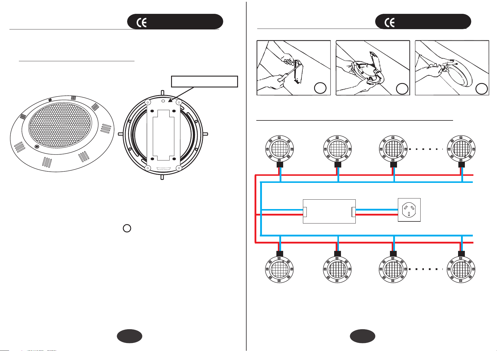
Mounting bracket
IP 68
lnstruction Manual
1
ROHS
2
IP 68
Figure 3
Connect pool lights to the transformer:
LED lamp
3
POOL light Front
POOL light Back
Figure 1
Figure 2
1.Drill 4 holes for the mounted bracket. install the bracket to
the pool wall. The Diagram 1 in Figure 3
2. Connect the buckle of the pool light to the bracket buckle.
and screws the light to the mounting bracket.
3.Finish area surrounding mounting spacer must be flat and
flush with the face of mounting spacer, this ensures a snug
fit between light and wall
4.Wrap a length of the cable up to a maximum of 4ft=122cm
long on the back the light out of the pool for maintenance.
5.Connect all wires in the junction box and feed paraffin.
6.Secure the junction box cover in place and make sure all
gasket/seals fit in properly
1 2
lnput AC 110V/2 20V
AC12 V
N
L
tr ansfo rmer
LED lamp
BLACK CAB LE
N
L
RED CABLE
Figure 4
Power110 V/220V
Please note: The input voltage of the lamp is AC12V.So
you mustuse an AC110V/220V to AC12V transformer to
connect the lamp
Page 2
lnstruction Manual lnstruction Manual
ROHS
IP 68
ROHS
IP 68
POOL LIGHT series Underwater
Light Operating Procedures
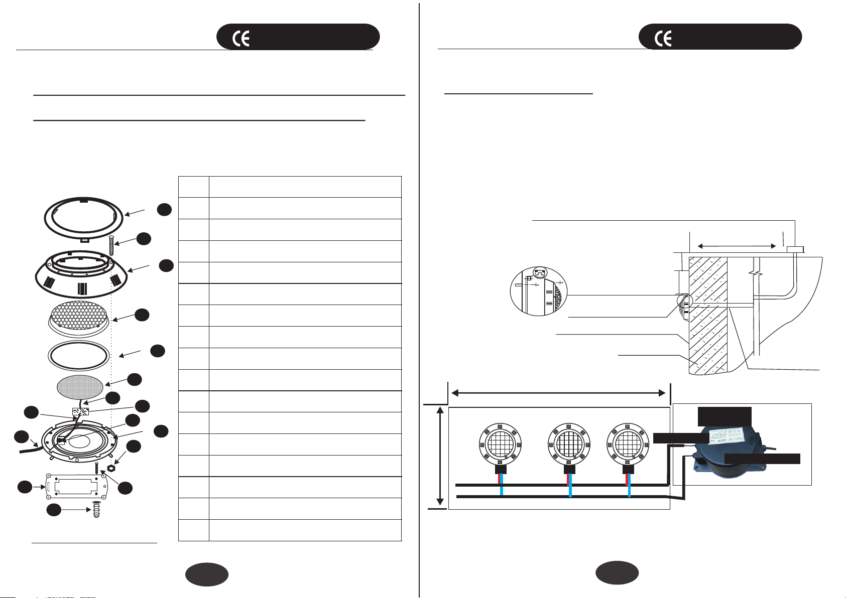
Underwater Light Replacement Parts
See Figure 5.
10
14
Item
1
+
7
9
+
11
2
4
5
6
8
12
13
11
15
1
2
3
3
4
5
6
7
8
9
10
11
12
13
14
Lamp 12Volt LED lamp panel
LED Drive controller
Description
Face Ring
Screw with nut(8)
Cover
Transparent bead cover
Lens Seal
Wires
Wires
Wires
Sealing nut(8)
Sealing O-ring
Body
Hanging plate
PRECAUTIONS:
Make sure power is turned off before installing or removing
lamp Never use the light for function control longer than 10
minutes without being completely under water!!!
The mounting bracket must be properly installed so that the
top edge of the underwater light’s lens is approximately
1.5ft=45cmbelow the surface of the water in the pool. See
Figure 6.
Installation diagram
Figure 6
4.8 m=16i n
TO GF OL CI RCU IT BR EAKER AN D POWER S OUR CE
MIN. FR OM BO TTO M OF
JUNCT ION B OX OR LOW V OLTAGE
TRANS FOR MER TO WATER LIN E
MIN. FR OM WATE R LINE
TO TOP O F LEN S
MP IL OT SC REW AT TOP
THE DEC ORAT IVE S UAFACE
POLL WALL
9.6 m=32i n
15 Wx3 PCS
output AC12V
30CM
45CM
120CM MIN
AC1 2V
tr ans for mer
RIGID C OND UIT
lnput AC110V/ 220 V
16
COMPONENT
Figure 5
15
16
3
Screw with nut(4)
Colloidal particles
Recommended installation drawing
Figure 7
4
 Loading...