

Page 1
Link Controls
Stuart Road, Manor Park, Runcorn, Cheshire, WA7 1TS
T: +44 (0)1928 579050 F: +44 (0)1928 579259 www.linkcontrols.co.uk [email protected]
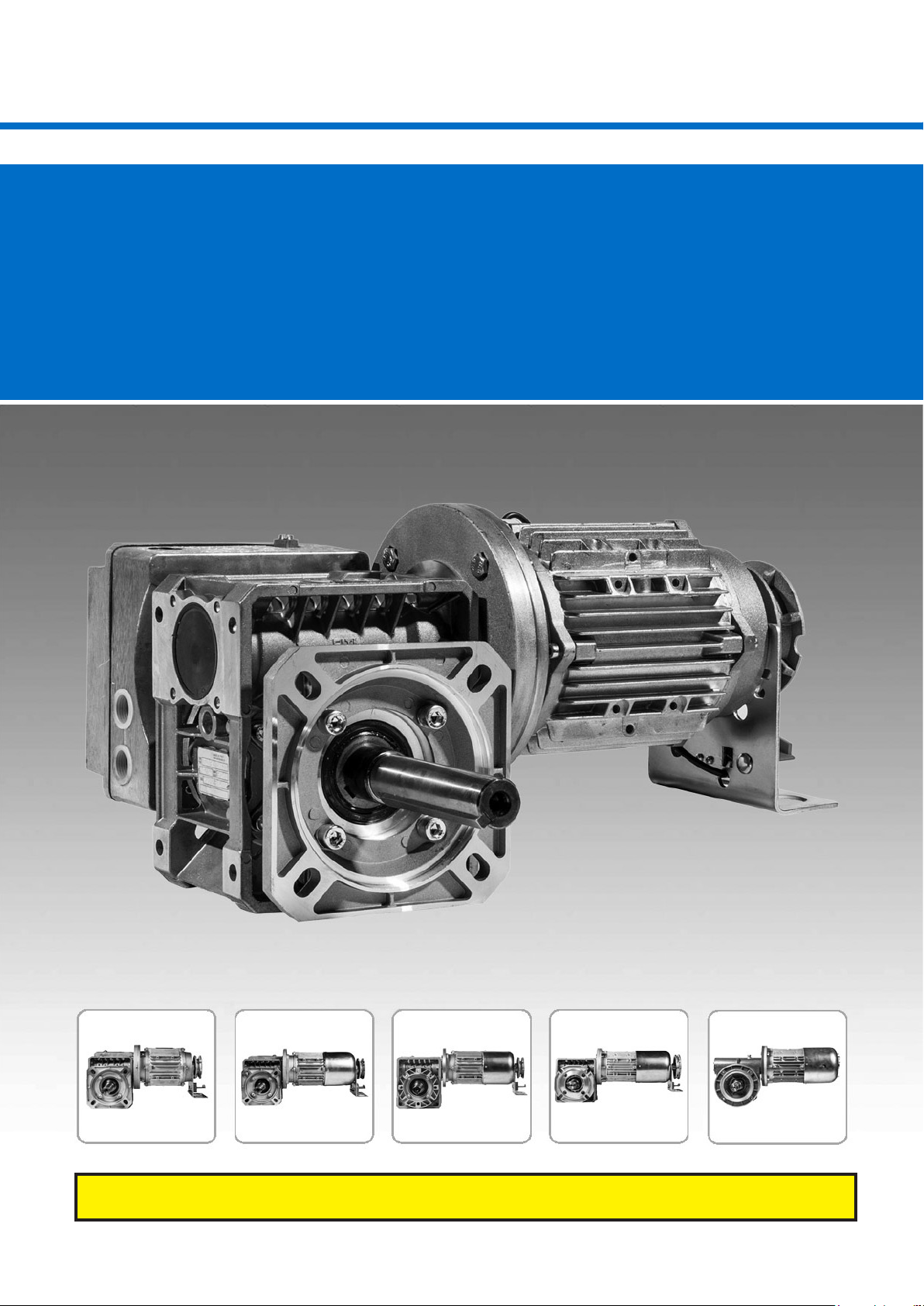
Instructions for Rolling Door Operator type :
CDO
Warning : Please read these instructions fully before installation
Door Operator / CDO/ LC-3158 Rev.B
Page 2
1. Contents 3. General safety instructions
1. Contents 2
2. Key to symbols 2
3. General safety instructions 2
4. Overview of products 3
5. Installation 4
6. Initial Operation 6
7. Emergency operation 10
8. Maintenance 11
9. EU Declaration of Conformity 12
Guarantee
The function and safety of the equipment is only guaranteed
if the warning and safety instructions included in these
operating instructions are adhered to.
Link Controls is not liable for any personal injury or damage
to property that occurs as a result of the warning and safety
instructions being disregarded.
Link Controls does not accept any liability or warranty for
damage due to the use of non-approved spare parts and
accessories.
Using the equipment for its intended purpose
Operators of the CDO range are designed exclusively for
opening and closing roller shutter doors (complete with
installation of a safety brake as required)
Target group
Only qualied and trained specialists are permitted to install
and service the operator. Qualied and trained professionals
full the following requirements:
- knowledge of the general and specic safety and accident
prevention regulations,
- Knowledge of the relevant regulations,
- trained in the use and care of appropriate safety equipment,
- Capable of recognising the dangers associated with
installation.
2. Key to symbols
Danger of personal injury!
The safety instructions must be
observed!
Warning! Danger to property!
The safety instructions must be
observed!
Information
Special information
OR
Reference to other sources of
information
Only qualied and trained electricians may connect the
operator and carry out electrical maintenance.
Qualied and trained electricians full the following
requirements:
- knowledge of the general and specic safety and accident
prevention regulations,
- knowledge of the relevant electrical regulations,
- trained in the use and care of appropriate safety
equipment,
- capable of recognising the dangers associated with
electricity.
Instructions for installation and connection
- The controls must be disconnected from the electricity
supply before carrying out electrical works. It must be
ensured that the electricity supply remains disconnected
during the works.
- Local protective regulations must be complied with.
- Mains cables and control cables must be laid separately.
2 – Door Operator / CDO / LC- 3158 Rev.B
Page 3
4. Overview of products
Regulations and bases for testing
For connecting, programming and servicing, the following
regulations must be observed (the list is not exhaustive).
Construction product standards
- EN 13241-1 (Products without re resistance or smoke
control characteristics)
- EN 12445 (Safety in use of power operated doors -
Test methods)
- EN 12453 (Safety in use of power operated doors -
Requirements)
- EN 12635 (Industrial, commercial and garage doors and
gates - Installation and use.)
- EN 12978 (Safety devices for power operated doors and
gates - Requirements and test methods)
Electromagnetic compatibility
- EN 55014-1 (Radio disturbance, household appliances)
- EN 61000-3-2 (Disturbances in supply systems -
harmonic currents)
- EN 61000-3-3 (Disturbances in supply systems -
voltage uctuations)
- EN 61000-6-2 (Electromagnetic compatibility (EMC) -
Part 6-2: Generic standards - Immunity for industrial
environments)
- EN 61000-6-3 (Electromagnetic compatibility (EMC) -
Part 6-3: Generic standards - Emission standard for
residential, commercial and light- industrial environments)
Various options
The following package options are available for the
ange mounted CDO Rolling Door operator:
The operators listed below can be supplied with
various manual overrides.
CDO-50 1ph
CDO-100 3ph / 1ph
CDO-150 3ph
CDO-175 3ph
CDO-200 3ph / 1ph
CDO-275 3ph
CDO-300 3ph
CDO-375 3ph
CDO-400 3ph
Machinery guidelines
- EN 60204-1 (Safety of machinery, electrical equipment of
machines, part 1: general requirements)
- EN 12100-1 (Safety of machinery. Basic concepts,
general principles for design. Basic terminology,
methodology)
Low voltage
- EN 60335-1 (Household and similar electrical
appliances - Safety)
- EN 60335-2-103 (Particular requirements for drives for
gates, doors and windows)
Door Operator / CDO / LC- 3158 Rev.B – 3
Page 4
5. Installation
5.1 Preparation
Danger!
To avoid injury, the following points must
be observed:
- The operator must be installed free of
any tension.
- The operator must not move on the
mounting bracket.
- The design and subsurface of all
components must be suitable for the
forces encountered.
Warning!
To avoid damage to the operator and the
door, the operator must only be tted if:
- the operator is undamaged,
- the ambient temperature is -20 ºC to
+60 ºC,
- the altitude of the location does not
exceed 1,000 m,
- a suitably rated mains protection device
has been selected.
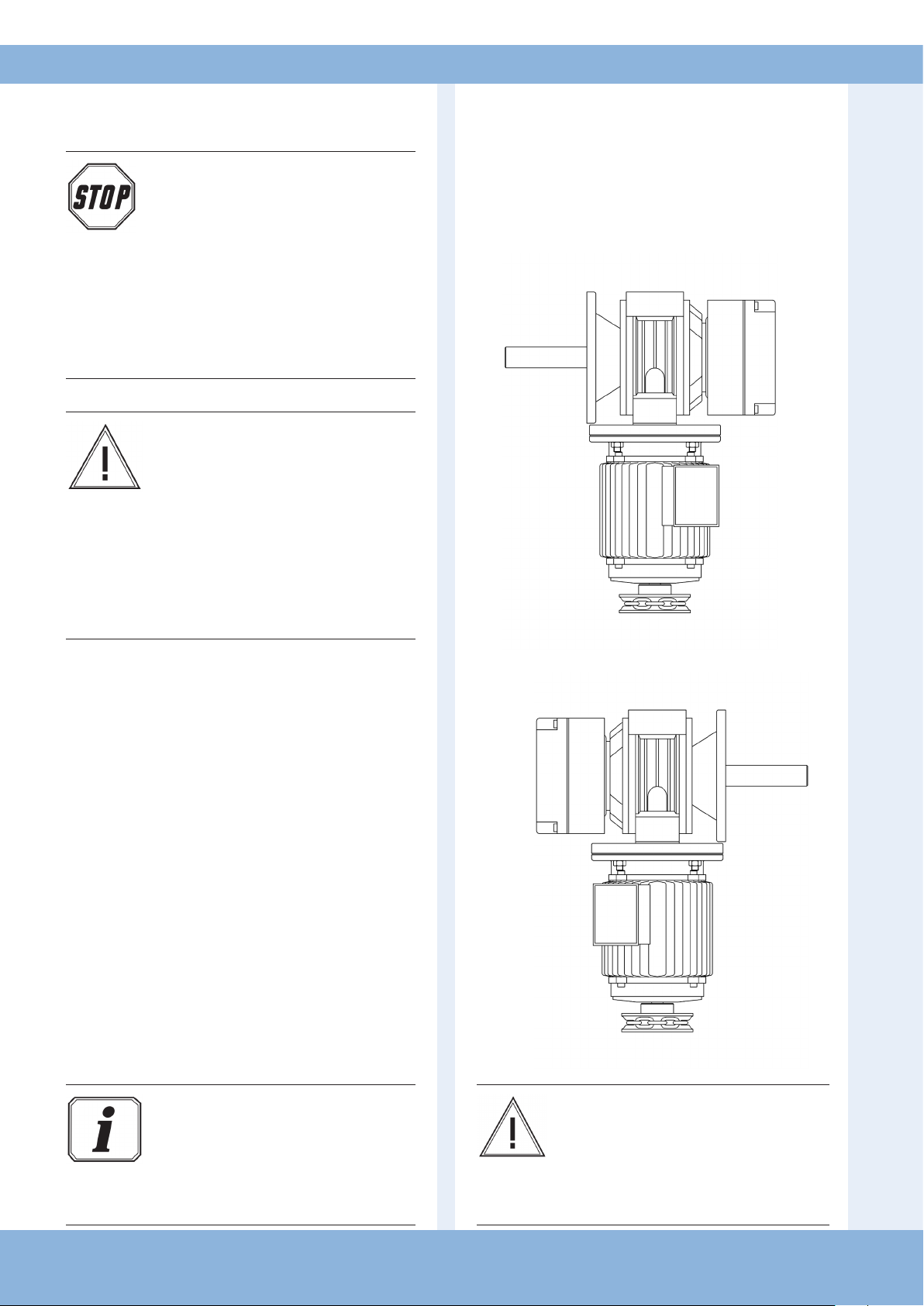
5.2 CDO Operator - Flange Mount Handing
Handing the operator
The CDO Range of operators can be supplied for
left or right hand installation. Please refer to the
diagram below when ordering.
As viewed from above
Handing ‘1A’
☞ Before installation, ensure that:
- the operator is not blocked,
- the operator has been newly prepared after a lengthy
- storage period,
- all connections have been carried out correctly,
- the direction of rotation of the drive motor is correct,
- all motor protective devices are active,
- no other sources of danger exist,
- the installation site has been cordoned o over a
wide area.
Information
The relevant instruction for the door must
be observed when tting the drive to the
door.
- a suitably rated mains protection device
must be selected.
As viewed from above
Handing ‘1B’
Warning!
Damage due to improper installation the
drive! To avoid damage to the drive and to
the door, the drive must be mounted on a
torque support bracket that it is vibration
damped.
4 – Door Operator / CDO / LC- 3158 Rev.B
Page 5
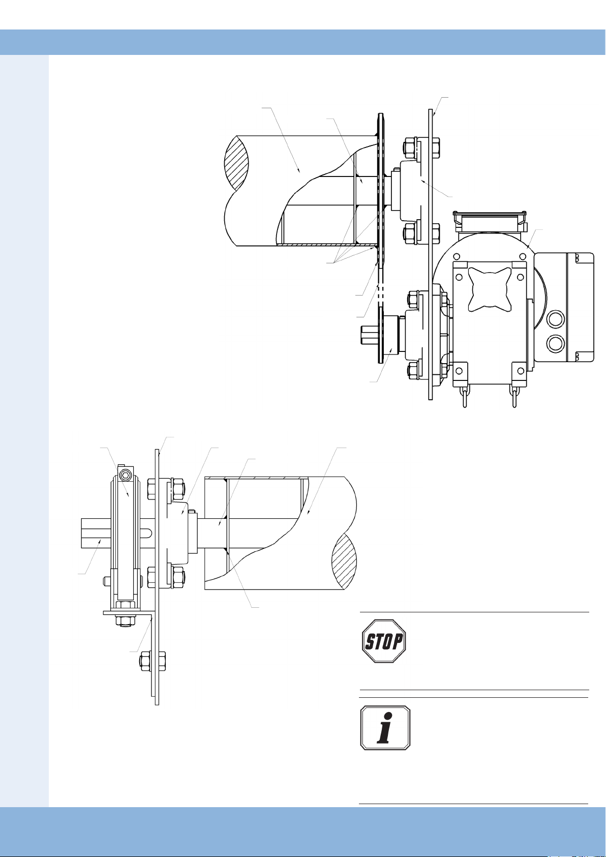
5.3 Mounting using sprocket
and chain - typical example
End Plate
Shutter Barrel
Drive End Shaft
Self-Aligning Flange Bearing
CDO Operator
Weld into Position
Plate Wheel
Drive Chain
5.4 Dummy end / safety brake
- typical example
End Plate
Key
Brake Mounting
Self-Aligning Flange Bearing
Dummy End Shaft
Weld into Position
Sprocket
Shutter BarrelSafety Brake
Danger!
A safety brake or equivalent device must
be tted to the dummy end of the shutter
barrel to protect the safety of the machine
against drive chain failure.
Information:
Link Controls Ltd. constantly strives to
improve the quality of its goods and as
such reserves the right to replace/modify
products without prior notication. Any
examples given are intended for guidance
only.
Door Operator / CDO / LC- 3158 Rev.B – 5
Page 6

5. Installation
6. Initial Operation
5.5 Installation of the emergency hand chain
(for operators with emergency hand chain)
Information:
To ensure that they work correctly, the
chain links must not be twisted.
6.2 Motor Connections
‘Standard’ 3ph Motor Connection
3 x 400V Star connection (standard)
The motor should be congured as shown above
for connection to a 3 x 400V control panel.
☞ Join the ends of the emergency hand chain together
with a chain connecting link.
Warning!
To avoid damage to the operator and
the door, the emergency hand chain
must be safely secured (for example in a
‘chain keep’ ) while the door is operated
electrically.
6.1 Preparation
Warning!
To avoid damage to the operator, the
following points must be observed:
- The types of cable and their diameters must be selected
according to current regulations.
- The nominal currents and the type of connection must
correspond to those on the motor type plate.
- The drive details must agree with the connected loads.
'400V / 690V' 3ph Motors Connection
3 x 400V Delta connection (CDO375 & CDO400)
The CDO375 & CDO400 should be congured as shown
above for connection to a 3 x 400V control panel.
Information:
When operated with electronic control units,
the corresponding start-up instructions and
circuit diagrams must be complied with.
6 – Door Operator / CDO / LC- 3158 Rev.B
Page 7
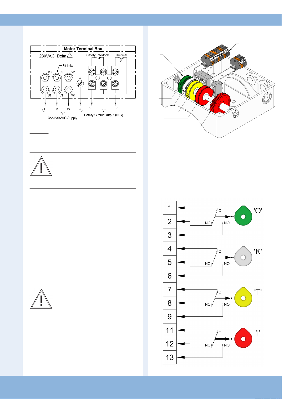
‘Inverter Drive’ 3ph Motor Connection
'K'
'T'
'I'
Worm Gear
Control / Limit
Cams
Terminals
3 x 230V Delta connection (inverter)
The motor should be congured as shown above
for connection to a 3 x 230V control panel.
Warning!
Ensure the correct motor connection
conguration is used to avoid damage
to the motor. Do not use ‘230 VAC Delta’
connection for 3ph/400VAC control panels.
6.3 Mechanical Limit Switches
'O'
'O' Control cam for limit switch, CLOSED (green)
'K' Control cam for limit switch, OPEN (white)
'T' Control cam for limit switch, AUX (yellow)
'I' Control cam for limit switch, AUX (red)
Limit Switch Connections (microswitches)
Safety Circuit
The safety circuit combines the Thermal Trip and,
for operators with Manual Override, the Interlock
Switch.
The Thermal Trip is a heat sensitive switch
embedded in the motor windings that will operate
should the motor be overloaded.
The Hand Chain Interlock provides a means
of control circuit isolation to prevent electrical
operation whilst the door is being operated
manually.
Warning!
To ensure compliance with BS 7671 wiring
regulations (IET) the Thermal Trip must
be connected into the relevant controller
safety circuit (Stop circuit).
Note:- For operators with a disengage clutch, the
disengage switch output must be connected in
series with the motor safety circuit (N/C).
Door Operator / CDO / LC- 3158 Rev.B – 7
Page 8
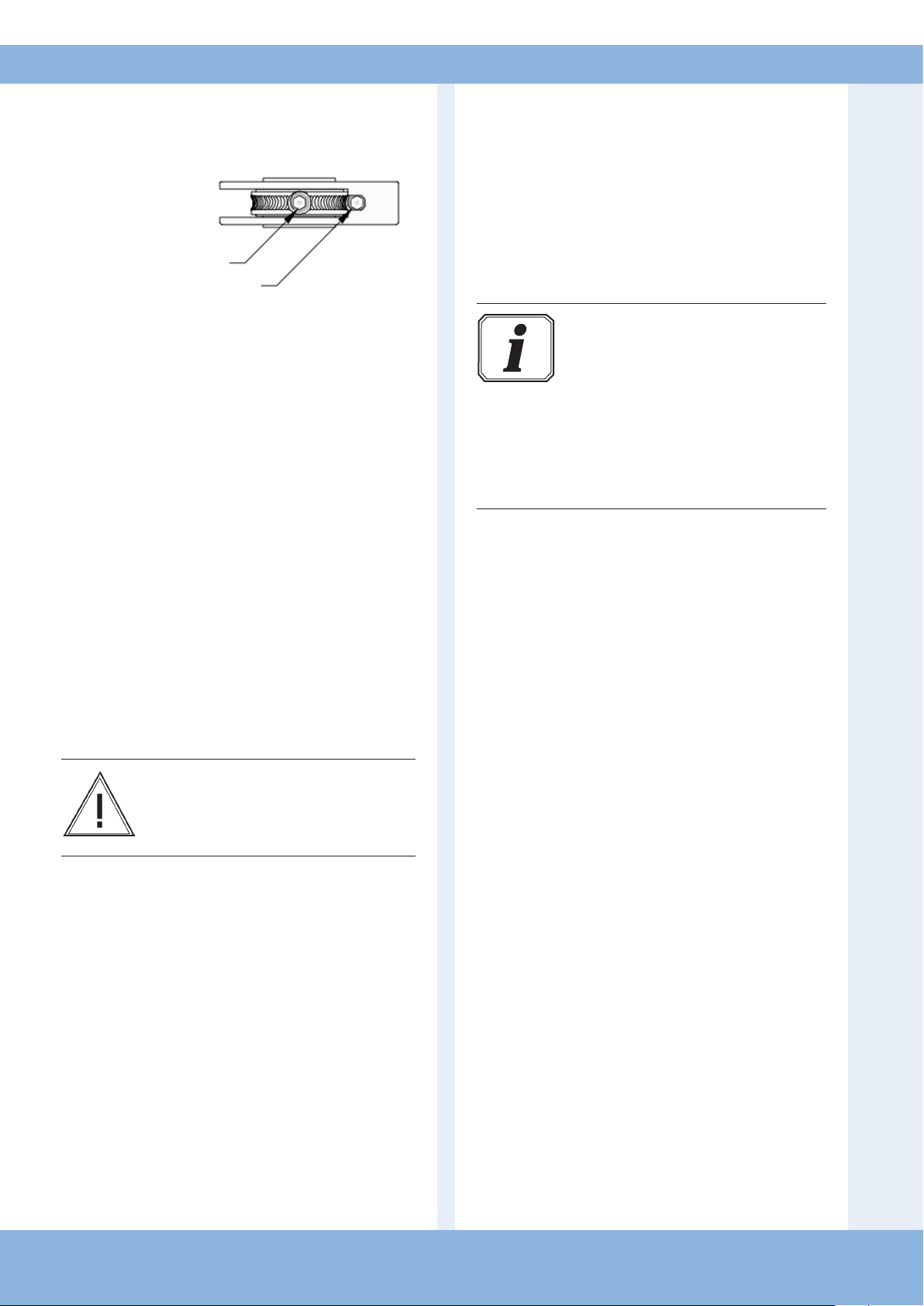
6.4 Setting Mechanical Limits
Fine Adjustment Screw
Locking Screw
6.5 Check the system
Control / Limit Cam Adjustment
Each control cam has a locking screw and a ne
adjustment screw.
The locking screw is used to lock the
corresponding control cam in the desired position.
Finer adjustment can be made with the ne
adjustment screw.
Set the CLOSED end position
☞ Drive the door to the CLOSED end position.
☞ Set the control cam ('O' - GREEN) so that the
CLOSED limit switch is actuated.
☞ Tighten the locking screw.
Set the OPEN end position
☞ Drive the door to the OPEN end position.
☞ Set the control cam ('K' - WHITE) so that the
OPEN limit switch is actuated.
☞ Tighten the locking screw.
Warning!
To avoid damage to the operator it is
important that all unused cams MUST be
locked in position
Check the direction of travel
☞ Drive the door in the CLOSED direction.
The operator must close the door.
☞ Drive the door in the OPEN direction.
The operator must open the door.
Information:
If the door’s direction of travel does not
correspond to the commands keyed
in, then the direction of rotation must
be changed. Instructions for changing
the direction of rotation are given in the
control unit operating manual.
After this the direction of travel must be
checked again.
Check the limit switch settings
☞ Drive the door to the CLOSED end position.
The operator must stop in the desired position.
☞ Drive the door to the OPEN end position.
The operator must stop in the desired position.
Check the mechanical functions
After assembling and installing all components the
functions of the system must be checked.
☞ Check that all mountings have been securely
tightened.
☞ Check all the functions of the system.
☞ Check that the operator runs smoothly.
☞ Check whether the operator is leaking oil.
8 – Door Operator / CDO / LC- 3158 Rev.B
If the operator makes unusual noises or leaks oil:
- The operator must be taken out of service immediately,
- Contact technical support.
Page 9
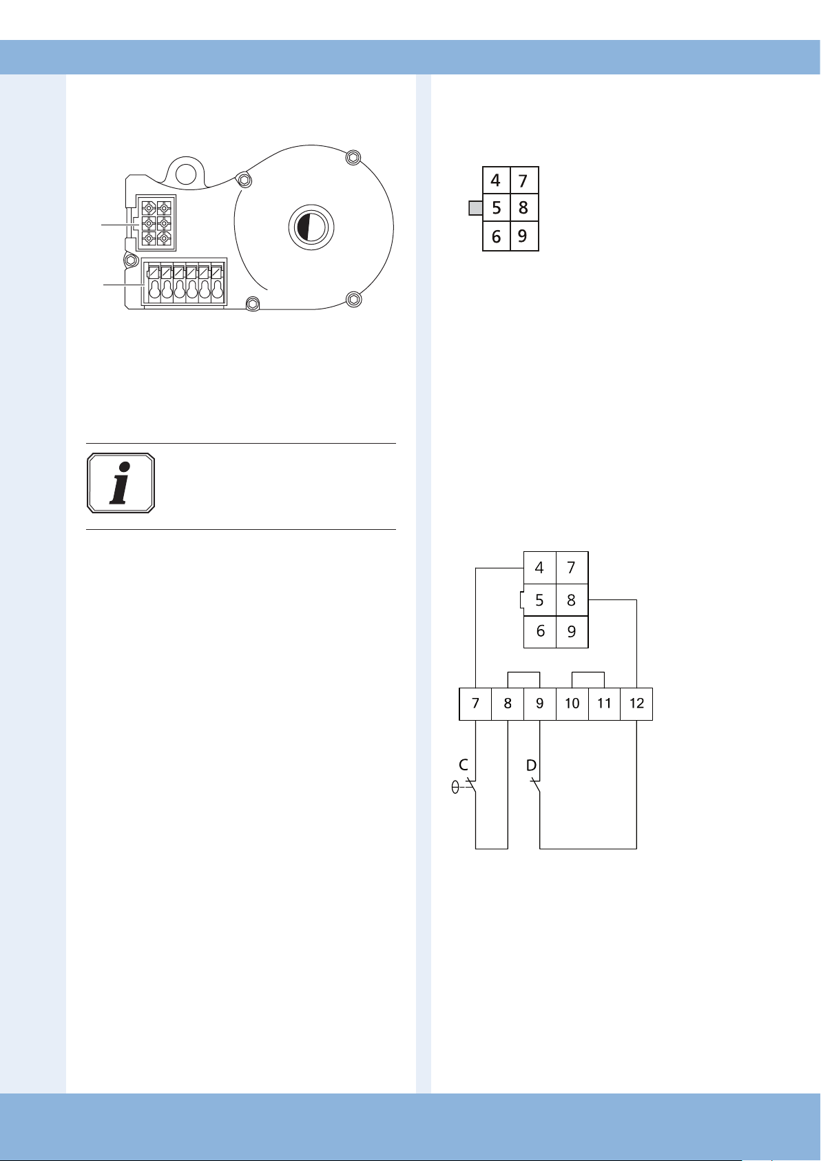
6.6 Digital Limits
Electronic interface
A
Wiring allocation,
AVE (absolute value encoder) plug
B
A: AVE plug (absolute value encoder plug)
B: AVE plug terminal (absolute value encoder
plug terminals.
Information:
Please refer to the control unit operating
manual for instructions on setting the limit
end positions.
The numbers on the plug are also the wire
numbers.
4: Safety circuit input (N/C)
5: RS 485 B
6: GND
7: RS485 A
8: Safety circuit output (N/C)
9: 7...18V
DC
AVE (absolute value encoder) plug terminal (7-12)
C: Thermal element in the drive
D: Manual emergency control
(emergency crank or emergency chain)
Door Operator / CDO / LC- 3158 Rev.B – 9
Page 10
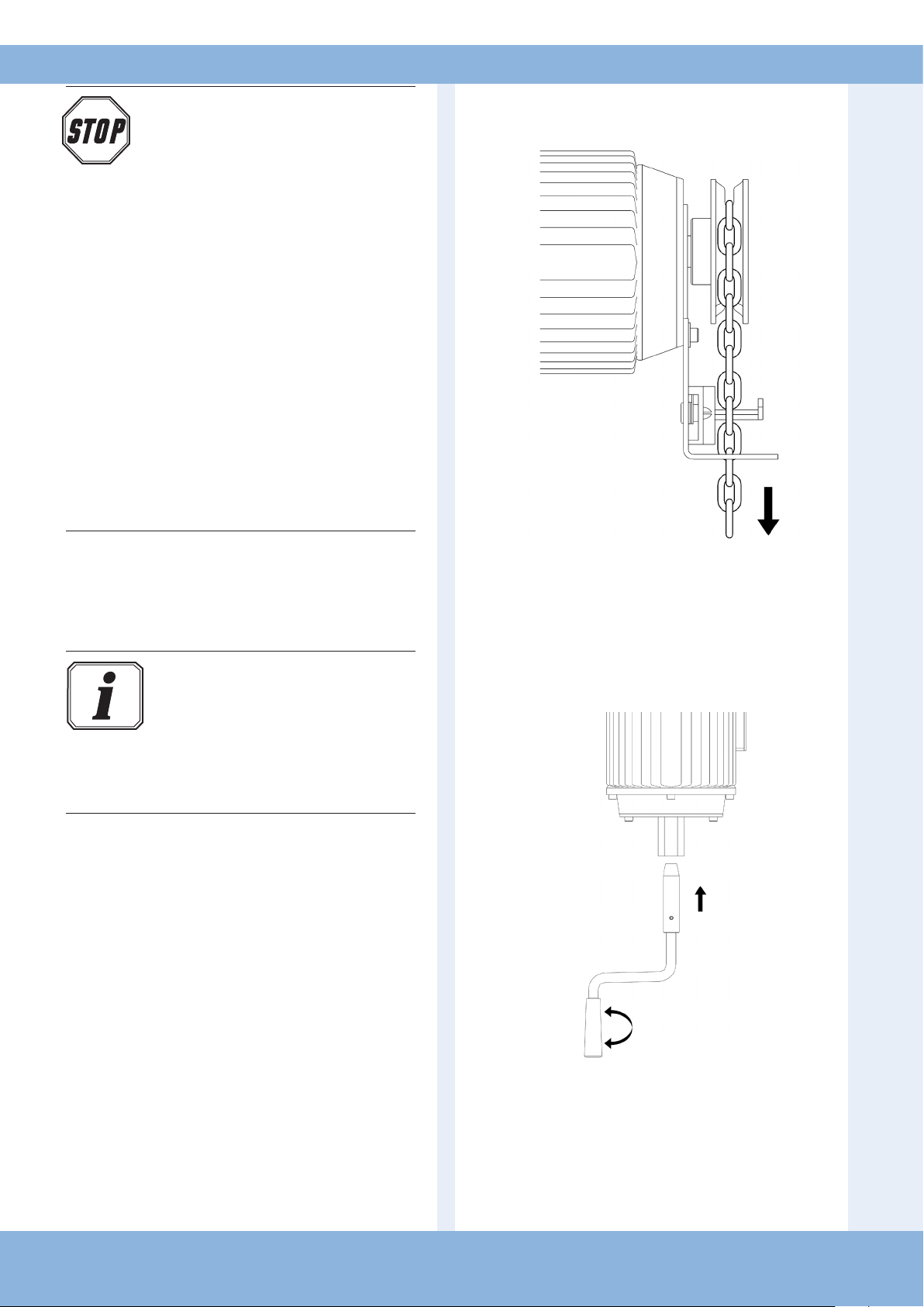
7. Emergency Operation
Danger!
To avoid injury, the following points must
be observed:
- Emergency operation may only be
carried out from a safe standing position.
- Emergency operation may only be
carried out when the motor is stationary.
- The system must be disconnected from
the power supply during emergency
operation.
- Operators with a spring brake must be
actuated against the closed brake when
opening or closing the door.
- For safety reasons, brakes in doors
without a weight counterbalance must
only be released in the closed door
position for testing purposes.
- Accidental releasing of the brake must
be rendered impossible by preventive
measures at the installation site.
Operation with emergency wheel
guide & interlock
During maintenance works or in the case of an electrical
failure, the door can be moved towards the OPEN or
CLOSED positions with the help of the emergency
manual override equipment.
Information:
If the door is moved beyond the CLOSED
or OPEN end positions, the operator
may no longer be activated electrically
- place the door back into a normal
position before attempting powered
operation.
☞ Lift the handchain o the safety switch and place
it on the chainwheel.
☞ The Door can now be operated by hand chain.
Before power is restored, the above procedure
must be reversed
Operation with emergency hand crank
10 – Door Operator / CDO / LC- 3158 Rev.B
☞ Push the emergency hand crank into the operator
as far as it will go.
☞ Move the door in the OPEN or CLOSE direction
by turning the emergency hand crank.
☞ Remove the emergency hand crank from the
operator after completing emergency manual
operation.
Page 11
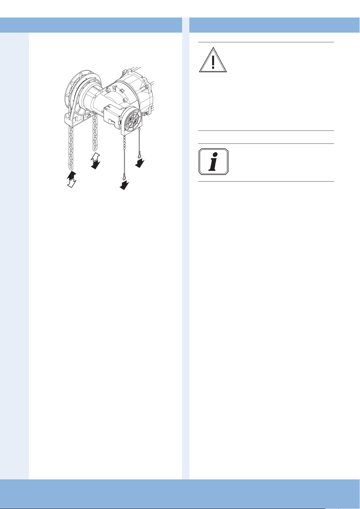
Operation with emergency oor level
hand chain (KE)
Releasing
☞ Gently pull the cable with the red handle downwards as
far as possible. The control voltage will be interrupted
and the door can no longer be operated electrically.
☞ Release the emergency hand chain from its xing.
☞ Move the door in the OPEN or CLOSE direction by
pulling on the emergency hand chain on the side
concerned.
8. Maintenance
Warning!
To avoid damage to the operator and door,
the following points must be observed:
- Maintenance must only be carried out by
authorized persons.
- Directive BGR 232 must be complied with.
- Worn or faulty parts must be replaced.
- Only approved parts may be installed.
All maintenance work must be
documented.
Information:
The drive unit has lifetime lubrication and
is maintenance-free.
☞ Check that all mountings have been securely
tightened.
☞ Check the brake (if available).
☞ Check the limit switches and safety switches.
☞ Check for noises and oil leaks.
☞ Check the mounting of the operator for corrosion.
☞ Check the housing for damage.
Locking
☞ Gently pull the cable with the green handle downwards
as far as possible. The control voltage will be switched
on again and the door can be operated electrically.
☞ Attach the emergency hand chain to its xing.
The door can now be moved with the operator.
Door Operator / CDO / LC- 3158 Rev.B – 11
Page 12
9. EU Declaration of Conformity
We hereby declare that the products described below:
CDO-50 / 100 / 150 / 175 / 200 / 275 / 300 / 375 / 400 Door Operator
are in conformity with the essential requirements of the Machinery Directive 2006/42/EC.
In addition, the partly completed machinery is in conformity with the Electromagnetic
Compatibility Directive 2014/30/EU and the Low Voltage Directive 2014/35/EU.
The following standards were applied:
EN 60204-1 Safety of machinery, electrical equipment of machines - Part 1:
General requirements
EN ISO 12100 Safety of machinery - Basic concepts, general principles for
design
EN 12453 Safety in use of power operated doors - Requirements
EN 12604 Industrial, commercial and garage doors and gates - Mechanical
aspects - Requirements
EN 61000-6-2 Electromagnetic compatibility (EMC) - Part 6-2: Generic
standards - Immunity standard for industrial environments
EN 61000-6-3 Electromagnetic compatibility (EMC) - Part 6-3: Generic
standards - Emission standard for residential, commercial and
light-industrial environments
EN 60335-2-103 Particular requirements for drives for gates, doors and windows
The relevant technical documentation is compiled in accordance with Annex VII(B) of
the Machinery Directive 2006/42/EC. We undertake to transmit, in response to a
reasoned request by the market surveillance authorities, this documentation in electronic
form within a reasonable period of time.
Person authorised to compile the relevant technical documentation:
Link Controls, Stuart Road, Manor Park, Runcorn, Cheshire, WA71TS
The machinery is incomplete and must not be put into service until the machinery into
which the partly completed machinery is to be incorporated has been declared in
conformity with the provisions of the Machinery Directive 2006/42/EC.
Place / Date:
Runcorn, 20/04/2016
Manufacturer’s signature:
Certicate Number 10668
ISO 9001
Link Controls Ltd. reserves the right to change / modify products without prior notication
12 – Door Operator / CDO / LC- 3158 Rev.B
02/01/2018
 Loading...