


1/80
1/40
Slim IP Cam V2

2/80
2/40
Index
1. Models................................................................................................................................................. 4
2. Description .......................................................................................................................................... 5
2.1 Power ............................................................................................................................................ 6
2.2 Relays Connection ........................................................................................................................ 6
2.3 Physical installation ...................................................................................................................... 7
2.4 Micro SD card ................................................................................................................................ 8
3. Services ............................................................................................................................................... 8
3.1 Signaling ........................................................................................................................................ 8
3.2 Call ................................................................................................................................................. 8
3.3 Code lock ..................................................................................................................................... 10
4. Parameters programming ................................................................................................................ 10
4.1 After login ................................................................................................................................... 10
4.2 Login ............................................................................................................................................ 10
4.4 Language settings ....................................................................................................................... 12
4.5.1 SIP setting ............................................................................................................................ 14
4.5.2 WEB server ........................................................................................................................... 16
4.6 Basic settings ............................................................................................................................... 17
4.6.1 Phonebook ........................................................................................................................... 17
4.6.2 Relays ................................................................................................................................... 18
4.6.3 Sensors ................................................................................................................................. 21
4.6.4 SNMP .................................................................................................................................... 22
4.6.5 Timetable ............................................................................................................................. 23
4.6.7 Date and time setting .......................................................................................................... 24
4.6.8 E-mail ................................................................................................................................... 25
4.7 Extended settings ....................................................................................................................... 27
4.7.1 DoorPhone ........................................................................................................................... 27
4.7.2 Audio and codecs settings ................................................................................................... 29
4.7.3 Video and video codecs settings ......................................................................................... 31
4.7.4 Streaming ............................................................................................................................. 33
4.8 Service ......................................................................................................................................... 34
4.8.1 Restart .................................................................................................................................. 34
4.8.2 Configuration ....................................................................................................................... 35
4.8.3 Style and language ............................................................................................................... 36
4.8.4 Firmware upgrade ............................................................................................................... 37

3/80
3/40
4.8.5 Logfile ................................................................................................................................... 38
4.8.6 License .................................................................................................................................. 39
4.8.7 User acoustic tones .............................................................................................................. 40

4/80
4/40
1. Models
1 Button with Cam 2 Buttons with Cam 4 Buttons with Cam

5/80
5/40
2. Description
1. Mounting holes
2. Cabling holes
3. First relay
4. Second relay
5. MicroSD card slot
6. Input for powering SLIM IP CAM V2 12V AC / DC (consumption cca 300mA max.) We recommend
DC power supply
7. Output 12V DC, max. 300mA, for example to power low consumption electrical lock via POE
powering of SLIM IP CAM V2
8. UTP cable connection (Ethernet, LAN, net)
9. The LED to control network activity,
green = connection 100M LAN, yellow =
data transmission on the LAN
10. Connector keypad module
11. DIP switch:
1- always ON
2- OFF, when is ON during start then
default IP adress 192.168.1.250 is
setup
3, 4- OFF not used
12. IP module
13. Connector for a 3
rd
button or 1 button
and 2 door sensors
14. Camera lens (for camera models only).
The lens angle is 110°, with a maximal
Resolution of 640x480,by turning thelens
you can focus on the picture
15. Signaling LED
- red – current call
- green – call in progress
- orange – relay closed
16. Light night – white LED with intensity
setting

6/80
6/40
17. Ambient light sensor – Connector to connect 3
18. Connector to connect speaker
19. Connector to connect microphone
rd
button
2.1 Power
The SLIM IP CAM V2 is equipped by circuit for powering via UTP cable – POE. When you use electrical
lock for door opening then you have to use PSU for powering door electrical lock (in relays contacts
circuit only), or use low consumption electrical lock and for electrical lock powering use output screw
“12V output” (7). When POE is used then 12V/300mA is available.
CAUTION: There must not be activated both electrical locks simultaneously.
2.2 Relays Connection
Relay connection (3) and (4) :
- NO means idle - disconnected contact,
- COM means a pin contact (middle)
- NC means an idle - connected contact.

7/80
7/40
2.3 Physical installation
Wall mounting installation
Installation place
To reach good video quality the camera must not point directly to:
- Sun lighting
- Strong light sources
- Light or strongly reflective walls
Installation height
Installation height of outdoor video station should be selected
according camera scan range (via picture). Small size persons will be
optimally scanned with an installation 160 cm at from ground.

8/80
8/40
Status
Tone
LED
Call start
Adjustable / user programmable
RED
Call end
Adjustable / user programmable
OFF
Call not possible (busy)
Adjustable / user programmable
RED
Confirmation of code insert
Adjustable / user programmable
GREEN
End of call notification
Adjustable / user programmable
GREEN
Relay closing
Adjustable / user programmable
RED+
GREEN
Error
Adjustable / user programmable
Button press
Adjustable / user programmable
2.4 Micro SD card
Micro SD card is used to save users sound files and also to save pictures, video,… When you select
users tone and microSD will not be inserted then tones of basic signaling will be used.
Never take out SD card during door entry operation!
3. Services
3.1 Signaling
The door entry SLIM IP CAM V2 signals acoustically the different stages which occurs during
operation. Signaling uses 2 LED colors . Acoustical signaling, for each status mentioned in the table
below, might be switched off or might use default tones or “beeping” recorded by the user.
3.2 Call
When the visitor press appropriate button and door entry start calling immediately or delayed (time
between button press) .The door entry dials preprogrammed number. The way the number is dialled
is made according to the way it is set in phone bookPhone book position for selected button must be
allowed
1. It is mandatory to fill in 1 of the 3 phone numbers (or IP addresses in P2P mode)
2. The position of the selected directory should be allowed for the buttons

9/80
9/40
The calling plan is followed according to the selected option, the default call numbers in order (1- 2 -
3), otherwise you can make calls on several numbers simultaneously and whoever wins the first to
provides call management.
Both versions of dialing can be combined. For example it is possible to call number 1. and number 2
simultaneously. When call is not picked up after a certain time then number 3 is dialed.
Repeated button press might have following results:
- Nothing happen
- Dial again
- Call is ended

10/80
10/40
3.3 Code lock
Authorize the opening of the portal by dialing a combination of the two keys. If the visitor presses
the buttons respecting the combination input and within the time specified on the time table, the
door phone will trigger the corresponding relay.
4. Parameters programming
4.1 After login
Before first start of SLIM IP CAM V2 door entry firstly check positions of DIP switch. Each switch
should be in positions as shown in the picture below.
1 – On
2 – Off
3 – Off
4 – Off
Meaning of each switch:
1. Always in on position. This switch is only used for production or service.
2. When is on during power supply start (or reset), then the default IP address 192.168.1.250 is
configured; operative position is off, currently not used
3. off, currently not used
4.2 Login
In your Web browser, type the IP address of the gateway IP Slim V2; the default address is
92.168.1.250. You can see the image of the camera as shown below – “home screen with video”
Default User name is « admin», password is «1234».

11/80
11/40
4.3 Current status
The display of the device status is in the "Current Status" tab. You will find:
- The name of the door phone
- The firmware version
- The number of buttons
- Options (camera, keyboard)
- The SD card
- The MAC address
- The IP address
- SIP Mode or P2P
- Recording Status......

12/80
12/40
4.4 Language settings
On the upper right corner is displayed the flag of the language used in the web interface. By clicking
on the flag available languages are displayed. After selecting the language, click "Save" so that the
language selection be effective.

13/80
13/40
4.5 IP network setting
Network settings you find in menu “Network setting”. Click on Network, then you can select the use
of a fix IP address or a dynamically assigned IP address (DHCP mode).
After performing the required changes please don’t forget to click on “Save and restart”.
DHCP : Enable / Disable DHCP configuration In manual configuration, configure :
- IP adress,
- Network mask: IP adress setting, mask. In case of emergency please contact your network
administrator.Network gateway: Router IP adress (Internet connection).
- DNS server 1 and 2: IP adresses of primary and secondary domain server.
Important: If you use the DHCP configuration then assignment of the IP address to the Door Phone
will happen automatically; the network administrator have to allow your IP address to be able to
show videos in the Web browser. Therefore, as this dynamically assigned IP address can be changed

14/80
14/40
for example due to a power failure, we recommend using the door of Slim IP Cam V2 input with a
fixed IP address.
4.5.1 SIP setting
The Door Phone IP Cam Slim V2 operates in two basic modes.
- In SIP server mode : Recording the gate input is made to the SIP server, and then you call the
telephone numbers assigned by the SIP server;
- In Peer to Peer Mode (P2P): gateway calls the exact IP address and SIP server services cannot
be used.
Display name: unit name in SIP protocol (usually line number).

15/80
15/40
Account / Auth.ID: name for SIP server registration.
Password: password for SIP server registration.
Send registration: when registration is necessary (this will be the case most of the time) then this
parameter must be used.
Registration server: IP address or server name of registration server (in most systems and
installations is enough to insert IP address). Registration is performed on this server. When you don’t
mark send registration then don’t fill Registration server and IP address soft SIP server write to Proxy
server.
Port: SIP port is usually 5060 or 5061.
Expiration [sec]: expiration of SIP server registration (period of registration request repeated
sending).
Registration after restart: when you mark then always during restart will be unregistrated.
SIP Proxy server: IP address or server name. Over this server connection is made. When is not filled
then connection makes on Registration server (but you must mark Send registration).
Port: SIP port is usually 5060 or 5061.
Outbound proxy: IP address or proxy name where is determine where will be sends door entry
requests. If outbound proxy is setup will be INVITE request sends to outbound proxy address.
Outbound proxy is used due NAT. When is not used don’t fill up.
Port: SIP port is usually 5060 or 5061.
Provisional code: determine if during ringing will be sends SIP code “180 ringing” or “183 Session
progress”.
Symmetric RTP enable: by mark is ON. It means that door entry will not send by itself audio to RTP
called party, but wait for called party to send RTP. After send data to same address: port from which
message arrived. It is trick used for bridging NAT
Registration status display on page as visible on picture.

16/80
16/40
4.5.2 WEB server
WEB interface TCP port: possibility to change usual TCP port 80 to other (security reasons).
Service password / Retype password: insert of new access password (default password is 1234) –
length max.40 characters.
Video on start page: Video ON/OFF on home page of WEB interface (mainly from security reasons.
When video is OFF it is accessible after login with password only).
Video protection by password: further protection is secure access by password to
http://ipaddress/video.jpeg (camera picture).

17/80
17/40
4.6 Basic settings
4.6.1 Phonebook
Title: This text has informative character only. In case help displayed, will be shown in the selection
list name.
Email: to this email will be sent Info about missed calls with picture or video or with records (in case
recorder is activated). Email is necessarily filled.
1. Phone number: is phone number with highest priority. It is the first called number (when
progressive dial mode is used).
Time plan: when is not selected, then 1 number is always active. Usage of 1 phone number might be
limited by time plan.

18/80
18/40
Calling: allows creation of groups.
2. Phone number: is phone number which is dialledl as second (when progressive dial mode is used).
2nd phone number will be dialed with compliance to selected time plan and when is filled only.
Timetable: when is not selected, then 2 numbers are always active. Usage of 2nd phone number
might be limited by time plan
Calling: allows create groups
3. Phone number: is phone number which is dialled as third (when progressive dial mode is used).
3th phone number will be dialed with compliance to selected time plan and when is filled only.
Timetable: when is not selected, then 3rd number is always active. Usage of 3rd phone number might
be limited by time plan
Calling: allows create groups.
4. Phone number: is phone number which is dial as fourth (when progressive dial mode is used). 4th
phone number will be dialed with compliance to selected time plan and when is filled only.
Timetable: when is not selected then 4th number is always active. Usage of 4th phone number might
be limited by time plan.
Calling: allows create groups.
5. Phone number: is phone number which is dial as fifth (when is used progressive dial mode). 5th
phone number will be dialed with compliance to selected time plan and when is filled only.
Time plan: when is not selected, then 5th number is always active. Usage of 5th phone number
might be limited by time plan
External relay code 1/2/3/4: here insert private codes for code lock. The code lock might be
completed from door phone buttons.
Calling – description
The group means 2 or more phone numbers and those Numbers are dialed simultaneously (all are
ringing together). Who from dialed subscribers pick up first can manage the call and ringing to other
subscribers in group will be ended.
Sequential: this phone number is dialed individually. It is not in group with any other number.
Group start: first phone number in group call
With previous: phone number in group. It is not first and also not last.
Group end: phone number is last from the group
By this setting you can create for every subscriber up to 2 groups or groups with 5 numbers and
make groups combination with individual phone numbers.
4.6.2 Relays

19/80
19/40
In relays setting are accessible 4 relays.
Enable: relay function might be eliminated. Due this will be eliminated synchronization signal for
other relays. Meaning is for example when you want temporarily prevent certain door opening. Then
instead of all codes cancellation and their repeated programming simply prohibit this relay. After
time out you can easily return relay with all codes to original function. When such status repeats
regularly (for example school) you can use time plan.
Timetable: defines time period when relay is working and when not. For example, shops opening
time, schools, etc..
Relay mode monostable: by code is closed and after preprogrammed timeout is open. Using for
electrical lock switching, sliding gates control, button press signalling etc…
Relay mode bistable: by code is closed and stay closed, till moment of open by another code.

20/80
20/40
Delay time: is time, between closing code evaluation and relay closing. It has no influence for open
code which is performed immediately. Closing time is calculated from real relay closing.
Source relay 1 – 4 : relay closing starts closing of the same or other relay.
Synchronization delay: time between synchronization start and its evaluation. Usage for example in
more relays closing combination for one code.
Activation on call:
- None (calling has no influence for relay status)
- Incoming call: relay closed during incoming call. The monostable for preprogrammed time.
The bistable permanently for all call duration.
- Outgoing call: relay closed during outgoing call. The monostable for preprogrammed time.
The bistable permanently for all call duration.
- Incoming as same as outgoing call : relay closed during every call. The monostable for
preprogrammed time. The bistable permanently for all call duration.

21/80
21/40
4.6.3 Sensors

22/80
22/40
4.6.4 SNMP
SNMP (Simple Network Management Protocol)
Community: here is necessary to select exact user of SNMP
Admin address: setup IP address or domain name of client where are sent information according
defined setting
Variable MIB: is designed for identification of none sense numeral chain OID is numeral identification
which definitely identify every value in SNMP communication. OID is created by number sequence
separed by dot. Every dot represents exact level of tree structures into which are OID mapped. The
numeral identification in range of each undertree is not Unixe that is why OID is sent always as whole
unit.

23/80
23/40
4.6.5 Timetable
Timetable name: for easy orientation you can named every profile.
Period setting table: profile is active when current time match with setup periods. Every day might
have up to 3 active periods. Further is possible deactivate whole day (first item on the row select
“Active” – Yes /No).
Activation / deactivation code: when is setup profile status = Active then profile is control by time
plan only. When you switch time profile to not active then profile is not active independently on time
plan.
Active: display current profile status

24/80
24/40
Switch: by click you change profile status
4.6.7 Date and time setting
Time zone: selection of installation time zone.
Network time server: IP address or domain name of NTP server. When you don’t know then by
inserting * Slim IP Cam V2 find NTP server automatically according own selection. Condition is setup
in network setting start gate and DNS.
Daylight save time: permission to switch daylight time.
Actual time: for control is display present time in Slim IP Cam V2.

25/80
25/40
4.6.8 E-mail
When you want to inform subscriber about missed calls from door entry you can setup Slim IP Cam
V2 to send out email after every missed call. You can setup own subject and text of email. When you
have door entry with camera you can automatically add to email one or more pictures from camera.
(Pictures are taken during ringing)
Enable: it activates email sending
SMTP server: SMTP server address where emails will be sent
SMTP Port: adjust in case of none standard SMTP server setting only. SMTP port is setup usually on
value 25
SMTP account: when SMTP server requires authorization then must be in this field mentioned name
for registration to server. In opposite case, leave field empty.

26/80
26/40
SMTP password: password for registration to SMTP server.
Message from: sender e-mail mentioned in sent email.
Default message to: door entry send emails to address mentioned in phone book at appropriate
subscriber. When you let this field empty then email is sent to default email which you setup in this
field. When receiver is not mentioned in phone book just as default email field the email is not sent.
This e-mail is designed also for function control – Send control message – when you want verify
correct functionality of emails sending then this control message is sent to this email.
Attach pictures: enable send attachment with one or more Picture taken during ringing or talk phase.
Pictures count: setup Pictures number which will be attached to email.
Pictures interval: setup time between two pictures
Message subject: setup subject email message
Message body: enable correct contents of sending message.

27/80
27/40
4.7 Extended settings
4.7.1 DoorPhone
Ringing timeout: time ringing.
Maximum call duration: when call is picked up timer for call duration limit is activated. When you
insert empty, then there is no limit. The 10sec before call end you hear tone after which you can dial
character for call prolongation and by this prolong the call about same time period.
Call prolongation character: * or # and usage is descripted in “Maximal call duration”.

28/80
28/40
Ringing cycles count: this option enable call repeating (or progressive call). In phone book is for
example filled first and second phone number and not create group. When come condition for first
number…
- ringing time is out
- phone number is busy
- Subscriber is not reachable / registrated in network (then second number is dialed. When the
same conditions come true and ringing cycles are setup 2 the whole cycle is repeated one
more time).
Same key pressed again: when you press again the same button then you setup door entry behavior:
- Cancel Call
- Redial
- Ignore
DTMF dialing timeout: this time concerns incoming calls from telephones and it decides for correct
code insertion. The principle is the same as previous parameter but it concerns codes from
telephone.
Camera light: wide-angle camera has possibility of extra lighting when light conditions are not
acceptable. The lighting profiles s by white LEDs (unfortunately infra LED can’t be used but advantage
picture is fully in color). The door entry has dark sensor and you have following options of lighting:
- OFF: LEDs will never light
- during conversation: LEDs are always lighting during call independently on surrounding light
conditions
- in the night: LEDs are lighting according surrounding light conditions independently on call
- during night call: Led lights only during a call and the ambient lighting
Light intensity: here you setup LEDs light intensity
Labels light: name card might be backlighted by 3 ways:
- Never: name cards will never be back lighted
- at night: backlighting depends on surrounding light
- Always: Name card is permanently back lighted
Light intensity: here you setup backlight intensity

29/80
29/40
4.7.2 Audio and codecs settings
The default values for the adjustment of the echo are usually sufficient for most cases.

30/80
30/40
Codec Audio: Select the priority of audio codecs for SIP calls, the codecs available are:
- G.711u
- G.711a
- G.722
- G.726-32bit
- GSM
31/80
31/40
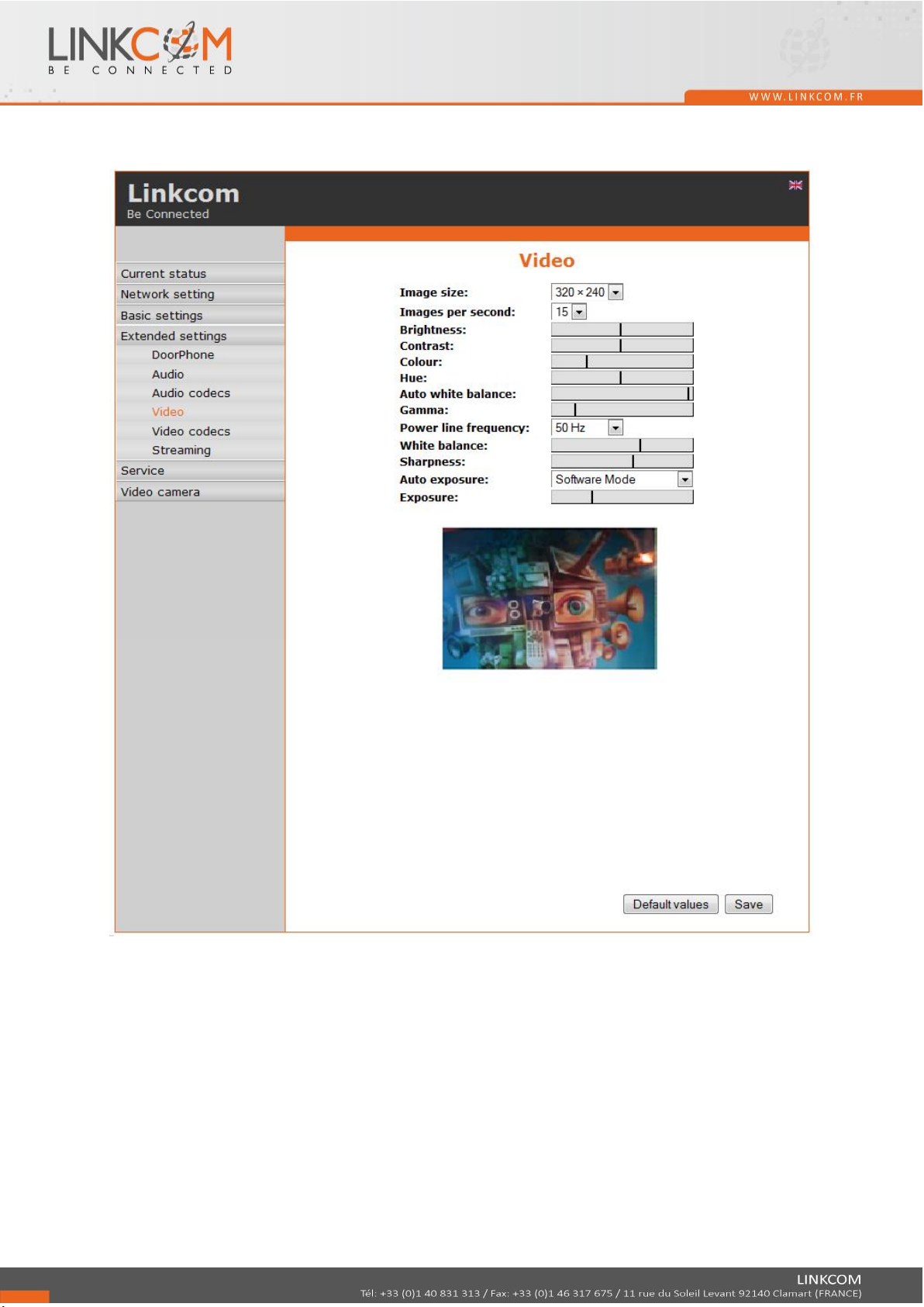
4.7.3 Video and video codecs settings
Image size: image size selection
Image number per second: this setting concern mainly image transmission to WEB browser.
Further setting: is standard image parameters setting and reset is immediately visible in Windows
screen.

32/80
32/40
Priority: setting of codecs priority for usage.
Compatibility: With some of VOIP phones manufactures you have to use in certain cases extra
setting:
- Yealink – phones Yealink
- SNOM – it is script sending for showing JPEG video. It is unique for SNOM phones

33/80
33/40
4.7.4 Streaming
Enable / disable to provide video (in H264) by the doorphone with protocol RTSP on port 554. To
receive such video you need some standard stream video players (IP TV or for example Grandstream,
MPlayer, VLC, etc…). This video running permanently. It’s not depending on calls.
Permitted IP address: when is not filled up then video might be watch by anybody. When is filled
then video is limited just for this IP address
Stream media: selection of what will be transmitted from RTSP server:
- video
- audio
- video and audio

34/80
34/40
Multicast address: by inserting IP address you allow sending RTP packets to selected multicasting
address.
JPEG image quality: you insert percentage of video coding quality
4.8 Service
4.8.1 Restart

35/80
35/40
4.8.2 Configuration
Save configuration: after click on “Make” button will be offered the place you can save the file
Load configuration: by click to empty button will allow to restore a saved configuration. Further is
necessary select if phone book, network setting, SIP and other parameters have to be loaded. By
clicking on “Make” button is loaded door entry setting from the file.
Clear phonebook: erase complete phonebook into default (all 999 possible items)
Default network and SIP: make default setting of network (IP address 192.168.1.250) and erase SIP
setting

36/80
36/40
Default others: all remaining parameters set to factory
By click on “Make” required settings will be done /erasing door entry parameters.
4.8.3 Style and language
Load Style file: by click to empty button select the file and by click on “Make” style file (symbols and
colors setting) is loaded.
Clean languages: it allows erase all added languages except factory languages

37/80
37/40
Load language file: by clicking on empty button select the file and by click on “Make” new language
file is loaded.
Save language file: after click on “Make” button will be performed language file export of just
selected language
4.8.4 Firmware upgrade
Choose firmware file: Select the firmware version and "Save".

38/80
38/40
4.8.5 Logfile
Start enhanced log: used to start or stop logs.
Download log file: Download debug log.
Show call log: Displays real-time recordings of SIP logs.
Show call log: Displays in real time all VoIP logs.

39/80
39/40
4.8.6 License
This page allows extend door entry features regarding payable functions via licenses. For example for
audio codec G729. After payment you’ll receive license number by email
License validity shows if license is working correctly. The license code is connected to serial number
of door entry.

40/80
40/40
4.8.7 User acoustic tones
This page is designed for recording own (user) sounds signaling. By clicking on “Play“ will be played
currently active sound file (selection is performed on page “Audio setting“ sound of relay closing on
page “Relays“).
Audio files: WAV – 8Kbit – mono – 16bit PCM
 Loading...