

Page 1
1
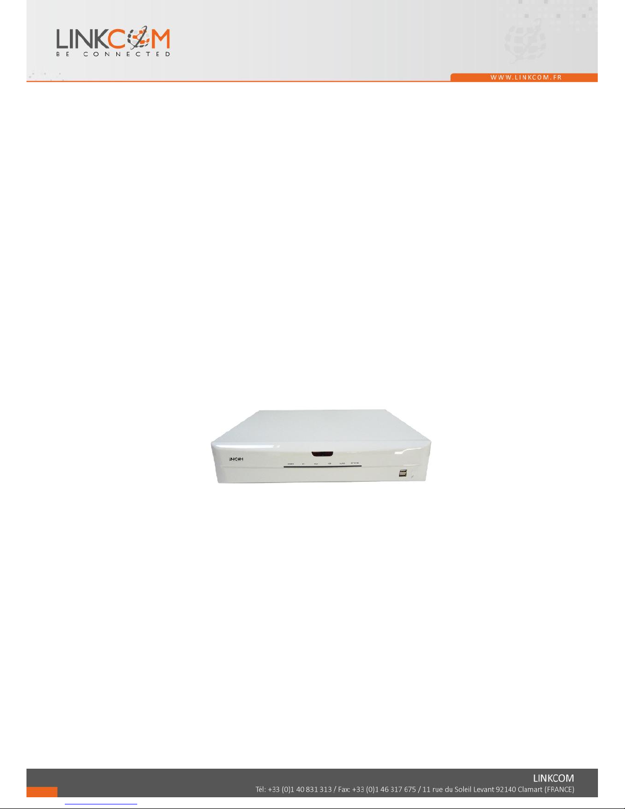
Link View NVR4
NVR 4 channels
User Guide
Please find the latest version of the manual and firmware at www.linkcom.fr
Page 2
2
HINSTRUCTION MANUAL
To obtain the best performance and ensure device function correctly, please read this instruction manual carefully and
completely.
FCC Compliance
USER-INSTALLER CAUTION: YOUR AUTHORITY TO OPERATE THIS FCC VERIFIED EQUIPMENT
COULD BE VOIDED IF YOU MAKE CHANGES OR MODIFICATIONS NOT EXPRESSLY APPROVED BY THE
PARTY RESPONSIBLE FOR COMPLIANCE TO PART 15 OF THE FCC RULES.
NOTE: THIS EQUIPMENT HAS BEEN TESTED AND FOUND TO COMPLY WITH THE LIMITS FOR A
CLASS A DIGITAL DEVICE, PURSUANT TO PART 15 OF THE FCC RULES. THESE LIMITS ARE
DESIGNED TO PROVIDE REASONABLE PROTECTION AGAINST HARMFUL INTERFERENCE WHEN THE
EQUIPMENT IS OPERATED IN A COMMERCIAL ENVIRONMENT. THIS EQUIPMENT GENERATES, USES,
AND CAN RADIATE RADIO FREQUENCY ENERGY AND IF NOT INSTALLED AND USED IN
ACCORDANCE WITH THE INSTRUCTION MANUAL, MAY CAUSE HARMFUL INTERFERENCE TO RADIO
COMMUNICATIONS.
OPERATION OF THIS EQUIPMENT IN A RESIDENTIAL AREA IS LIKELY TO CAUSE HARMFUL
INTERFERENCE IN WHICH CASE THE USER WILL BE REQUIRED TO CORRECT THE INTERFERENCE AT
HIS OWN EXPENSE.
THIS CLASS A DIGITAL APPARATUS MEETS ALL REQUIREMENTS OF THE CANADIAN
INTERFERENCE-CAUSING EQUIPMENT REGULATIONS.
WARNINGS, CAUTIONS & COPYRIGHT
WARINGS
TO REDUCE THE RISK OF FIRE OR ELECTRIC SHOCK, DO NOT EXPOSE THIS PRODUCT TO RAIN OR
MISTURE.
DO NOT INSERT ANY METALLIC OBJECT THROUGH VENTILATION GRILLS.
CAUTION
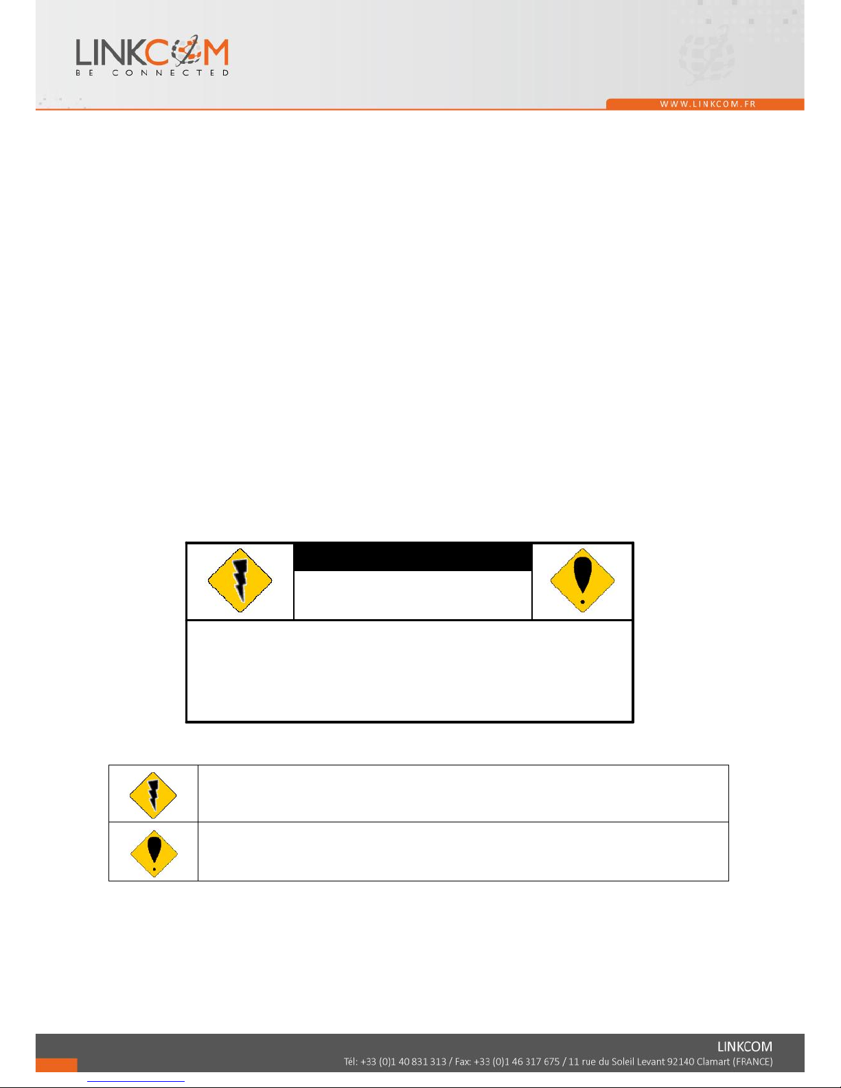
Explanation of Graphical Symbols
The lightning flash with arrowhead symbol, within an equilateral triangle, is intended to alert the
user to the presence of insinuated "dangerous voltage" within the products enclosure that may be of
sufficient magnitude to constitute a risk of electric shock to persons.
The exclamation point within an equilateral rhombus is intended to alert the user to the presence of
important operating and maintenance (servicing) instruction in the literature accompanying the
product.
USERS OF THE SYSTEM ARE RESPONSIBLE FOR CHECKING AND COMPLYING WITH ALL FEDERAL,
STATE, AND LOCAL LAWS AND STATUTES COIPCERNING THE MONITORING AND RECORDING OF
VIDEO AND AUDIO SIGNALS. LINKCOM SHALL NOT BE HELD RESPONSIBLE FOR THE USE OF THIS
SYSTEM IN VIOLATION OF CURRENT LAWS AND STATUTES.
COPYRIGHT
THE TRADEMARKS MENTIONED IN THE MANUAL ARE LEGALLY REGISTERED TO THEIR RESPECTIVE
COMPANIES.
CAUTION: TO REDUCE THE RISK OF ELECTRIC SHOCK.
DO NOT REMOVE COVER (OR BACK).
NO USER-SERVICEABLE PARTS INSIDE.
REFER SERVICING TO QUALIFIED SERVICE PERSONNEL.
RISK OF ELECTRIC SHOCK
DO NOT OPEN
CAUTION
Page 3

3
TABLE OF CONTENTS
1 INTRODUCTION...................................................................................................................................................4
1.1 FEATURE ................................................................................................................................................. 4
1.2 SPECIFICATION.....................................................................................................................................4
2 HARDWARE OVERVIEW................................................................................................................................... 8
2.1 FRONT PANEL........................................................................................................................................8
2.2 BACK PANEL ..........................................................................................................................................9
2.3 CAMERA & MONITOR LOOPING.................................................................................................... 10
2.4 ALARM TRIGGER................................................................................................................................ 10
2.6 PTZ (PAN, TILT AND ZOOM) CAMERA .......................................................................................... 12
3 SYSTEM SETUP ..................................................................................................................................................13
3.1 MENU SETUP INTERFACE(GUI)......................................................................................................13
3.2 LIVE VIEWING AND POP-UP MENU............................................................................................... 15
3.3 CAMERA SETUP...................................................................................................................................19
3.4 RECORD SETUP ...................................................................................................................................27
3.5 ALARM SETUP ..................................................................................................................................... 30
3.6 NETWORK SETUP ...............................................................................................................................34
3.7 AUTHORITY SETUP............................................................................................................................39
3.8 DISK MANAGEMENT.......................................................................................................................... 41
3.9 SYSTEM SETUP.................................................................................................................................... 43
3.EX DEBUG MESSAGE..................................................................................................................................46
4 NVR PLAYBACK................................................................................................................................................. 48
4.1 TIME SEARCH...................................................................................................................................... 49
4.2 EVENT SEARCH...................................................................................................................................49
4.3 BACKUP .................................................................................................................................................50
4.4 SYSTEM LOG........................................................................................................................................ 51
5 BACKUP PLAYBACK.........................................................................................................................................52
5.1 MAIN SCREEN SETTING ...................................................................................................................52
5.2 PLAYBACK OPERATION................................................................................................................... 55
6 NETWORK VIEWING & PLAYBACK ............................................................................................................ 59
6.1 IP ADDRESS SETUP ON PC SITE...................................................................................................... 59
6.2 OPTIONAL MICROSOFT INTERNET EXPLORER SETUP.........................................................61
6.3 LOGIN.....................................................................................................................................................63
6.4 REMOTE CONTROL............................................................................................................................ 64
6.5 CONFIGURE.......................................................................................................................................... 69
APPENDIX A: RECORDING TIME LAPSE (HOURS)............................................................................................ 83
APPENDIX B: HDD COMPATIBLE TABLE............................................................................................................. 84
APPENDIX C: ERROR MESSAGE LIST...................................................................................................................86
Page 4
4
1 INTRODUCTION
1.1 FEATURE
Support 4-channel IP cameras input.
Support H.264 / MJPEG decoding.
Real-time Display & Playback.
Support 5 Megapixel IP Camera for each channel.
Support HDDs x4
Support e-SATA interface
Support HDMI Video interface .
Audio Backup for all channels
Graphic User Interface ( GUI ).
Support time-point backup function under Ethernet remote control mode. User can
select any time period to process backup from remote side.
Support time-search & event-search function under Ethernet remote control mode.
Up to four online clients for independent remote control; individual live-time,
play-back & time-search function available
Support PPPoE/ Static/ DHCP IP & DDNS.
Powerful mobile surveillance function, support i-Phone & Android
1.2 SPECIFICATION
MODEL
4CH NVR
System
OS
Embedded Linux
connector
Ethernet
RJ-45, 10/100/1000 Mbps x1
VGA
output
D-SUB output
HDMI
output
HDMI output
USB 2.0
Front : 2 ports
Power
DC-12V, 5A
Video and Audio
Video input
4 channels
Audio input
4 channels
NVR Functions
Camera Name
Max. 20 characters
Screen Split Control
1, 4,
Image Control
Contrast / Brightness / Saturation / Hue
Page 5

6
Recording mode
Manual / Schedule / Alarm
Pre Recording
1~5 sec
Watermark
Support
Searching and Playback
Search Method
Date / Time / Event
Date/ Time / Event Search
Selectable on the calendar
Log Search
Through the log data to find the video event / time
Backup Type
USB
Remote Client Software
Monitoring Environment
Link View for iPhone / iPad /Android, Web site
IP cam Live View
4 Channels
Remote Search
Web site remote time / event search
System Monitoring and Recovery
Monitoring
Watchdog
Alarm
Alarm Input
4 inputs
Alarm output
1 outputs
Peripheral Devices
Audio in
3.5 Ø Earphone stereo jack
Audio out
3.5 Ø Earphone stereo jack
RS 485
2- pin terminal
STORAGE & BACKUP DEVICE
INTERNAL HDD SUPPORT
SATA HDD x 4
EXTERNAL USB BACKUP
DEVICE
(PAN DRIVE, HDD,
BURNER)
USB x2
E-SATA
x1
RAID
N/A
Networking
Type
Static/ DHCP/ PPPoE/DDNS
Environment
Operating Temp.
0 - 45 ℃ / 32~113 F
Humidity
0~80% RH (non-condensing)
Page 6
7
Language
Type
English / Traditional Chinese / Simple Chinese / Russian / Italian
/ Japanese / Czech / France / Germany / Spanish / Portuguese
Physical
Dimensions (W x H x D)
360 x 60 x 311 mm
Weight
4 KG
* SPECIFICATIONS ARE SUBJECT TO CHANGE WITHOUT NOTICE
Page 7
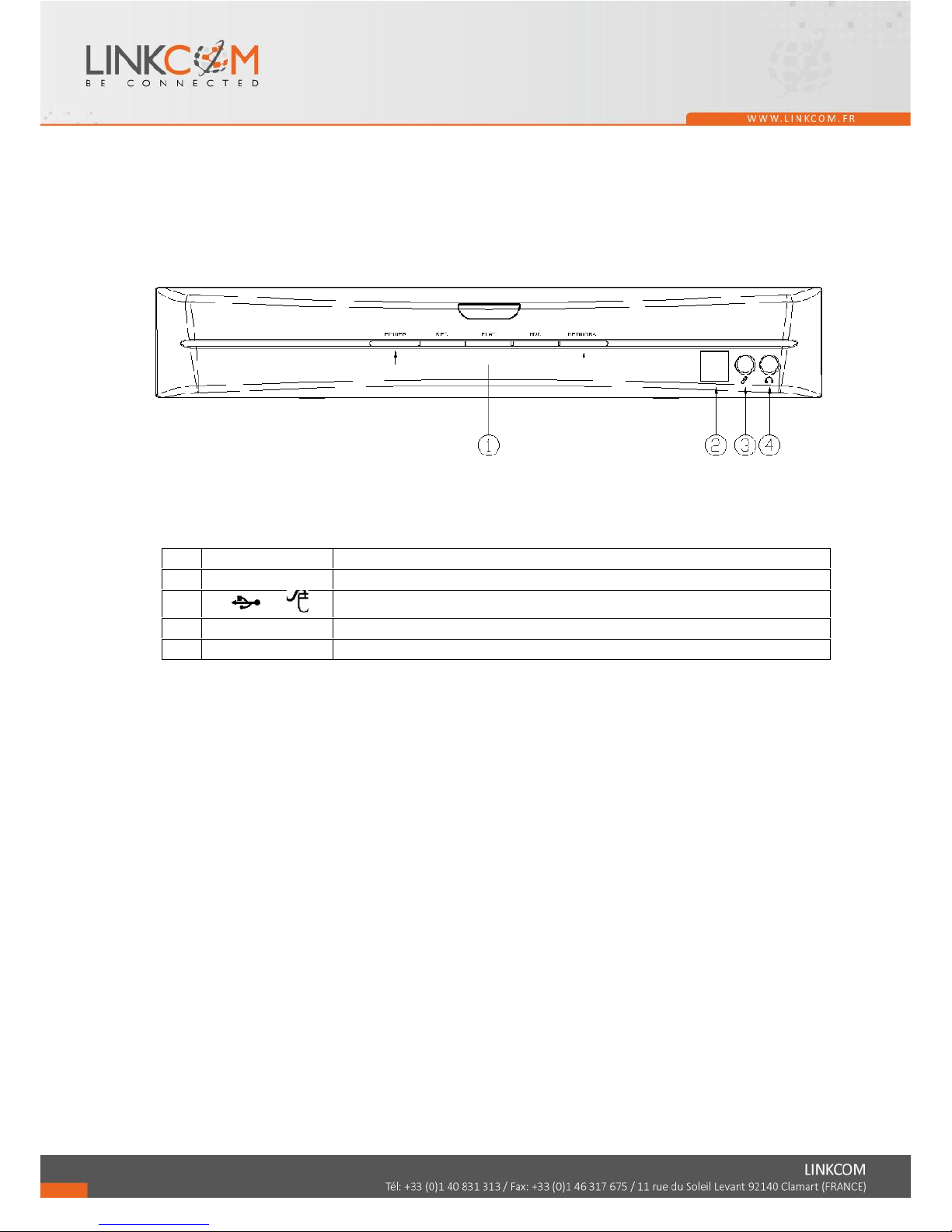
2 HARDWARE OVERVIEW
2.1 FRONT PANEL
NVR OPERATION
NO.
LABEL
OPERATION
1
LED
Led Indicator
2
/
USB Connector/ USB Mouse Connector
3
MIC IN
Microphone input(Phone Jack)
4
AUDIO OUT
Earphone output(Phone Jack)
4321
76 8
10 11 12
22
OPERATION
Led Indicator
USB Connector/ USB Mouse Connector
Microphone input(Phone Jack)
Earphone output(Phone Jack)
8
Page 8
9
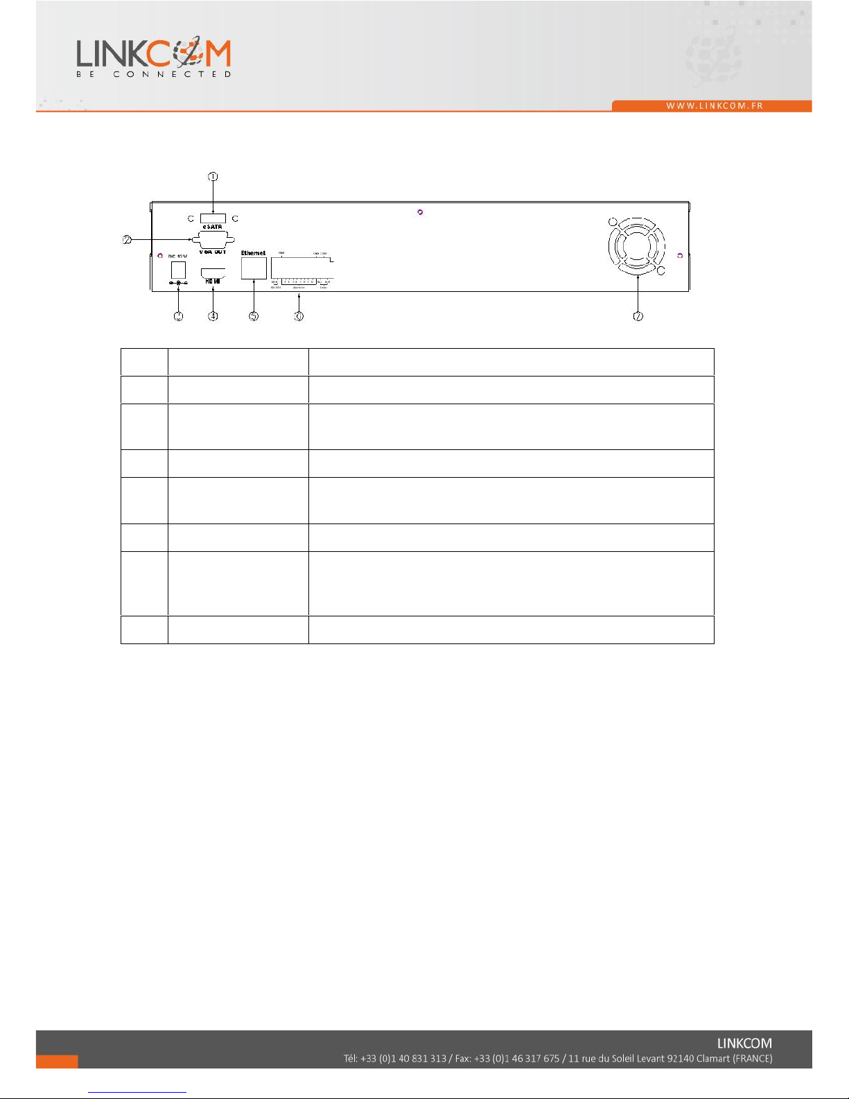
2.2 BACK PANEL
NO.
LABEL
OPERATION
1
E-SATA
E-SATA interface
2
VIDEO OUT
(VGA)
Connect to LCD monitor
3
POWER
Connect to power adapter (AC 12V/5A)
4
VIDEO OUT
(HDMI)
HDMI video output
5
ETHERNET
RJ-45 connector
6
ALARM IN/
RELAY OUT/
RS-485
8 alarm in/ 1 relay out/ RS485
7
FAN
The fan louvers
Page 9
10
2.3 CAMERA & MONITOR LOOPING
Here recommend link cameras by sequence to avoid unexpected image broken, from CH1,
CH2, CH3, CH4…….
2.4 ALARM TRIGGER
There are four types of alarms: Motion detection, Video Loss Alarm, External Alarm, and
Digital Input from Camera. Following are the possible action when alarm is triggered.
Every action is configurable (Ex. the screen display pattern, the buzzer triggered time.etc)
and will be explained in the later chapter.
A. When Motion detection happens:
a. The live screen pattern can be switch to single channel screen or split screen.
b. Built-in buzzer or external relay can be triggered.
c. Alarm timepoint can be recorded in the event list, and you can search for the event
in playback.
d. On the channel which the alarm triggered, the icon pops up to remind the user.
e. The pre/ post-alarm recording video can be sent to e-mail/ uploaded to FTP.
f. CGI can be sent to an http server.
B. When External Alarm or Digital Input from Camera happens:
a. Built-in buzzer or external relay can be triggered.
b. Alarm timepoint can be recorded in the event list, and you can search for the event
in playback.
c. On the channel which the alarm triggered, the icon pops up to remind the
user.
d. The pre/ post-alarm recording video can be sent to e-mail/ uploaded to FTP.
e. CGI can be sent to an http server.
C. When Video Loss Alarm happens:
a. Built-in buzzer or external relay can be triggered.
b. Alarm timepoint can be recorded in the event list, and you can search for the event
in playback.
c. On the channel which the alarm triggered, the icon pops up to remind the
user.
d. CGI can be sent to an http server.
Page 10
11
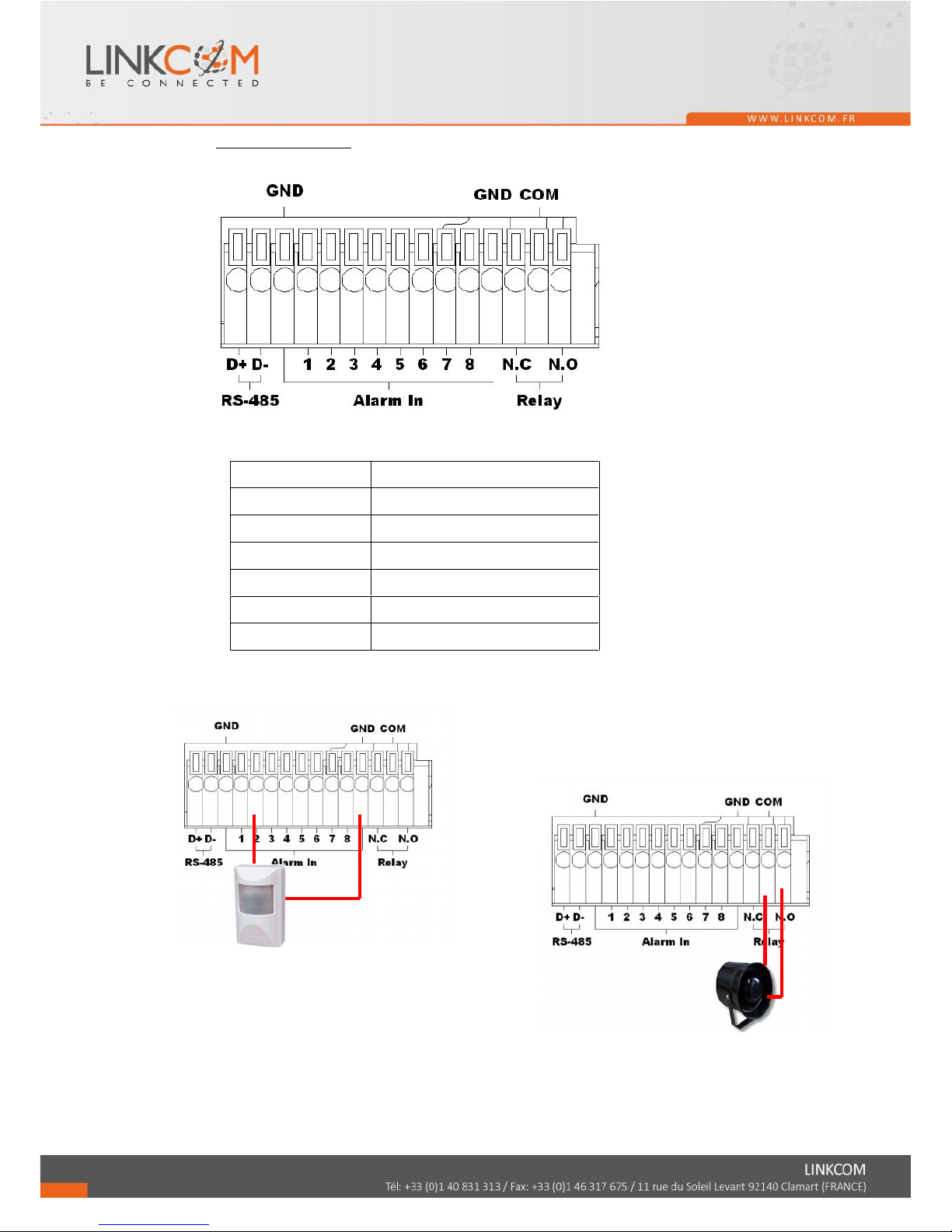
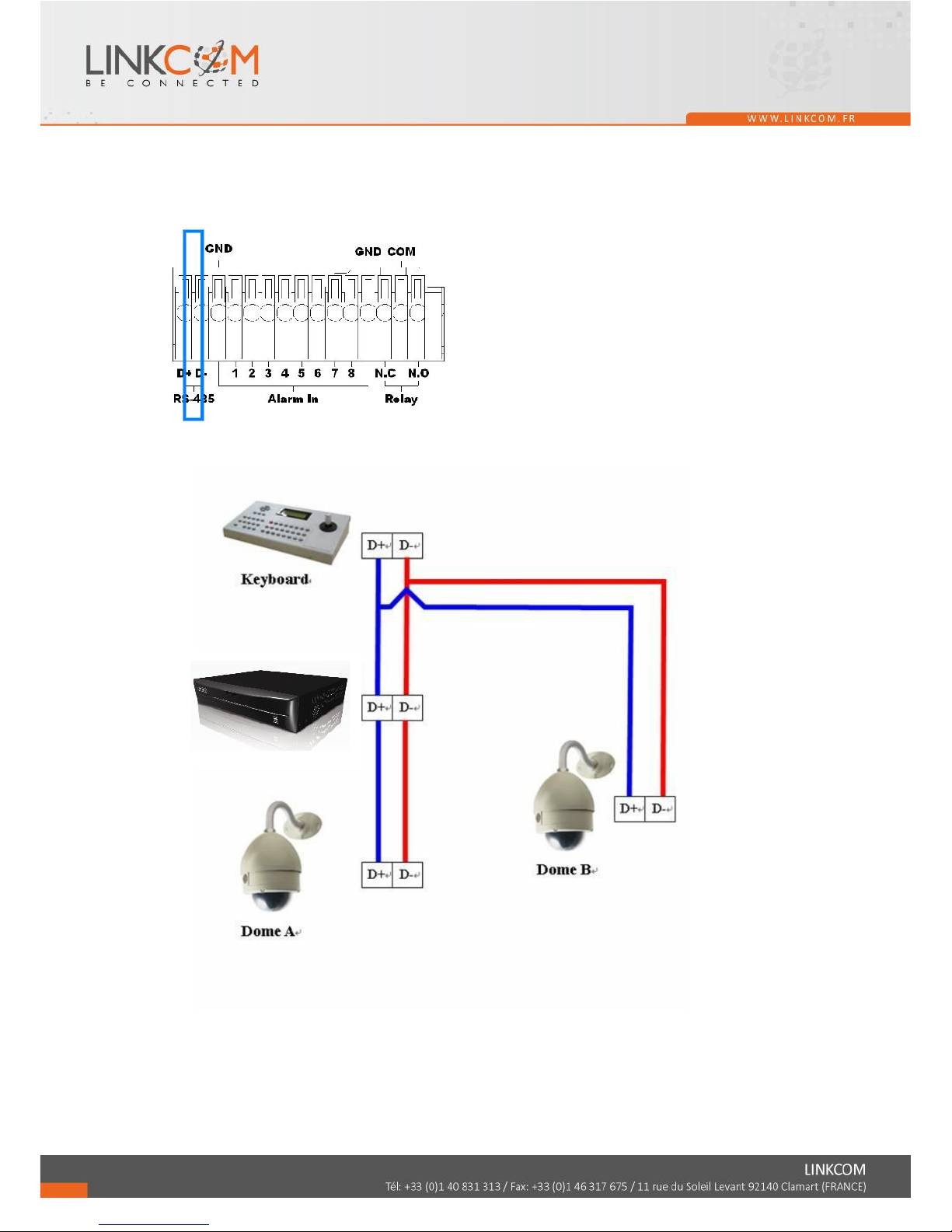
D. Alarm in connecter
EX1:Connect GND & Alarm to external IR detector.
EX2:Connect N.O & COM to external siren.
Depending on the external device type,
You may connect N.C & COM to external device.
D+
RS-485: sends +/ receives +
D -
RS-485: sends -/ receives -
GND
Ground
ALARM IN 1-8
Alarm input
N.C
Relay: Normally close
N.O
Relay: Normally open
COM
Relay: Common
Page 11
12
2.6 PTZ (PAN, TILT AND ZOOM) CAMERA
Following diagram for NVR connect between PTZ camera & joystick controller, for NVR to
control PTZ camera please make sure the CAMERA ID, BANDRATE (default at 9600 bps)
and RS-485 cable.
Under “Two Core” connection, controller can control speed dome without integrated protocol
into NVR. Moreover, one keyboard can connect MAX 256 units of speed dome.
Page 12
13
3 SYSTEM SETUP
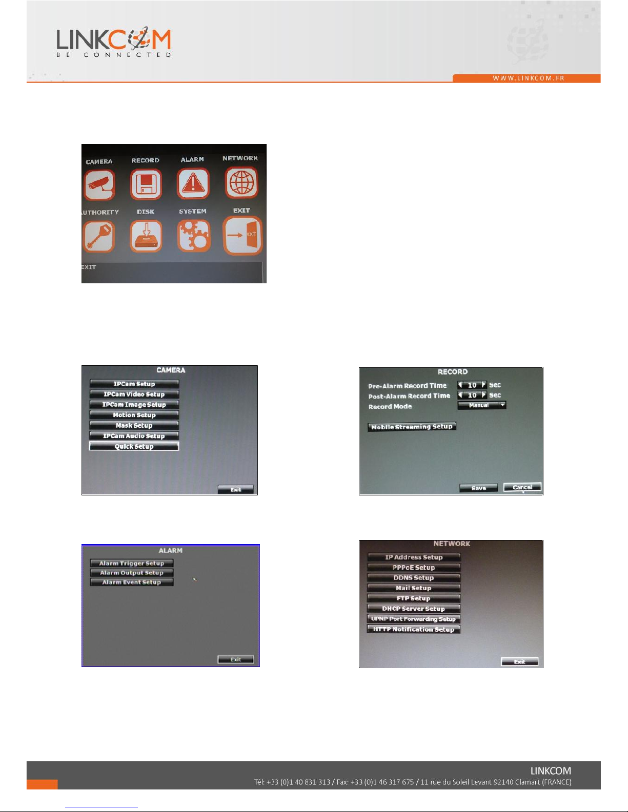
3.1 MENU SETUP INTERFACE(GUI)
A. CAMERA SETUP B. RECORD SETUP
C. ALARM SETUP D. NETWORK SETUP
Page 13
14
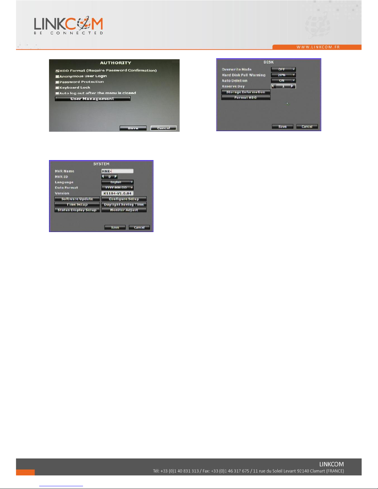
E. AUTHORITY SETUP F. DISK MANAGEMENT
G. SYSTEM SETUP H. EXIT
Page 14
15
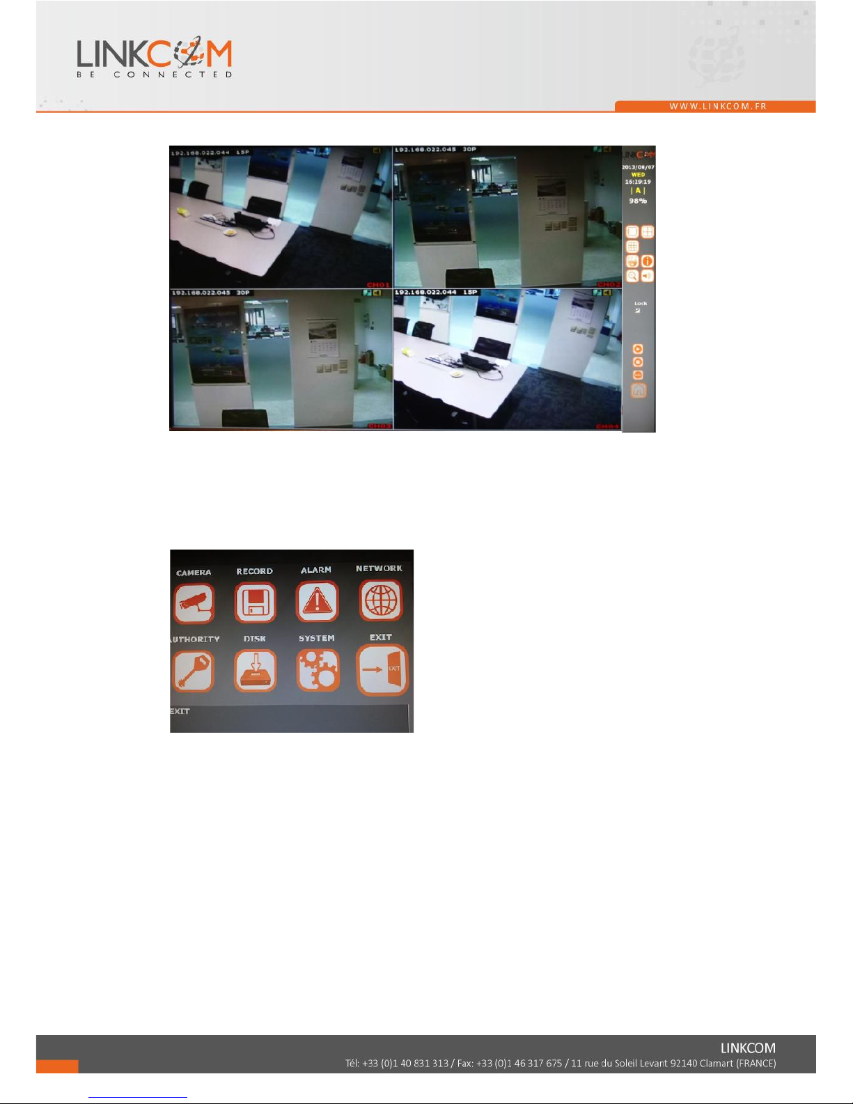
3.2 LIVE VIEWING AND POP-UP MENU
NOTE:The pop-up menu can be activated by moving the mouse cruise to the bottom
of the live viewing screen.
A. GUI MENU BAR
With live viewing mode, press this button to get into the GUI menu.
B. DISPLAY CONTROL
Within live-viewing or playback mode, use display control to switch the camera
channel.
C. AUTO SWAP
Press it to start auto swap. The interval depends on the setting in IPCam Image Setup
when it’s on single channel view. For split screen the switch dwell interval is 5 sec.
D. PTZ CONTROLLER
Within live-viewing mode, Clicks this button to get into the PTZ setup menu. User can
right-click the button of the mouse to exit PTZ Setup.
NOTE: Only for the camera supported PTZ function.
Page 15
16
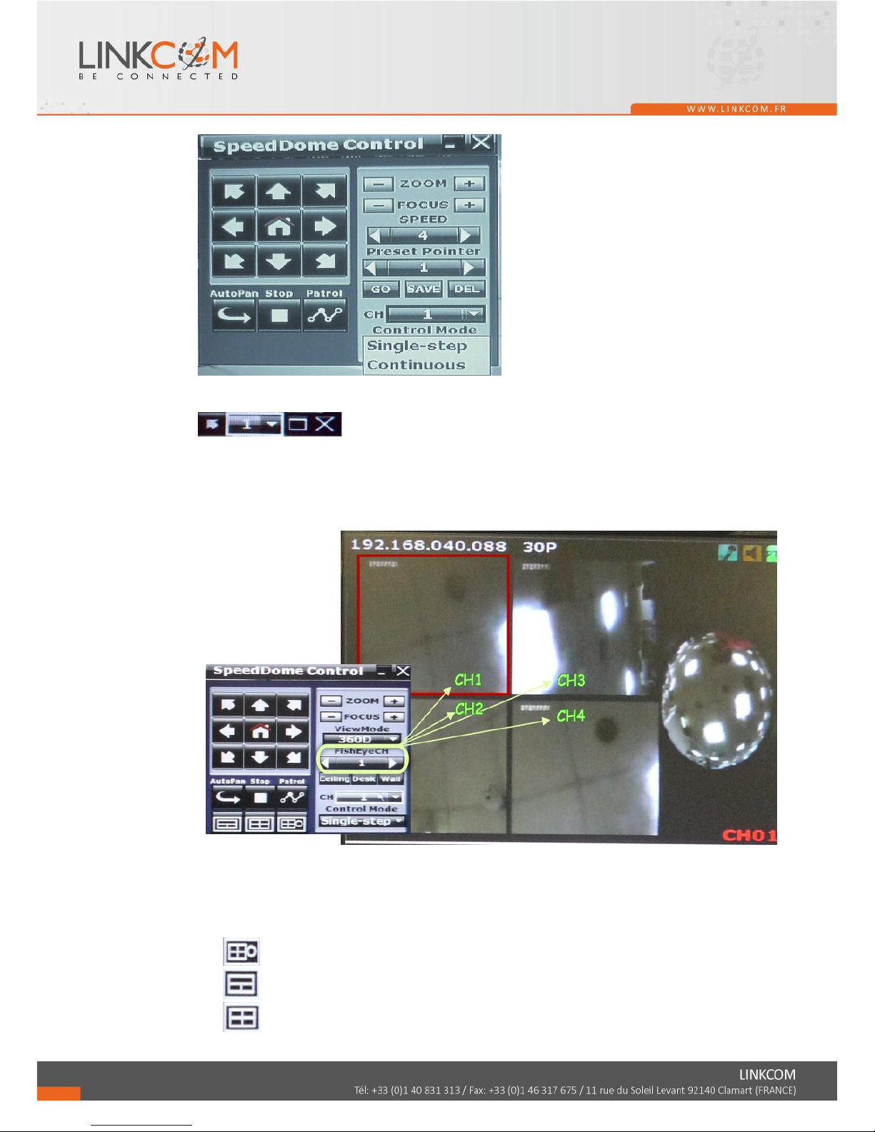
PTZ CONTROL
Press the minimization icon then the control panel becomes smaller:
Move the mouse and the arrow will follow the mouse and change direction. In this
mode user can click on the live view to control direction instead of the direction key
on control panel.
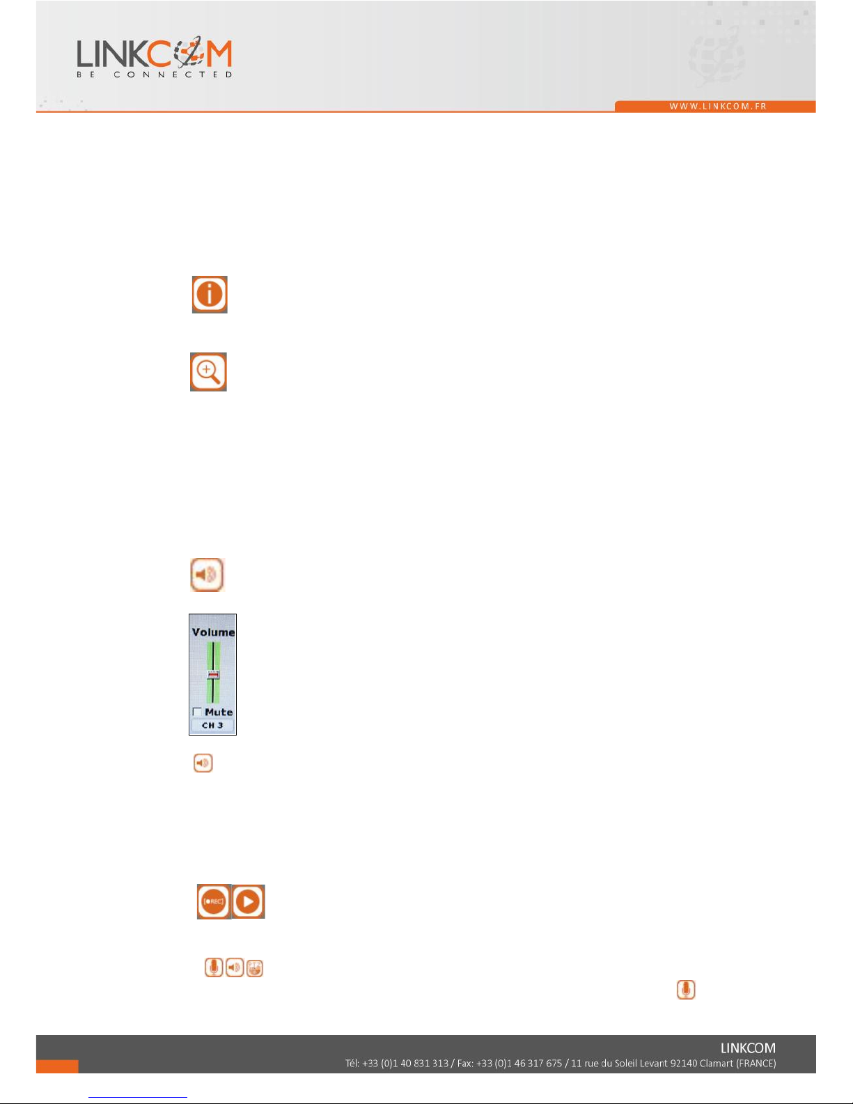
If a fisheye camera is connected:
E-PTZ Steps:
(1) Select the channel number you want to setup, if there are several ones.
(2) Select the View Mode, 360 degree or 180 degree.
(3) Select the camera location, ceiling, desk, or wall.
(4) Select split screen pattern
: 360 degree panorama view + sub screens x4
: 180 degree flat view + sub screens x2
: sub screens x4
Page 16
17
(5) After you decide the screen pattern, use the fisheye channel list to select one of the
sub screens. (as the green circle on the picture above). The selected one will be
indicated in a red frame.
(6) For the selected sub screen, use the 4-direction arrows and the “+” (zoom in) ”-”
(zoom out) icon for E-PTZ control.
(7) Control Mode: Select the E-PTZ moving mode, step by step or continuous.
(8) The AutoPan, Stop, and Patrol buttons are invalid here if the fisheye camera
doesn’t support those function.
E. DISK INFORMATION
With live viewing mode, press this button to display disk information.
F. DIGITAL ZOOM
In the live full screen mode, left-click the button of the mouse to pull a range to zoom
in or zoom out the image. User can right-click the button of the mouse to disable this
function. (NOTE: Using the mouse to operate digital zoom can zoom in to max. 16
times.) Moreover, user can also use ZOOM key on the front panel to perform this
function. (First, click ZOOM Key and then click ▲▼◄► key to select zoom in or
zoom out position. Finally, click ENTER key to complete the setting. Moreover, click
ZOOM Key again can disable digital zoom function. Using the panel key to perform
zoom in function is fixed at 2 times.)
G AUDIO VOLUME
Press this button, and the audio volume control board will pop up.
H. BOARDCASTING
Press the bottom to enable or disable the one way audio. You can use microphone to
speak simultaneously to all the channels.
I. FULL SCREEN
Press the bottom for full-screen mode.
J. RECORD AND PLAYBACK CONTROL
Same as front panel controller and remote controller.
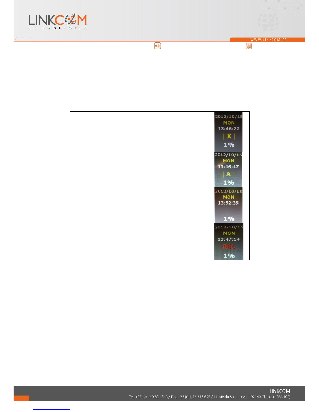
K. SOUND INPUT/ SOUND OUTPUT / PTZ CONTROL
There are little icon on the right top of the live vide of every channel. Click to
Page 17
18
enable the two ways audio. Click to enable the sound output. Click to PTZ
call out the control board. Note that if those functions are not support by the camera
linked, you will not see the corresponding icons.
The sound options do not affect the audio recorded into playback video. As long as the
audio setup is enabled, the playback video includes audio even the sound output here
is turned off.
L. RECORDING STATUS
Beneath the date and time, it displays the current recording type:
Record mode: Schedule – NO REC period
Record mode: Schedule – ALARM REC period
Record mode: Alarm trigger
Record mode: Manual – Stop Recording
Record mode: Schedule – FULL REC period
Record mode: Manual – Recording
Page 18
19
3.3 CAMERA SETUP
A. IPCam Setup
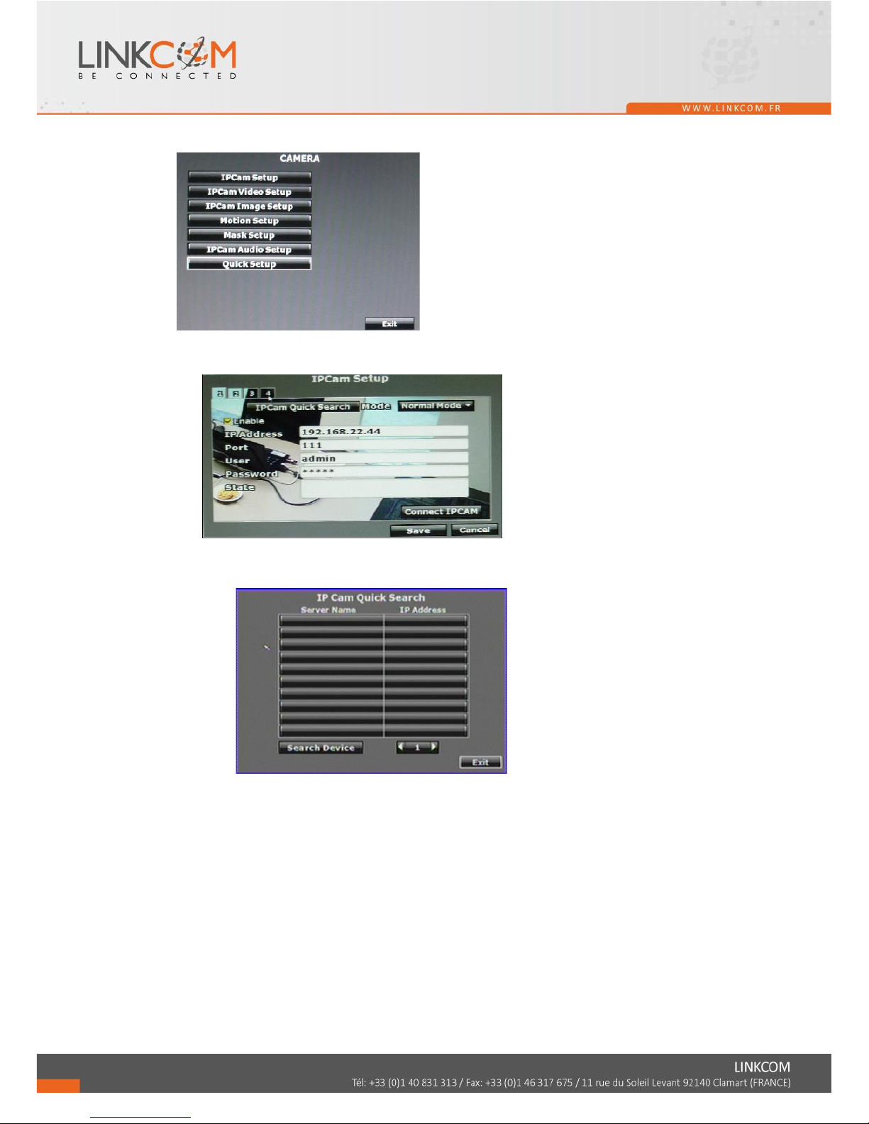
A-1. IPCam Quick Search
NVR can search for the IP devices under the same domain with NVR.
Click the IPCam in the list to add it to NVR channel.
If you want to revise the IP setting of a camera, click “Edit”:
The IPCam has to be under the same LAN with NVR in order to connect
successfully. Ex. If NVR IP address is 192.168.10.33, IP Cam IP address should
be 192.168.10.X. You can edit IP Cam IP address here or on the IP Cam.
Page 19
20
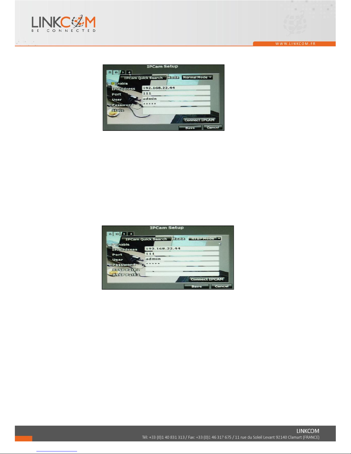
a. Normal Mode
Enable this channel. Key in the IP address, port, username, and password of
the device you prepare to connect. You can find the information on the IP
Cam.
Click the “connect IPCAM” button, the message will show in “State” column
to tell you whether connection succeeds or not.
Note: To the camera connected via ONVIF protocol, the PTZ control
function is not supported.
b. RSTP Mode
Under RTSP Mode, the NVR only support the IP address indication, the live
video, and video recording. Other functions like motion detection are not
supported.
Key in the IP address, port, username, and password of the device you
prepare to connect. You can find the information on the IP Cam.
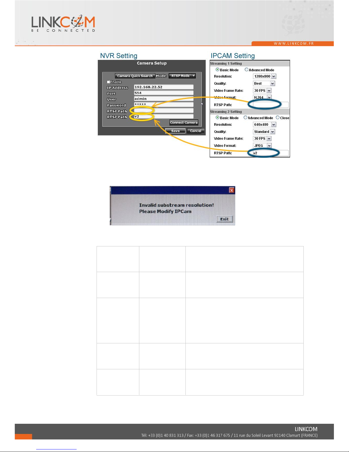
To link to the IP camera, check the RTSP Path settings of your IP camera,
and key in the corresponding values of two streams in “RTSP Path 1” and
“RTSP Path 2”.
Page 20
21
Note: When you select RTSP mode, make sure the substream resolution of
camera is VGA(640x480). Or you will receive the warning message when
you try to connect with the camera:
Here we lists some RTSP setting for sample:
RTSP Path 1
(IPCam Main
stream)
RTSP Path 2
(IPCam Sub
stream)
Result
1920 x 1080
640 x 480
OK.
NVR takes 1920x1080 streaming for single
channel view, and 640x480 streaming for
split screen.
1920 x 1080
N/A
(Fill in nothing
on "RTSP Path
2")
Error Message: ”Invalid Substream
Resolution! Please modify IPCam.”
NVR takes 1920x1080 streaming for both
single channel view and split screen.
However, it can only allow 640x480
resolution for split screen, so it shows error
in return.
640 x 480
N/A
(Fill in nothing
on "RTSP Path
2")
OK.
NVR takes 640x480 streaming for both
single channel view and split screen.
N/A
(Fill in
nothing on
"RTSP Path 1")
640 x 480
OK.
NVR takes 640x480 streaming for both
single channel view and split screen.
Page 21
22
640 X480
1920 x 1080
OK.
NVR takes 1920x1080 streaming for single
channel view, and 640x480 streaming for
split screen.
1920 x 1080
1920 x 1080
Error Message: ”Invalid Substream
Resolution! Please modify IPCam.”
NVR takes 1920x1080 streaming for both
single channel view and split screen.
However, it can only allow 640x480
resolution for split screen, so it shows error
in return.
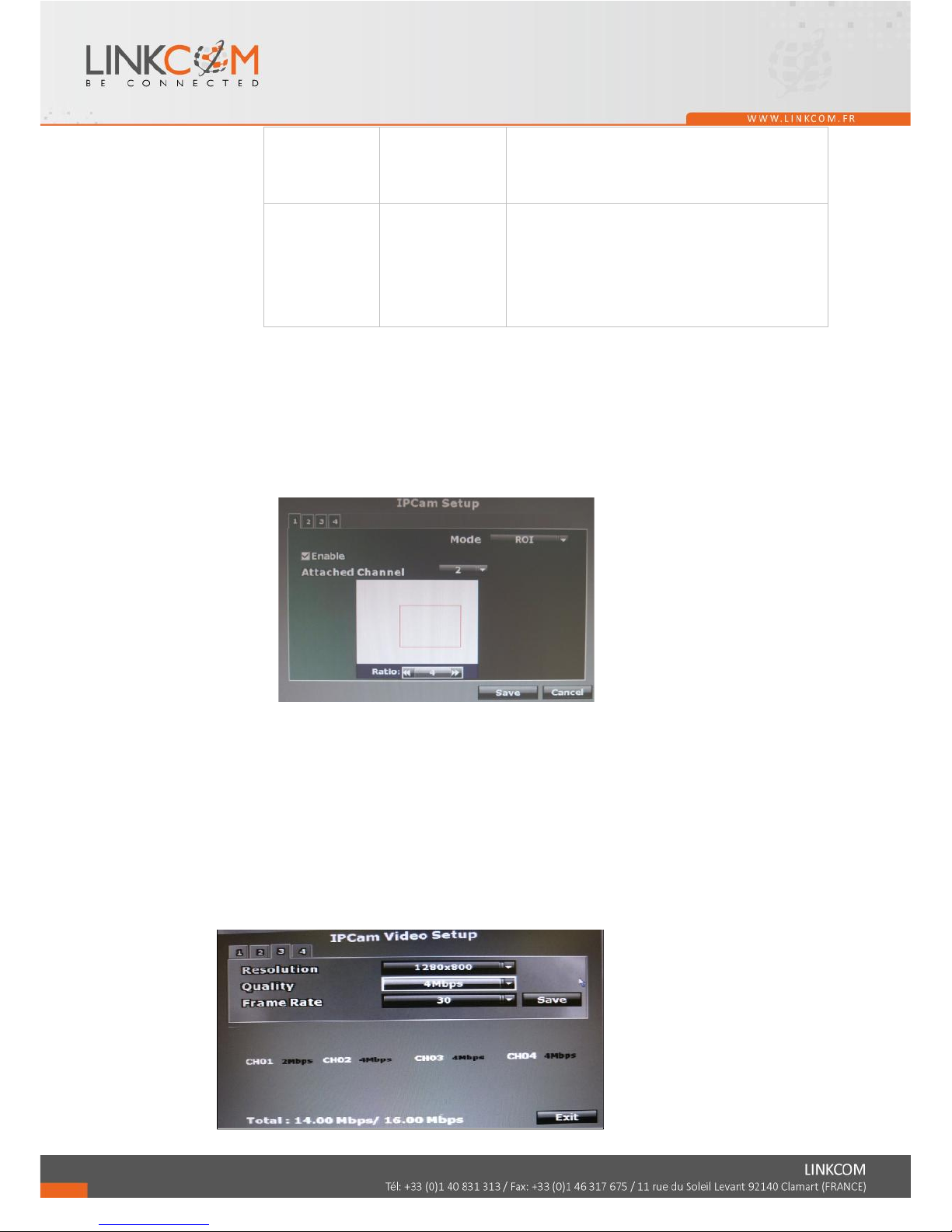
c. ROI
This function allows users to set up the channel as an attached channel. An
attached channel is based on a normal/ RTSP channel has been set up, and
can display the same live view as the normal/ RTSP channel. The attached
channel is not physically linked to any camera, so it doesn't increase the
bandwidth loading. Users cannot do camera setup (like motion detection or
image adjustment) on attached channel.
1. Enable: Choose “ROI”.
2. Attached Channel: Select a connected normal/ RTSP channel in the
drop-down menu.
3. Ratio: Use the arrows to adjust the zoom ratio, and press the red frame to
drag it to the area that you want it to show on the live view screen.
A-2. Connect IPCAM:After insert the IPCAM related information, click this button
to test the connection circumstances.
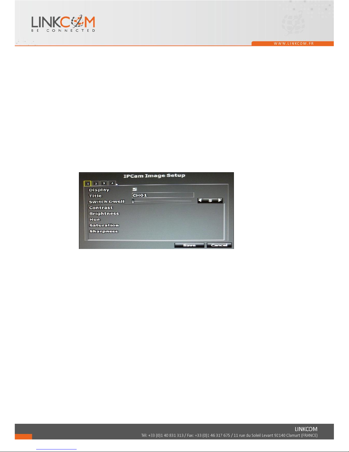
B. IPCam Video Setup
Page 22
23
B-1. Resolution
Click drop down list to change the resolution of connecting device.
B-2. Quality
Click drop down list to change the image quality.
For H.264 IPCam above 1 Megapixel, the resolution options support “4Mbps,
3Mbps, 2Mbps, 1.5Mbps, 1Mbps”.
For H.264 IPCam less than 1 Megapixel, the resolution options support” 2Mbps,
1.5Mbps, 1Mbps, 512Kbps, 256Kbps”
For MPEG IPCam, the resolution options support “Standard, Medium, Low”.
(The highest resolution option is “standard” due to the chip performance limits
of IPCam)
B-3. FrameRate
Click drop down list to change the frame rate of connecting device.
C. IPCam Image Setup
C-1. Display
Use the mouse to enable or disable the camera display on the screen or not.
C-2. Title
Use the mouse to setup the title of connecting IP device.
C-3. Switch Dwell
Press ◄ or ► to change auto switch second. The value is between 0~99 sec.
C-4. Contrast
Press ◄ or ► to change contrast level. The adjustment value is between 0~255
C-5. Brightness
Press ◄ or ► to change brightness level. The adjustment value is between
0~255
C-6. Hue
Press ◄ or ► to change hue level. The adjustment value is between 0~255
C-7. Saturation
Press ◄ or ► to change saturation level. The adjustment value is between
0~255
C-8. Sharpness
Press ◄ or ►/ mouse wheel to change sharpness level. The adjustment value is
between 0~15
Page 23
24
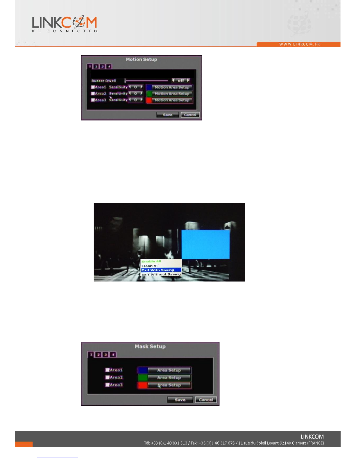
D. Motion Setup
D-1. Buzzer Dwell
Press ◄ or ► to change the buzzer time or disable buzzer function.
D-2. Area1 Sensitivity
Press ◄ or ► to change the sensitivity of setup motion area in Area1. Click
“Motion Area Setup” and drag a blue area for motion detection.
D-3. Area2 Sensitivity
Press ◄ or ► to change the sensitivity of setup motion area in Area2. Click
“Motion Area Setup” and drag a green area for motion detection.
D-4. Area3 Sensitivity
Press ◄ or ► to change the sensitivity of setup motion area in Area3. Click
“Motion Area Setup” and drag a red area for motion detection.
After dragging an area, right-click the mouse, select “Exit with saving” to
complete the area setup.
Select “Enable All” to set up global motion detection.
Select “Clean All” to clean the area of the current color in the view.
Select “Exit Without Saving” to go back to motion setup menu and the setting
you just changed will not be saved.
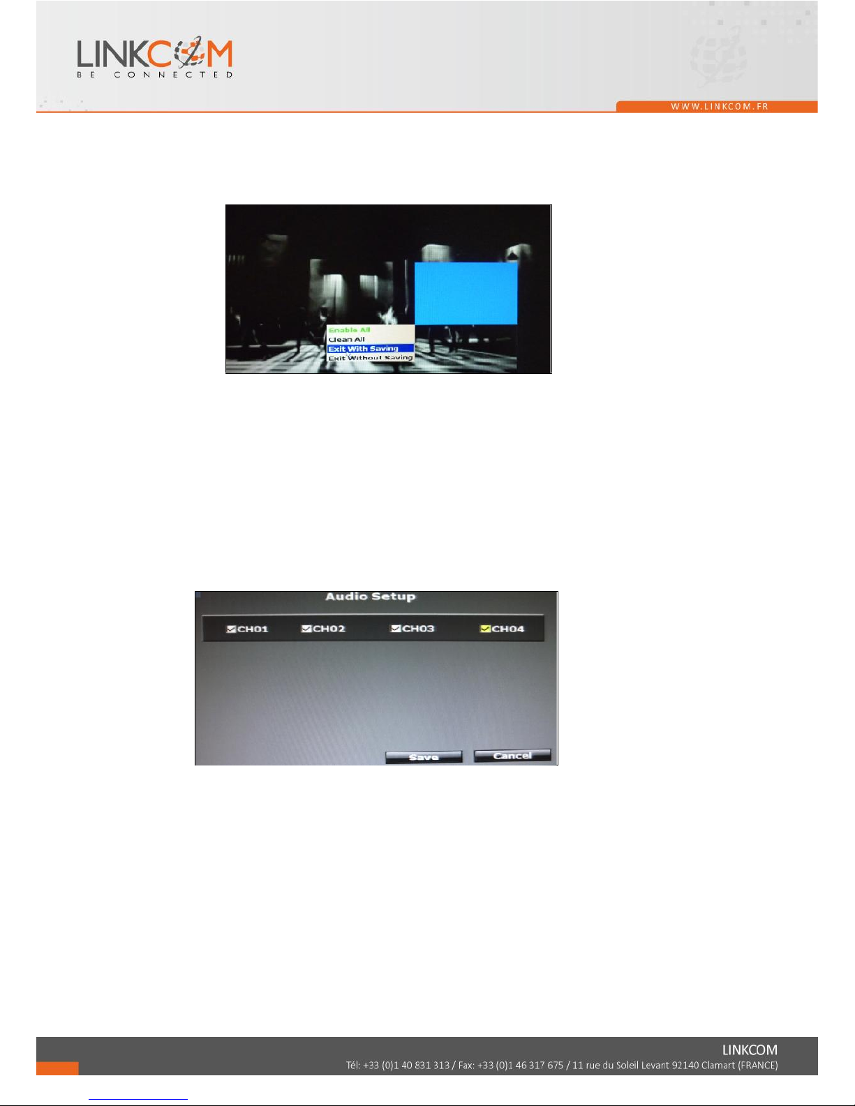
E. Mask Setup
The masked area will not show on the live video and video playback.
E-1. Area1
Page 24
25
Tick the “Area1” box and click “Area Setup” to drag a blue area for masking.
E-2. Area2
Tick the “Area1” box and click “Area Setup” to drag a green area for masking.
E-3. Area3
Tick the “Area1” box and click “Area Setup” to drag a red area for masking.
After dragging an area, right-click the mouse, select “Exit with saving” to
complete the area setup.
Select “Enable All” to set up global masking.
Select “Clean All” to clean the area of the current color in the view.
Select “Exit Without Saving” to go back to mask setup menu and the setting you
just changed will not be saved.
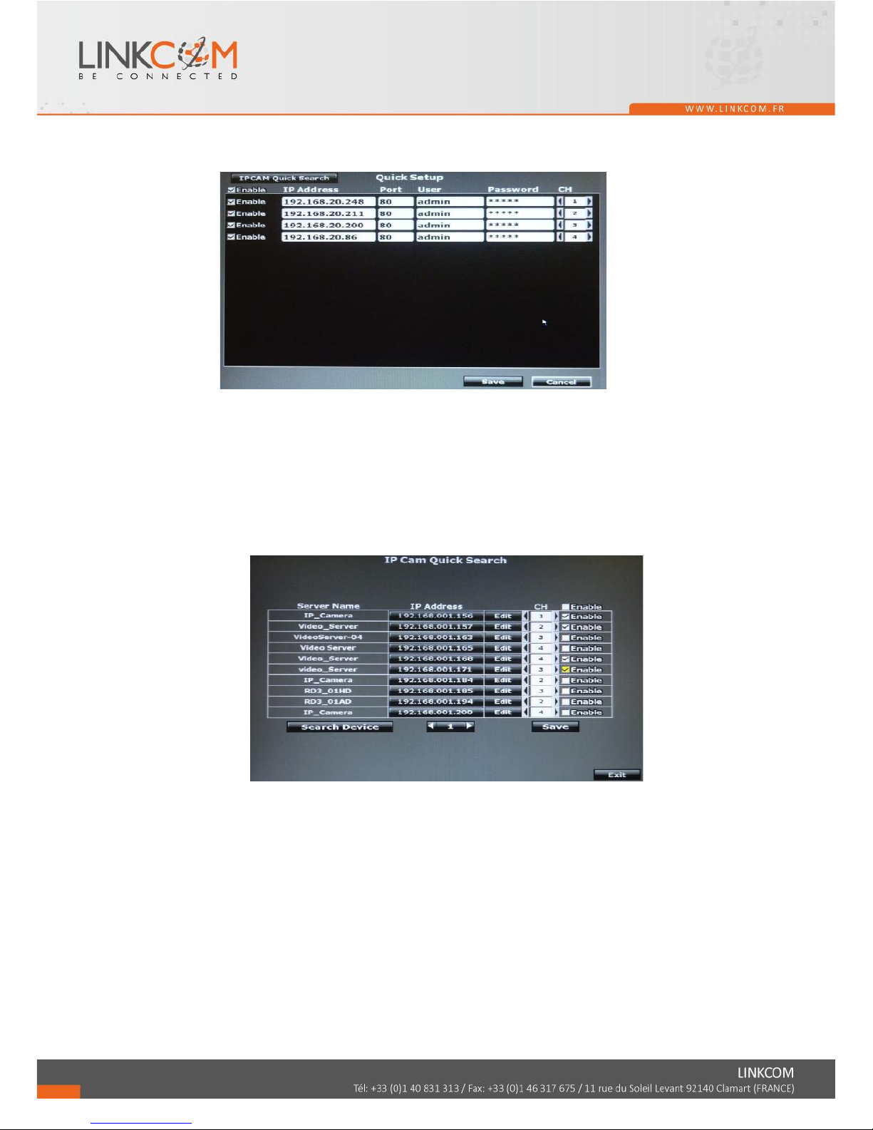
F. Audio Setup
The channel ticked means the sound from camera will be recorded into the playback
video. Vise versa. No sound will be recorded in the playback video of the channel
which is not ticked.
Page 25
26
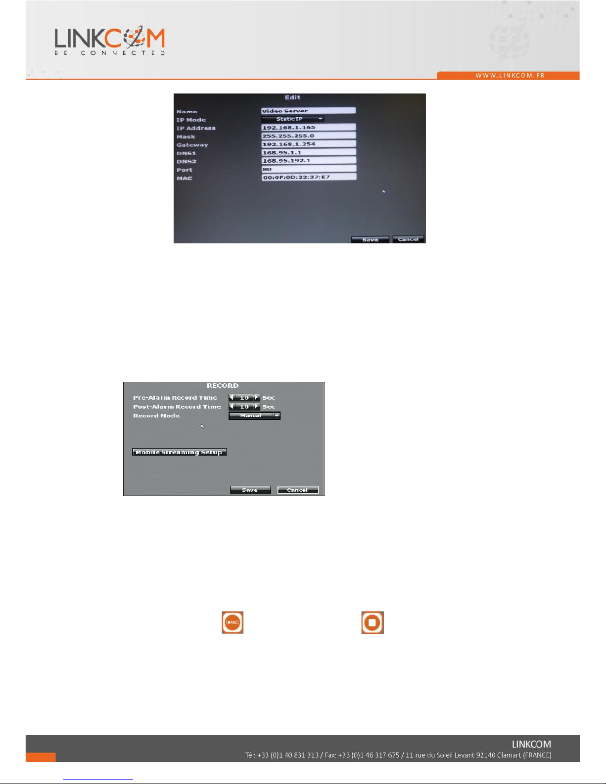
G. Quick Setup
Other than “IPCAM Setup”, you can choose another way to complete the IP camera
connection job: using Quick Setup.
G-1 Key in information manually
Here is the all-channel list. You can key in the IP address, port, and user name
& password of the IP camera, and then assign the channel number. Tick
“Enable” to connect with the IP camera.
G-2 IPCAM Quick Search
With Quick Search, you need not type the IP address. Click “IPCAM Quick
Search” to enter the search menu.
The machine searches for all the IP devices under the LAN and list here. Find
the IP camera you want to connect with, assign a channel number for it, and
tick “Enable” so that this IP camera will be added to the all-channel list.
Back to the all-channel list, you can key in the user name and password, and
tuck “Enable” to connect with the camera.
If you want to revise the IP setting of a camera, click “Edit”:
Page 26
27
The IPCam has to be under the same LAN with NVR in order to connect
successfully. Ex. If NVR IP address is 192.168.10.33, IP Cam IP address
should be 192.168.10.X. You can edit IP Cam IP address here or on the IP
Cam.
3.4 RECORD SETUP
A. Pre-Alarm Record Time / Post-Alarm Record Time
Pre-alarm record means the recording before alarm is triggered; post-alarm record
means the recording after alarm is triggered. If you set 5 sec for pre-alarm and 5 sec
for post-alarm, the alarm recording length will be total 10 sec.
B. Record Mode
The record mode will be applied to all channels simultaneously. When recording,
NVR record both main streaming and sub streaming from IPCam.
Use the drop down list to switch the recording mode.
1. Manual: Click to start recording. Click to stop recording.
2. Schedule:
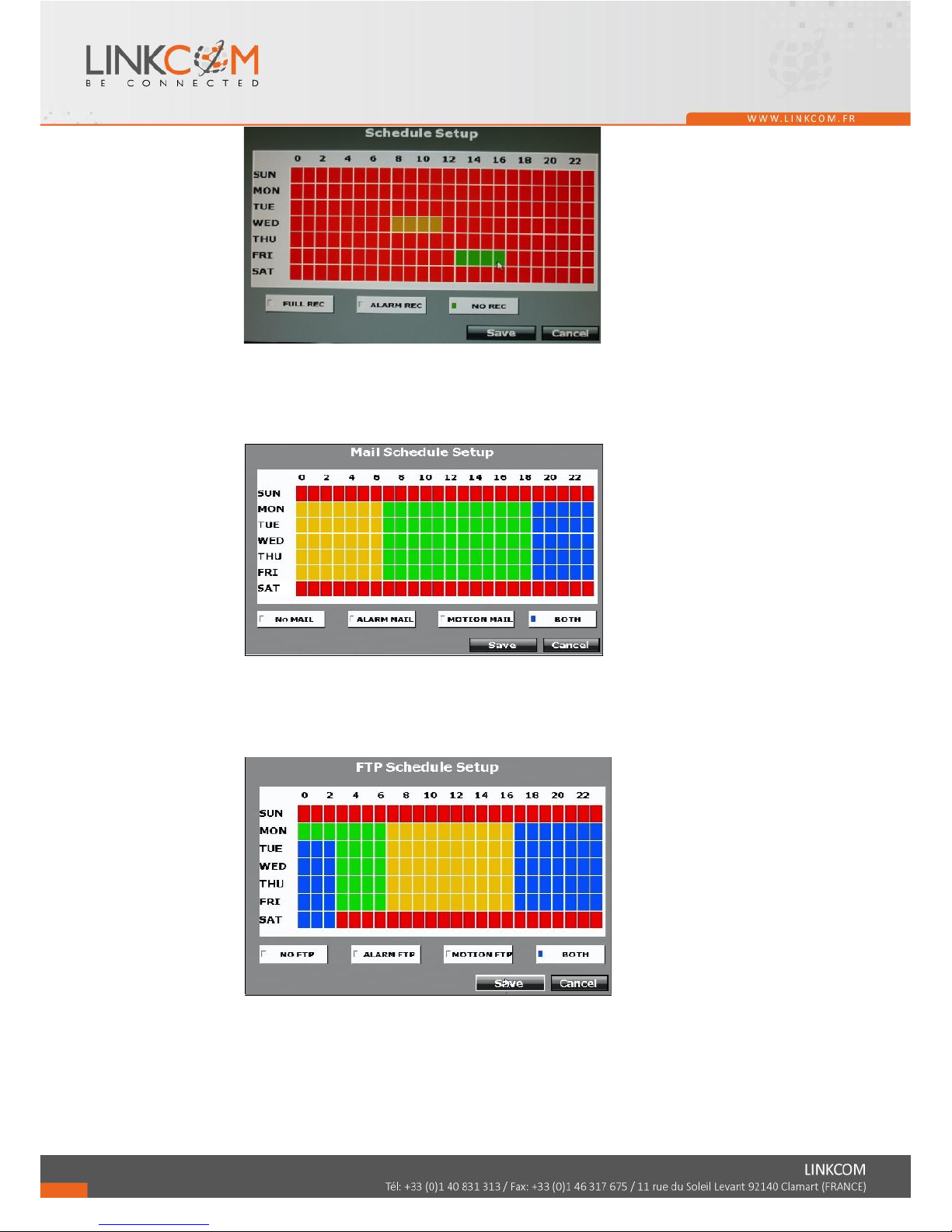
a. Schedule Setup:
Page 27
28
Click the tag “Full Recording”(Red) / “Alarm Recording”(Yellow) / “No
Recording”(Green), and then draw on the calendar. The recording type will follow
the schedule.
The tag “Alarm Recording” includes all alarm type.
b. Mail Schedule Setup:
Select the time that the recording video is sent to the mail address. No mail will be
sent during “NO MAIL” time period even the motion detection is triggered.
The tag “ALARM MAIL” refers to both external alarm and digital input(IPCAM).
c. FTP Schedule Setup:
Select the time that the recording video is upload to FTP. No file will be uploaded
during “NO FTP” time period even the motion detection is triggered.
The tag “ALARM FTP” refers to both external alarm and digital input(IPCAM).
3. Alarm Trigger: Start recording when any type of alarm event happen. The
recording video length is according to the setting of “Pre-Alarm Record Time”
and “Post-Alarm Record Time”.
Page 28
29
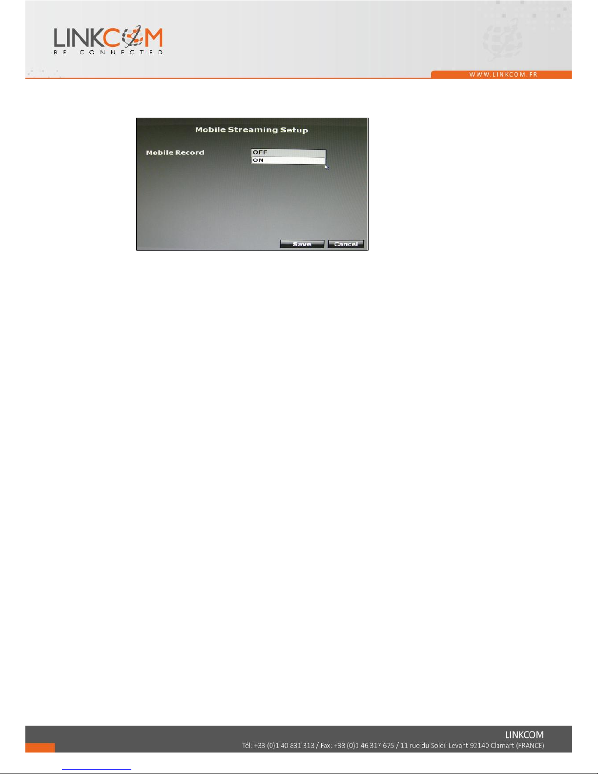
C. Mobile Streaming Setup
Select “ON” to record the streaming for mobile viewing.
Page 29
30
3.5 ALARM SETUP
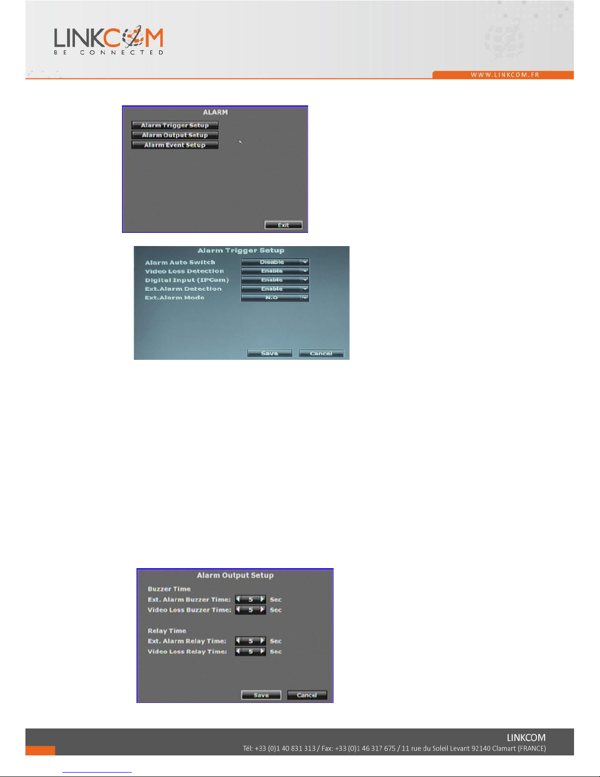
A. Alarm Trigger Setup
A-1. Alarm Auto Switch
Use the drop down list to switch the alarm auto switch. When the alarm is
triggered, the screen will switch to full screen, split screen (4CH split screen) or
disable.
A-2. Video Loss Detection
Use the drop down list to switch the video loss detection. When the video loss is
detected, the alarm will trigger.
A-3. Digital Input (IPCam)
Use the drop down list to switch on /off the Digital Input from IP camera. When
the DI signal is received from camera, the alarm will be triggered.
A-4. Ext. Alarm Detection
Use the drop down list to switch the external alarm detection. When the external
alarm is detected, the alarm will be triggered.
A-5. Ext. Alarm Mode
Use the drop down list to switch the external alarm mode. If the external alarm is
setup for normal open, the option has to switch to N.O.; in contrast, the option is
setup in N.C.
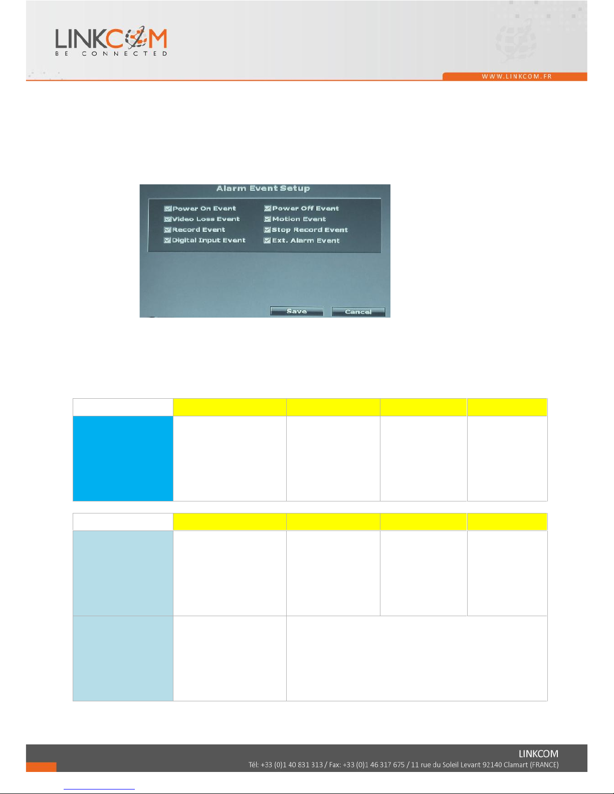
B. Alarm Output Setup
Page 30
31
This control item separates into two parts, “Buzzer Time” and “Relay Time”. User can
press ◄ or ► to switch the external buzzer time and video loss buzzer time in “Buzzer
Time” option. The adjustment value is from 5 to 99 seconds. Moreover, among “Relay
Time” option, the user can press ◄ or ► to switch the external buzzer time and video
loss buzzer time. The adjustment value is from 5 to 99 seconds as well.
The Value of Ext. Alarm Buzzer / Relay Time determine the buzzer / relay time of both
external alarm in and digital input (IPCam).
C. Alarm Event Setup
When the selected events are happened and triggered, the log will be recorded in the
event playback list, and you can use event search in playback to find them.
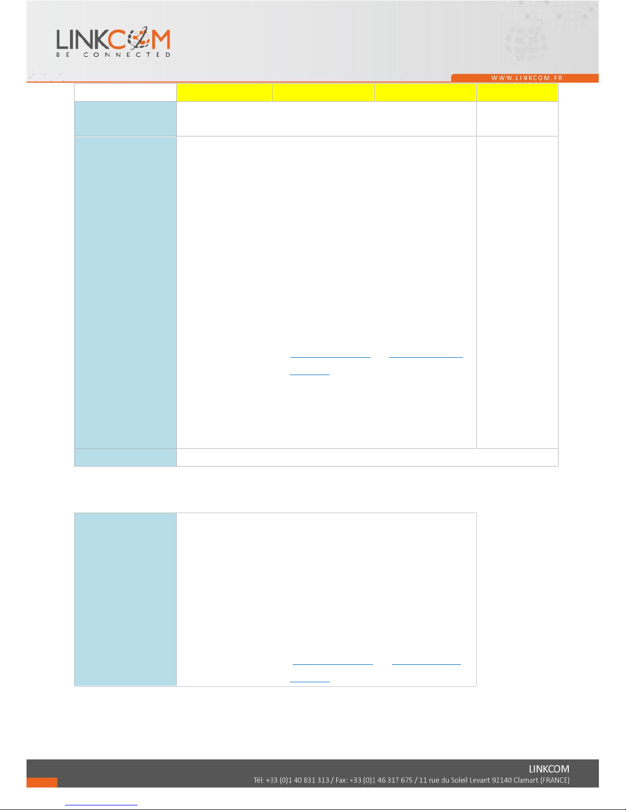
D. Alarm Action and Trigger Condition List
Action \ Type
Motion detection
External Alarm
DI (IPCAM)
Video Loss
Necessary Condition
(All the action below
can only be execute
when necessary
condition is met.)
Camera Setup >>Motion
Setup >>Tick "Area 1/2/3"
and set up the area
Alarm Setup >>Alarm
Trigger Setup >>"Ext.
Alarm Detection" set to
"Enable"
Alarm Setup
>>Alarm Trigger
Setup >>"Digital
Input (IPCam)" set to
"Enable"
Alarm Setup
>>Alarm Trigger
Setup >>"Video
Loss Detection" set
to "Enable"
Action \ Type
Motion detection
External Alarm
DI (IPCAM)
Video Loss
Switch to Single
Channel Screen / Split
Screen
Condition:
Alarm Setup >>Alarm
Trigger Setup >>"Alarm
Auto Switch" set to "Full
Screen(/Split Screen)"
XXX
Trigger Relay/ Buzzer
Condition:
Camera Setup >>Motion
Setup >>"Relay(/Buzzer)
Dwell" not set to "Off"
(It's enabled as long as Necessary Condition is meet)
*p: Trigger length setting: Alarm Setup >>Alarm Output Setup
>>Relay(/Buzzer) Time
*p:"Ext. Alarm Relay(/Buzzer) Time" length setting determines the
trigger lenth of both "External Alarm" and "DI(IPCAM)"
Page 31

32
Written in Log
(Can be used for event
search playback)
Condition:
Alarm Setup >>Alarm Event Setup >>Tick "Motion Even" / "Ext. Alarm Eventt" / "Digital Input
Event" / "Video Loss Event"
Icon on Live Screen
Page 32
33
Action \ Type
Motion detection
External Alarm
DI (IPCAM)
Video Loss
Pre- / Post-alarm
Recording
O
Pre-:O Post-:X
Send E-mail / Upload to
FTP with Pre-/
Post-alarm Recording
(*p[1])
Condition 1:
Network Setup >>Mail(/FTP) Setup >>Tick "Motion(/Alarm)"; And Record
Setup >>"Record Mode" set to "Manual"; And it's on recording when alarm
is triggered
Condition 2:
Network Setup >>Mail(/FTP) Setup >>Tick "Motion(/Alarm)"; And Record
Setup >>"Record Mode" set to "Alarm Trigger"
Condition 3:
Record Setup >>"Record Mode" set to "Schedule"; And Record Setup
>>Schedule Setup >>It's on "Full Rec" or "Alarm Rec" period when alarm is
triggered; And Record Setup >>Mail(/FTP) Schedule Setup >>It's on
"Motion/(Alarm) Mail(/FTP)" period when alarm is triggered
※It's enabled when both Necessary Condition and one of above three
conditions are met.
*p: Mail/FTP server setting: Network Setup>>Mail(/FTP) Setup>>Fill in
server information
*p: Pre-/ Post-alarm recording length setting: Record
Setup>>Pre(/Post)-Alarm Record Time
X
Http CGI
Network Setup>>HTTP Notification Setup>>Fill in Http server information and tick "Enable"
*p[1]: Or, in another interpretation way:
Send E-mail / Upload to
FTP with Pre-/
Post-alarm Recording
Condition 1:
Record Setup >>"Record Mode" set to "Manual" or "Alarm Trigger". It's not
on "Stop Rec" period; And Network Setup >>Mail(/FTP) Setup >>Tick
"Motion(/Alarm)"
Condition 2:
Record Setup >>"Record Mode" set to "Schedule". It's not on "No Rec"
period; And Mail(/FTP) Schedule Setup >> It's not on "No Mail(/FTP)"
period
※It's enabled when both Necessary Condition and one of above two
conditions are met.
Page 33
34
3.6 NETWORK SETUP
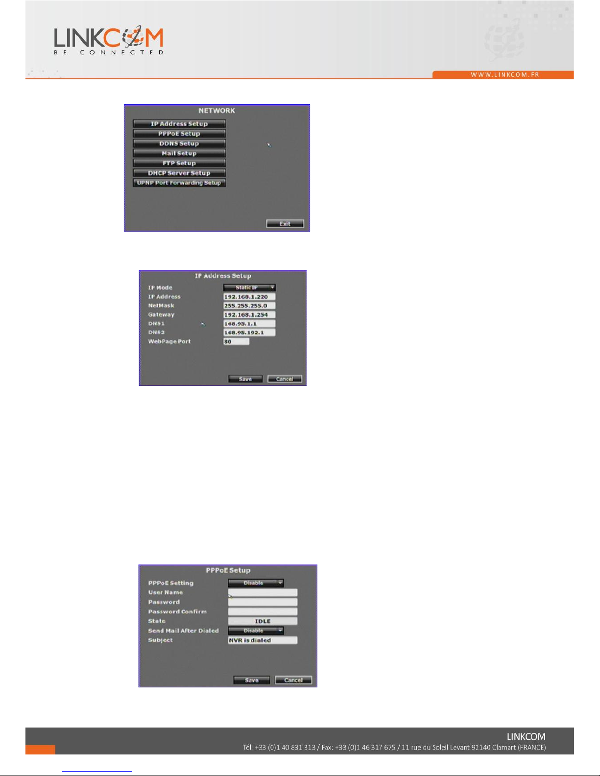
A. IP ADDRESS SETUP
Press ◄ or ► to setup NVR IP address.
A-1. IP Mode
Press drop down list to change IP mode to Static IP or DHCP.
A-2. IP Address
Give the NVR IP Address.
A-3. NetMask
Give the subnet mask which we usually set to 255.255.255.0.
A-4. Gateway
Give NVR gateway.
A-5. DNS1 & DNS2
Key in DNS1 and DNS2 that are provided by ISP.
A-6. WebPage Port
Give the NVR http port for web browser. Default is 80.
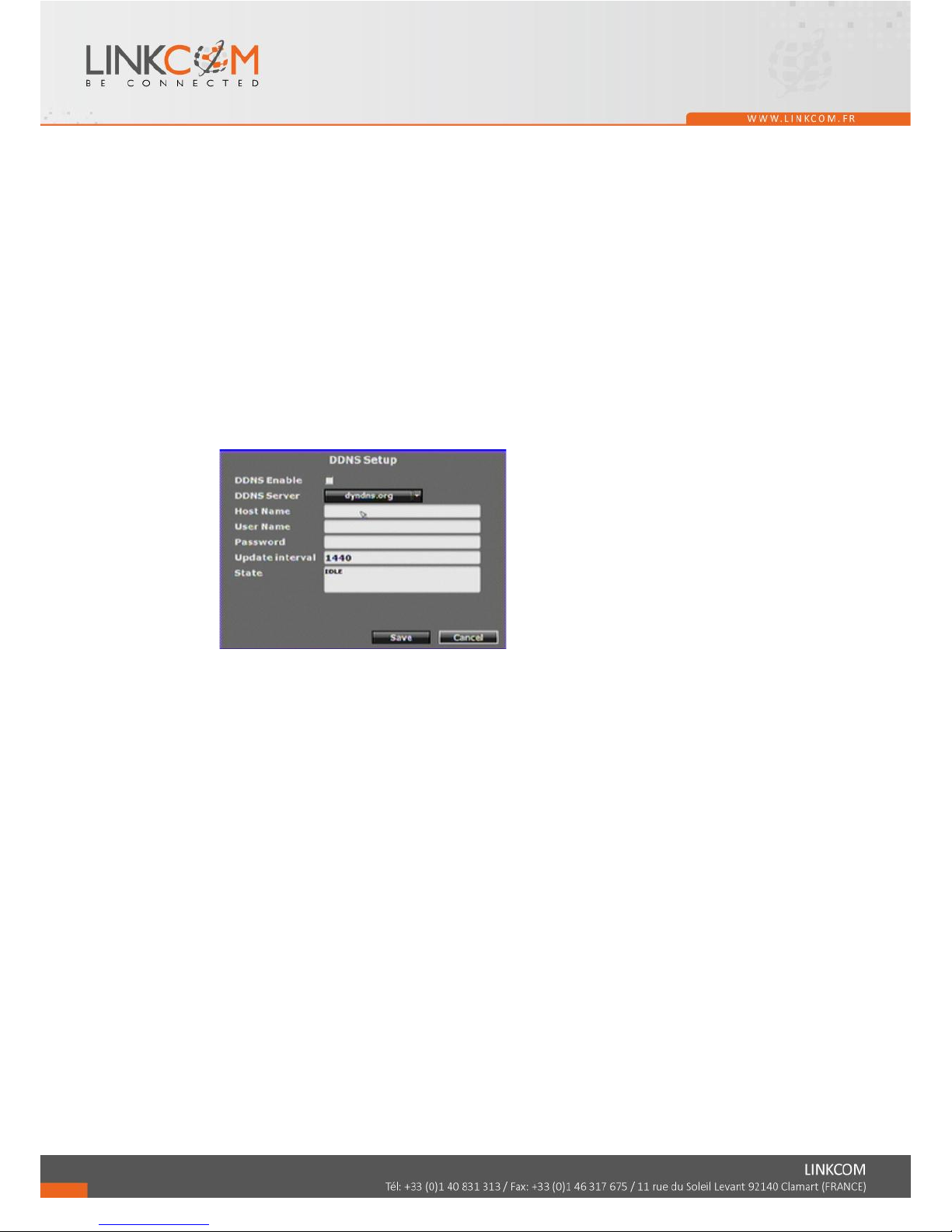
B. PPPoE SETUP
Page 34
35
B-1. PPPoE Setting
Press the drop down list to enable or disable PPPoE.
B-2. User Name
Insert the user name (ADSL account) which provided from local ISP.
B-3. Password
Insert the password which provided from local ISP.
B-4. Password Confirm
Insert the password again to confirm the password.
B-5. State
Present the current status of PPPoE function.
B-6. Send Mail After Dialed
Click the drop down list to enable or disable the function.
B-7. Subject
Insert the mail subject when dialed successfully.
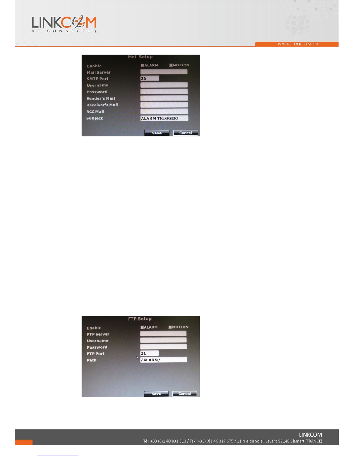
C. DDNS SETUP
C-1. DDNS Enable
Click the checkbox to enable or disable DDNS function.
C-2. Provider
Click the drop down list to select DDNS provider.
C-3. Host Name
Insert the registered host name in the selected provider.
C-4. User Name
Insert the registered user name in the selected provider.
C-5. Password
Insert the registered password in the selected provider.
C-6. Update Interval
A period of time to update IP address.
C-7. State
The state after apply for DDNS.
Updating: Information update.
Idle: Stop service.
DDNS registered successfully, now log by
http://<username>.ddns.camddns.com: Registered successfully.
Updating Failed, the name is already registered.
Updating Failed, please check your internet connection.
Page 35
36
D. MAIL SETUP
D-1. Enable
Tick “Alarm” to send video to the mail address when external alarm or DI from
IPCam is triggered. Tick “Motion” to send video to the mail address when
motion detection is triggered.
D-2. Mail Server
The IP address of Mail Server
D-3. SMTP Port
The port of SMTP (known as Simple Mail Transfer Protocol). (Default value is
25)
D-4. User Name
The user name while log in to the mail server.
D-5. Password
The password while log in to the mail server.
D-6. Sender’s Mail
The sender’s account when send the mail via this mail server.
D-7. Receiver’s Mail
The receiver’s mail address.
D-8. BCC Mail
The receiver’s mail address for Bcc Mail.
D-9. Subject
The subject while sending the mail.
E. FTP SETUP
E-1. Enable
Tick “Alarm” to upload video to FTP when external alarm or DI from IPCam is
triggered. Tick “Motion” to upload video to FTP when motion detection is
Page 36
37
triggered
E-2. FTP Server
The IP address of FTP Server.
E-3. User Name
The username while log in to the ftp server.
E-4. Password
The password while log in to the ftp server.
E-5. FTP Port
The port number of file transmission. (Default value is 21)
E-6. Path
The ftp path where the user wants to reserve the information.
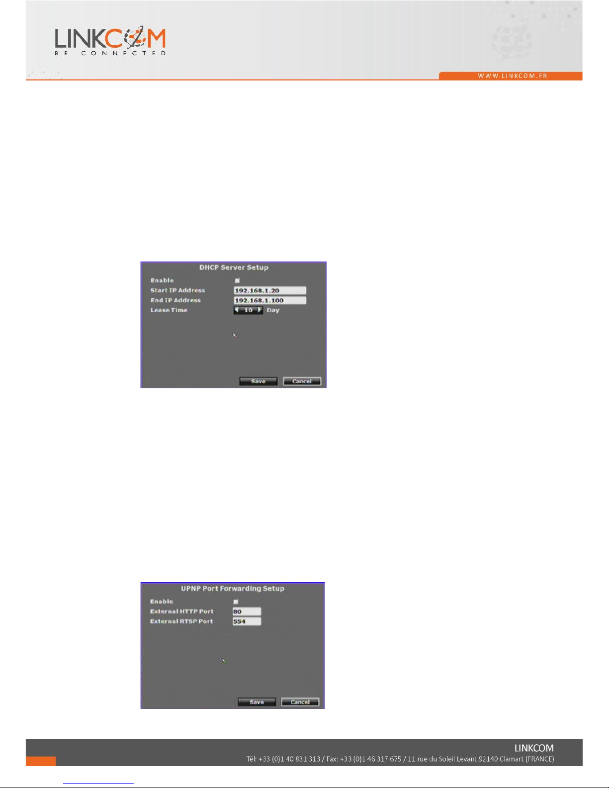
F. DHCP Server Setup
F-1. Enable
Use the checkbox to enable or disable DHCP Server function. When the function
is activated, the NVR can be treated as the DHCP server. The NVR will assign or
distribute one of the IP address which is according to the setup IP address range
(start and end IP Address.) to the connecting IPCAM (setup DHCP function as
well).
To use DHCP server function, the IP address of NVR itself has to be static IP.
F-2. Start IP Address
Use the virtual keypad to insert the start IP Address of DHCP server.
F-3. End IP Address
Use the virtual keypad to insert the end IP Address of DHCP server.
F-4. Lease Time
Press ◄ or ► to change the lease time of DHCP server.
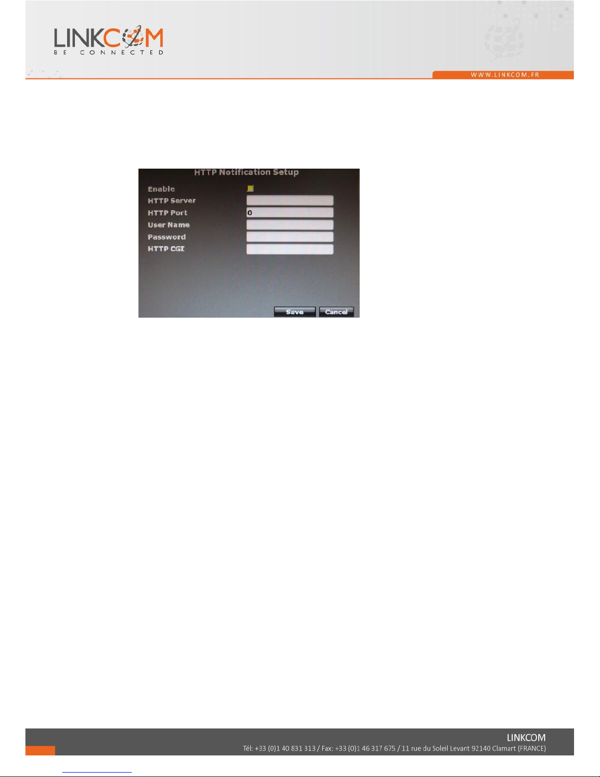
G. UPNP Port Forwarding Setup
G-1. Enable
Page 37
38
Use the checkbox to enable or disable UPNP port setup.
G-2. External HTTP Port
Use the virtual keypad to insert the external http port.
G-3. External RTSP Port
Use the virtual keypad to insert the external rtsp port.
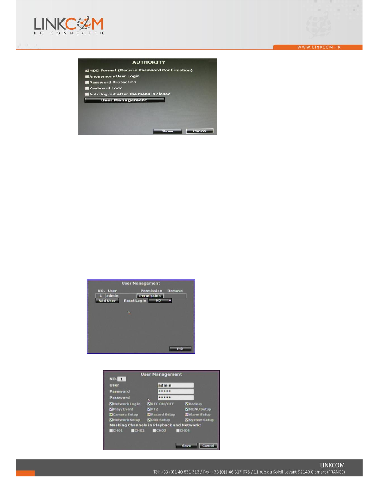
H. HTTP Notification Setup
H-1. Enable
Use the checkbox to enable or disable HTTP Notification. This function allows users
to set up the CGI command to a HTTP server. The server can be any device that can
receive CGI via HTTP protocol. When alarm events happen, NVR sends CGI to that
server.
H-2. HTTP Server
Key in the server IP address.
H-3 HTTP Port
Key in the server port used for http protocol.
H-4 User Name
Key in the server username.
H-5 Password
Key in the server password.
H-6 HTTP CGI
Key in the CGI that you would like to send to the server when alarm events happen.
Page 38
39
3.7 AUTHORITY SETUP
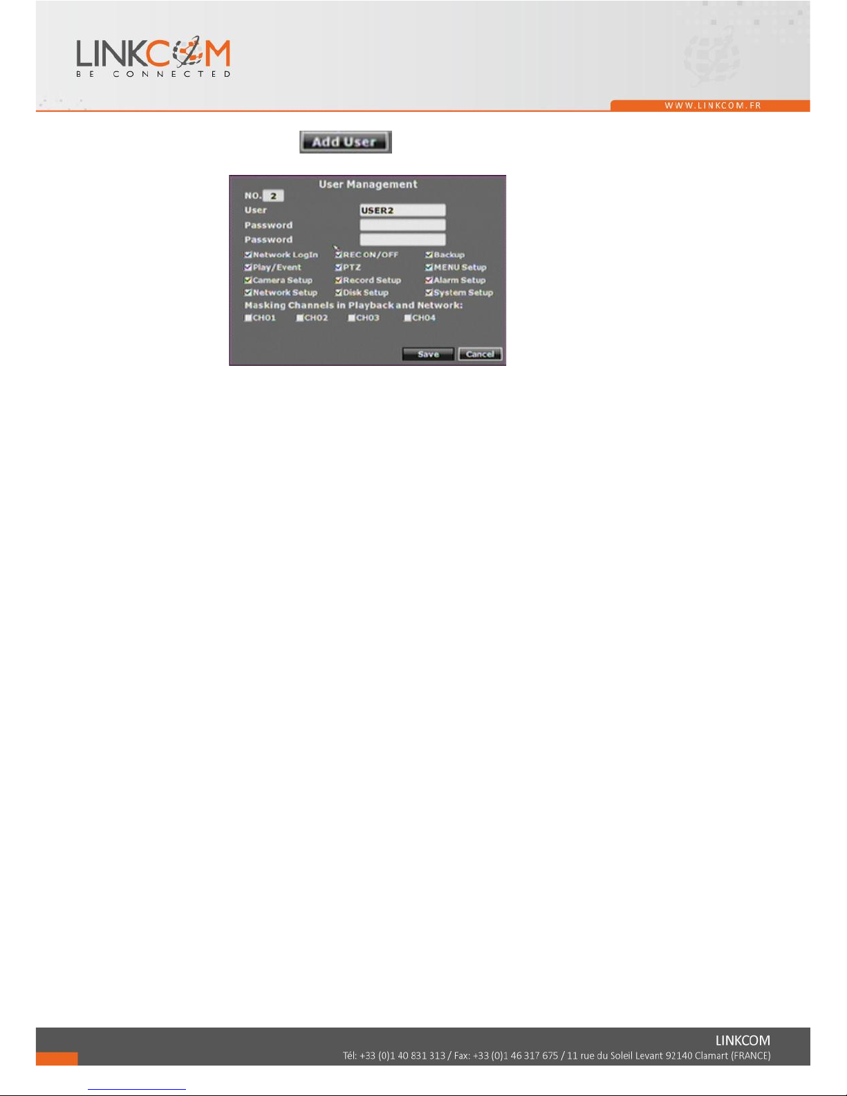
A. HDD Format
Use the checkbox to enable or disable the authority of HDD Format function. If
enable this function, the user has to insert password while performing HDD format.
B. Anonymous User Login
Use the checkbox to enable or disable the authority of anonymous user login. If enable
this function, the user does not have to insert the username/ password and can view
the live image via IE browser.
C. Password Protection
Use the checkbox to enable or disable the authority of password protection.
D. Keyboard Lock
Use the checkbox to enable or disable the operation of control bar which is in the right
hand side of live view. The control bar can not work when keyboard lock is activated.
E. Auto Logout
Use the checkbox to enable or disable the operation. If enabled, the system will log
out automatically after the menu closed.
F. User Management
Among this item, user can setup the user management permission and the user
authority management.
F-1. Permission
Use the mouse to click the checkbox to modify and alter the user authority.
Page 39
40
F-2. Add User
After click button, the setup page will present in the following.
The user can distribute the authority and the permission for the new user.
Page 40
41
3.8 DISK MANAGEMENT
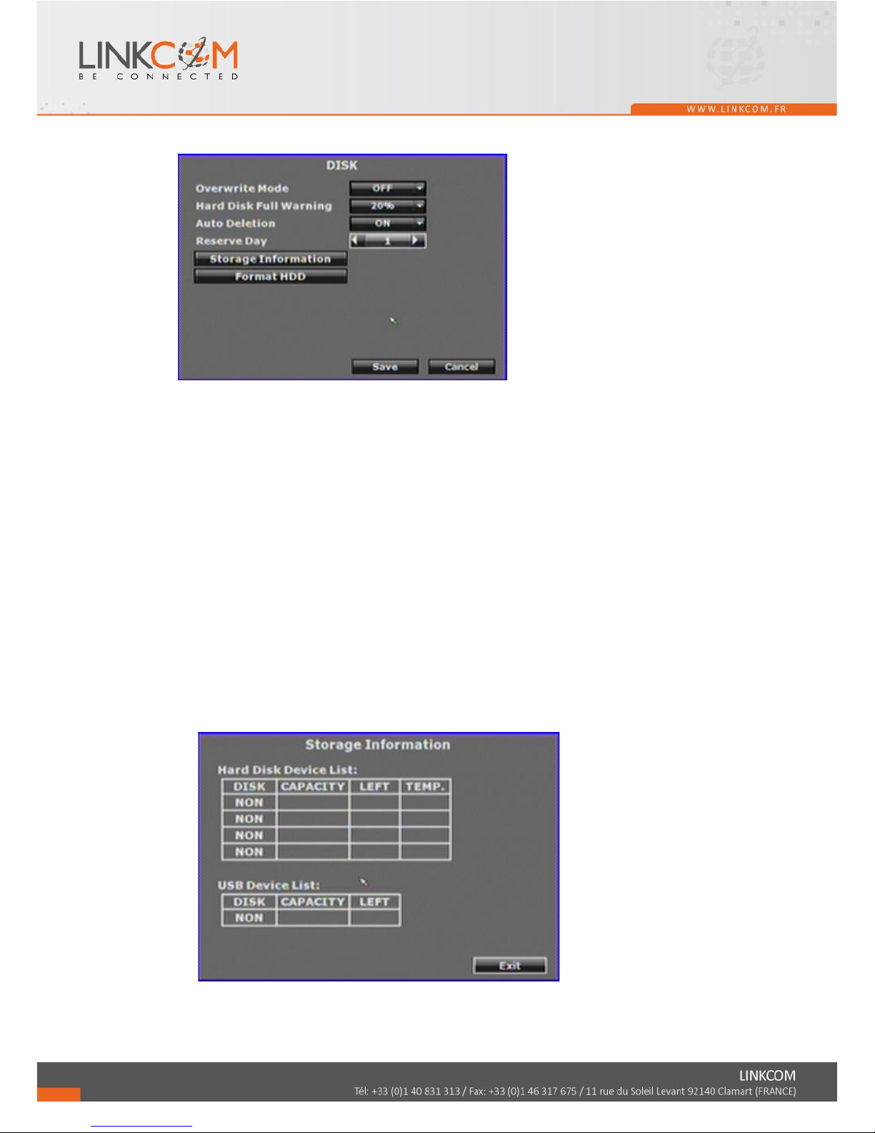
A. Overwrite Mode
Select “ON”, then the oldest recording data will be overwritten by new recording data.
Select “OFF”, then NVR will stop writing recording data into HDD when the HDD is
full.
B. Hard Disk Full Warning
Under non-overwrite mode, click the drop down list to change value to 20%/ 15%/
10% or 5% . When the HDD space is less then setting ratio, the buzzer buzzes.
C. Auto Deletion
Select “ON”, then on the playback list, users cannot find the recording data that is
older than the reserve day.
For example, it’s 2012/10/19 17:40 now. Auto deletion is set as on, and reserve day is
set as 3. The recording data which recording time is order than 2012/10/16 17:40 will
not be indicated on the playback menu.
D. Reserve Day
Use ◄ or ► to setup the reserve day between 1~30 days.
Note: If the “Overwrite Mode” is set OFF and NVR keeps recording, the HDD will
finally get full regardless that “Auto Deletion” is ON.
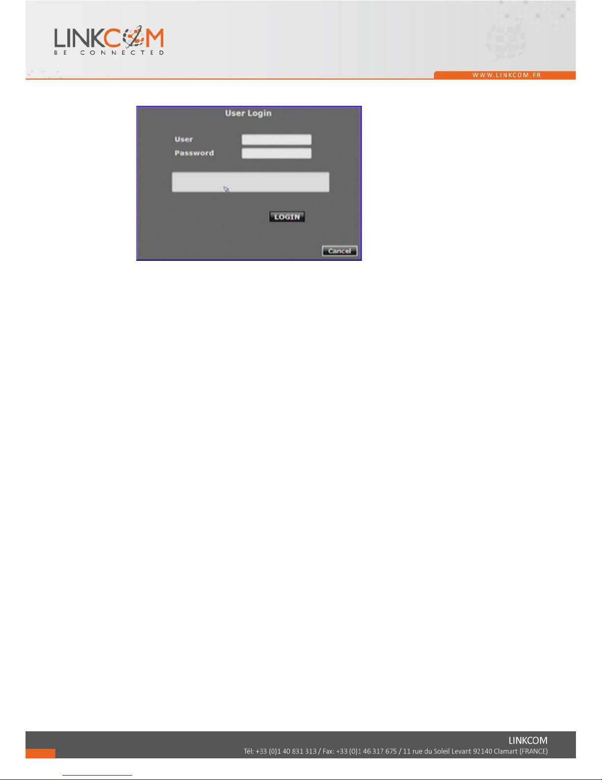
E. Storage Information
The information of storage device will present in this page.
Page 41
42
F. Format HDD
Insert the user name and password while performing HDD format function.
Page 42
43
3.9 SYSTEM SETUP
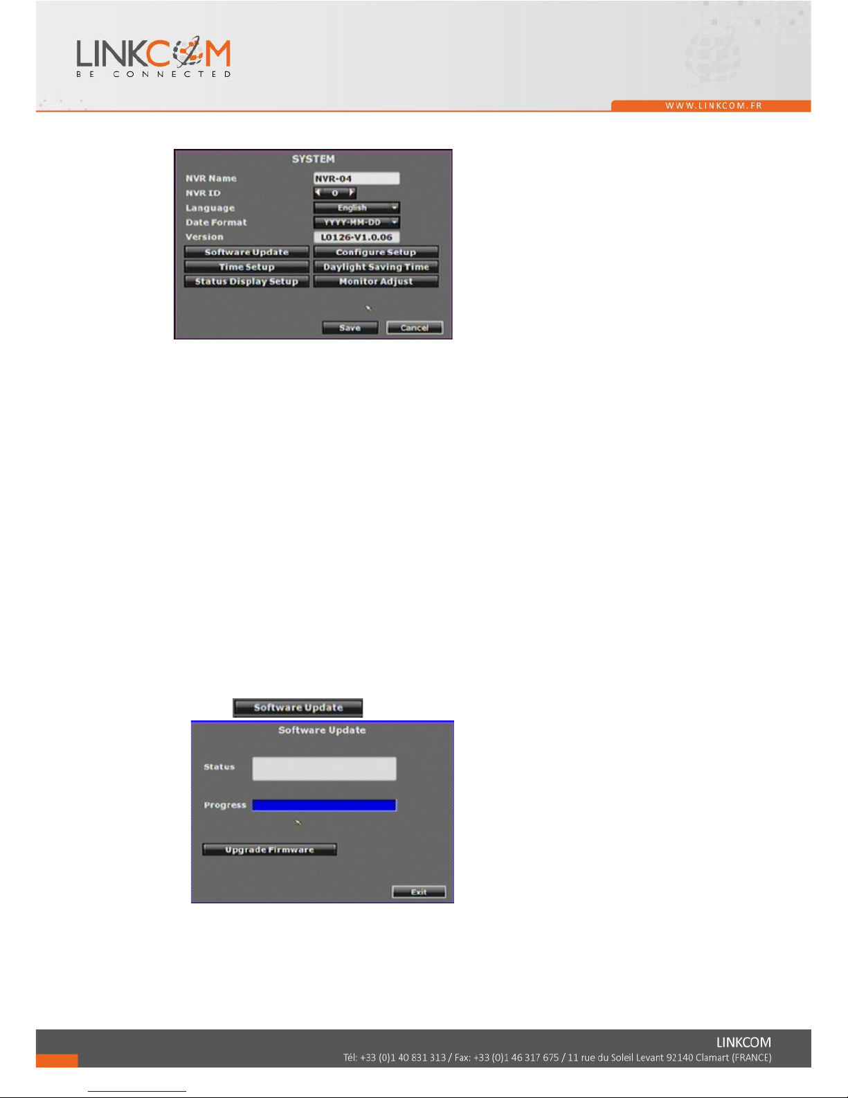
A. NVR Name
Use the virtual keypad to insert the name of the NVR.
B. NVR ID
Use ◄ or ► to setup the NVR ID. When you have several NVR, use ID to distinguish
them when you operate remote controller or other devise.
C. Language
Use the drop down list to change the NVR language. Currently, there are English,
Traditional Chinese and Simplified Chinese three options.
D. Date Format
Use the drop down list to change DATE. There are DD/MM/YYYY, YYYY/MM/DD
and MM/DD/YYYY three modes.
E. Version
The firmware version of the NVR will show in this column.
F. Software Update
Click button to perform firmware updating.
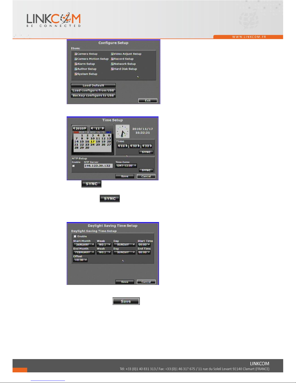
G. Configure Setup
Click the checkbox to select which item can be setup by the user. The user can also
load the setting to factory default, load the configure from USB and backup configure
to USB.
Page 43
44
H.Time Setup
Click button within “Time” block can adjust and synchronize the time of
the NVR as the system time of the PC. Moreover, if the user clicks the enable
checkbox and button within the NTP Setup block, the time of the NVR will
synchronize as the NTP Server.
I. Day Light Saving Time
After enable the daylight saving time function, the user can use the drop down list to
select the start time and the end time of daylight saving time. After complete the
setting, please click button to reserve the setting.
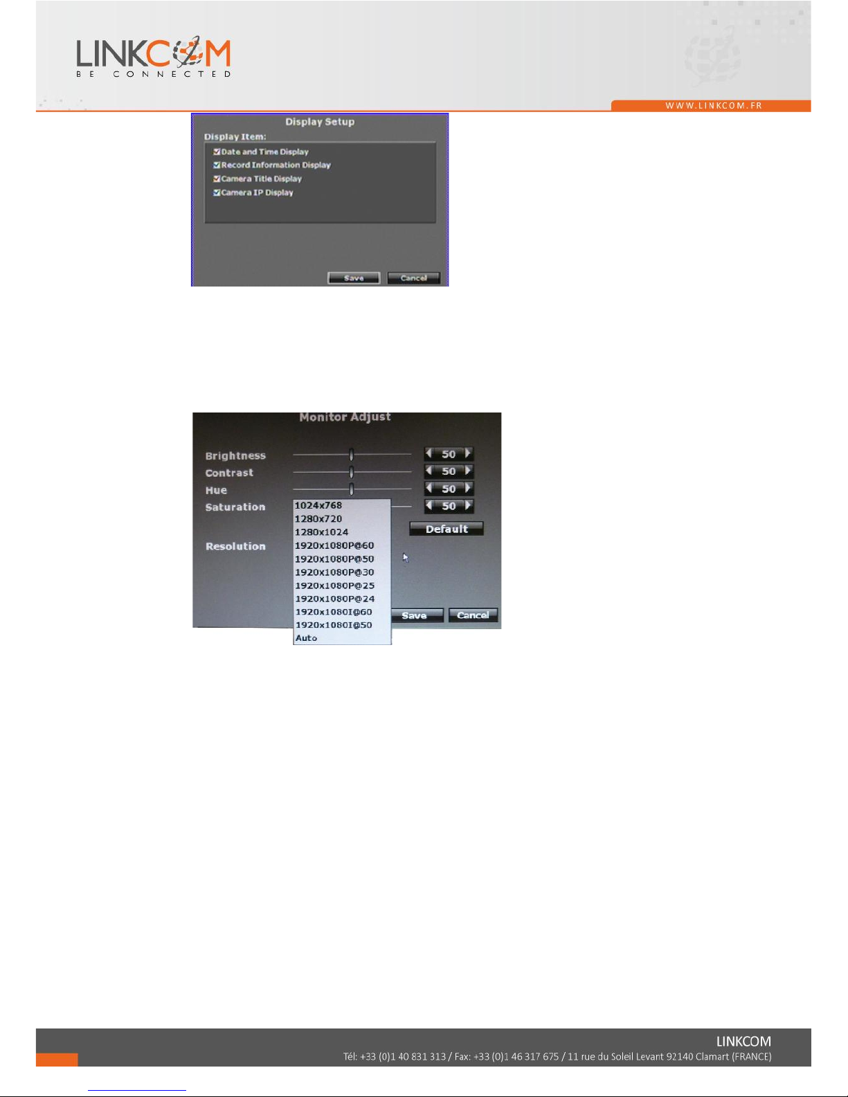
J. Status Display Setup
Use the mouse to click the options, which is including “Date and Time Display”,
“Record Information Display” and “Camera Title Display”.
Page 44
45
K. Monitor Adjust
User can use ◄ or ► to adjust the monitor related setting within this page, there are
“Brightness”, “Contrast”, “Hue” and “Saturation” four options can be set.
You can also adjust Resolution here. Please check the frame rate that your LCD
monitor support before you select. If you select a resolution not compatible with the
LCD monitor, the system will undo this recent change automatically.
Page 45
46
3.EX DEBUG MESSAGE
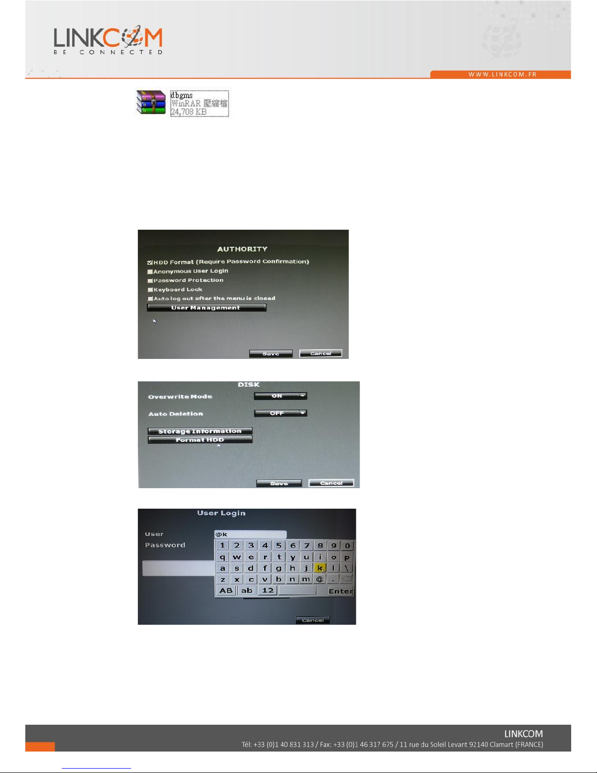
The purpose of the following procedure is to export a HDD debug message file. If user has
problems with the NVR, the technical person can analysis the file and might find the cause
of problem.
Plug in a USB disk.
Enter the Authority Setup page and make sure the option “HDD Format (Require
Password Confirmation)” is ticked.
Enter the Disk Setup page. Click “Format HDD”.
Key in “@k” in the user name column to login. No password is required.
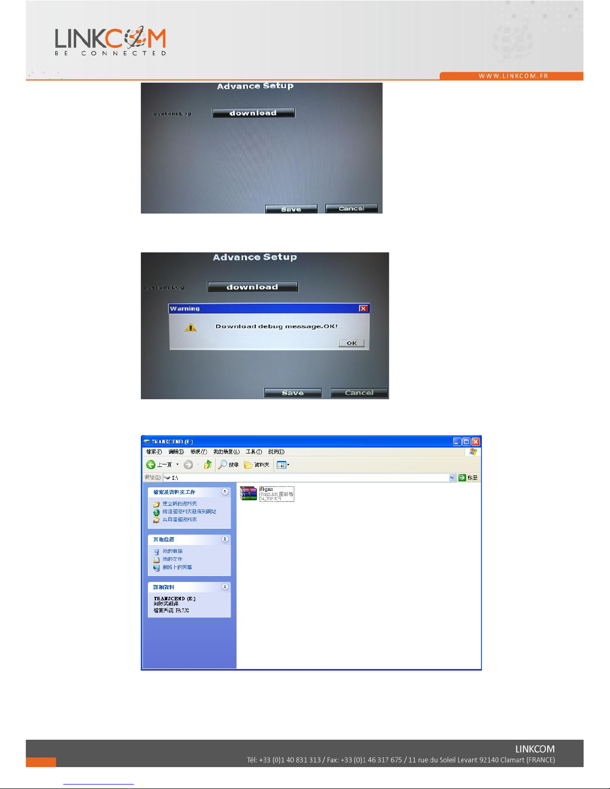
The screen turns to Advance Setup page. Click download. It takes about 10 seconds to
export the file.
Page 46
47
When the downloading is complete, a message pops up to remind the user. Click”
OK”.
Now the debug message file should have been in your USB disk. Please turn the file”
dbgms.tar” to Linkcom’s technical person.
Page 47
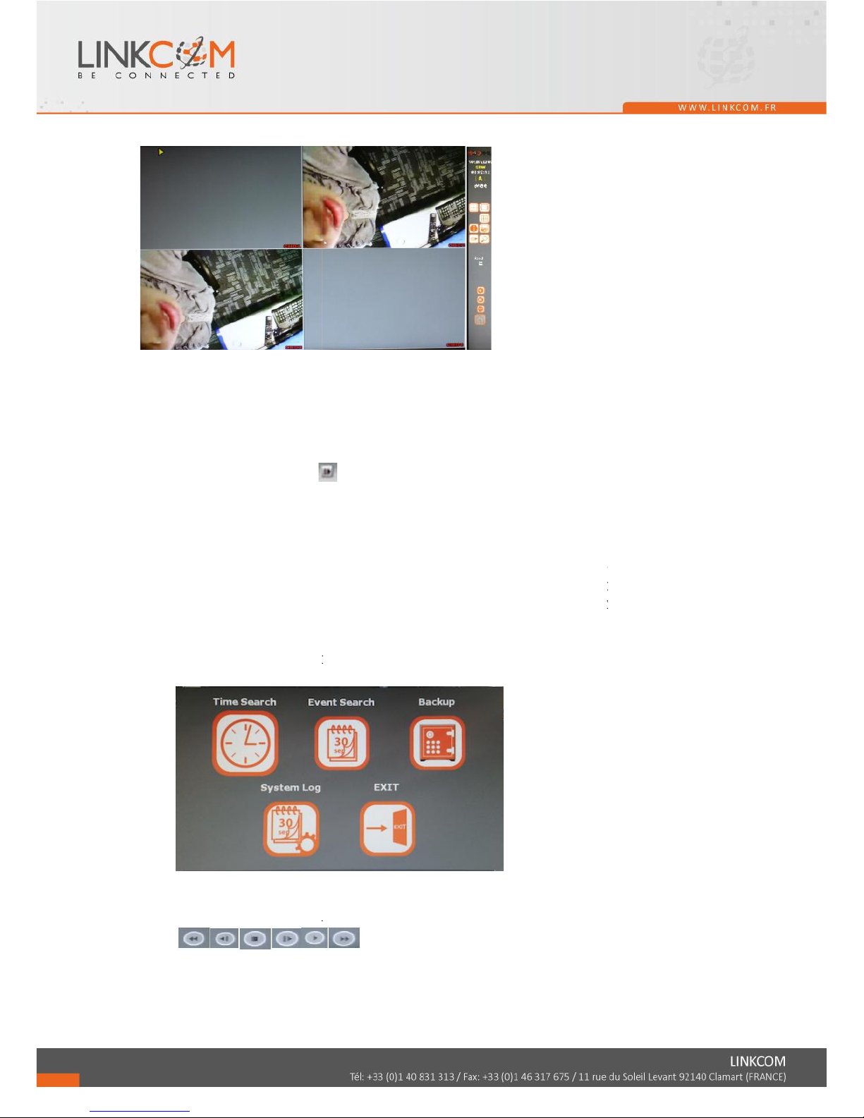
4 NVR PLAYBACK
Note: Under playback mode, it will output sound when switch to full screen mode.
A. RECORD BACKUP
With playback mode, press this button to backup record (.264 video backup) and press
this button again to finish backup. For performing the single image backup (.Y42 single
image backup), press first and then click this button to backup the necessary image.
B. DISPLAY CONTROL
Within playback mode, use display control to switch the camera channel.
C. DIGITAL ZOOM
In the live full screen mode, left-click the button of the mouse to pull a range to zoom in
or zoom out the image. User can right-click the button of the mouse to disable this
function. (NOTE: Using the mouse to operate digital zoom can zoom in to max. 16 times.)
Moreover, user can also use ZOOM key on the front panel to perform this function. (First,
click ZOOM Key and then click ▲▼◄► key to select zoom in or zoom out position.
Finally, click ENTER key to complete the setting. Moreover, click ZOOM Key again can
disable digital zoom function. Using the panel key to perform zoom in function is fixed at
2 times.)
D. FULL SCREEN
Press the bottom for full-screen mode.
E. RECORD AND PLAYBACK CONTROL
Same as front panel controller and remote controller.
48
Page 48
49
4.1 TIME SEARCH
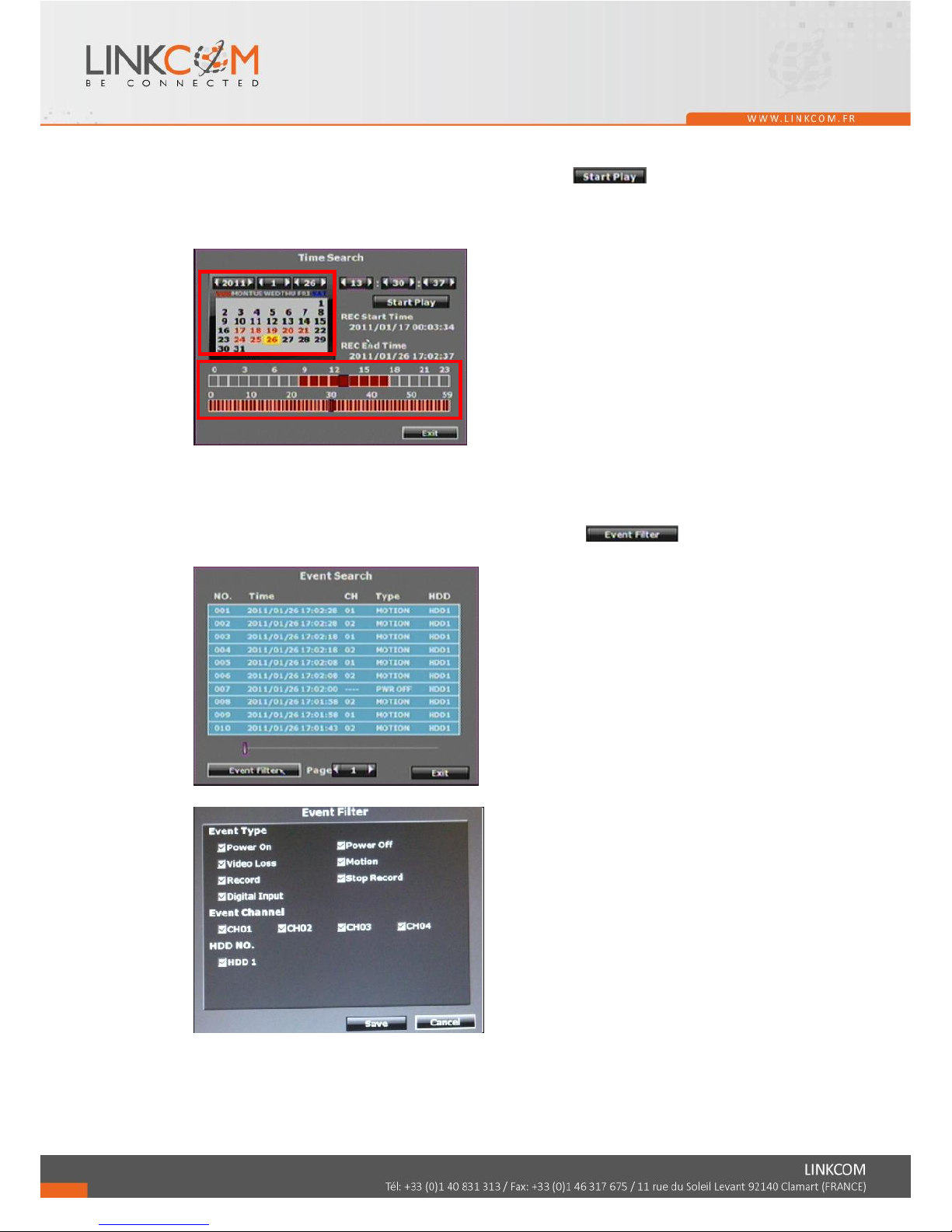
Select the start of playback time and then click button to playback the
recorded data. If the time contains the recorded data, the time point within this page will
become red.
4.2 EVENT SEARCH
After entry to the event search page, user can click the event log item which shown on the
list to start playback. Moreover, the user could click button to select the
specific event option to filter the event option that shown on the list.
Page 49
50
4.3 BACKUP
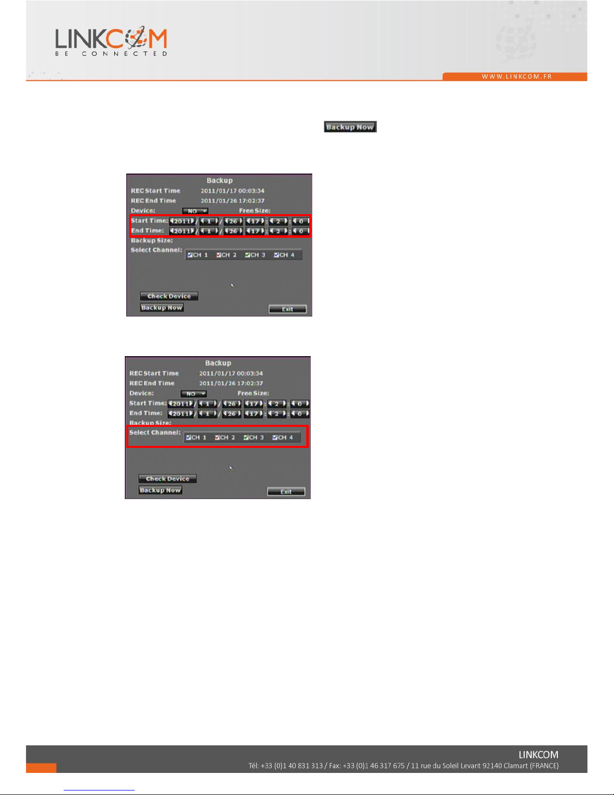
After click the backup button, the user could use drop down list to select the storage
device, USB/ DVD-RW (08CH/ 16CH models) and the backup time selection mode,
Time Mode/ Hours Mode. After that, click button to start backup.
TIME MODE
Click ◄ or ► to select the start and end backup time.
Moreover, among “Select Channel” option, use the mouse to select the channel which is
going to backup.
Page 50
51
4.4 SYSTEM LOG
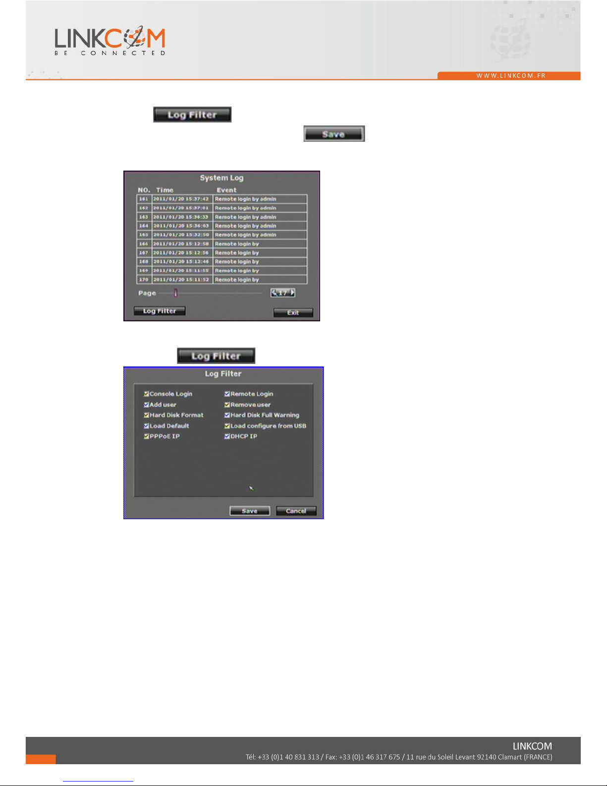
System log is reserved all of the system record. The maximum storage quantity is 2000.
Click button to perform the further data filter action. After complete
the specific item selection, please click button to reserve the setting. While
return to the system log page, it will only reveal the specific selection items.
After click button
Page 51
52
5 BACKUP PLAYBACK
SYSTEM REQUIREMENT
CPU: Intel Celeron 1.6G
MEMORY: 256MB.
VGA: 32MB
VGA RESOLUTION: 1024 x 768.
OS: Windows XP / 2000 or above
SUGGESTED REQUIREMENT
CPU: Intel P4 2.8G
MEMORY:512MB or above
VGA:64MB or above
VGA RESOLUTION:1024 x 768
OS: Windows XP / 2000 or above
NETWORK BANDWIDTH: Upload Speed is 256kbps or above
5.1 MAIN SCREEN SETTING
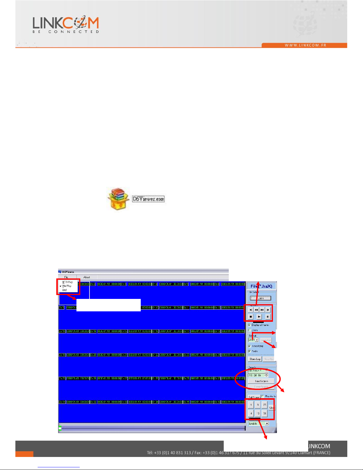
The player (D6Viewer.exe) is used to play the NVR backup
video. D6Viewer.exe can be obtained via the Internet; moreover, while performing
USB backup and DVD-RW backup, the software will be built automatically as well.
A. MAIN SCREEN
Open the D6Viewer. Use Overlay mode can improve the system resource
performance.
Select video source
Playback Control
Save as AVI
Time & Event
Search
Channels Divide Screen
Channel Selected
Page 52
53
B. HDD PLAY
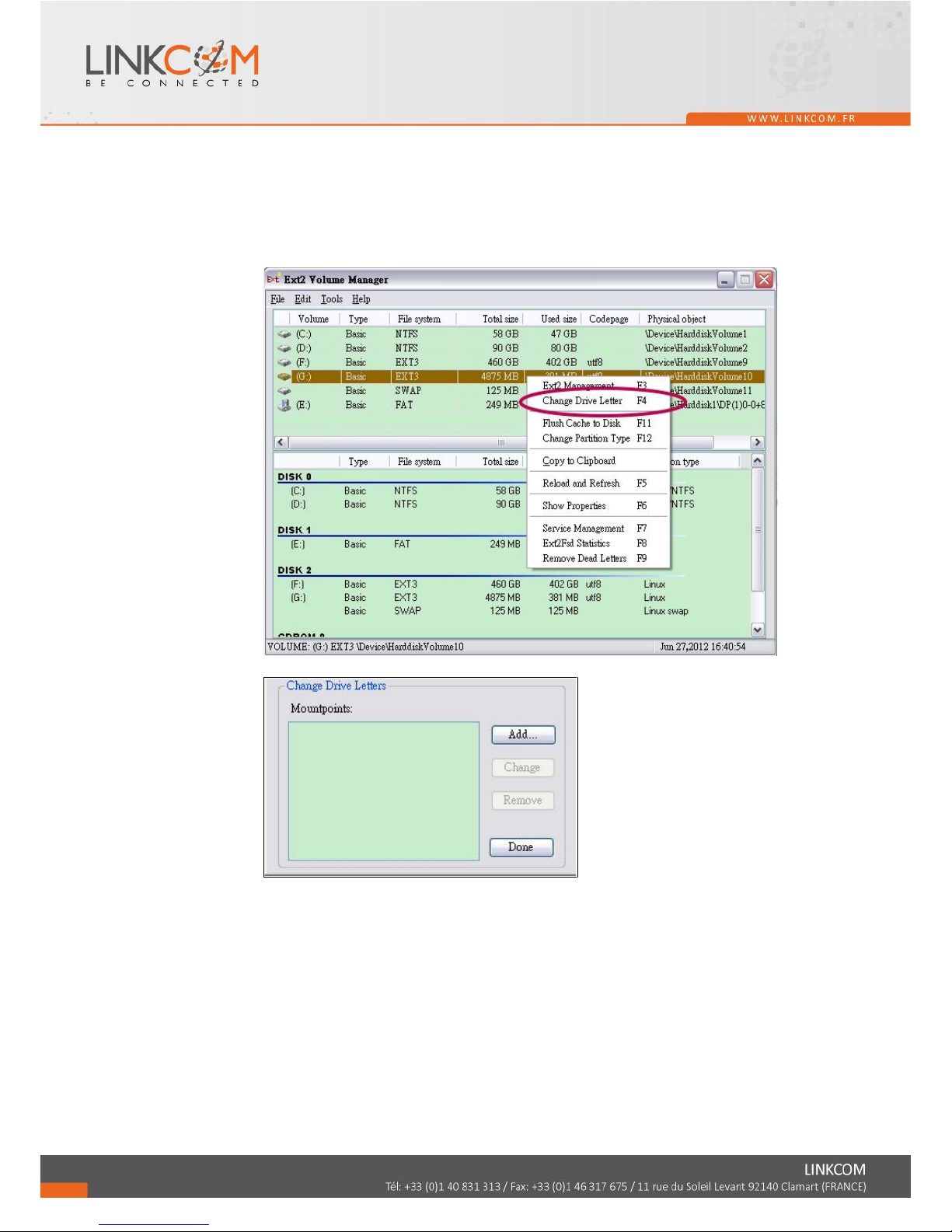
1. Remove the NVR HDD and connect it to the PC. The NVR HDD is Linux format,
so the Windows system may not know it. Please use the software “Ext2Fsd” to assign
a drive letter to the HDD. “Ext2Fsd” is in the attached CD or can be downloaded from
the Internet.
Start the Ext2Fsd, and it will detects all the disks connected with your PC.
Right-click on the NVR HDD and choose “Change Drive Letter”.
Click “Add”
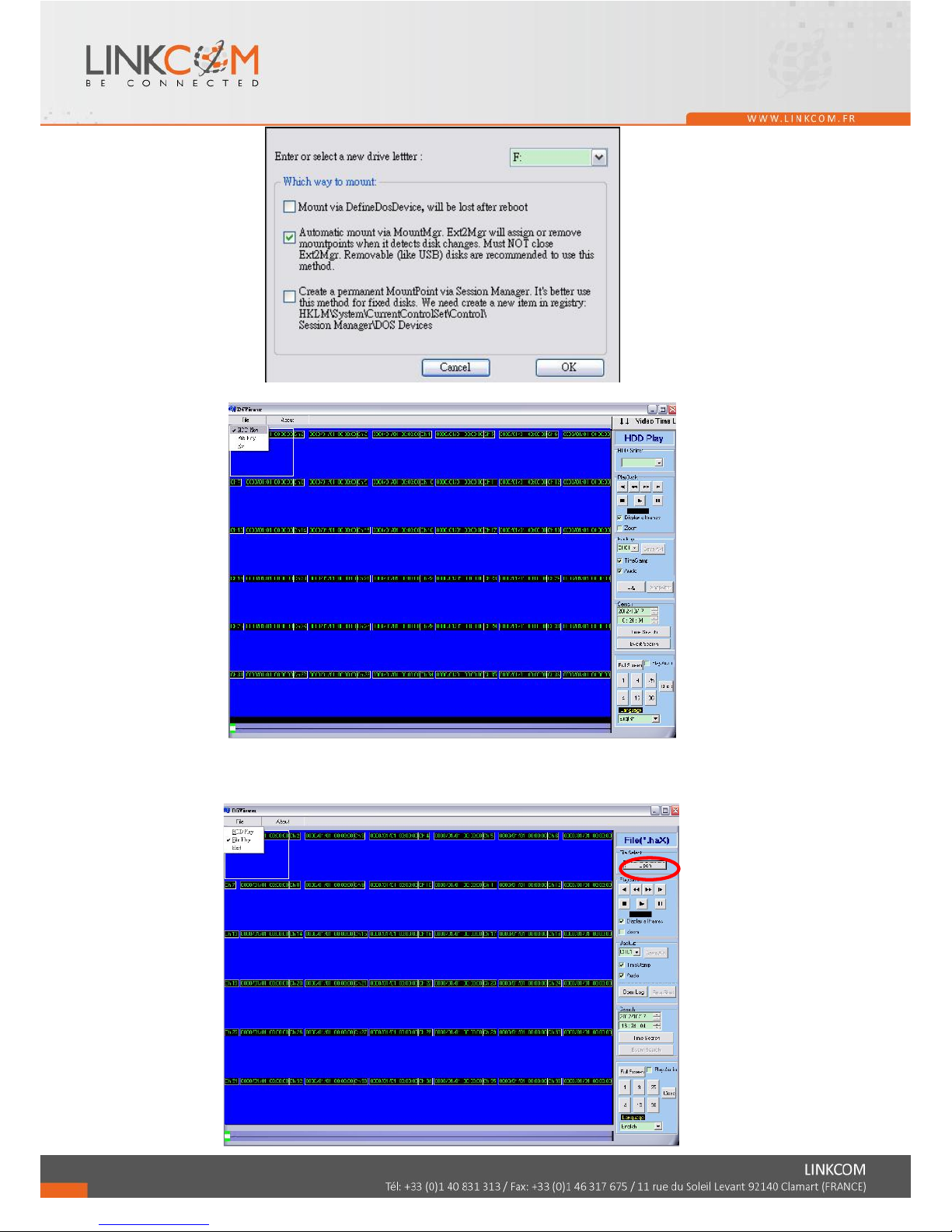
Assign a letter to the HDD, then click OK so that the HDD get the letter and can
be recognized by the Windows.
Page 53
54
2. Under HDD play mode, select the NVR HDD to load the video file in the HDD.
C. File Play
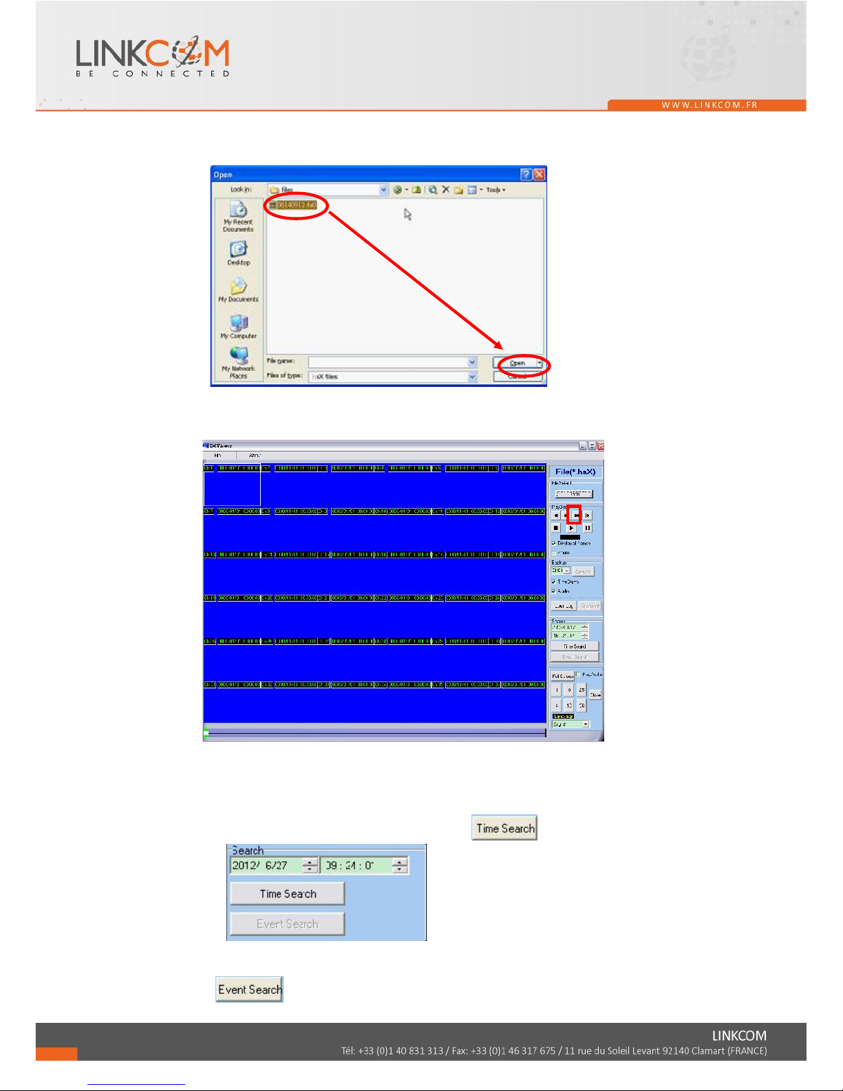
1. You can use D6Viewer to open a single video backup file. Under file play mode,
select "Open".
Page 54
55
2. Choose the path that the .haX file is reserved and pick the file to playback.
3. Press the play icon to play the video or still picture.
5.2 PLAYBACK OPERATION
A. TIME SEARCH
Select the Date and Time and then click to play the film.
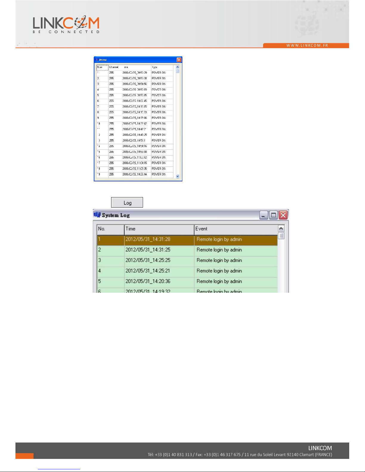
B. EVENT SEARCH
It will display all the events which are reserved within the NVR HDD after press
(Shown in the following) and double click left button of mouse to
Page 55
56
trigger event.
C. LOG
Click to check the log records.
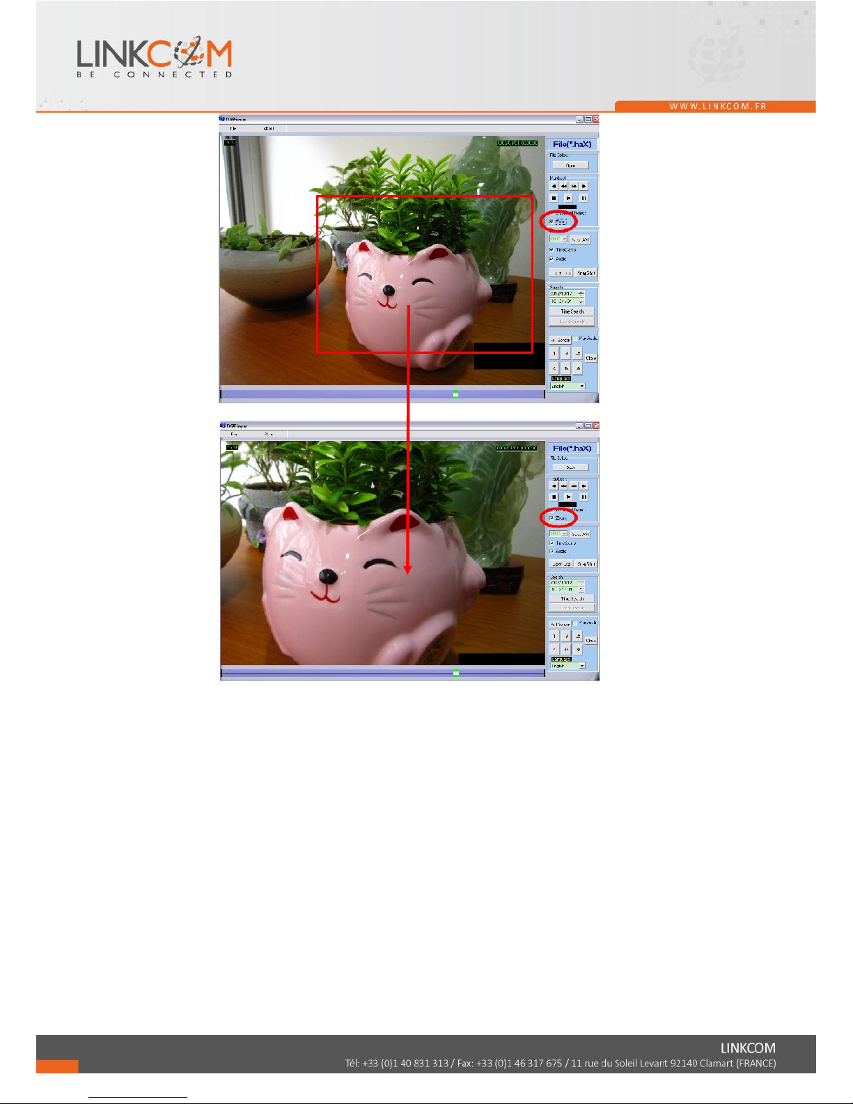
D. ZOOM
Tick the “Zoom” box and drag an area on the screen. Click the area to zoom in.
Page 56
57
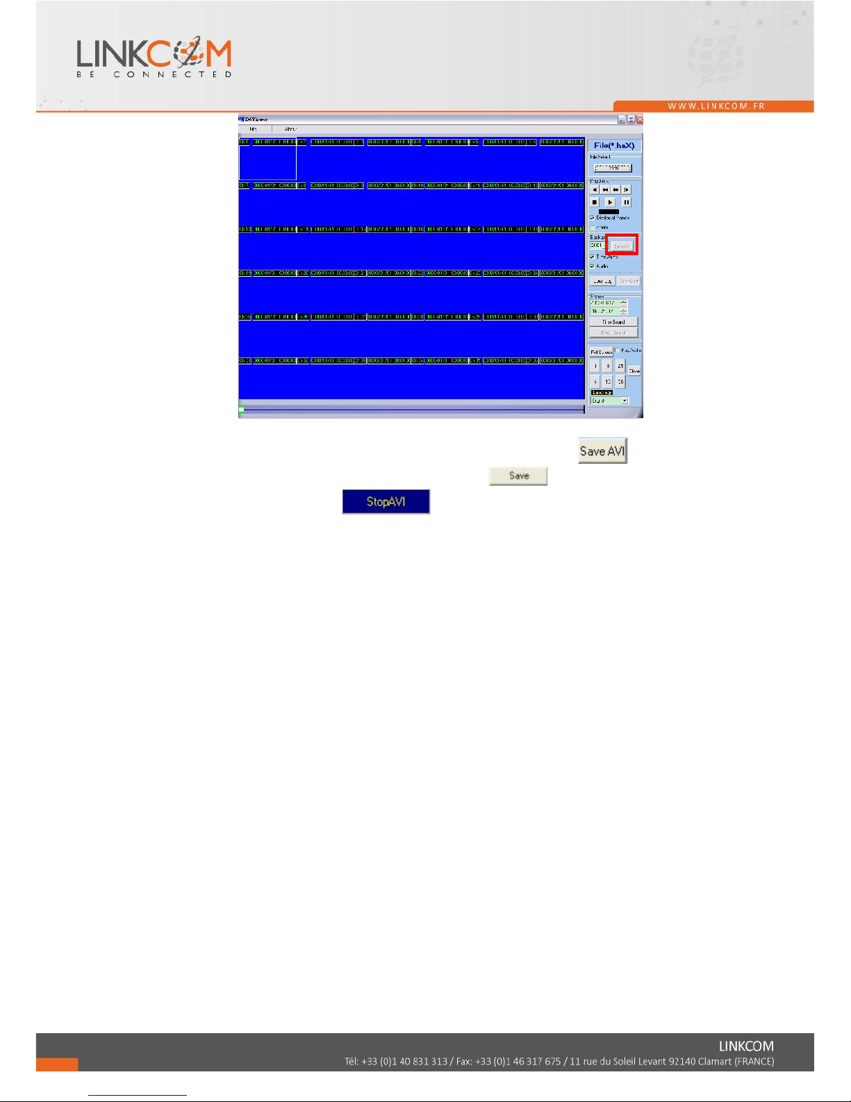
E. BACKUP FILE TO AVI
1. Please select specific channel to backup.
Page 57
58
2. During video playback mode please press AVI bottom to start.
3. Make up a filename and path than press bottom to start AVI backup.
4. Press AVI bottom to finish backup.
Page 58
59
6 NETWORK VIEWING & PLAYBACK
SYSTEM REQUIREMENT
CPU: Intel Celeron 1.6G
MEMORY: 256MB
VGA: 32MB
VGA RESOLUTION: 1024 x 768.
OS: Windows XP / 2000 or above
SUGGESTED REQUIREMENT
CPU: Intel P4 2.8G
MEMORY: 512MB or above
VGA: 64MB or above
VGA RESOLUTION: 1024 x 768
OS: Windows XP / 2000 or above
NETWORK BANDWIDTH: Upload Speed is 256kbps or above
6.1 IP ADDRESS SETUP ON PC SITE
Install cameras inside in LAN or use network cable to connect with PC. This is for
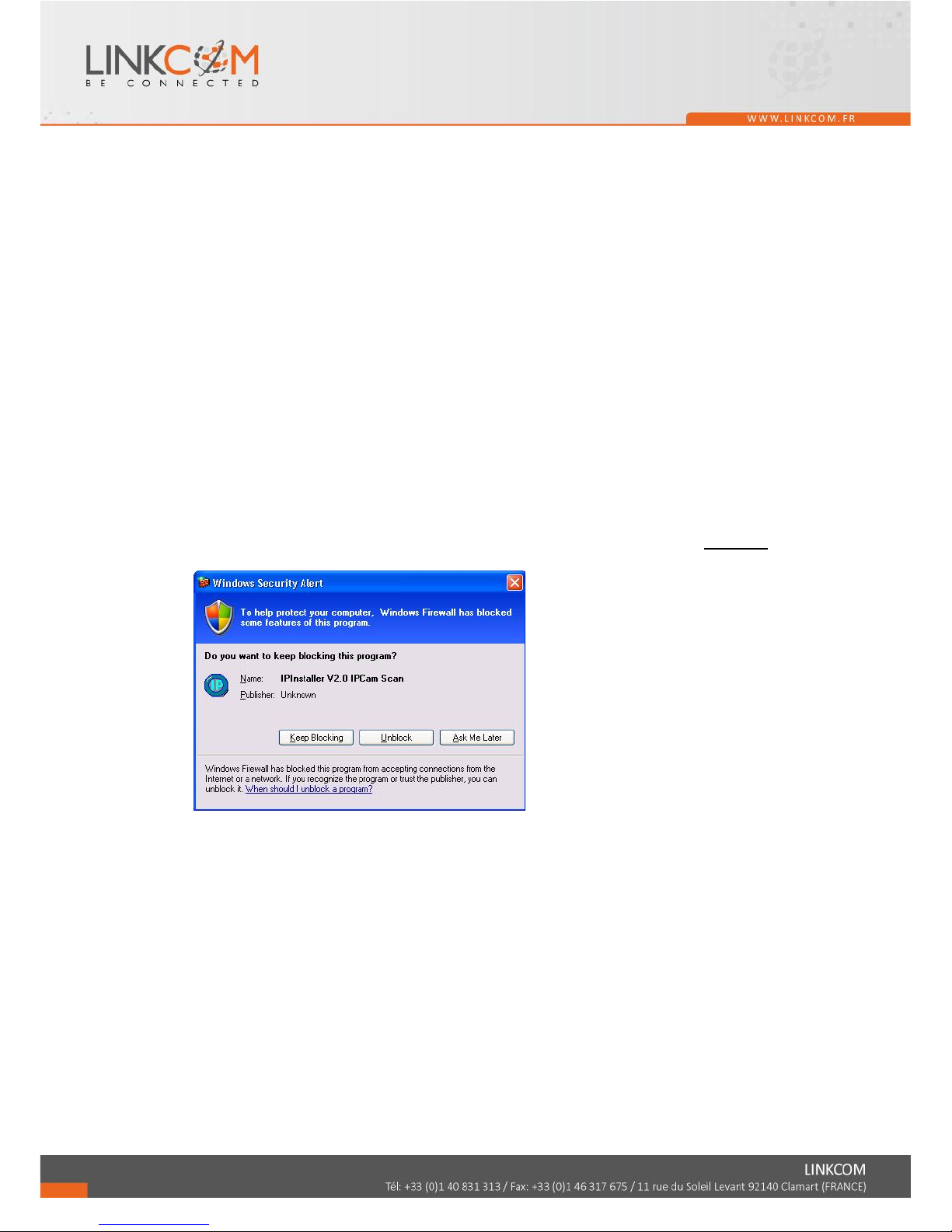
IPInstallerEng.exe to set up IP address of cameras. If OS is Windows XP SP2 or above,
the following Windows Security Alert will popup. Then, please click on Unblock.
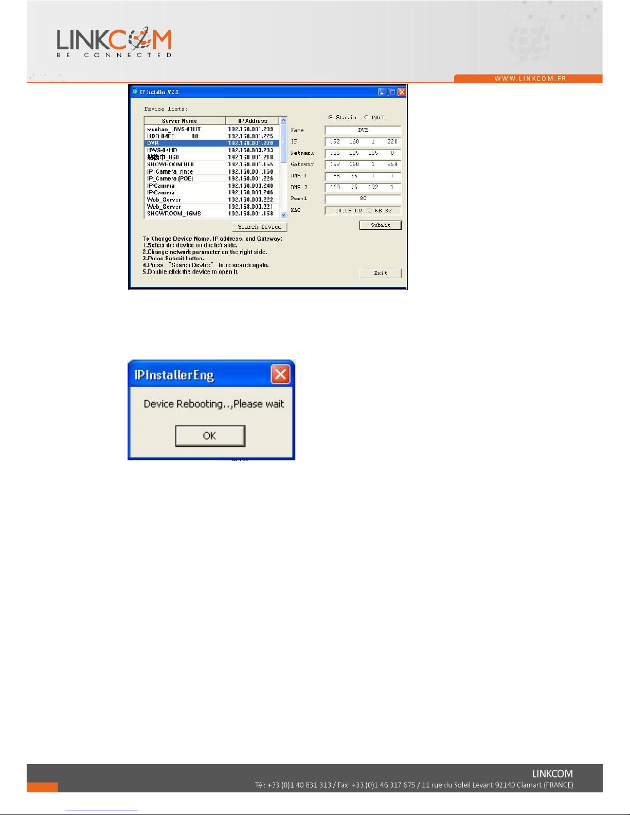
Then, IPInstallerEng.exe will popup:
NVR default IP address is 192.168.1.220
Page 59
60
NOTE: Please input correct network parameters without blank spaces.
On Device Lists, it lists all servers. Click on one server and then its IP setting will show
on the right side. After editing the parameters and clicking on Submit, the following
dialogue box will popup. And, it will reboot the device with new parameters.
Page 60
61
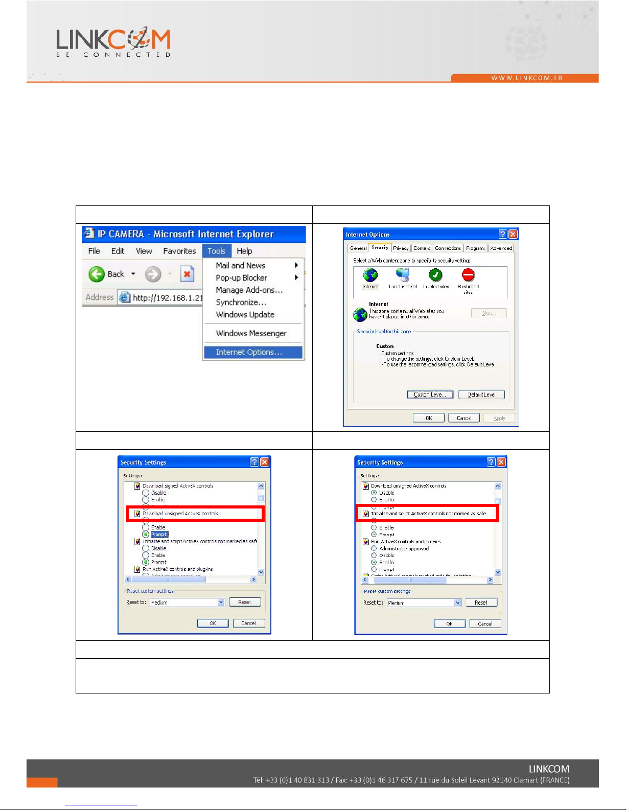
6.2 OPTIONAL MICROSOFT INTERNET EXPLORER SETUP
OPTION 1: DISABLE ACTIVEX WARNING
A. IE Tools Internet Options Security Custom Level Security Settings
Download unsigned ActiveX controls Enable or Prompt (recommend).
B. IE Tools Internet Options Security Custom Level Security Settings
Initialize and script ActiveX controls not marked as safe Enable or Prompt
(recommend).
1
2
3
4
5
Above three options are all based on select as the prompt.
As indicated in the dialogue box. Please select "YES."
Page 61
62
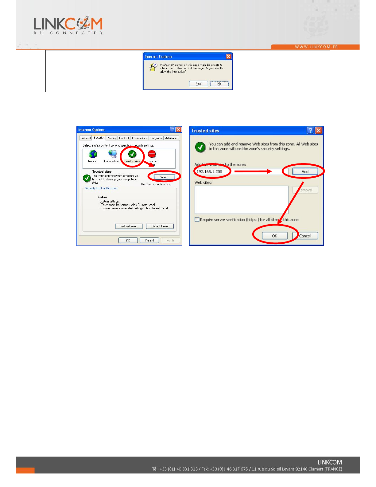
OPTION 2: ADD TO TRUSTED SITES
IE Tools Internet Options Security Trusted sites Sites
Page 62
63
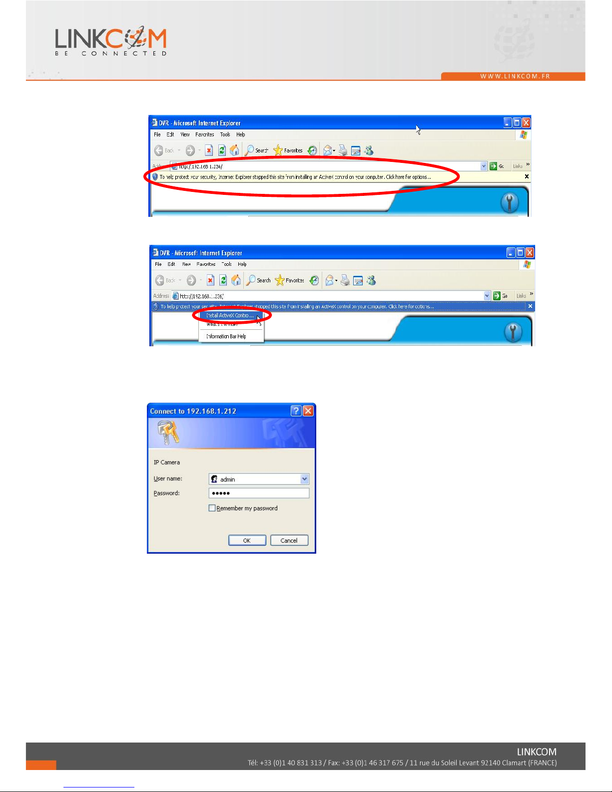
6.3 LOGIN
A. INSTALL ACTIVEX
B. START INSTALL ACTIVEX
C. ACCOUNT & PASSWORD LOGIN
After IP setup and connect to network or LAN, type IP address on IE Browser
directly. The following User name & Password Login window will popup.
Default user name: admin
Default password: admin
Page 63
6.4 REMOTE CONTROL
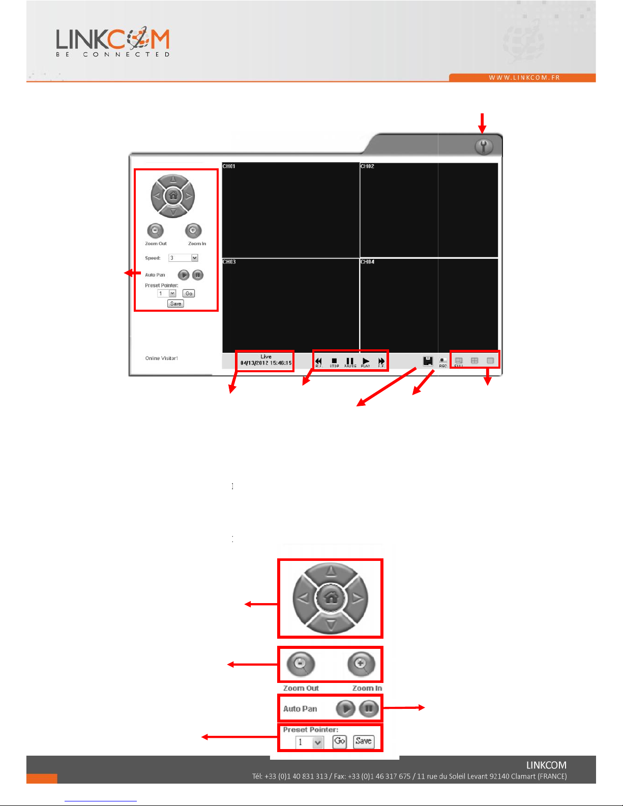
LIVE VIEWING
A. NVR Configuration
Get into NVR network menu.
B. PTZ Control
PTZ control function panel
System Time
PTZ Control
Direction Keys
PTZ Zoom in/out
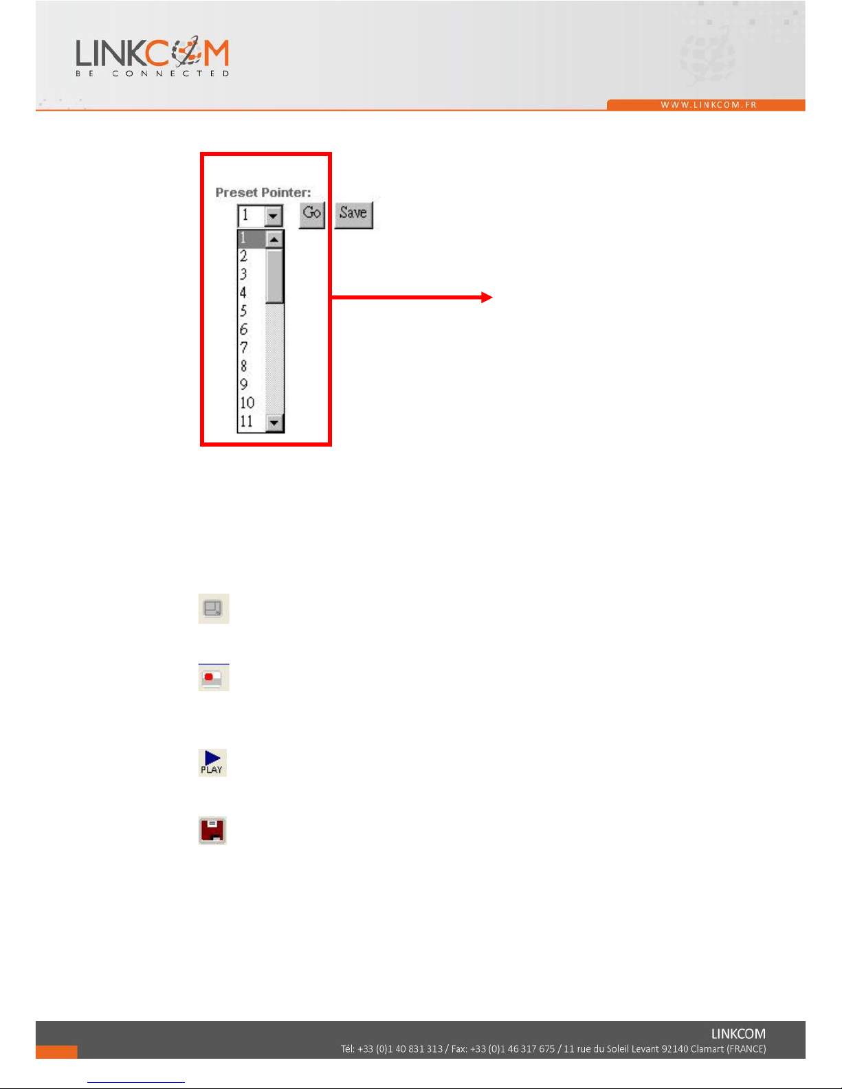
Preset Point
Setup
NVR Configuration
Play Back
REC
Time-Point Backup
Auto Pan Function
64
Screen Format
Page 64
65
C. SYSTEM TIME
Live viewing mode: The current live viewing time.
D. SCREEN FORMAT
Switch screen format and click twice to switch different channels with full screen.
E. Full Screen.
Click again to return.
F. REC.
Click to start record the live video to the PC or storage device. The saved file is *.ha0
file.
G. Playback
Click and select time playback or event playback.
H. Time-Point Backup
Click to select backup time point. The saved file is *.ha0 file.
Up to 32 preset points
for operation
Page 65
66
PLAYBACK by TIME SEARCH & EVENT SEARCH
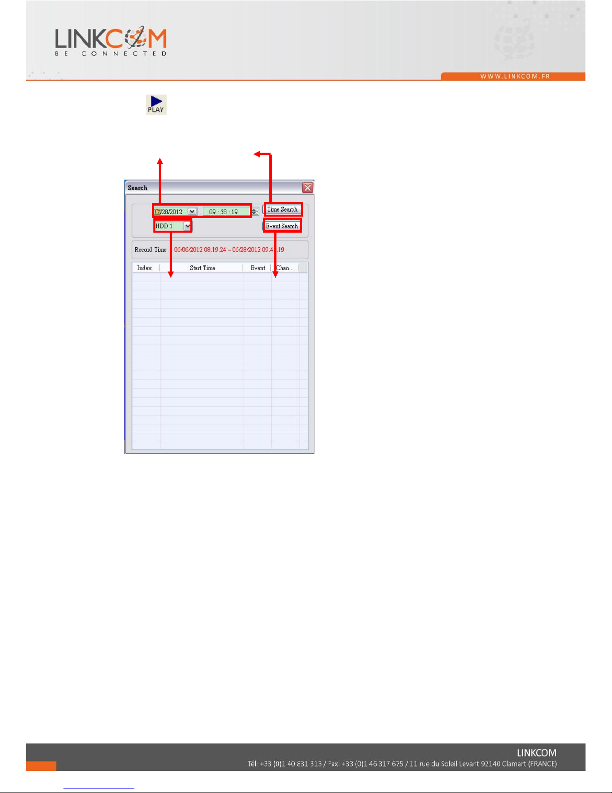
Click , and the playback window will popup
A. HDD Select
User can select HDD1 or HDD2 for playback
B. Playback Time
User can select the time then press “Time Search” for playback.
C. Time Search
User can select the time then press “Time Search” for playback.
D. Event Search
User can select event item by pressing “Event Search” for playback.
HDD Select
Event Search
Playback Time
Time Search
Page 66
67
TIME-POINT BACKUP
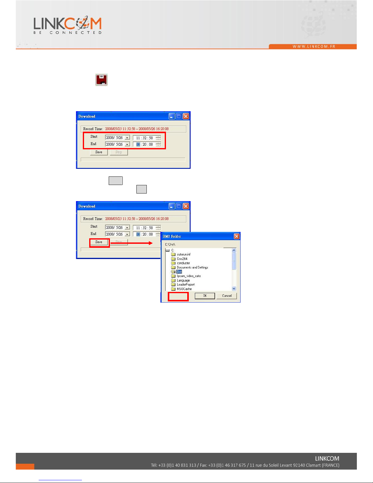
Click to operate Time-Point backup.
First, select Start and End backup time which have to among the Record Time.
Then, click Save button to select the position on PC where the user is going to backup the
data. After that, press OK button to start the backup.
Finally, double-click the left button of the mouse to open the saved backup file. The
backup file will named as the time when start to backup, such as, (20080526113258.ha0)
will be 2008/05/26 11:32:58.
Page 67
68
OTHER FUNCTIONS
User can use other functions by clicking the left of mouse
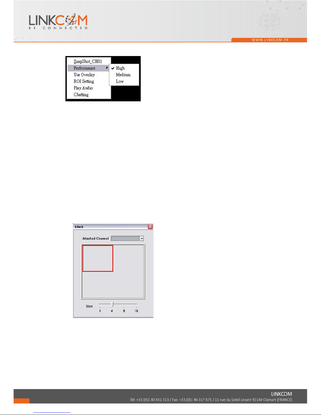
A. Snapshot:
User can save any single picture from image.
B. Performance:
User can select image quality (high, medium & low).
C. Use Overlay:
User can use Overlay function. The function can save system resource and promote
the efficacy.
D. ROI Setting
Select a normal connection or RTSP connection channel, and attach the currently set
channel to it. The attaching and attached channel can display the same live view, or
you can drag the size bar and move the red frame to adjust the square to where you
want to show on the live view.
E. Play audio:
User can play audio function by channel.
Note: remote user can receive audio from NVR. However, there’s no influence on
sound recording of playback video whether the audio is played or not.
F. Chatting
Click it to enable audio transmission from PC to the IP camera. You can connect a
microphone on PC and speak to the camera side.
Page 68
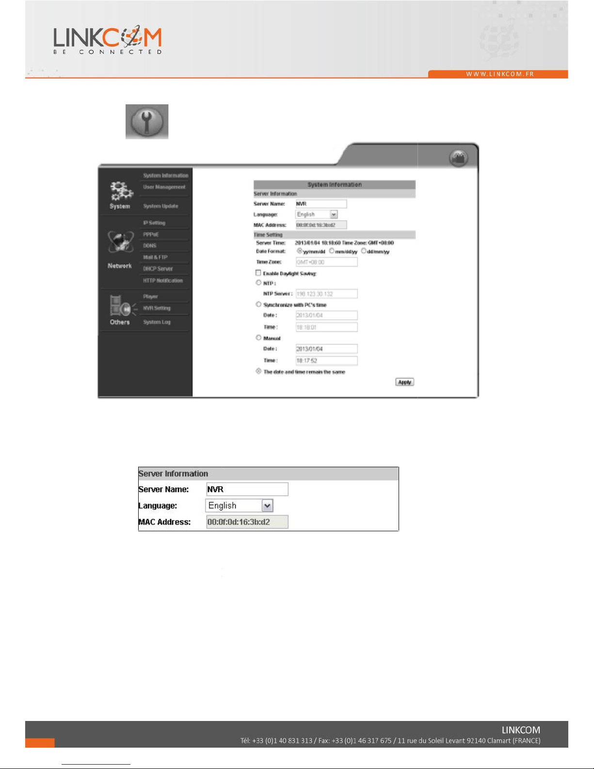
6.5 CONFIGURE
Click to go to the configuration page.
A. SYSTEM / SYSTEM INFORMATION
A-1 SERVER INFORMATION
SERVER NAME: Give the NVR name to distinguish it.
LANGUAGE: Select the language of NVR configuration page.
MAC ADDRESS: The MAC address.(cannot be revised)
69
Page 69
70
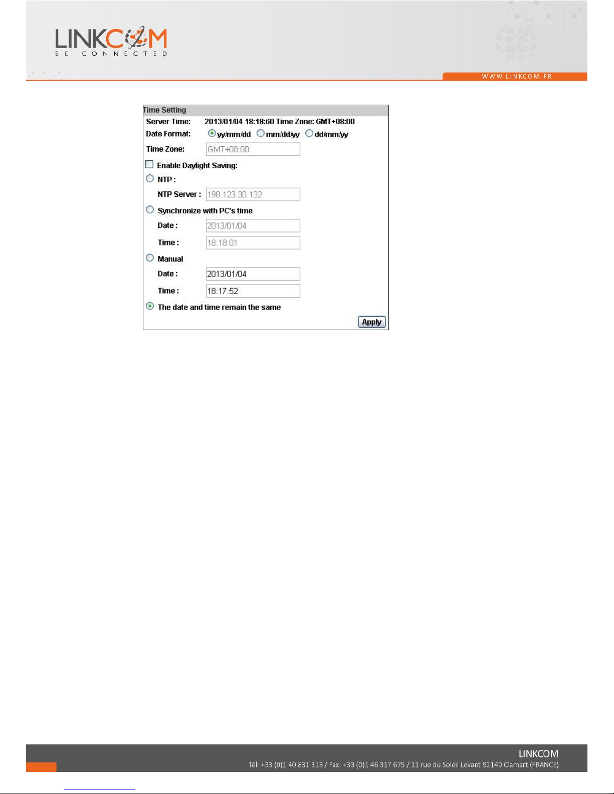
A-2 TIME Setting
Server Time: It shows current NVR server time.
Date Format: Select the date display format.
Time Zone: Select your time zone. It affects server time when you use "NTP" time.
Enable Daylight Saving:
Give the start and end daylight saving time. During daylight saving, the time will be 1
hour faster.
NTP: Key in the NTP server IP address and update interval. The NVR time will be
synchronized with NTP server time. To use this option, if the NTP Server is under
WAN, the NVR must be set to access WAN.
Synchronize with PC's time: In "Date" and "Time" column it shows your current PC
time. Click "Apply" to make the NVR time the same with PC time.
Manual: Key in the date and time, and click "Apply".
The date and time remain the same: After you select "Synchronize with PC's time"
or "Manual", and click "Apply", the selected mark will jump to this option.
Page 70
71
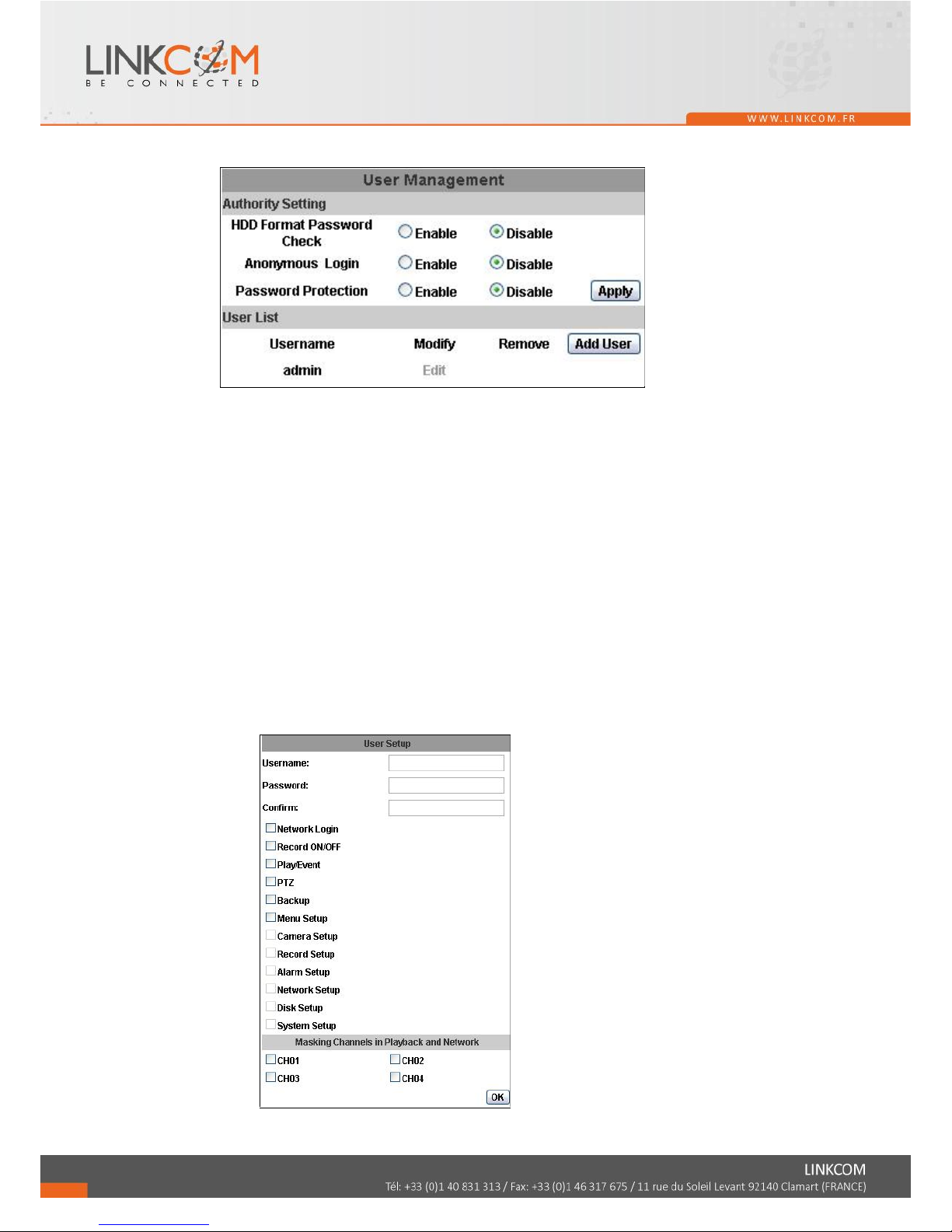
B. SYSTEM / USER MANAGEMENT
User Management provides 3 levels of limits of authority: Administrator (the
highest), User, and Guest.
Administrator: Possessing the highest level of authority to operate full functions
within network.
User: Having Live Image and Video Playback authority. Moreover, PTZ controlled
is included as well.
Guest: Only have Live Image authority.
Default administrator account: Username: admin Password: admin
B-1 AUTHORITY SETTING:
Enable or Disable those option to limit the authority.
B-2 USER MANAGEMENT:
Page 71
72
Add: Key in the Username and Password. The manager can give authority to
the new user by tick at the choice below. (Ex. Ticking at “PTZ” allows
the new user to control the PTZ). You can apply the authority setting to
the channel you choose. The new user has no authority in those channel
that are not selected.
Modify: Click Edit, then the following window will popup. After inputting
Password and Confirm Password, click on OK. You can also change
the masking channel here.
Remove: Click on selected User name on the user list and click on Remove.
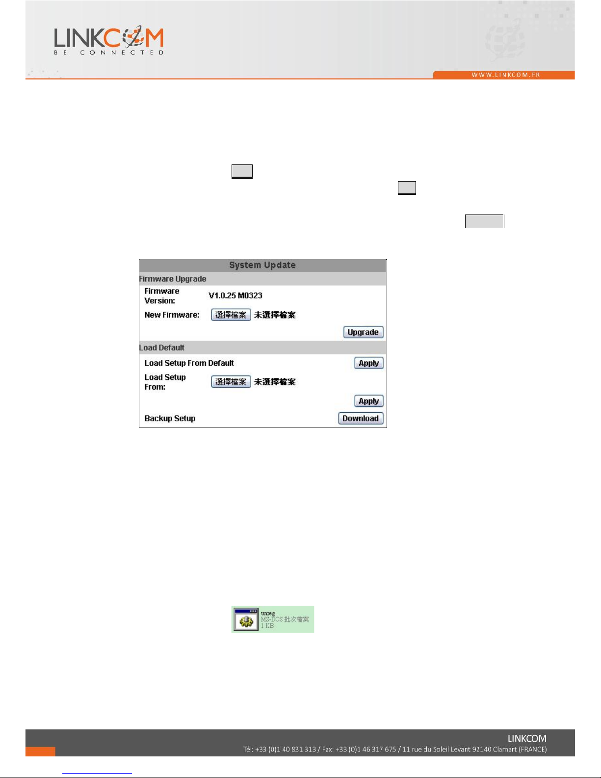
C. SYSTEM / SYSTEM UPDATE
Firmware Upgrade:
Click on the “Browse” button to select the latest firmware and then press “Upgrade”
button to upgrade the firmware.
Load Default:
Click “Browse” to choose a file. You can load setup from your computer if you ever
clicked “Download” and saved the settings before.
ActiveX Updating:
The ActiveX control should be also updated when you update the DVR/NVR
firmware. Use the tool in the attached CD to uninstall the old ActiveX control so that
the newest version can be registered.
Automatic Uninstall
Please follow the steps:
1. After updating the DVR/NVR firmware, close the web browser.
2. Run the file "unreg" in the CD to automatically remove the
existing ActiveX component "WATCH_16R" from your PC.
3. Log in the DVR/NVR via web browser again, and the browser will require
you to install the new version of ActiveX control.
Manual Uninstall
If the tool does not work, please follow the steps to uninstall ActiveX control
manually.
Page 72
73
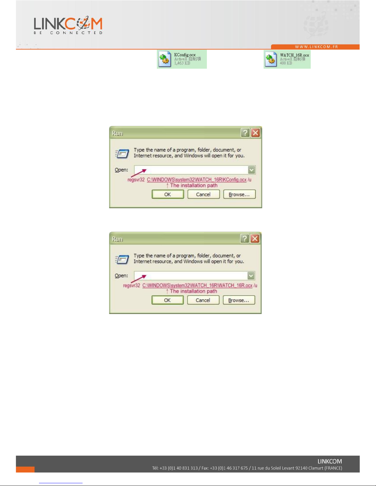
1. Look for the files "KConfig.ocx" and
"WATCH_16R.ocx" in one of the possible paths:
"C:\WINDOWS\Downloaded Program Files"
"C:\WINDOWS\W16R"
"C:\WINDOWS\system32\WATCH_16R"
2. "Start" -> "Run" -> Key in: regsvr32(The path of KConfig.ocx) /u -> Click
"OK"
Ex.: regsvr32 C:\WINDOWS\system32\WATCH_16R\KConfig.ocx /u
3. "Start" -> "Run" -> Key in: regsvr32(The path of WATCH_16R.ocx) /u ->
Click "OK"
Ex.: regsvr32 C:\WINDOWS\system32\WATCH_16R\WATCH_16R.ocx /u
4. Log in the DVR/NVR via web browser again, and the browser will require you
to install the new version of ActiveX control.
Page 73
74
D. NETWORK / IP SETTING
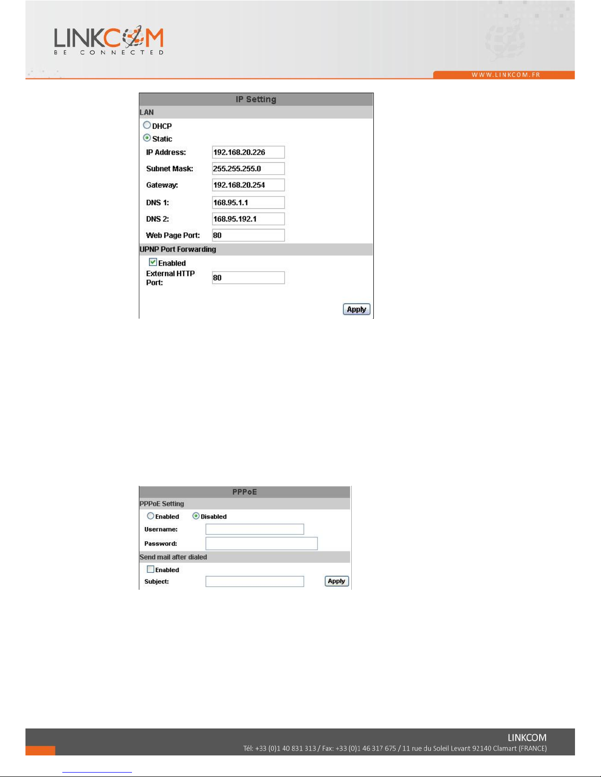
D-1 IP ASSIGNMENT
DHCP: In Dynamic Host Configuration Protocol (DHCP) mode, DHCP
server will get setting done automatically.
STATIC IP: Please input IP address, Subnet Mask, and Gateway based on
network environment.
D-2 UPNP PORT FORWARDING
When a router is used, you can enable this function to allow the user to link
the device in the intranet.
E. NETWORK / PPPoE
E-1 PPPoE SETTING
Click on Enabled to enable ADSL dial function.
Username: Username for ADSL account.
Password: Password for ADSL account.
After dialed successfully, new IP address will appear.
E-2 SEND MAIL AFTER DIALED
Click on Enabled to enable SEND MAIL AFTER DIALED function. You can
also give a subject of mail.
Page 74
75
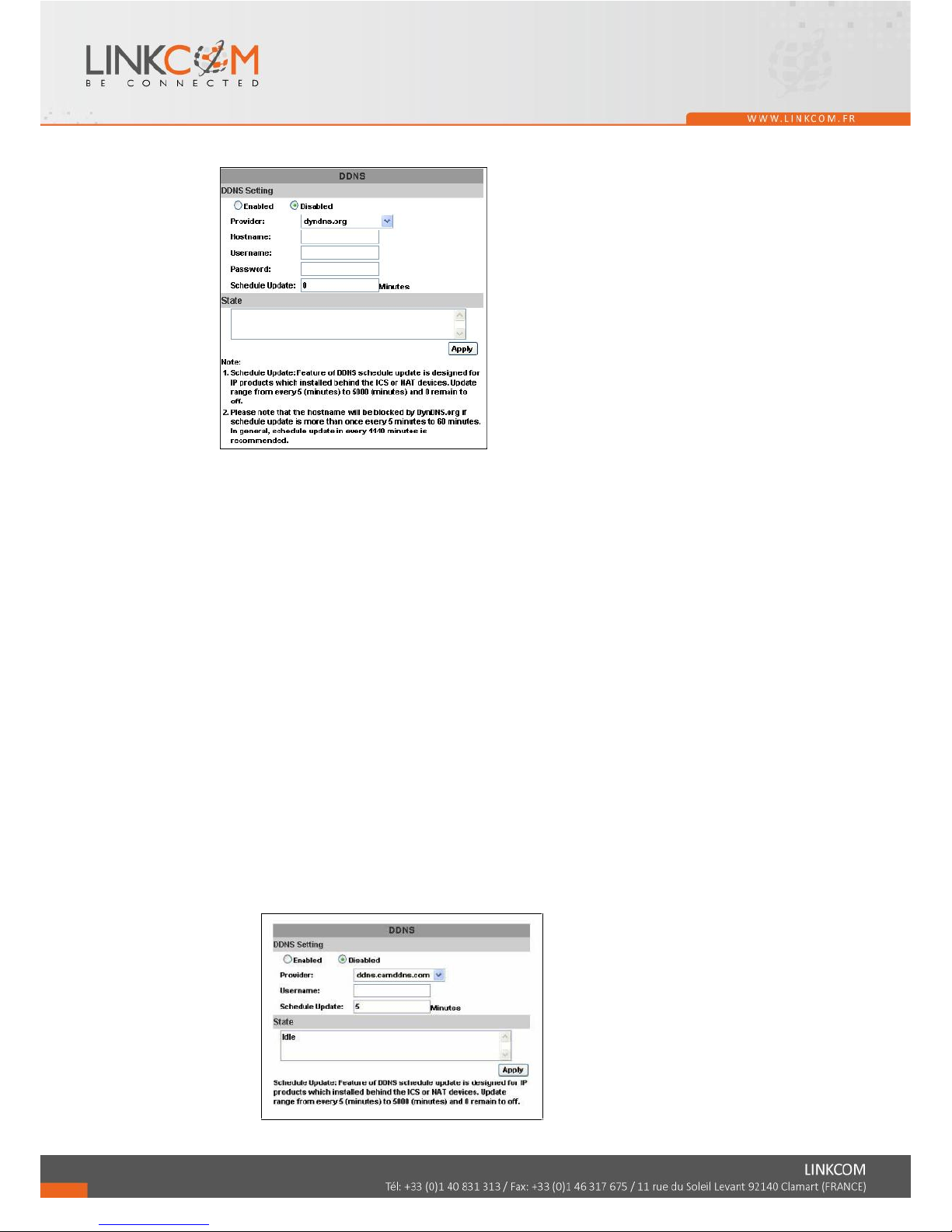
F. NETWORK / DDNS SETTING
Click on Enabled to enable DDNS function.
F-1 DYNDNS.ORG
DDNS SETTING - DYNDNS.ORG
PROVIDER: Select dyndns.org
HOSTNAME: The registered hostname in DYNDNS.ORG.
USERNAME: The registered username in DYNDNS.ORG.
PASSWORD: The registered password in DYNDNS.ORG.
SCHEDULE UPDATE: A period of time to update IP address.
STATE
1. Updating: Information update.
2. Idle: Stop service.
3. DDNS registered successfully, now log by
http://<username>.ddns.camddns.com: Registered successfully.
4. Updating Failed, the name is already registered.
5. Updating Failed, please check your internet connection.
F-2 DDNS.CAMNNDS.COM
Page 75
76
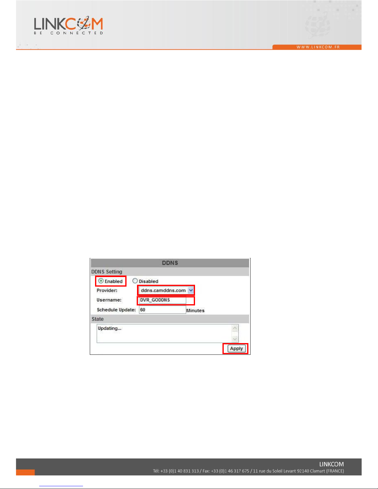
DDNS SETTING – DDNS.CAMDDNS.COM
PROVIDER: Select ddns.camddns.com
USERNAME: The registered username in DDNS.CAMDDNS.COM.
SCHEDULE UPDATE: A period of time to update IP address.
STATE
1. Updating: Information update.
2. Idle: Stop service.
3. DDNS registered successfully, now log by
http://<username>.ddns.camddns.com: Registered successfully.
4. Updating Failed, the name is already registered.
5. Updating Failed, please check your internet connection.
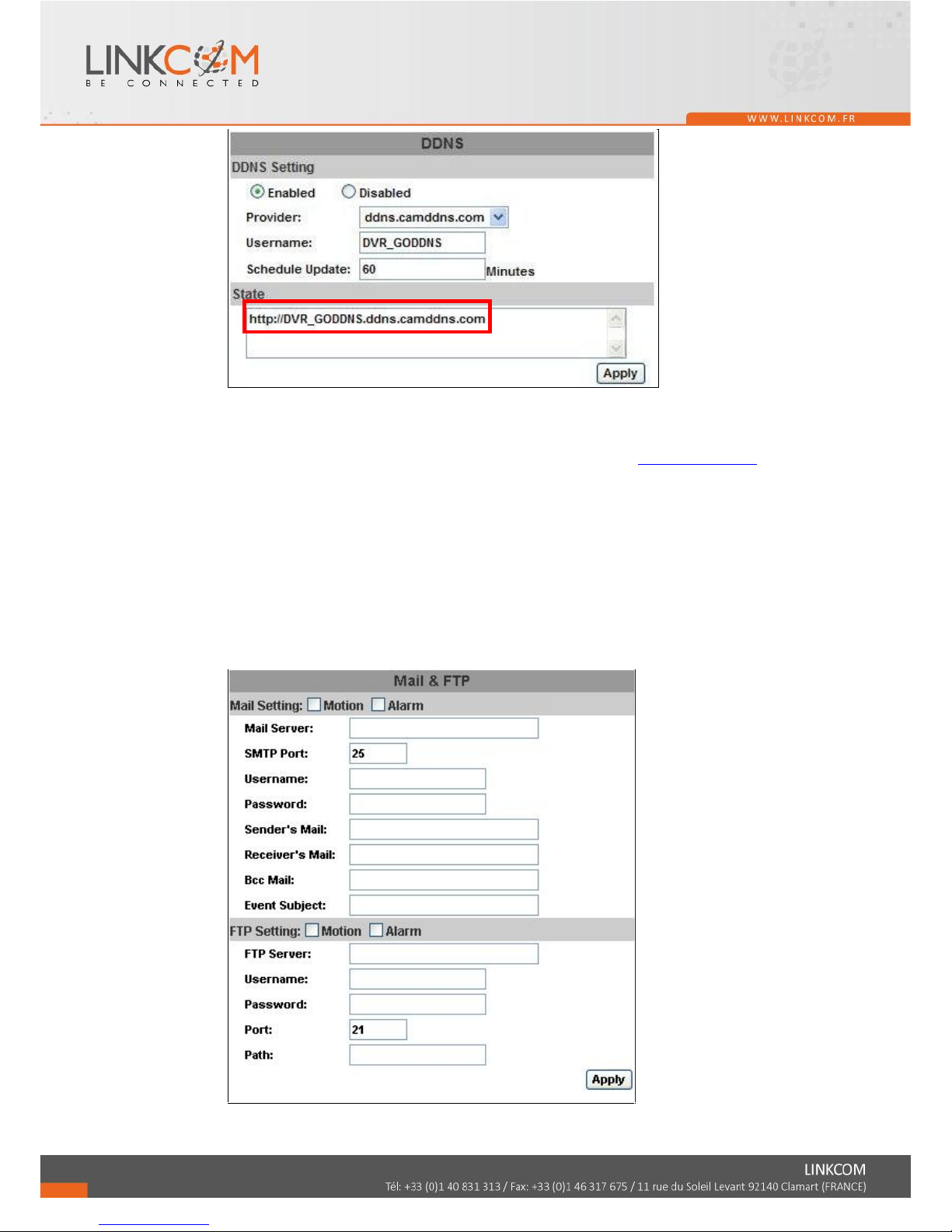
DDNS Setting Steps:
Press○1 “ENABLE” option to enable DDNS function and select○2
“ddns.camddns.com” of the provider drop down list which is suggested to use. In
the following, insert○3 the username which the user wants to apply
(i.e. NVR_GODDNS in here). After that, click○4 “Apply” button to apply a DDNS
domain name.
Finally, the NVR domain name○5 (http://NVR_GODDNS.ddns.camddns.com) will
be shown on the state block.
1.
2.
3.
4.
Page 76
77
NOTE: 1. If the user selects another provider which is ddns2.ydsNVR.com, all of the setting
steps are the same with ddns.camddns.com setting.
2. However, if dyndns.org provider is selected, please go to www.dyndns.org website
to register the account first. The user has to fill in the username, password and
hostname for applying the account. After the user applied the account successfully,
the dyndns.org will give the user a complete DDNS domain name.
3. If setting up IP schedule update too frequently, the IP may be blocked. In general,
schedule update every day (1440 minutes) is recommended.
G. NETWORK / Mail & FTP
Click on “Motion” or “Alarm” option to enable Mail Setting and FTP Setting
function.
Mail Setting: Tick “Alarm” to send video to the mail address when external alarm
5.
Page 77
78
or DI from IPCam is triggered. Tick “Motion” to send video to the mail address
when motion detection is triggered.
SMTP Port: The port of SMTP (known as Simple Mail Transfer Protocol). (Default
value is 25)
Username: The username while log in to the mail server.
Password: The password while log in to the mail server.
Sender’s Mail: The sender’s account when send the mail via this mail server.
Receiver’s Mail: The receiver’s mail address.
Bcc Mail: The receiver’s mail address for Bcc Mail.
Event Subject: The subject of this mail. (Default value is ALARM MAIL)
FTP Server: Tick “Alarm” to upload video to FTP when external alarm or DI from
IPCam is triggered. Tick “Motion” to upload video to FTP when motion detection is
triggered.
Username: The username while log in to the ftp server.
Password: The password while log in to the ftp server.
Port: The port number of file transmission. (Default value is 21)
Path: The ftp path where the user wants to reserve the information.
Finally, click on Apply button to reserve the setting.
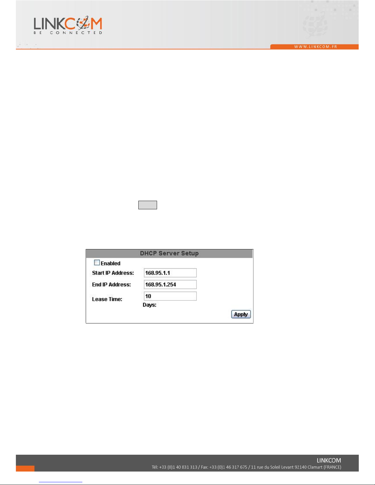
H. NETWORK /DHCP Server Setup
Give the IP address to set up the DHCP Server. The IP will change between the Start
IP and the End IP.
I. HTTP Notification
Use the checkbox to enable or disable HTTP Notification. This function allows users
to set up the CGI command to a HTTP server. The server can be any device that can
receive CGI via HTTP protocol. When alarm events happen, NVR sends CGI to that
server.
Page 78
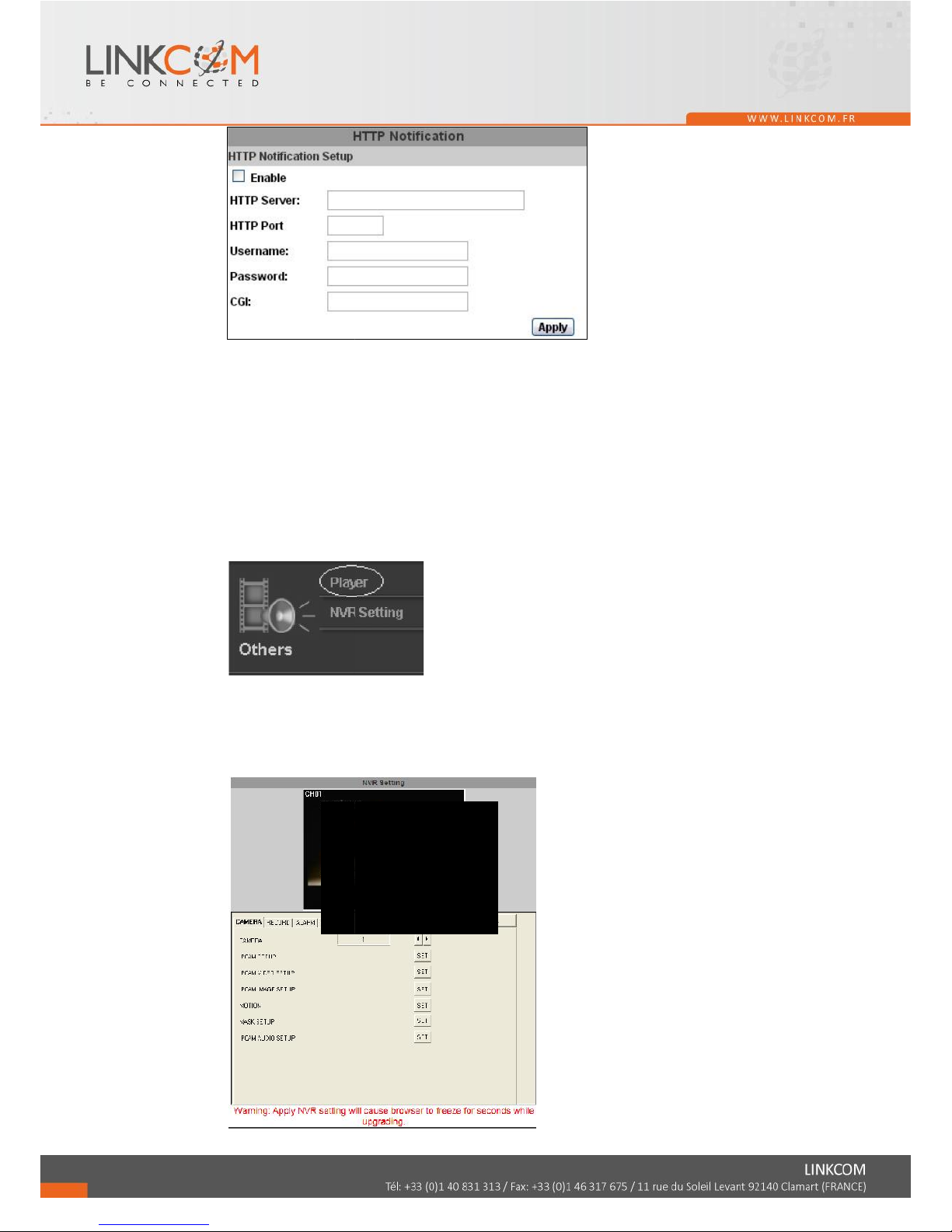
HTTP Server: Key in the server IP address.
HTTP Port: Key in the server port used for http protocol.
User Name: Key in the server username.
Password: Key in the server password.
HTTP CGI: Key in the CGI that you would like to send to the server when alarm
events happen.
J. OTHERS / Player Downloaded
Click “Player” in the left list, and your browser will start up downloading
D6Viewer.exe to your PC.
K. OTHERS/ NVR Setting
NVR setting can be changed via the Internet. Actually the settings here is the same
as what you can operate on the NVR directly.
79
Page 79
80
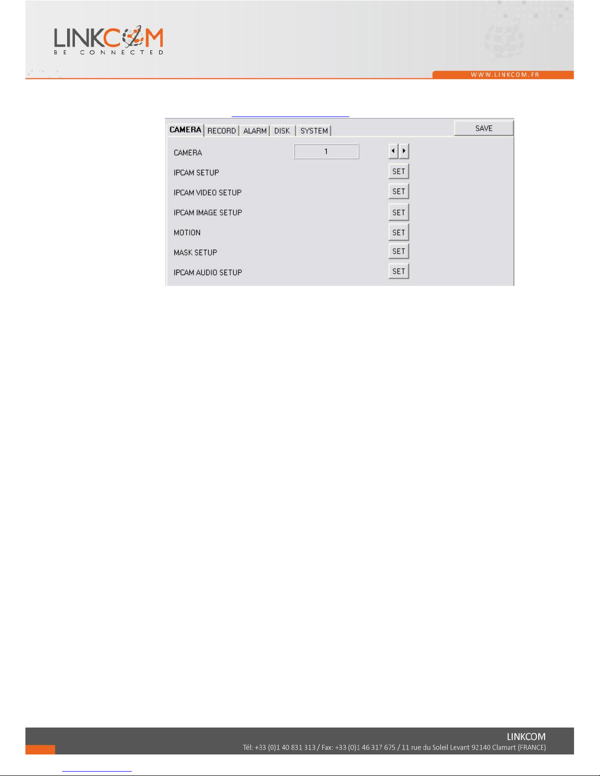
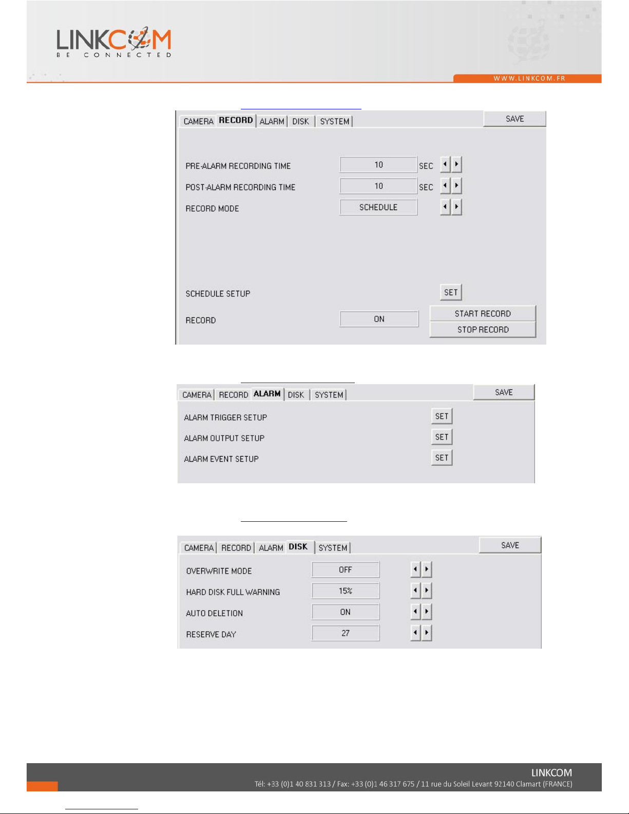
K-1 CAMERA Setting
Please refer to Chapter3.3-Camera Setup.
Page 80
81
K-2 RECORD SETTING
Please refer to Chapter3.4- Record Setup
K-3 ALARM SETTING
Please refer to Chapter3.5-Alarm Setup
K-4 DISK STEEING
Please refer to Chapter3.8-Disk Setup
Page 81
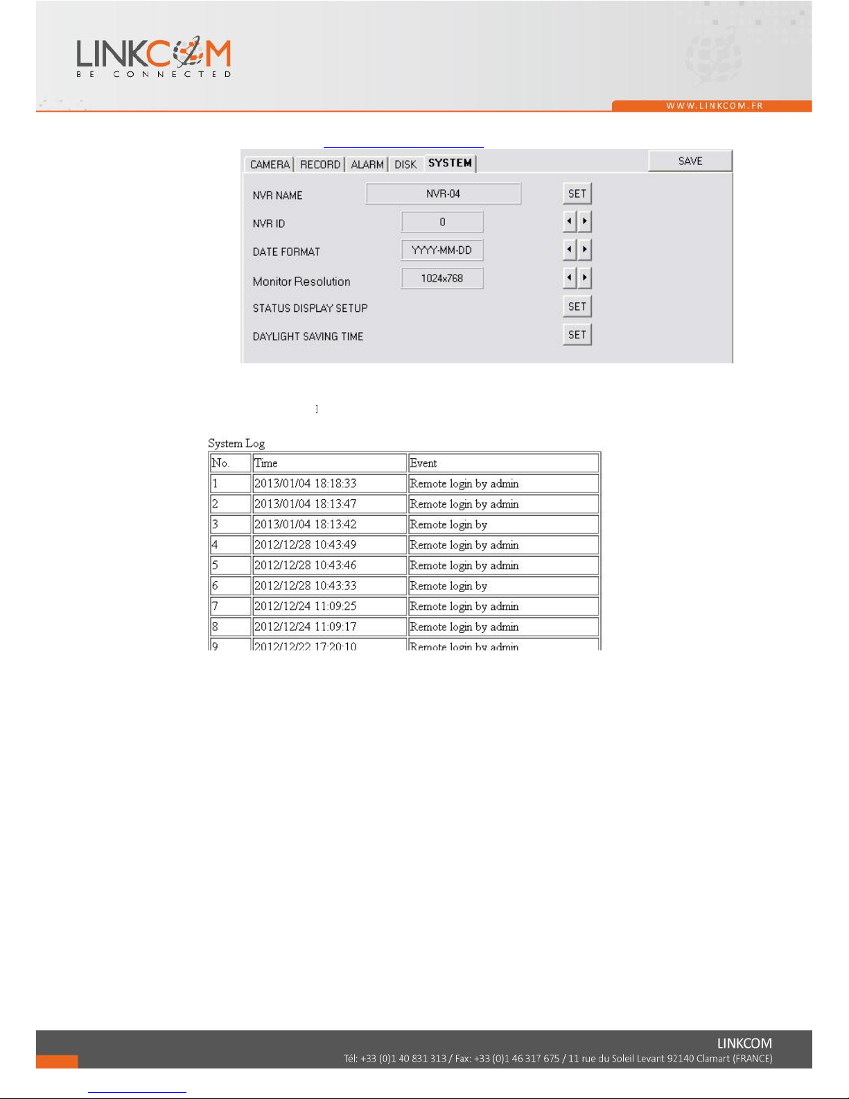
K-5 SYSTEM SETTING
Please refer to Chapter3.9-System Setup
L. OTHERS / System Log
Click to see the NVR system log.
82
Page 82
83
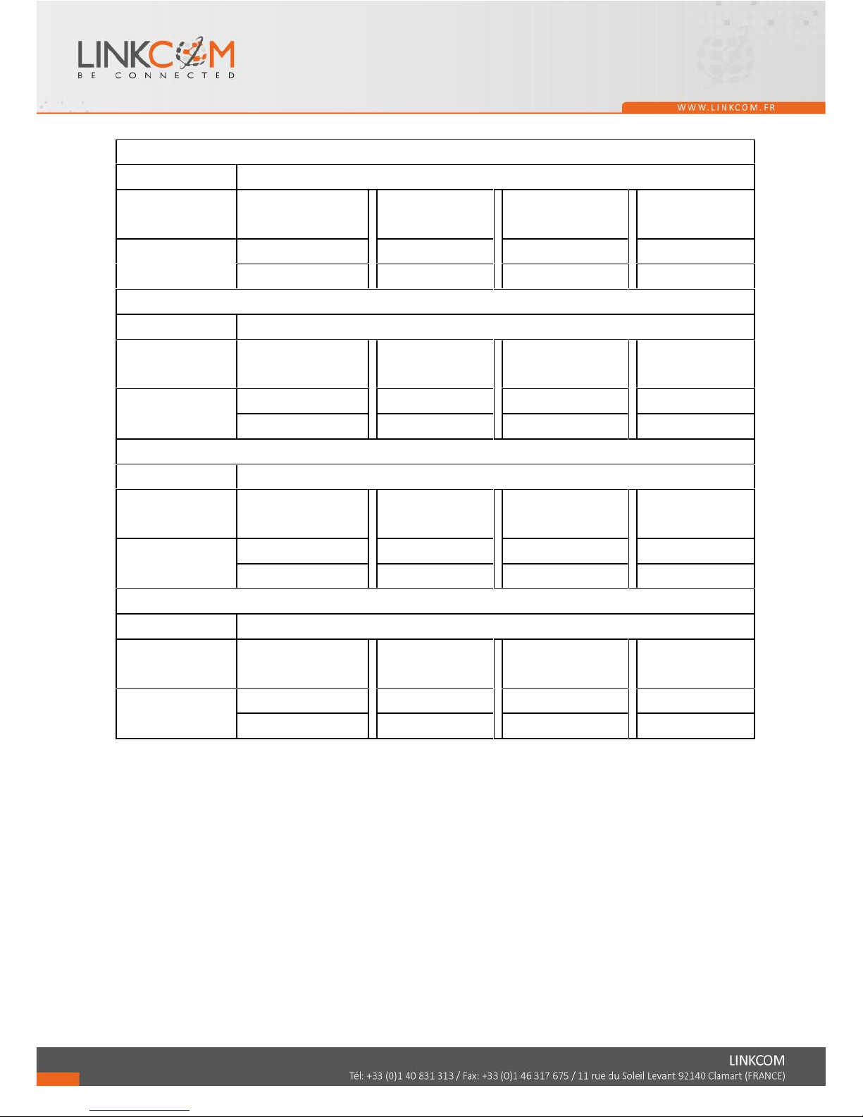
APPENDIX A: RECORDING TIME LAPSE (HOURS)
2TB UNIT:Hours
IMAGE QUALITY
(Mbps)
LOW(0.25M)
MEDIUM(0.5M)
STANDARD(1M)
HIGH(1.5M)
AVERAGE
AVERAGE
AVERAGE
AVERAGE
16CH
960
480
240
160
4TB UNIT:Hours
IMAGE QUALITY
(Mbps)
LOW(0.25M)
MEDIUM (0.5M)
STANDARD (1M)
HIGH (1.5M)
AVERAGE
AVERAGE
AVERAGE
AVERAGE
16CH
1920
960
480
320
6TB UNIT:Hours
IMAGE QUALITY
(Mbps)
LOW(0.25M)
MEDIUM (0.5M)
STANDARD (1M)
HIGH (1.5M)
AVERAGE
AVERAGE
AVERAGE
AVERAGE
16CH
2880
1440
720
480
8TB UNIT:Hours
IMAGE QUALITY
(Mbps)
LOW(0.25M)
MEDIUM (0.5M)
STANDARD (1M)
HIGH (1.5M)
AVERAGE
AVERAGE
AVERAGE
AVERAGE
16CH
3840
1920
960
640
* The value is for reference only
Page 83

84
APPENDIX B: HDD COMPATIBLE TABLE
Brand
Model
Capacity
others
SEAGATE
ST380815AS
80 GB
7200 10
ST3160815AS
160 GB
7200 10
STM3250820AS
250 GB
7200 10
ST3250310SV
250GB
SV35.3
ST3400620AS
400 GB
7200 10
ST3500320SV
500GB
SV35.3
ST3500410SV
500GB
SV35.5
ST3500320AS
500GB
7200 11
ST3500418AS
500GB
7200 12
ST3500312CS
500GB
Pipeline HD .2
ST3750640AS
750 GB
7200 10
ST3750330AS
750 GB
7200 11
ST31000333AS
1TB
7200 11
ST31000340AS
1TB
7200 11
ST31000340NS
1TB
Barracuda ES.2
ST31000340SV
1TB
SV35.3
ST31000322CS
1TB
Pipeline HD .2
ST31000525SV
1TB
SV35.5
ST31000524AS
1TB SATA3
7200 12
ST1500DL003
1.5TB SATA3
Barracuda LP
ST31500341AS
1.5TB
7200 11
ST32000542AS
2TB
Barracuda LP
ST3320620AS
320 GB
7200
ST3500413AS
500GB
7200
ST3500320NS
500GB
7200
WD
WD1600AAJS
160 GB
7200 CB
WD2500AAKS
250 GB
7200 CB
WD2500AVVS
250 GB
7200 GP
WD3200AVVS-73L2B0
320GB
7200 GP
WD5000AACS
500 GB
7200 GP
WD5000AVVS
500 GB
7200 GP
WD5000AAKS
500GB
7200 CB
Page 84

85
WD5002ABYS
500GB
7200 RE
WD
WD5000AAKX
500GB SATA3
Caviar Blue
WD5000AUDX
500GB SATA3
Green Power
WD6400AAKS
640 GB
7200 BLUE
WD6400AVVS
640 GB
7200 GP
WD7500AACS
750GB
7200 GP
WD7500AVVS
750GB
7200 GP
WD10EACS
1TB
7200 GP
WD10EADS
1TB
Caviar Green
WD10EVDS
1TB
Green Power
WD10EVVS
1TB
7200 GP
WD10EARS
1TB
Caviar Green
WD10EALX
1TB SATA3
Caviar Blue
WD10EURX
1TB SATA3
Green Power
WD15EADS
1.5TB
7200 GP
WD15EARS
1.5TB
7200 GP
WD15EURS
1.5TB
7200 GP
WD5000AVDS-63U7B0
1.5TB
7200 GP
WD15EVDS
1.5TB
7200 GP
WD20EADS
2.0TB
7200 GP
WD20EVDS-63T3B0
2.0TB
7200 GP
WD20EARS
2.0TB
Caviar Green
WD20EURS
2.0TB
7200 GP
WD30EURS
3TB
CE-GP
WD30EZRX
3TB
7200
HITACHI
HDS721616PLA380
160 GB
7200
HDT725025VLA380
250 GB
7200
HDT725032VLA360
320 GB
7200
HDP725050GLA360
500 GB
7200
HCP725050GLA380
500GB
7200
HDT721010SLA360
1TB
7200
HDS721010CLA332
1TB
7200
HDS722020ALA330
2TB
7200
HDS721050CLA362
500GB
7200
Page 85

86
APPENDIX C: ERROR MESSAGE LIST
ERROR MESSAGE
ERROR STATUS & REASON
NOTE
DISK ACCESS ERROR!
H.D.D. Data structure Un-normal.
Data does not record into NVR or bad sector on NVR H.D.D.
Please install another H.D.D. and perform the record again.
UPDATE FILE ERROR!
Please re-download the update file and update again.
FIRMWARE UPGRADE
FAILED
Please reboot the NVR and upgrade the firmware. Please send the
NVR back to repair when NVR is disability.
MEDIA ACCESS FAIL!
The USB file format is incorrect (Please format the pen drive to
FAT32) or Pen Drive is setup to ONLY READ mode (Please annul
ONLY READ mode) when reserve the data by using Pen Drive.
The data cannot be burn into CD/DVD disc. Please change another
CD/DVD disc and backup the file in CD/DVD disc storage.
NO FILE!
There is no upgrade file within Pen Drive or the name of upgrade
file does not correspond with NVR format. Please adjust the
upgrade file name based on the following information.
16CH -> UpdateN16AF.bin
09CH -> UpdateN09AF.bin
04CH -> UpdateB.bin
USB DEVICE NOT
FOUND
NO USB
Pen Drive undetected. Please Unplug the Pen Drive and plug it
again.
BACKUP START TIME
ERROR
Backup start time error.
BACKUPEND TIME
ERROR
Backup end time error.
DISK ERROR
The data cannot be burn into CD/DVD disc. Please change another
CD/DVD disc and backup the file.
FAN FAILED
Fan Error Warning.
NO LOG DATA
No Events Record.
SCHEDULE RECORD
The condition is caused by trying to stop recording when perform
the schedule record. Please setup the record to manual mode and
then stop the record.
PLEASE SELECT ONE
CAMERA
The message will be shown while using the ZOOM function under
split screen condition. Please switch the screen into full screen
mode and then operate the ZOOM function.
Page 86

87
 Loading...