

Link SmartLINK M 13 85, SmartLINK M 13 86, SmartLINK M 13 26, SmartLINK M 13 25 Operation And Installation Manual
Page 1
8,5
Operation and
Installation Manual
SmartLINK M 13 x
Page 2

Content
1 Document Content .......................................................................1
1.1 Function ...................................................................................1
1.2 Target group: Authorised personnel .........................................1
1.3 Symbols and abbreviations used .............................................1
1.4 Proper use ................................................................................2
1.5 General notes on safety ...........................................................2
1.6 Warning of misuse ....................................................................2
1.7 Disclaimer .................................................................................2
2 Product Description .....................................................................3
2.1 Type code .................................................................................3
2.2 Terms and conditions and use .................................................3
2.3 Technical data ..........................................................................3
3 Assembly .......................................................................................5
3.1 General notes on assembly ......................................................5
3.2 General notes on electrical connection ..................................10
4 Commissioning and Maintenance ............................................11
4.1 Commissioning and function test ..........................................11
4.2 Maintenance ...........................................................................11
5 Disassembly and Disposal ........................................................12
5.1 Disassembly ...........................................................................12
5.2 Disposal..................................................................................12
6 Scope of Supply .........................................................................12
7 Attachment .................................................................................13
8 Declaration of Conformity .........................................................15
8.1 Declaration of EC-conformity .................................................15
Page 3
1
1 | Document Content
1.1 Function
This operating instructions manual provides necessary information on
installation, commissioning, safe operation, disassembly and disposal.
1.2 Target group: Authorised personnel
All operations described in this operating instructions manual may only
be performed by trained professional staff authorised by the operator.
Only install and commission the SmartLINK if you have read and understood the operating instructions manual and are familiar with the
applicable regulations.
1.3 Symbols and abbreviations used
Information, tip, note:
This symbol highlights helpful additional information
Caution:
Failure to comply with this warning can lead to disorders &
malfunctions.
Warning:
Failure to comply with this warning can damage the
SmartLINK.
Power supply = PWR
Supply channel = CHL
Extension/additional modules = EXT
Input = IN
Output = OUT
White = WH
Yellow = YE
Brown = BN
Red = RD
Blue = BL
Green = GN
Switch-on time = ED
i
!
!
2
1.4 Proper Use
The products described here have been developed in order to ensure
functions as part of an overall system. It is the responsibility of the installer to ensure the correct overall functioning.
It may be used only in accordance with the following versions or for
applications approved by the installer. Detailed information on the application range can be found in the chapter „Product description“.
1.5 General notes on safety
The safety notes of the operating instructions manual and the countryspecific installation-, safety- and accident prevention regulations are
to be followed.
Residual risks are not known when observing the notes on safety and
the instructions relating to the installation, commissioning, operation
and maintenance.
1.6 Warning of misuse
In case of inappropriate or improper use or tampering, malfunctions as well as risks, e.g. due to missing signal trans-
mission, can arise for people due to the use of the SmartLINK
cable transfer. Please follow the applicable standards / guidelines (DIN
EN, VdS) in this respect.
1.7 Disclaimer
For damages or malfunctions caused by incorrect installation or failure to comply with this instruction manual, no liability is assumed. For
damages resulting from the use of spare parts or accessories not approved by the manufacturer, any further liability of the manufacturer is
excluded.
Any unauthorised repairs, modifications and additions are not permitted for reasons of safety and exclude any liability of the manufacturer
for damages resulting from this.
Page 4

2 | Product Description
2.1 Type code
This operating instructions manual is valid for the following types:
M 13 85 Guard-/ lock plate for tube frame*
M 13 86 Guard-/ lock plate for wood*
M 13 25 Lock plate / mounting box for tube frame*
M 13 26 Lock plate / mounting box for wood*
* hereinafter referred to in the operating instructions manual as
„SmartLINK“
2.2 Terms and conditions and use
The SmartLINK is intended for installation in all standard timber, PVC
and aluminium profile doors. It is used to secure the transmission of
signals and voltages of the connected components.
The SmartLINK enables domestic and commercial doors to be simply
and economically connected to power sources and signal sources,
such as fingerprint, engine locks, etc. Due to the ease of installati
on and its construction, the domestic and commercial doors can be
completely manufactured in the workshop, tested as an assembly and
accepted in the object immediately after installation.
2.3 Technical data
• Power supply 1 (PWR): 12 – 24 V DC, 3 A DC,
2 pole screw plug-in terminal, black, RM 3.5 mm,
max. core cross-section: 1.0 mm²
• Power supply 2 (CHL): 0 – 48 V DC,
5 A DC (2 sec. ED, see Fig. 2.3), 2 pole screw plug-in terminal,
black, RM 3.5 mm, max. core cross-section: 1.0 mm²
• Inputs (IN 1 – IN 4): galvanically isolated,
max. 48 V DC / 5 mA DC, 2 pole screw plug-in terminal, black,
RM 3.5 mm, max. core cross-section: 1.0 mm²
• Outputs (OUT 1 – OUT 4): galvanically isolated, max. 48 V DC /
500 mA DC, 8 pole screw plug-in terminal, black,
RM 3.5 mm, max. core cross-section: 1.0 mm²
• Operating temperature range: -20°C to +70°C
• Line connection (KÜ): LiF9Y11Y 6 x 0.34 mm², halogen-free
• Housing: Plastic (ABS), protection type IP 42
• Weight: 600 g.
3 4
8,5
322
280
300
20
4,5
Dimensions
Figure 2.3
Current / Time
Current [A]
Duration [s]
CHL
Page 5

5
268
280
19
268
280
19
R4
R4
Flügel
Rahmen
6
M 13 85
Installation in tubular frame doors
Processing of frame / leaf
• Mill long slot width 20 mm and length 268 mm,
corner radius max. 4 mm (28 mm deep)
• Pre-drill for forend screw 2x
• Cables are run through the profile
3.1 General notes on assembly
Due to the plurality of profiles and fittings available on the market, no
general information for mounting can be given since these systems
differ in several dimensions. Please check the place of installation and
the space available in the rabbet and profile area before the beginning
of assembly.
• Place of assembly: Door rabbet
• Minimum installation depth M 13 85 / 86 : 28 mm
• Minimum installation depth M 13 25 / 26 : 50 mm
• The place of installation should be chosen in such a way that the
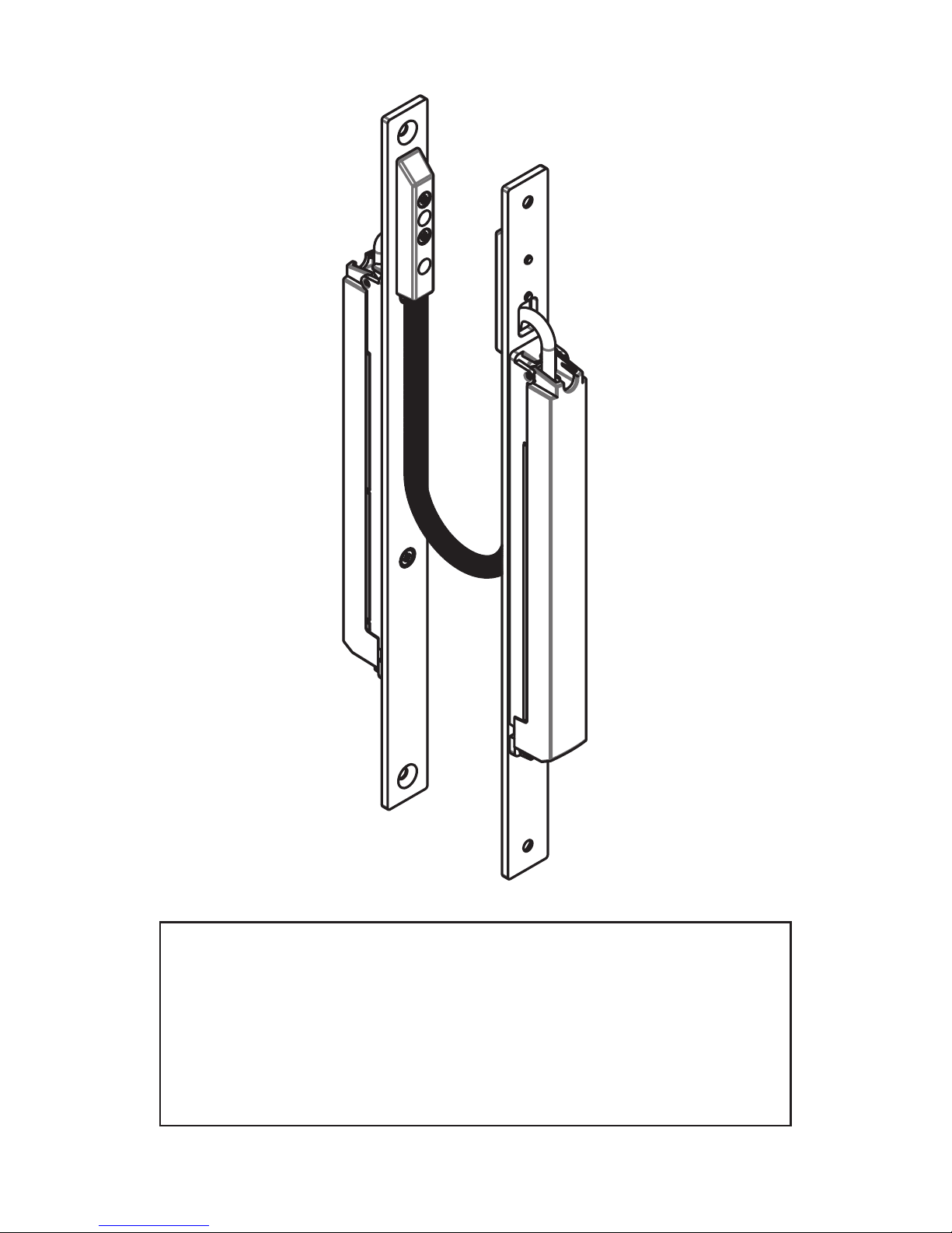
coil is not crushed when the door is closed
• The SmartLINK must be installed in a U-shape (see Fig.)
• In addition to the generally valid state of the art, the following tech nical codes are to be particularly observed:
DIN VDE 0100, VdS 2311
3 | Assembly
max. 180°
max. 90mm
max. 90mm
M 13 85 / M 13 86
M 13 85
Leaf
Frame
Page 6

max. 180°
max. 80mm
max. 80mm
M 13 25 / M 13 26
7 8
M 13 86
Installation in wooden doors
Processing of frame / leaf
•
Mill recess for lock plates radius
10 mm (3 mm deep)
• Mill recess of 19 mm width and 268 mm
length (28 mm deep)
• Drill holes for cable exit Ø16 mm
20
19
268
8
16
280
300
3
28
268
280
8
16
3
28
Flügel
Rahmen
A
A
B
B
M 13 86
268
280
19
268
280
19
R4
R4
Flügel
Rahmen
M 13 25
Leaf
Leaf
Frame
Frame
Page 7

M 13 26
Installation in wooden doors
Processing
Frame:
• Mill recess for lock plates
radius 10 mm (3 mm deep)
• Mill recess of 19 mm width and 268 mm
length (28 mm deep)
• Drill holes for cable exit Ø16 mm
Leaf:
• Mill recess for mounting box of 20 mm
width and 268 mm length, radius max.
6 mm (50 mm deep)
• Drill holes for cable exit Ø16 mm
9
3.2 General notes on electrical connection
The electrical connection may only be done in de-energised state
and by authorised personnel.
For connection examples, see attachment
10
20
26816280
50
268
280
8
16
3
28
20
R6
8
20
19
5
Flügel
Rahmen
A
A
B
B
M 13 25
Installation in tubular frame doors
Processing of frame / leaf
• Mill long slot width 20 mm and length 268
mm, corner radius max. 4 mm (28 mm deep
for lock plate, 50 mm deep for built-in box)
• Pre-drill for forend screw 2x
• Cables are run through the profile
M 13 26
Leaf
Frame
Page 8

11
4.1 Commissioning and function test
The SmartLINK is activated by turning on the supply voltage (PWR).
The master begins a scanning process for connected slave stations
(master: Status LED flashes green). Upon successful completion (master and slave 1: Status LED is green), the SmartLINK is ready for operation. If an error is detected in the scanning process (Master: Status
LED flashes red) or the communication is faulty (Master: Status LED
lights up red), all connections are to be checked and the scanning is
to be repeated upon restarting.
Should a permanent disruption of communication occur during operation (master: Status LED is red), all outputs are turned off and the
SmartLINK is to be restarted.
Short-term faults in the communication (master or slave 1: status LED
flashes red) lead to a shut-off of all outputs for the duration of the fault.
If there is no further disruption of communication (master and slave 1:
status LED is green) the operation automatically resumes.
4.2 Maintenance
When properly installed and used properly, the electronics do not
require servicing.
We recommend a regular visual and functional test is undertaken
with the following steps:
• Check SmartLINK for tightness
• Check lead, spring and housing for damage
It is recommended to clean exposed parts at least once per year
with a soft, dry cloth. Never use oil or silicone-containing lubricant or
cleaning agent.
Damaged or defective equipment are to be replaced.
4 | Commissioning and Maintenance 5 | Disassembly and Disposal
12
!
5.1 Disassembly
The SmartLINK is to be dismantled only in de-energised state.
The dismantling of the screw plug-in terminals must be done in
accordance with Fig. 5.1 with a screwdriver.
Fig. 5.1
5.2 Disposal
The SmartLINK is to be disposed of professionally in accordance
with the national regulations and laws.
6 | Scope of Delivery
1 pc. Cable transition SmartLINK M 13 x
1 pc. Installation manual SmartLINK M 13 x
1 accessories kit for electronics in the PE-bag
2 pcs. Screw plug-in terminal RM 3.50 pluggable, 8-pole, no. 1 – 8
2 pcs. Screw plug-in terminal RM 3.50 pluggable, 8-pole no. 9 – 16
4 pcs. Screw plug-in terminal RM 3.50 pluggable, 2-pole
2 pcs. Cable ties 2.5 x 100 mm
1 accessories kit for attachment in the PE-bag
4 pcs. Tapping screw countersunk, Pozi DIN 7982 PZ C 3.5 x 50, A2
4 pcs. Tapping screw countersunk, Pozi DIN 7982 PZ C 3.5 x 25, A2
4 pcs. Countersunk screw, Pozi DIN 965 PZ M4 x 8, A2, 7046-1M
Page 9

13
7 | Attachment
Connection example: Power supply
+
-
PWR
12V - 24V
=
Optional
1
2
CHL
=
12V - 48V
+
-
PWR
Load
Optional
1
2
CHL
Load
Note:
The correct polarity of the voltage PWR is to be ensured!
The CHL connection is optional and can be freely assigned.
Master:
Slave 1:
Connection example: Schematic diagramm
Control signals
Control signals
Control signals
Control signals
Voltage
Voltage
14
+
-
PWR
12V - 24V
=
+
-
IN
Signal transmitter
+
-
CHL
12V - 48V
=
+
-
IN Signal transmitter
+
-
IN
Input switching 1:
Loop through the
voltage PWR
Connection example: Input switching (valid for the inputs IN1-8)
Master:
Slave 1:
Note:
The correct polarity of the inputs must be ensured!
The input switching can be freely selected for each input (IN 1-8).
Input switching 2:
Loop through the
voltage CHL
Extern
12V - 48V
Input switching 3:
Applying an external
voltage
Optional
+
-
PWR
12V - 24V
=
+
-
OUT Load
+
-
CHL 12V - 48V
=
+
-
OUT
Load
+
-
OUT
Output switching 1:
Loop through the
voltage PWR
Connection example: Output switching (valid for outputs OUT1-8)
Master:
Slave 1:
Note:
The correct polarity of the outputs is to be ensured!
The output switching can be freely selected for each output (IN 1-8).
Output switching 2:
Loop through the
voltage CHL
Extern
12V - 48V
Output switching 3:
Loop through an
external voltage
Optional
Page 10

15
8.1. EC Declaration of Conformity
8 | Declaration of Conformity
16
Page 11

LINK GmbH
D - 35510 Butzbach
Telephon: +49 (0) 6033-97404-0
Fax: +49 (0) 6033-97404-20
E-Mail: info@link-gmbh.com
Internet: www.link-gmbh.com
Specifications subject to change without notice. MA0002062 Stand: 4416
 Loading...