

Page 1
MX44-4KUHDE
Page 2
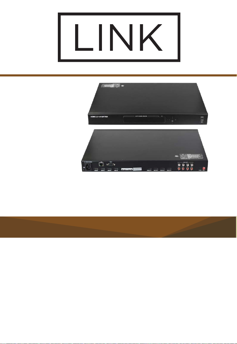
HDMI 2.0 4:4 Matrix
User Manual
Version: V1.0.0
Page 3

Important Safety Instructions
Page 4

Warnings of FCC
This equipment has been tested and found to comply with the limits for a Class
B digital device, pursuant to Part 15 of the FCC Rules. These limits are
designed to provide reasonable protection against harmful interference in a
residential installation. This equipment generates uses and can radiate radio
frequency energy and, if not installed and used in accordance with the
instructions, may cause harmful interference to radio communications.
However, there is no guarantee that interference will not occur in a particular
installation. If this equipment does cause harmful interference to radio or
television reception, which can be determined by turning the equipment off
and on, the user is encouraged to try to correct the interference by one or more
of the following measures:
-- Reorient or relocate the receiving antenna.
-- Increase the separation between the equipment and receiver.
-- Connect the equipment into an outlet on a circuit different from that to
which the receiver is connected.
-- Consult the dealer or an experienced radio/TV technician for help.
Changes or modifications not expressly approved by the party responsible for
compliance could void the user's authority to operate the equipment.
Table of Contents
Introduction ...................................................................................................... 2
Features ................................................................................................... 3
Package Contents .................................................................................... 3
Specifications ................................................................................................... 4
Panel Description ............................................................................................. 6
Installation and Wiring...................................................................................... 8
Installation ................................................................................................ 8
Wiring ....................................................................................................... 8
Front Panel Control ........................................................................................ 11
IR Remote Control ......................................................................................... 12
Page 5

EDID Management ........................................................................................ 13
API Command Control ................................................................................... 15
Telnet Control .................................................................................. 15
RS232 Serial Control ....................................................................... 17
Web UI Control .............................................................................................. 18
Access the Web Interface ....................................................................... 18
Matrix Control ......................................................................................... 19
General Setting ....................................................................................... 20
Advanced Setting ................................................................................... 26
Warranty Terms and Conditions ..................................................................... 30
Page 6

Introduction
MX44-4KUHDE is a 4x4 HDMI Matrix with resolutions supported up to
4K@60Hz 4:4:4 8bit and HDCP 2.2 compatibility. It allows four sources to be
distributed or switched to four HDMI displays simultaneously. MX44-4KUHDE
also provides de-embedded analog audio output from each HDMI output.
MX44-4KUHDE Matrix can be controlled by front panel buttons, IR, RS232
and LAN control with Telnet API and Web UI. Independent DIP switches are
also provided for advanced EDID management.
Designed for 1U rack mount and stand-alone installation, this matrix offers an
Ultra HD A/V switching and distribution solution ideal for a variety of
applications, such as offices, schools, conference rooms, hotels, etc.
Page 7

Features
Technical
Includes 4 HDMI inputs and 4 HDMI outputs
Inputs and outputs support video resolutions up to 4K@60Hz 4:4:4 8bit
and HDCP 2.2
Supports 4K HDR
Fast switching among multiple video sources
Supports L/R analog audio de-embedding outputs from each HDMI
output
Supports front panel buttons, IR, RS232 and LAN (Telnet API & Web UI)
control options
Supports API command control through RS232 and Telnet connection
Independent DIP switches for manual EDID management
Package Contents
MX44-4KUHDE Matrix x 1
IR Remote Handset x 1
USB to UART Cable x 1
AC Power Cord (with US Plug) x 1
Mounting Bracket (with screws) x 2
Specifications
Page 8

Input/Output Connections
4 x HDMI IN
4 x HDMI OUT 4
4 x AUDIO OUT
1 x IR EXT.
1 x LAN
1 x RS232 DB9 port
1 x AC IN
Input/Output Video Type
HDMI with HDR, HDCP 2.2
Input/Output Resolution
Supported
800x6008, 848x4808, 1024x7688, 1280x7688,
1280x8008, 1280x9608, 1280x10248,
1360x7688, 1366x7688, 1440x9008, 1600x9008,
1600x12008, 1680x10508,
1920x12008, 2048x11528, 3840x2160
2,3,5,8
,
4096x2160
2,8
720x4808 (480p), 720x5766 (576p), 1280x7206
(720p50), 1280x7208 (720p60), 1920x10806
(1080p50), 1920x10808 (1080p60)
1 = at 23.98 Hz, 2 = at 24 Hz, 3 = at 25 Hz, 4 = at 29.97
Hz, 5 = at 30 Hz, 6 = at 50 Hz, 7 = at 59.94 Hz, 8 = 60 Hz
Audio Format
HDMI: Fully supports HDMI audio formats
in HDMI 2.0 specification;
L/R Analog AUDIO OUT: PCM 2.0
Control
Control Method
Front panel button, IR, RS232, LAN (Telnet API
& Web UI)
Page 9

General
Operating
Temperature/RH
32°F ~ 113°F (0°C ~ 45°C)
10% ~ 90%, non-condensing
Storage Temperature/RH
-4°F ~ 158°F (-20°C ~ 70°C)
10% ~ 90%, non-condensing
ESD Protection
Human-body model:
±8kV (air-gap discharge)/
±4kV (contact discharge)
Power Supply
AC 100~240V 50/60Hz
Power Consumption
(Max)
1018P: 22W; 4K: 27.50W
Dimensions (W x H x D)
440mm x 300mm x 43.5mm/
17.32" x 11.81" x 1.71"
Product Net Weight
3.58kg/7.89lb
Rack Space Required
1U
Certification
CE, FCC
Range
Supported Video
HDMI
Input/Output: 49ft/15m
1080P@60Hz
Input: 16ft/5m
Output: 33ft/10m
4K@60Hz 4:2:0 8bit with
HDR
Input: 10ft/3m
Output: 16ft/5m
4K@60Hz 4:4:4 8bit with
HDR
Cable Specification:
Cable Type
Page 10
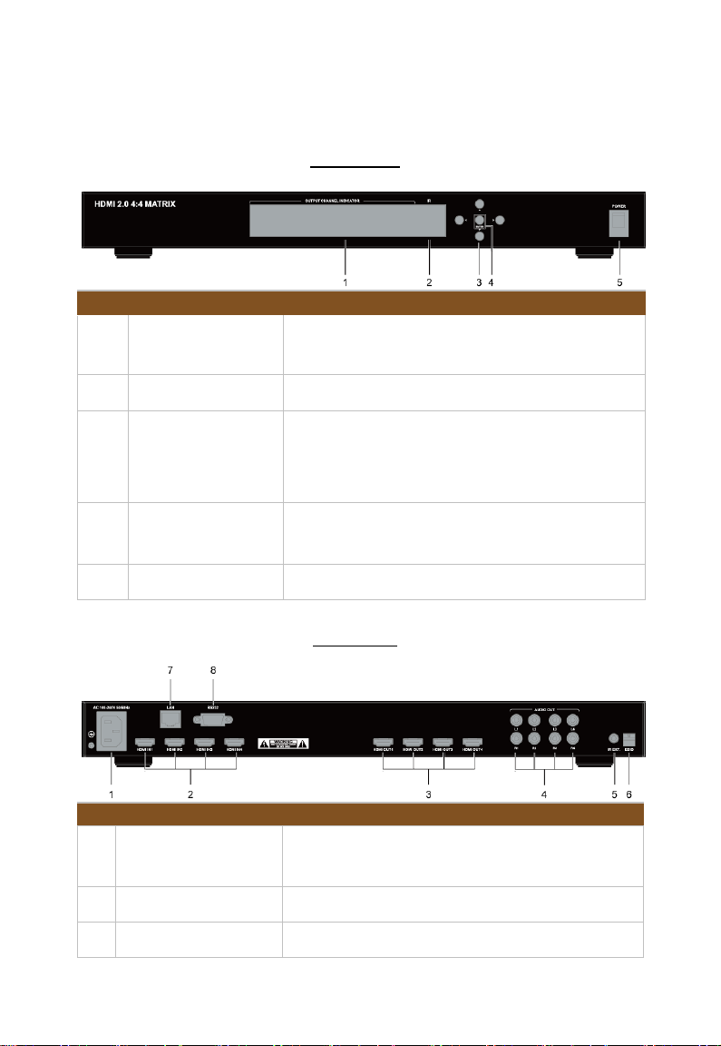
Panel Description
No.
Name
Description
1
Output Channel
Indicator
Indicates input for output port 1-4.
2
IR Window
Receives signals from IR Remote.
3
Selection Buttons
Selects input and output channels.
Left/Right: press to select output channels.
UP/Down: press to select input channels.
4
Enter Button
Press to implement the input and output
selection.
5
Power Switch
Press to turn on or off the matrix.
ID
Name
Description
1
AC
Accepts AC power of 100-240V 50/60Hz.
Connect the power cord provided.
2
HDMI IN 1-4
Connect to HDMI source devices.
3
HDMI OUT 1-4
Connect to HDMI display devices.
Front Panel
Rear Panel
Page 11

4
AUDIO OUT 1-4
For de-embedding L/R analog audio output.
Connect to audio devices via RCA stereo audio
cables.
5
IR EXT.
IR extension port. Connect an IR receiver cable
if required.
6
EDID DIP Switch
For EDID Management.
7
LAN
RJ45 port; connect to a control system for Web
UI and Telnet Control.
8
RS232
DB9 port; connect to a control system for RS232
control.
Page 12
Installation and Wiring
Installation
Note: Before installation, please ensure the device is disconnected from the
power source.
MX44-4KUHDE occupies 1U space and can be placed on a solid and stable
surface or installed on a standard rack mount.
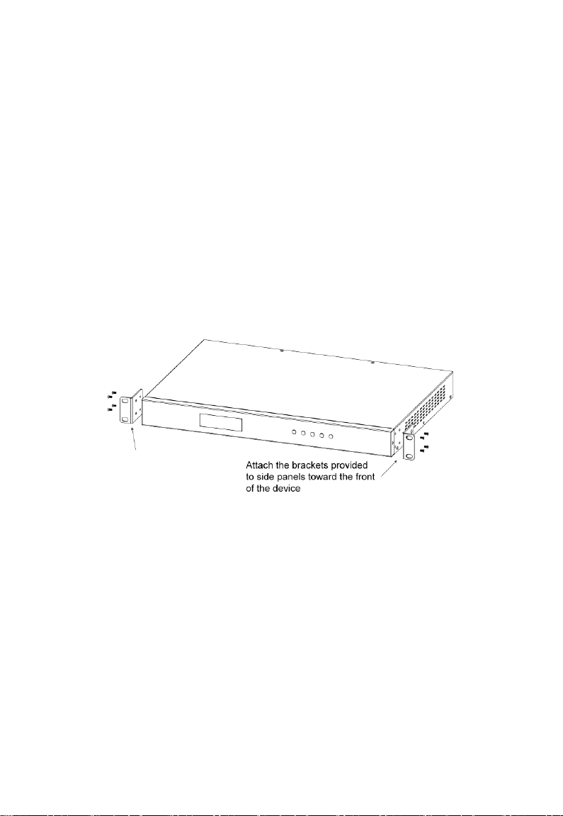
Steps for installing the matrix on a rack mount:
1. Position and install the mounting brackets with the mounting screws
provided.
2. Mount and affix the matrix in the rack mount with the mounting screws.
Wiring
Before wiring, please ensure the unit is disconnected from power. Otherwise,
circuitry damage or physical injury may occur.
Steps for device wiring:
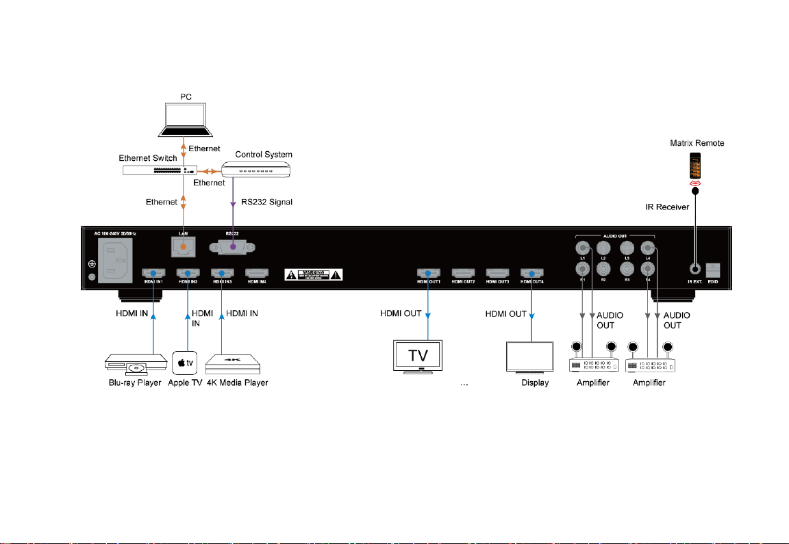
1. Connect HDMI IN
Page 13

Connect HDMI source devices to HDMI IN 1-4 of the matrix with highquality HDMI cables (e.g. Blu-ray player, PC, game console, Apple TV,
etc.)
2. Connect HDMI OUT
Connect HDMI display devices to HDMI OUT 1-4 of the matrix (e.g. TV,
projector, LED/LCD display, etc.)
3. Connect AUDIO OUT
Connect audio devices to AUDIO OUT 1-4 of the matrix (e.g. audio
amplifier) with RCA stereo cables.
4. Connect for additional control options:
a) IR Control: The matrix can be controlled through IR signal by
pointing the IR remote provided at front panel IR window directly.
Alternatively, connect an IR receiver (38KHz) to IR EXT. of the
matrix for IR extension, and have its head secured in a place
accessible to the matrix remote.
b) RS232 Control: Connect a control PC or control system to RS232
of the matrix.
c) LAN (Web UI/Telnet) Control: Connect the control PC or control
system's network to the matrix through LAN port.
5. Connect the power
Connect the AC power cord provided and switch on the power button.
6. Power on all devices.
Note:
Before plug or unplug any cable, please power off the matrix firstly.
When turning on and off the system, please follow the rule "first off, last
on".
Page 14
Page 15

Page 16
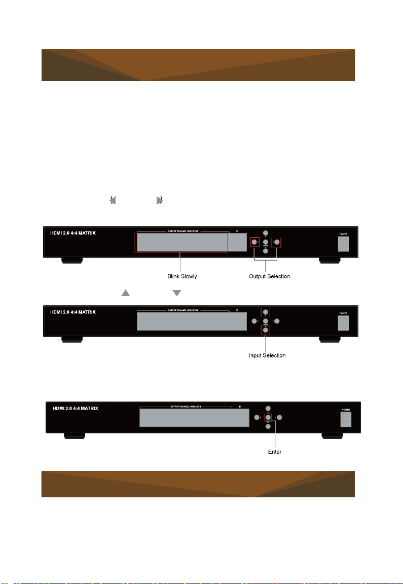
2 .Press the up (
)
or down
( ) button to select input channel.
Front Panel Control
The front panel of the MX44-4KUHDE matrix features a LED screen to display
the mapping status from each input to each output channel.
Power on the matrix and wait until the front panel LED screen shows "1234"
in red. Then the matrix is ready for operation. You can select input from 1 to 4
for each output via front panel buttons.
For example, to select input source for output display:
1. Press the left ( ) or right ( ) button to select output channel. Then the LED
will blink slowly to show the selected output channel.
3. Press the Enter button to implement above selection. The LED will stop
blinking when the selection takes effect.
IR Remote Control
You can switch among multiple inputs for each output display by pointing the
matrix IR remote directly at the IR window on the front panel or the IR
extension cable connected to the rear panel.
Page 17
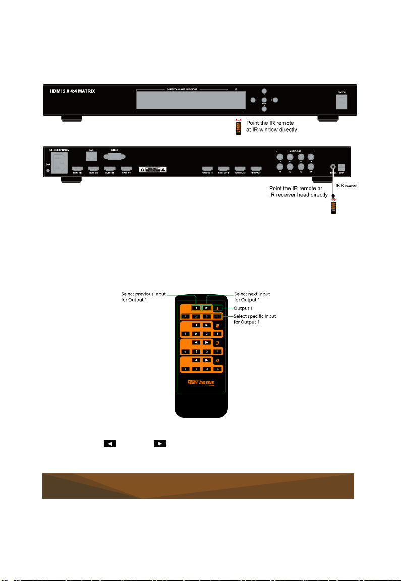
Steps for IR Remote operation:
previous (
)
or next
( ) button.
1. Operate as shown in the diagrams below, using the IR remote.
2. Locate the target output you want to switch inputs for on the remote,
numbered 1-4 vertically along the right side.
3. Press the desired input number to select the corresponding input source
for your target output.
4. To cycle through multiple inputs for your target output, press the
EDID Management
Page 18
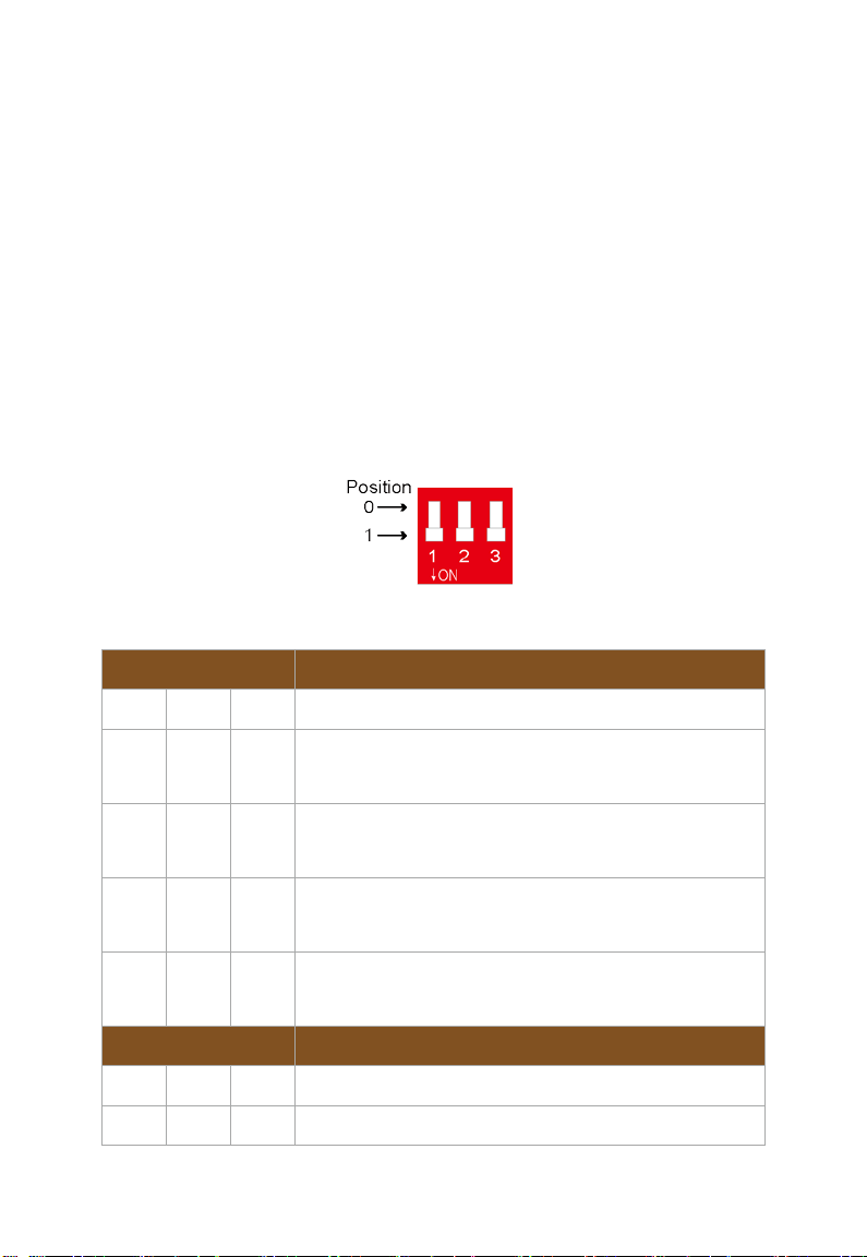
EDID (Extended Display Identification Data) is a data structure generated by
Function
0 0 0
EDID controlled by Front Panel, Web UI or API
0 0 1
Set 4K@60Hz HDR with stereo audio as EDID
(Smart EDID OFF)
0 1 0
Set 4K@30Hz HDR with stereo audio as EDID
(Smart EDID OFF)
0 1 1
Set 4K@30Hz 8bit HDR only with stereo audio as
EDID (Smart EDID OFF)
1 0 0
Set 1080P@60Hz with stereo audio as EDID
(Smart EDID OFF)
DI
P Setting
Function
1 0 1
Reserved
1 1 0
Reserved
a digital display to communicate its capabilities, such as its native resolution,
to the attached source device.
MX44-4KUHDE Matrix provides EDID management to output different video
resolutions and audio channels for the displays based on the switch settings.
By default, the EDID DIP switch is set in Smart EDID position, i.e. all three
switches are set to 1 or down position. When connected to multiple displays,
the video with minimum resolution that ranks among the displays' maximum
resolutions and 2.0ch audio will be set as input EDID.
If any device communication or compatibility issues occur during installation,
please set the DIP switches manually using the following table:
DIP Setting
Page 19

1 1 1
Smart EDID ON (Default)
For DIP setting "000", EDID can be set via front panel buttons, WEB UI and
API commands.
Using front panel control, you are able to copy EDID from an HDMI Output to
the desired HDMI Input. For instance, to copy EDID of HDMI Output 1 to HDMI
Input 2, you should follow steps below:
1. Set the switch to position "000", then press the selection button on the
front panel to select Input 2 for Output 1; the LED will blink.
2. Long press the Enter button for at least 5 seconds. When the LED
window displays "OK", EDID copy setting is successful. Otherwise, "FL2" will appear to indicate failed setting.
Note:
If EDID Copy fails, a fixed 1080P@60Hz stereo EDID would be provided
to the source device.
You must reboot the matrix for EDID switch settings to take effect.
API Command Control
Advanced users may need to control the matrix through API commands.
Connect a control system or PC to the LAN or RS232 port of the matrix with
an Ethernet cable or the USB-to-UART cable provided. API Commands are
available in separate document "API Command Set_MX44-4KUHDE".
Telnet Control
1. Connect the LAN port of the matrix to your PC using a straight UTP cable.
2. Set your PC to the same network segment as the matrix, e.g.
192.168.X.X. (X ranges 2~253)
3. Ensure Telnet Client and Telnet Server features are enabled on your
computer.
Page 20
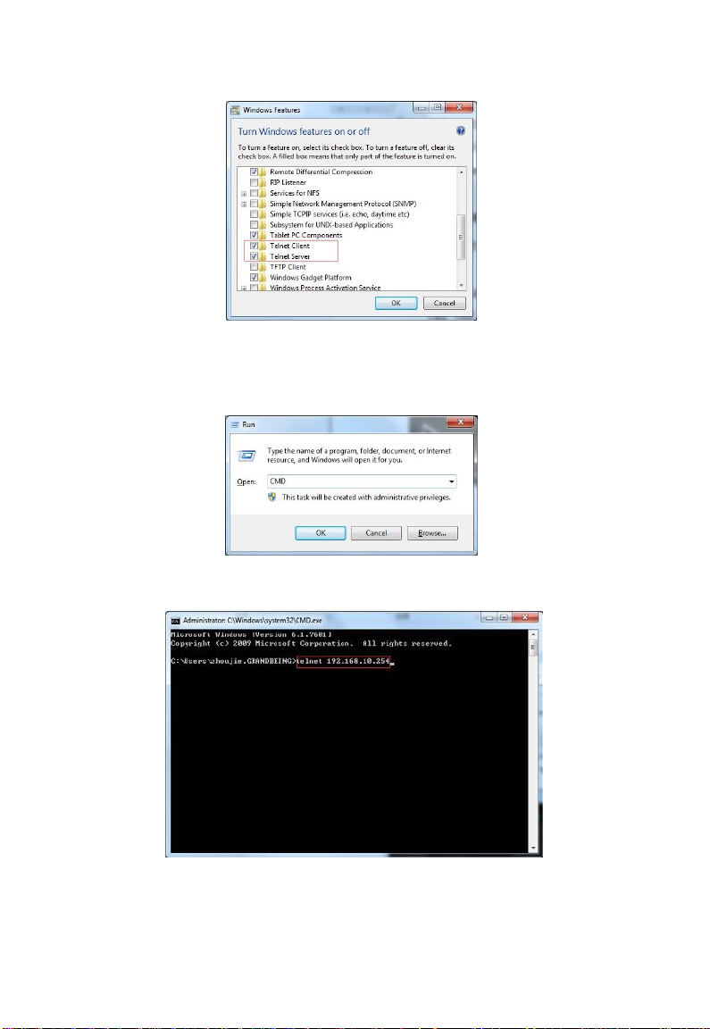
4. Connect between the control PC and matrix through telnet.
a) Launch the Run window on your computer, enter "CMD" in the
textbox, and then click "OK".
b) The following DOS window will pop up.
Input "telnet 192.168.10.254" and press Enter.
c) A new window will display and show "Welcome to use matrix telnet",
indicating telnet connection between the matrix and computer is
Page 21

established successfully. Now you could send API command to
control matrix through telnet. e.g.
Input: bc␣↵
It will response:
s13 s22
s33 s44
"␣" means to enter a space, "↵ " means to enter a carriage return
or a line feed.
This command is used to get the matrix mapping status from each
input to each output, and the result is that Output 1 corresponds to
Input 3, Output 2 corresponds to Input 2, Output 3 corresponds to
Input 3, Output 4 corresponds to Input 4.
For more commands please refer to separate document "API Command
Set_MX44-4KUHDE".
RS232 Serial Control
For RS232 serial control, professional serial interface software (e.g. UART
Assist) may be needed.
Before executing API commands through serial connection, ensure the RS232
port of the matrix and the control PC are configured correctly.
Page 22
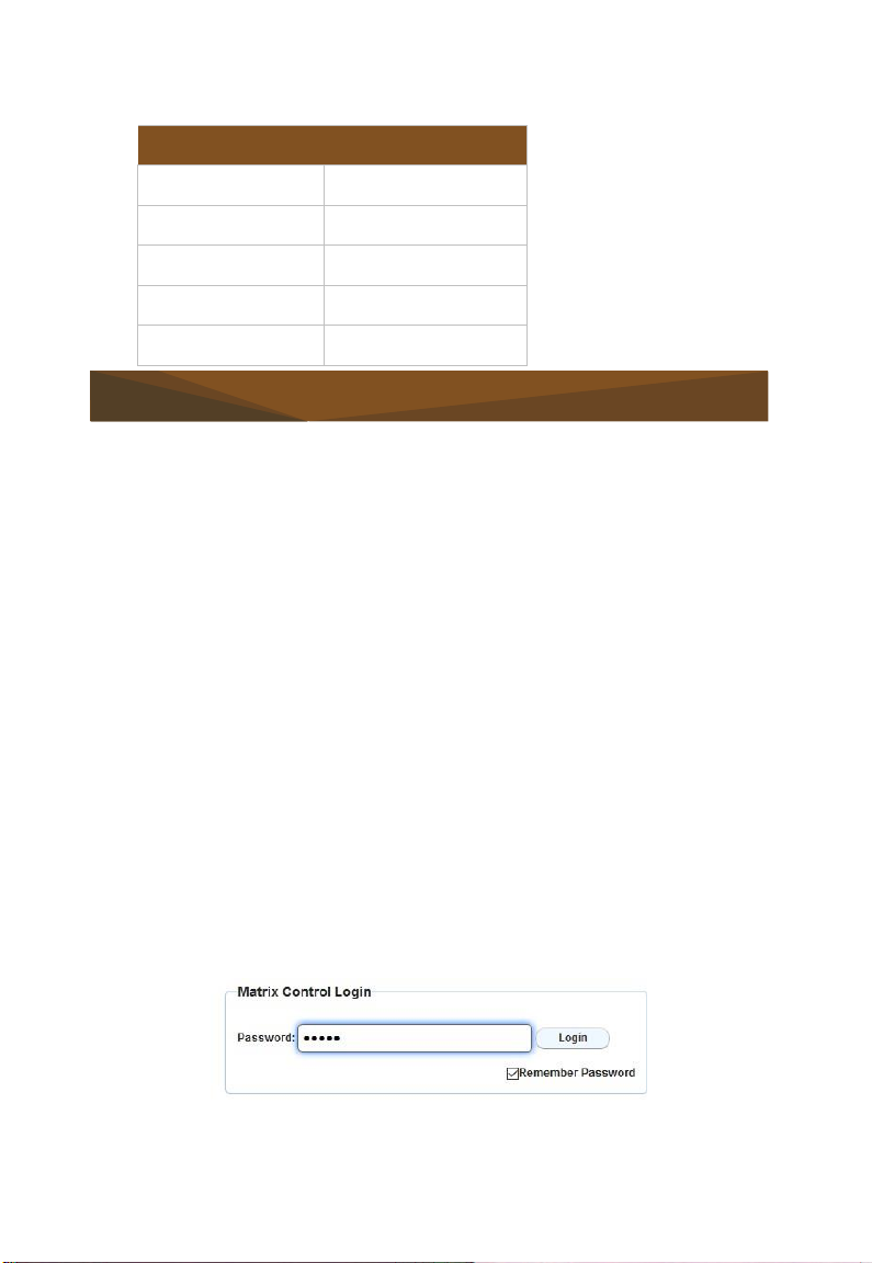
Value
Baud Rate
9600 bps
Data Bits
8 bits
Parity
None
Stop Bits
1 bit
Flow Control
None
Parameters
Web UI Control
The Web UI designed for the matrix is available for switching control, general
and advanced settings of the device. The Web UI is accessible through a
browser, e.g. Chrome, Firefox, Safari, Opera, IE10+, etc.
By default, the IP address for MX44-4KUHDE is 192.168.10.254, subnet mask
is 255.255.0.0.
Default login password for Web UI is "admin".
Access the Web Interface
1. Connect the LAN port of the matrix to your PC using a straight UTP cable.
2. Set your PC to the same network segment as the matrix, e.g.
192.168.X.X (X ranges 2~253)
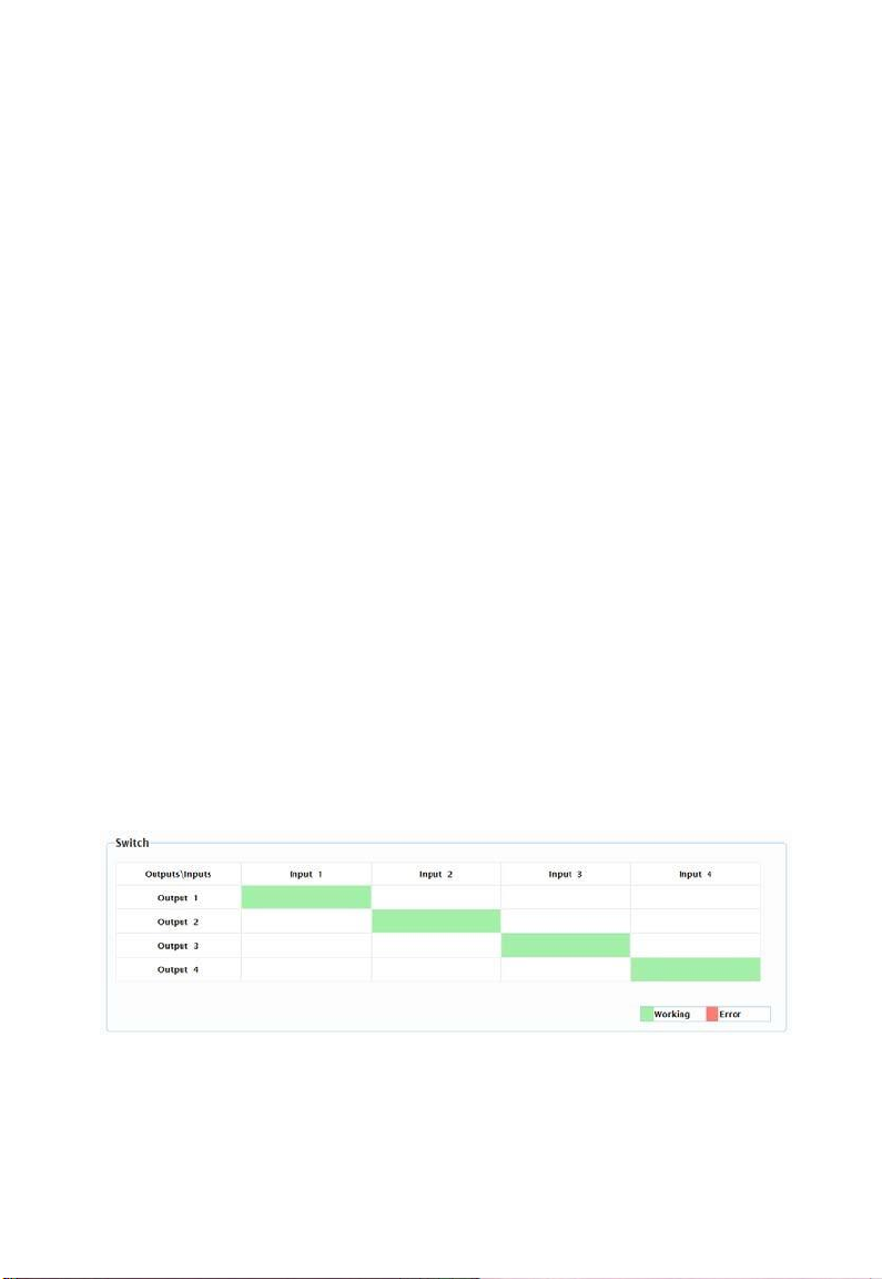
3. Input the IP address 192.168.10.254 in your browser and press Enter.
The following window will display. Enter the default password "admin"
and click Login to enter main screen of Web UI.
The main screen includes Matrix Control, General Setting and Advanced
Setting.
Page 23
The Matrix Control allows for input/output switching and Presets configuration.
The General Setting allows for setting login, EDID setting, factory default
setting and port naming.
The Advanced Setting allows for network and password setting, Web UI
update, logo customization.
Matrix Control
The Matrix Control page is used to perform the following functions:
Switch
Switch All
Presets
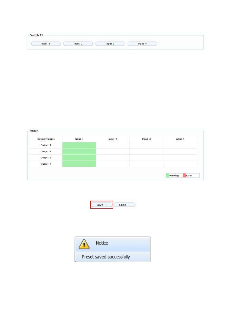
(1) Switch
The Switch section manages distribution of input sources to output displays.
By default, Input 1 corresponds to Output 1, Input 2 corresponds to Output 2,
Input (n) corresponds to Output (n), n = 1, 2, 3, 4.
Click the button in the table to select the input for the output display (button
turns from white to green once selection is done).
(2) Switch All
Input 1: Click to switch to Input (1) for Output 1-4.
Input (n): Click to switch to Input (n) for Output 1-4. (n = 1, 2, 3, 4)
Page 24
(3) Presets
The Presets section saves or loads the input/output switch settings to or from
the matrix.
Save: To save input/output settings in the Switch/Switch All section.
Load: To load input/output settings in the Switch/Switch All section.
To save an input/output setting to Preset 1:
1. Complete the input and output settings in the Switch section.
2. Click "Save 1" in "Preset 1".
3. The following window will display in the upper right corner to indicate
Preset 1 is saved successfully.
General Setting
General Setting is available to perform the following functions:
Matrix Setting Login
Page 25
EDID Setting
Port Naming
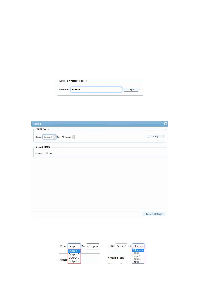
(1) Matrix Setting Login
1. Enter the default password "123456" for Matrix Setting Login in the
password box below and Click "Login".
2. The Setting window will display as follows, including EDID Copy, Smart
EDID Section and Factory Default button.
EDID Copy: Click the drop-down menu to copy EDID from the Output (1-4) to
Input(s) chosen.
Page 26
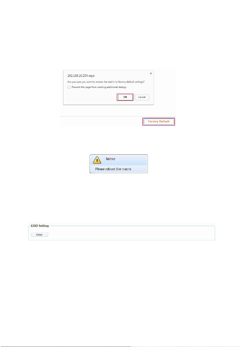
Smart EDID: Click ON or OFF to enable or disable the Smart EDID setting.
Factory Default: Click to restore the matrix to default settings, and then click
"OK".
The Notice window will pop up, please reboot the matrix and wait for at least
2 minutes to re-login Web UI.
Note: To enable EDID COPY and Smart EDID function above, you must set
the EDID DIP switch on rear panel to "000" position firstly.
(2) EDID Setting
Click Enter to open the EDID Setting page.
Page 27
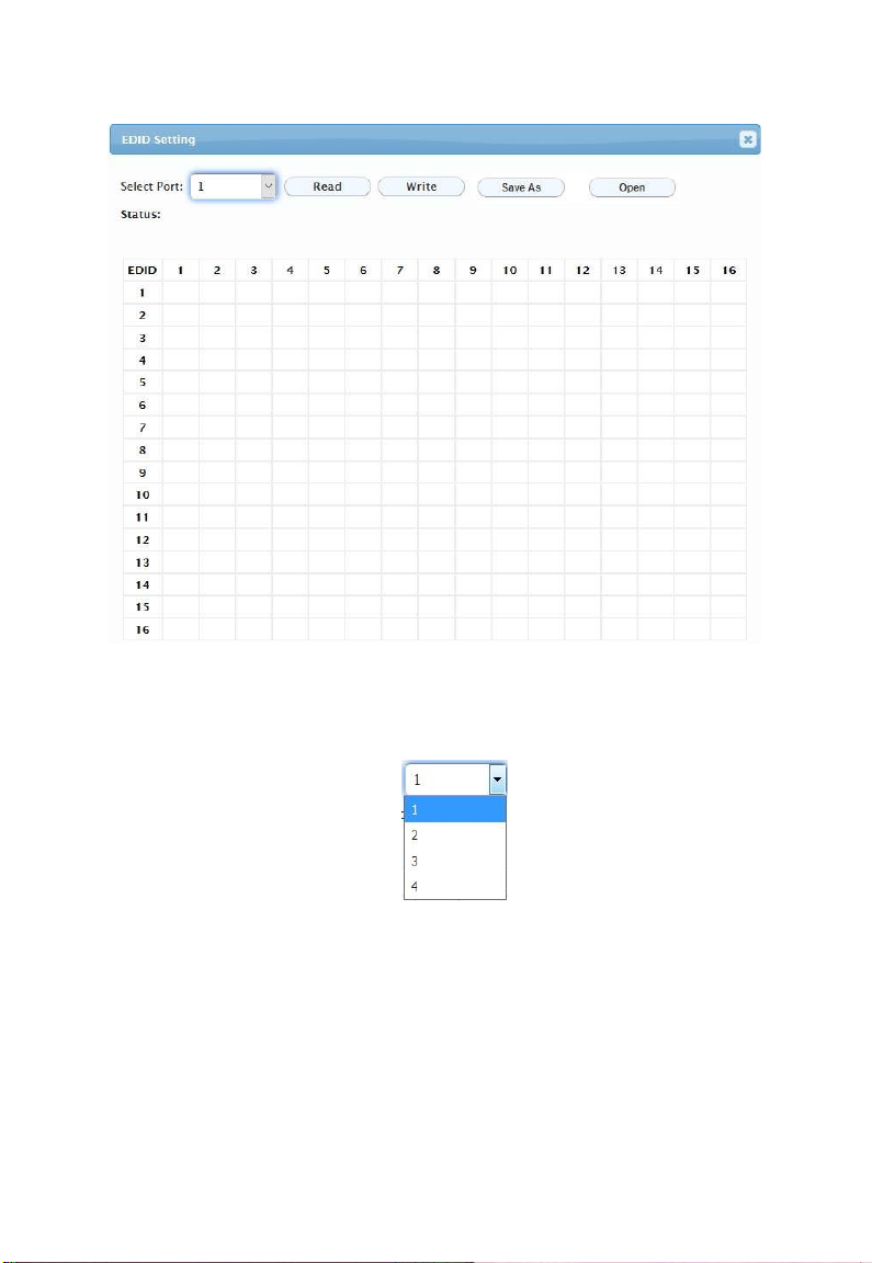
Select Port: Click the drop-down menu to choose an Output port (1-4) for
EDID setting.
Read: Click to read the EDID of the Output port you choose. The following
EDID table will appear.
Page 28
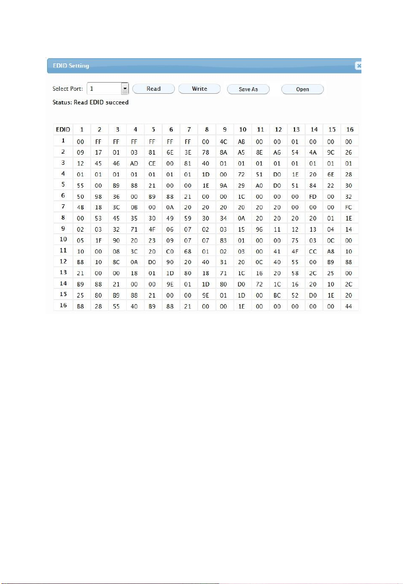
Write: Click to write the EDID of the Output port you choose to corresponding
Input.
Page 29
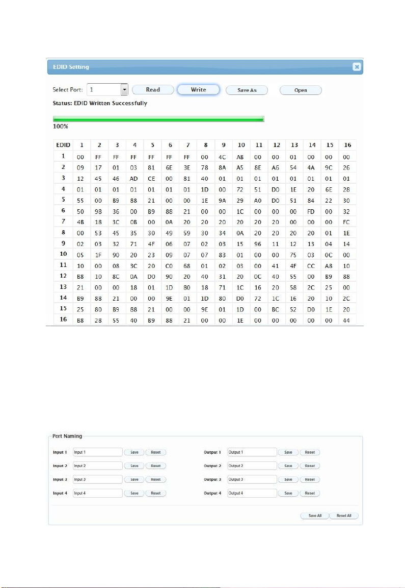
Save as: Click to save the EDID of the Output as bin file to a desired location.
Open: Click to open an EDID file. Then you can click "Write" to write the EDID
information instead of Output port's EDID to corresponding Input.
(3) Port Naming
Port Naming allows you to set easy to remember names for inputs and outputs.
Save: click to save and apply changes.
Page 30
Reset: click to reset changes.
Save All: click to save and apply all changes.
Reset All: click to reset all changes.
Advanced Setting
Advanced Setting is available to perform the following functions:
Network
Change Password
Matrix Setting Password
Update Web UI
Log
Customize Web UI logo
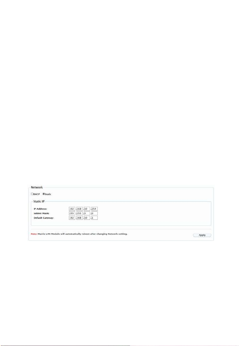
(1) Network
Network is used to set the dynamic/static IP address.
DHCP: once enabled, IP address of the matrix is assigned automatically
by the DHCP server connected.
Static: When the matrix fails to obtain or detect an IP address from the
network connected, select "Static" to set up the IP address manually.
The default address of the matrix is 192.168.10.254.
Apply: click to enable the network settings.
Note:
Page 31
1) When "Static" is selected, ensure your PC is in the same network
segment as the matrix, i.e. the IP address of your PC should be set as
192.168.x.x. (x is suggested to between 2 to 253)
2) Please wait for 2 to 3 minutes for the matrix LAN module to reboot and
reconnect after the network settings are changed.
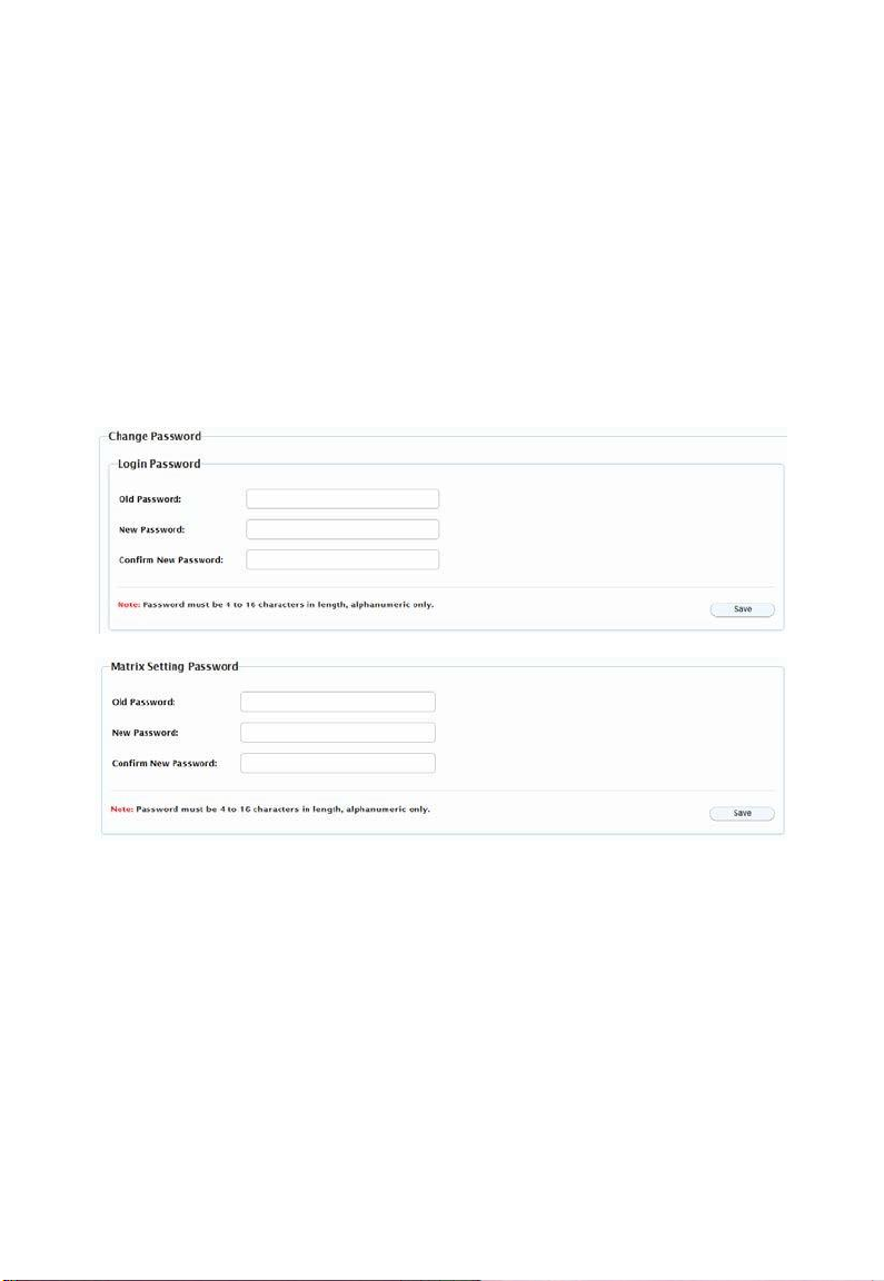
(2) Change Login/Matrix Setting Password
Default Login password is "admin”; default Matrix Setting password is
“123456”.
Save: click to save changes.
Note: The new password must contain 4 to 16 characters (alphanumeric only).
(3) Update Web UI
1. Click “Browse” for the update file.
2. Click "Update" to start the Web UI upgrade.
3. The matrix LAN Module will update and reboot automatically when Web
UI is completed. Please wait for about 3 minutes and then refresh and
log in again.
Page 32
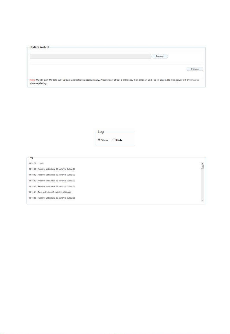
Note: DO NOT disconnect the matrix during update process.
(4) Log
Show: Click to show the Log window at the bottom of the Matrix Control and
General Setting Pages.
Hide: Click to hide the Log window at the bottom of the Matrix Control and
General Setting Pages.
(5) Custom Web UI LOGO
Custom Web UI Logo allows you to create your own logo for the Web UI you
are using.
1. Click "Browse" to upload the new logo file. An image file in PNG format
with a resolution of 234x80 pixels is suggested.
Page 33
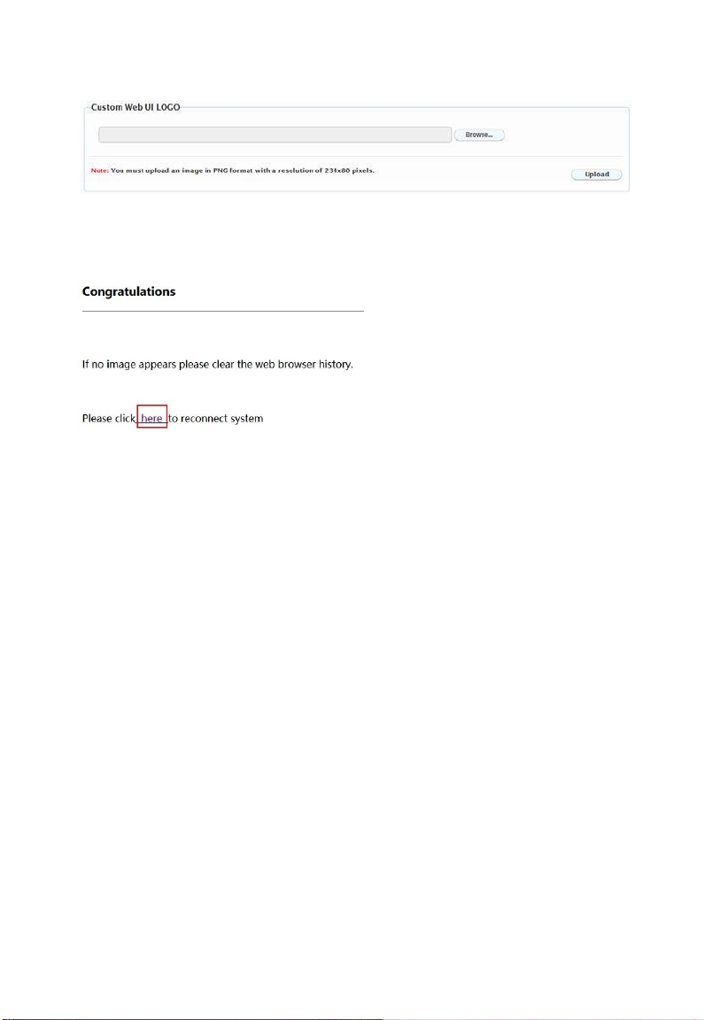
2. Click "Upload", the following window will appear. Click "here" to
reconnect the system.
3. The new logo will appear on the upper left corner of the screen.
Page 34

Warranty Terms and Conditions
For the following cases LINK Brand shall charge for the service(s) claimed for
the products if the product is still remediable and the warranty card becomes
unenforceable or inapplicable.
1. The original serial number (specified by LINK Brand) labeled on the
product has been removed, erased, replaced, defaced or is illegible.
2. The warranty has expired.
3. The defects are caused by the fact that the product is repaired,
dismantled or altered by anyone that is not from a LINK Brand authorized
service partner. The defects are caused by the fact that the product is
used or handled improperly, roughly or not as instructed in the applicable
User Guide.
4. The defects are caused by any superior force including but not limited to
accidents, fire, earthquake, lightning, tsunami and war.
5. The service, configuration and gifts promised by salesman only but not
covered by normal contract.
6. LINK Brand preserves the right for interpretation of these cases above
and to make changes to them at any time without notice.
Page 35
WWW.MSTRBRAND.COM
 Loading...